EP4458552A1 - A hybrid manufacturing method comprising an additive manufacturing step and a product resulting from such a method - Google Patents
A hybrid manufacturing method comprising an additive manufacturing step and a product resulting from such a method Download PDFInfo
- Publication number
- EP4458552A1 EP4458552A1 EP23171941.0A EP23171941A EP4458552A1 EP 4458552 A1 EP4458552 A1 EP 4458552A1 EP 23171941 A EP23171941 A EP 23171941A EP 4458552 A1 EP4458552 A1 EP 4458552A1
- Authority
- EP
- European Patent Office
- Prior art keywords
- hmm
- coating
- manufacturing
- hybrid manufacturing
- surface treatment
- Prior art date
- Legal status (The legal status is an assumption and is not a legal conclusion. Google has not performed a legal analysis and makes no representation as to the accuracy of the status listed.)
- Pending
Links
Images

Classifications
-
- B—PERFORMING OPERATIONS; TRANSPORTING
- B29—WORKING OF PLASTICS; WORKING OF SUBSTANCES IN A PLASTIC STATE IN GENERAL
- B29C—SHAPING OR JOINING OF PLASTICS; SHAPING OF MATERIAL IN A PLASTIC STATE, NOT OTHERWISE PROVIDED FOR; AFTER-TREATMENT OF THE SHAPED PRODUCTS, e.g. REPAIRING
- B29C64/00—Additive manufacturing, i.e. manufacturing of three-dimensional [3D] objects by additive deposition, additive agglomeration or additive layering, e.g. by 3D printing, stereolithography or selective laser sintering
- B29C64/10—Processes of additive manufacturing
- B29C64/188—Processes of additive manufacturing involving additional operations performed on the added layers, e.g. smoothing, grinding or thickness control
-
- B—PERFORMING OPERATIONS; TRANSPORTING
- B29—WORKING OF PLASTICS; WORKING OF SUBSTANCES IN A PLASTIC STATE IN GENERAL
- B29C—SHAPING OR JOINING OF PLASTICS; SHAPING OF MATERIAL IN A PLASTIC STATE, NOT OTHERWISE PROVIDED FOR; AFTER-TREATMENT OF THE SHAPED PRODUCTS, e.g. REPAIRING
- B29C64/00—Additive manufacturing, i.e. manufacturing of three-dimensional [3D] objects by additive deposition, additive agglomeration or additive layering, e.g. by 3D printing, stereolithography or selective laser sintering
- B29C64/10—Processes of additive manufacturing
- B29C64/106—Processes of additive manufacturing using only liquids or viscous materials, e.g. depositing a continuous bead of viscous material
- B29C64/118—Processes of additive manufacturing using only liquids or viscous materials, e.g. depositing a continuous bead of viscous material using filamentary material being melted, e.g. fused deposition modelling [FDM]
-
- B—PERFORMING OPERATIONS; TRANSPORTING
- B24—GRINDING; POLISHING
- B24B—MACHINES, DEVICES, OR PROCESSES FOR GRINDING OR POLISHING; DRESSING OR CONDITIONING OF ABRADING SURFACES; FEEDING OF GRINDING, POLISHING, OR LAPPING AGENTS
- B24B1/00—Processes of grinding or polishing; Use of auxiliary equipment in connection with such processes
-
- B—PERFORMING OPERATIONS; TRANSPORTING
- B29—WORKING OF PLASTICS; WORKING OF SUBSTANCES IN A PLASTIC STATE IN GENERAL
- B29C—SHAPING OR JOINING OF PLASTICS; SHAPING OF MATERIAL IN A PLASTIC STATE, NOT OTHERWISE PROVIDED FOR; AFTER-TREATMENT OF THE SHAPED PRODUCTS, e.g. REPAIRING
- B29C64/00—Additive manufacturing, i.e. manufacturing of three-dimensional [3D] objects by additive deposition, additive agglomeration or additive layering, e.g. by 3D printing, stereolithography or selective laser sintering
- B29C64/30—Auxiliary operations or equipment
-
- B—PERFORMING OPERATIONS; TRANSPORTING
- B29—WORKING OF PLASTICS; WORKING OF SUBSTANCES IN A PLASTIC STATE IN GENERAL
- B29C—SHAPING OR JOINING OF PLASTICS; SHAPING OF MATERIAL IN A PLASTIC STATE, NOT OTHERWISE PROVIDED FOR; AFTER-TREATMENT OF THE SHAPED PRODUCTS, e.g. REPAIRING
- B29C71/00—After-treatment of articles without altering their shape; Apparatus therefor
-
- B—PERFORMING OPERATIONS; TRANSPORTING
- B29—WORKING OF PLASTICS; WORKING OF SUBSTANCES IN A PLASTIC STATE IN GENERAL
- B29C—SHAPING OR JOINING OF PLASTICS; SHAPING OF MATERIAL IN A PLASTIC STATE, NOT OTHERWISE PROVIDED FOR; AFTER-TREATMENT OF THE SHAPED PRODUCTS, e.g. REPAIRING
- B29C71/00—After-treatment of articles without altering their shape; Apparatus therefor
- B29C71/02—Thermal after-treatment
-
- B—PERFORMING OPERATIONS; TRANSPORTING
- B33—ADDITIVE MANUFACTURING TECHNOLOGY
- B33Y—ADDITIVE MANUFACTURING, i.e. MANUFACTURING OF THREE-DIMENSIONAL [3D] OBJECTS BY ADDITIVE DEPOSITION, ADDITIVE AGGLOMERATION OR ADDITIVE LAYERING, e.g. BY 3D PRINTING, STEREOLITHOGRAPHY OR SELECTIVE LASER SINTERING
- B33Y10/00—Processes of additive manufacturing
-
- B—PERFORMING OPERATIONS; TRANSPORTING
- B33—ADDITIVE MANUFACTURING TECHNOLOGY
- B33Y—ADDITIVE MANUFACTURING, i.e. MANUFACTURING OF THREE-DIMENSIONAL [3D] OBJECTS BY ADDITIVE DEPOSITION, ADDITIVE AGGLOMERATION OR ADDITIVE LAYERING, e.g. BY 3D PRINTING, STEREOLITHOGRAPHY OR SELECTIVE LASER SINTERING
- B33Y40/00—Auxiliary operations or equipment, e.g. for material handling
- B33Y40/10—Pre-treatment
-
- B—PERFORMING OPERATIONS; TRANSPORTING
- B33—ADDITIVE MANUFACTURING TECHNOLOGY
- B33Y—ADDITIVE MANUFACTURING, i.e. MANUFACTURING OF THREE-DIMENSIONAL [3D] OBJECTS BY ADDITIVE DEPOSITION, ADDITIVE AGGLOMERATION OR ADDITIVE LAYERING, e.g. BY 3D PRINTING, STEREOLITHOGRAPHY OR SELECTIVE LASER SINTERING
- B33Y40/00—Auxiliary operations or equipment, e.g. for material handling
- B33Y40/20—Post-treatment, e.g. curing, coating or polishing
-
- B—PERFORMING OPERATIONS; TRANSPORTING
- B62—LAND VEHICLES FOR TRAVELLING OTHERWISE THAN ON RAILS
- B62D—MOTOR VEHICLES; TRAILERS
- B62D27/00—Connections between superstructure or understructure sub-units
- B62D27/02—Connections between superstructure or understructure sub-units rigid
- B62D27/023—Assembly of structural joints
-
- B—PERFORMING OPERATIONS; TRANSPORTING
- B29—WORKING OF PLASTICS; WORKING OF SUBSTANCES IN A PLASTIC STATE IN GENERAL
- B29C—SHAPING OR JOINING OF PLASTICS; SHAPING OF MATERIAL IN A PLASTIC STATE, NOT OTHERWISE PROVIDED FOR; AFTER-TREATMENT OF THE SHAPED PRODUCTS, e.g. REPAIRING
- B29C59/00—Surface shaping of articles, e.g. embossing; Apparatus therefor
- B29C59/02—Surface shaping of articles, e.g. embossing; Apparatus therefor by mechanical means, e.g. pressing
- B29C2059/027—Grinding; Polishing
-
- B—PERFORMING OPERATIONS; TRANSPORTING
- B29—WORKING OF PLASTICS; WORKING OF SUBSTANCES IN A PLASTIC STATE IN GENERAL
- B29C—SHAPING OR JOINING OF PLASTICS; SHAPING OF MATERIAL IN A PLASTIC STATE, NOT OTHERWISE PROVIDED FOR; AFTER-TREATMENT OF THE SHAPED PRODUCTS, e.g. REPAIRING
- B29C71/00—After-treatment of articles without altering their shape; Apparatus therefor
- B29C71/02—Thermal after-treatment
- B29C2071/022—Annealing
-
- B—PERFORMING OPERATIONS; TRANSPORTING
- B29—WORKING OF PLASTICS; WORKING OF SUBSTANCES IN A PLASTIC STATE IN GENERAL
- B29L—INDEXING SCHEME ASSOCIATED WITH SUBCLASS B29C, RELATING TO PARTICULAR ARTICLES
- B29L2031/00—Other particular articles
- B29L2031/30—Vehicles, e.g. ships or aircraft, or body parts thereof
Definitions
- the disclosure relates generally to a manufacturing method.
- the disclosure relates to a hybrid manufacturing method comprising an additive manufacturing step and a product resulting from such a method.
- the disclosure can be applied in heavy-duty vehicles, such as trucks, buses, and construction equipment.
- trucks, buses, and construction equipment such as trucks, buses, and construction equipment.
- a hybrid manufacturing method comprises: providing a base member, the base member comprising a metallic portion provided with a coating; providing a surface treatment to all or part of the coating, the surface treatment comprising a mechanical, a chemical and/or a physical treatment, to obtain a treated base surface; and forming an additional part onto the treated base surface by additive manufacturing.
- the surface treatment may result in a total or partial removal and/or a chemical and/or physical change of the coating itself.
- the surface treatment may be a surface alteration.
- the surface treatment may comprise sanding, grinding, blast cleaning or any mechanical surface treatment, stripping, etching, pickling or any chemical surface treatment, heating, firing, plasma or laser treatment or any physical surface treatment.
- fused deposition modeling may be used as additive manufacturing.
- a single or several additional parts may be formed.
- the first aspect of the disclosure may seek to provide quick, versatile and/or cost effective way of manufacturing.
- a technical benefit may include a strong fastening / adhesion strength between the base member and the additional part, for example due to the surface treatment step, with quick, versatile and cost effective way of manufacturing.
- the surface treatment may generate microstructure improving a mechanical anchorage of the additional part on the treated base surface.
- a chemical treatment may provide a microstructure when the plasma treatment may provide a nanostructure to the treated base surface.
- the surface treatment may comprise removing at least in part the coating.
- the surface treatment may comprise a predetermined pattern.
- the surface treatment may result in a pattern, for example with reliefs, formed at the treated surface.
- the predetermined pattern may have a shape of grid, hatch, staggered, line grids, pads, etc.
- the all or part of the coating may be have been removed in accordance with such a predetermined pattern. This may help to provide a regular and homogeneous interface between the base member and the additional part with a good balance between the extent of the surface treatment and the resulting fastening/adhesion strength.
- the coating may comprise resin and the surface treatment may comprise thermal or chemical treatment to provide adhesive features to at least a portion of the coating.
- the shear resistance of the base member material constitutes sort of a minimum threshold value below which it is considered that the interface is adhesive and above which the interface might not be adhesive (e.g. minimum shear force).
- minimum threshold value depends on the vibration environment (where the component will be installed and operated, e.g. unsprung mass such as axle, sprung mass such as chassis).
- the thermal or chemical treatment may locally transform/change/impact the resin to be used as an adhesion agent.
- the hybrid manufacturing method may comprise, before forming the additional part, providing a layer of adhesive material onto the treated base surface.
- the adhesive material may be a silane type coupling agent.
- the hybrid manufacturing method may comprise, after forming the additional part, a post-treatment such as annealing at high temperature. This may improve the adhesion between the additional part and the treated base surface, or between the the additional part, the optional adhesive material and the treated base surface.
- the high temperature may be 100°C or more.
- the additional part may be made of polymeric material, for example thermoplastic, thermoset or resin.
- the polymeric material may be a fiber reinforced polymer or thermoplastic. Such a material may help to provide quick, versatile and cost effective way of manufacturing while providing satisfactory strength/resistance to the additional part(s).
- the coating may comprise an optional e-coat (or electro deposition coating) primer and a top-coat layer.
- a top-coat layer may be a layer of paint or the like.
- the base member may be all or part of a vehicle chassis or of a vehicle body, and the additional part may a bracket, a fastener, a mounting part, an informative element such as a brand plate, logo, location marker, or the like.
- a device may be obtained by the hybrid manufacturing method according to any example of the present disclosure.
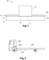
- FIG. 1 shows specific non limitative example of device obtained by such a hybrid manufacturing method HMM, such as a bracket 52A or an informative element 52B.
- the hybrid manufacturing method HHM comprises a step SA of providing a base member 10, the base member 10 comprising a metallic portion 12 provided with a coating 14.
- the coating 14 may comprise an optional e-coat primer 14A and a top-coat layer 14B.
- the hybrid manufacturing method HHM comprises a step SB of providing a surface treatment to all or part of the coating 14, the surface treatment comprising a mechanical, a chemical and/or a physical treatment, to obtain a treated base surface S.
- the surface treatment SB may comprise removing at least in part the coating 14.
- the surface treatment SB may comprise removing all or part of the top-coat layer 14B only.
- the surface SB may also comprise removing all or part of the e-coat primer 14A.
- the treated surface S may be formed by a surface wherein all the coating 14 has been continuously removed as shown in figure 4A .
- the surface treatment may comprise a predetermined pattern.
- the predetermined pattern may result from a removal of the coating 14 in accordance with a hatched pattern (see fig. 4B , treated base surface S'), a grid pattern (see fig. 4C , treated base surface S"), a staggered pattern (see fig. 4D , treated base surface S′′′), a pad pattern (see fig. 4E , treated base surface S" "), etc.
- the pattern for the top-coat 14B may be similar to or different from the pattern for the e-coat primer 14A.
- the coating 14 may comprise resin and the surface treatment SB may comprise thermal or chemical treatment to provide adhesive features to at least a portion of the coating 14.
- the hybrid manufacturing method HHM comprises a step SD of forming an additional part 20 onto the treated base surface S by additive manufacturing.
- the additive manufacturing SD may be a fused deposition modeling, also known as FDM.
- the additional part 20 may be made of polymeric material, for example thermoplastic, thermoset or resin.
- the polymeric material may be a fiber reinforced polymer or thermoplastic.
- the steps SA, SB and SD may be carried out in that order.
- the hybrid manufacturing method HHM may comprise an optional step SC, before the additive manufacturing step SD and after the surface treatment step SB, of providing a layer 16 of adhesive material onto the treated base surface S.
- the hybrid manufacturing method HHM may comprise an optional step SE, after the additive manufacturing step SD, a post-treatment such as annealing at high temperature, for example 100°C.
- the base member 12 may be all or part of a vehicle chassis 50A or of a vehicle body 50B.
- the additional part 20 may form a bracket 52A, or a not shown fastener, mounting part, etc., and may be formed either on the vehicle chassis 50A or on the vehicle body 50B.
- the addition part 20 may form an informative element 52B such as a brand plate, a logo, a location marker, etc. and may be formed either on the vehicle chassis 50A or on the vehicle body 50B.
- Relative terms such as “below” or “above” or “upper” or “lower” or “horizontal” or “vertical” may be used herein to describe a relationship of one element to another element as illustrated in the Figures. It will be understood that these terms and those discussed above are intended to encompass different orientations of the device in addition to the orientation depicted in the Figures. It will be understood that when an element is referred to as being “connected” or “coupled” to another element, it can be directly connected or coupled to the other element, or intervening elements may be present. In contrast, when an element is referred to as being “directly connected” or “directly coupled” to another element, there are no intervening elements present.
Landscapes
- Engineering & Computer Science (AREA)
- Chemical & Material Sciences (AREA)
- Materials Engineering (AREA)
- Manufacturing & Machinery (AREA)
- Mechanical Engineering (AREA)
- Physics & Mathematics (AREA)
- Optics & Photonics (AREA)
- Thermal Sciences (AREA)
- Combustion & Propulsion (AREA)
- Transportation (AREA)
- Application Of Or Painting With Fluid Materials (AREA)
Abstract
A hybrid manufacturing method, HMM, comprising :- providing a base member (10), the base member comprising a metallic portion (12) provided with a coating (14),- providing a surface treatment to all or part of the coating (14), the surface treatment comprising a mechanical, a chemical and/or a physical treatment, to obtain a treated base surface (S), and- forming an additional part (20) onto the treated base surface (S) by additive manufacturing.
Description
- The disclosure relates generally to a manufacturing method. In particular aspects, the disclosure relates to a hybrid manufacturing method comprising an additive manufacturing step and a product resulting from such a method. The disclosure can be applied in heavy-duty vehicles, such as trucks, buses, and construction equipment. Although the disclosure may be described with respect to a particular vehicle, the disclosure is not restricted to any particular vehicle.
- Traditional assembly of an additional component on a metallic structure may comprise fastening system such as metallic or plastic clips, screw joints, etc.. These solutions require at least one drilling, cutting, etc. step of the metallic structure, an appropriate supply chain and an installation process. This may increase the manufacturing time and costs. Therefore, a need exists to provide a metallic structure equipped with an additional component the manufacturing of which being quicker, versatile and/or cost effective.
- According to a first aspect of the disclosure, a hybrid manufacturing method comprises: providing a base member, the base member comprising a metallic portion provided with a coating; providing a surface treatment to all or part of the coating, the surface treatment comprising a mechanical, a chemical and/or a physical treatment, to obtain a treated base surface; and forming an additional part onto the treated base surface by additive manufacturing. The surface treatment may result in a total or partial removal and/or a chemical and/or physical change of the coating itself. In other words, the surface treatment may be a surface alteration. For example, the surface treatment may comprise sanding, grinding, blast cleaning or any mechanical surface treatment, stripping, etching, pickling or any chemical surface treatment, heating, firing, plasma or laser treatment or any physical surface treatment. For example, fused deposition modeling (or FDM) may be used as additive manufacturing. A single or several additional parts may be formed. The first aspect of the disclosure may seek to provide quick, versatile and/or cost effective way of manufacturing. A technical benefit may include a strong fastening / adhesion strength between the base member and the additional part, for example due to the surface treatment step, with quick, versatile and cost effective way of manufacturing. For example, the surface treatment may generate microstructure improving a mechanical anchorage of the additional part on the treated base surface. A chemical treatment may provide a microstructure when the plasma treatment may provide a nanostructure to the treated base surface.
- In some examples, the surface treatment may comprise removing at least in part the coating.
- In some examples, the surface treatment may comprise a predetermined pattern. The surface treatment may result in a pattern, for example with reliefs, formed at the treated surface. For example, the predetermined pattern may have a shape of grid, hatch, staggered, line grids, pads, etc. For example, the all or part of the coating may be have been removed in accordance with such a predetermined pattern. This may help to provide a regular and homogeneous interface between the base member and the additional part with a good balance between the extent of the surface treatment and the resulting fastening/adhesion strength.
- In some examples, the coating may comprise resin and the surface treatment may comprise thermal or chemical treatment to provide adhesive features to at least a portion of the coating. By 'adhesive features', it is meant that it confers a shear resistance that is superior or equal to the shear resistance of the base member material itself, in such a way that the coating does not constitute the weakest point along shear direction. As a result, the shear resistance of the base member material constitutes sort of a minimum threshold value below which it is considered that the interface is adhesive and above which the interface might not be adhesive (e.g. minimum shear force). However, such minimum threshold value depends on the vibration environment (where the component will be installed and operated, e.g. unsprung mass such as axle, sprung mass such as chassis). Such adhesive features may help to improve fastening/adhesion strength between the base member and the additional part, withstanding external loads and vibrations in use. For example, the thermal or chemical treatment may locally transform/change/impact the resin to be used as an adhesion agent.
- In some examples, the hybrid manufacturing method may comprise, before forming the additional part, providing a layer of adhesive material onto the treated base surface. For example, the adhesive material may be a silane type coupling agent.
- In some examples, the hybrid manufacturing method may comprise, after forming the additional part, a post-treatment such as annealing at high temperature. This may improve the adhesion between the additional part and the treated base surface, or between the the additional part, the optional adhesive material and the treated base surface. The high temperature may be 100°C or more.
- In some examples, the additional part may be made of polymeric material, for example thermoplastic, thermoset or resin. For example, the polymeric material may be a fiber reinforced polymer or thermoplastic. Such a material may help to provide quick, versatile and cost effective way of manufacturing while providing satisfactory strength/resistance to the additional part(s).
- In some examples, the coating may comprise an optional e-coat (or electro deposition coating) primer and a top-coat layer. A top-coat layer may be a layer of paint or the like.
- In some examples, the base member may be all or part of a vehicle chassis or of a vehicle body, and the additional part may a bracket, a fastener, a mounting part, an informative element such as a brand plate, logo, location marker, or the like.
- According to a second aspect of the disclosure, a device may be obtained by the hybrid manufacturing method according to any example of the present disclosure.
- The above aspects, accompanying claims, and/or examples disclosed herein above and later below may be suitably combined with each other as would be apparent to anyone of ordinary skill in the art.
- Additional features and advantages are disclosed in the following description, claims, and drawings, and in part will be readily apparent therefrom to those skilled in the art or recognized by practicing the disclosure as described herein. There are also disclosed herein control units, computer readable media, and computer program products associated with the above discussed technical benefits.
- With reference to the appended drawings, below follows a more detailed description of aspects of the disclosure cited as examples.
-
FIG. 1 is an exemplary device obtained by a hybrid manufacturing method according to one example, -
FIG. 2 is an exemplary vehicle, serving as an example of base member according to one example, -
FIG. 3 is a flow chart of an exemplary hybrid manufacturing method according to one example, and -
FIG. 4A to 4E show examples of treated base surfaces. - Aspects set forth below represent the necessary information to enable those skilled in the art to practice the disclosure.
- A hybrid manufacturing method HMM and a
device 100 obtained by such a hybrid manufacturing method HMM are described with reference tofigures 1 to 4E .Figure 2 shows specific non limitative example of device obtained by such a hybrid manufacturing method HMM, such as abracket 52A or aninformative element 52B. - The hybrid manufacturing method HHM comprises a step SA of providing a
base member 10, thebase member 10 comprising ametallic portion 12 provided with acoating 14. In the present example, thecoating 14 may comprise anoptional e-coat primer 14A and a top-coat layer 14B. - The hybrid manufacturing method HHM comprises a step SB of providing a surface treatment to all or part of the
coating 14, the surface treatment comprising a mechanical, a chemical and/or a physical treatment, to obtain a treated base surface S. For example, the surface treatment SB may comprise removing at least in part thecoating 14. For example, the surface treatment SB may comprise removing all or part of the top-coat layer 14B only. In a variant, the surface SB may also comprise removing all or part of thee-coat primer 14A. For example, the treated surface S may be formed by a surface wherein all thecoating 14 has been continuously removed as shown infigure 4A . In another example, the surface treatment may comprise a predetermined pattern. For example, the predetermined pattern may result from a removal of thecoating 14 in accordance with a hatched pattern (seefig. 4B , treated base surface S'), a grid pattern (seefig. 4C , treated base surface S"), a staggered pattern (seefig. 4D , treated base surface S‴), a pad pattern (seefig. 4E , treated base surface S" "), etc. The pattern for the top-coat 14B may be similar to or different from the pattern for thee-coat primer 14A. For example, thecoating 14 may comprise resin and the surface treatment SB may comprise thermal or chemical treatment to provide adhesive features to at least a portion of thecoating 14. - The hybrid manufacturing method HHM comprises a step SD of forming an
additional part 20 onto the treated base surface S by additive manufacturing. For example, the additive manufacturing SD may be a fused deposition modeling, also known as FDM. Theadditional part 20 may be made of polymeric material, for example thermoplastic, thermoset or resin. For example, the polymeric material may be a fiber reinforced polymer or thermoplastic. - The steps SA, SB and SD may be carried out in that order.
- In the present example, the hybrid manufacturing method HHM may comprise an optional step SC, before the additive manufacturing step SD and after the surface treatment step SB, of providing a
layer 16 of adhesive material onto the treated base surface S. In the present example, the hybrid manufacturing method HHM may comprise an optional step SE, after the additive manufacturing step SD, a post-treatment such as annealing at high temperature, for example 100°C. - As shown in
figure 2 , thebase member 12 may be all or part of avehicle chassis 50A or of avehicle body 50B. For example, theadditional part 20 may form abracket 52A, or a not shown fastener, mounting part, etc., and may be formed either on thevehicle chassis 50A or on thevehicle body 50B. According to another example, theaddition part 20 may form aninformative element 52B such as a brand plate, a logo, a location marker, etc. and may be formed either on thevehicle chassis 50A or on thevehicle body 50B. - The terminology used herein is for the purpose of describing particular aspects only and is not intended to be limiting of the disclosure. As used herein, the singular forms "a," "an," and "the" are intended to include the plural forms as well, unless the context clearly indicates otherwise. As used herein, the term "and/or" includes any and all combinations of one or more of the associated listed items. It will be further understood that the terms "comprises," "comprising," "includes," and/or "including" when used herein specify the presence of stated features, integers, steps, operations, elements, and/or components, but do not preclude the presence or addition of one or more other features, integers, steps, operations, elements, components, and/or groups thereof.
- It will be understood that, although the terms first, second, etc., may be used herein to describe various elements, these elements should not be limited by these terms. These terms are only used to distinguish one element from another. For example, a first element could be termed a second element, and, similarly, a second element could be termed a first element without departing from the scope of the present disclosure.
- Relative terms such as "below" or "above" or "upper" or "lower" or "horizontal" or "vertical" may be used herein to describe a relationship of one element to another element as illustrated in the Figures. It will be understood that these terms and those discussed above are intended to encompass different orientations of the device in addition to the orientation depicted in the Figures. It will be understood that when an element is referred to as being "connected" or "coupled" to another element, it can be directly connected or coupled to the other element, or intervening elements may be present. In contrast, when an element is referred to as being "directly connected" or "directly coupled" to another element, there are no intervening elements present.
- Unless otherwise defined, all terms (including technical and scientific terms) used herein have the same meaning as commonly understood by one of ordinary skill in the art to which this disclosure belongs. It will be further understood that terms used herein should be interpreted as having a meaning consistent with their meaning in the context of this specification and the relevant art and will not be interpreted in an idealized or overly formal sense unless expressly so defined herein.
- It is to be understood that the present disclosure is not limited to the aspects described above and illustrated in the drawings; rather, the skilled person will recognize that many changes and modifications may be made within the scope of the present disclosure and appended claims. In the drawings and specification, there have been disclosed aspects for purposes of illustration only and not for purposes of limitation, the scope of the inventive concepts being set forth in the following claims.
Claims (10)
- A hybrid manufacturing method (HMM) comprising :- providing (SA) a base member (10), the base member comprising a metallic portion (12) provided with a coating (14),- providing a surface treatment (SB) to all or part of the coating (14), the surface treatment comprising a mechanical, a chemical and/or a physical treatment, to obtain a treated base surface (S), and- forming (SD) an additional part (20) onto the treated base surface (S) by additive manufacturing.
- The hybrid manufacturing method (HMM) according to claim 1, wherein the surface treatment (SB) comprises removing at least in part the coating (14).
- The hybrid manufacturing method (HMM) according to claim 1 or 2, wherein the surface treatment (SB) comprises a predetermined pattern.
- The hybrid manufacturing method (HMM) according to any one of claims 1 to 3, wherein the coating (14) comprises resin and the surface treatment (SB) comprises thermal or chemical treatment to provide adhesive features to at least a portion of the coating (14).
- The hybrid manufacturing method (HMM) according to any one of claims 1 to 4, comprising, before forming (SD) the additional part (20), providing (SC) a layer (16) of adhesive material onto the treated base surface (S).
- The hybrid manufacturing method (HMM) according to any one of claims 1 to 5, comprising, after forming (SD) the additional part (20), a post-treatment (SE) such as annealing at high temperature.
- The hybrid manufacturing method (HMM) according to any one of claims 1 to 6, wherein the additional part (20) is made of polymeric material, for example thermoplastic, thermoset or resin.
- The hybrid manufacturing method (HMM) according to any one of claims 1 to 7, wherein the coating (14) comprises an optional e-coat primer (14A) and a top-coat layer (14B).
- The hybrid manufacturing method (HMM) according to any one of claims 1 to 8, wherein the base member is all or part of a vehicle chassis (50A) or of a vehicle body (50B), and the additional part is a bracket (52A), a fastener, a mounting part, an informative element (52B) such as a brand plate, logo, location marker, or the like.
- A device (100) obtained by the hybrid manufacturing method (HMM) according to any one of claims 1 to 9.
Priority Applications (3)
| Application Number | Priority Date | Filing Date | Title |
|---|---|---|---|
| EP23171941.0A EP4458552A1 (en) | 2023-05-05 | 2023-05-05 | A hybrid manufacturing method comprising an additive manufacturing step and a product resulting from such a method |
| US18/648,618 US20240367374A1 (en) | 2023-05-05 | 2024-04-29 | Hybrid manufacturing method comprising an additive manufacturing step and a product resulting from such a method |
| CN202410541060.8A CN118893821A (en) | 2023-05-05 | 2024-04-30 | Hybrid manufacturing method including an additive manufacturing step and products obtained by this method |
Applications Claiming Priority (1)
| Application Number | Priority Date | Filing Date | Title |
|---|---|---|---|
| EP23171941.0A EP4458552A1 (en) | 2023-05-05 | 2023-05-05 | A hybrid manufacturing method comprising an additive manufacturing step and a product resulting from such a method |
Publications (1)
| Publication Number | Publication Date |
|---|---|
| EP4458552A1 true EP4458552A1 (en) | 2024-11-06 |
Family
ID=86330136
Family Applications (1)
| Application Number | Title | Priority Date | Filing Date |
|---|---|---|---|
| EP23171941.0A Pending EP4458552A1 (en) | 2023-05-05 | 2023-05-05 | A hybrid manufacturing method comprising an additive manufacturing step and a product resulting from such a method |
Country Status (3)
| Country | Link |
|---|---|
| US (1) | US20240367374A1 (en) |
| EP (1) | EP4458552A1 (en) |
| CN (1) | CN118893821A (en) |
-
2023
- 2023-05-05 EP EP23171941.0A patent/EP4458552A1/en active Pending
-
2024
- 2024-04-29 US US18/648,618 patent/US20240367374A1/en active Pending
- 2024-04-30 CN CN202410541060.8A patent/CN118893821A/en active Pending
Non-Patent Citations (1)
| Title |
|---|
| ALHMOUDI AISHA ET AL: "Joining of polymer-metal hybrid structures by fused deposition modelling", 2022 ADVANCES IN SCIENCE AND ENGINEERING TECHNOLOGY INTERNATIONAL CONFERENCES (ASET), IEEE, 21 February 2022 (2022-02-21), pages 1 - 5, XP034103503, DOI: 10.1109/ASET53988.2022.9734841 * |
Also Published As
| Publication number | Publication date |
|---|---|
| CN118893821A (en) | 2024-11-05 |
| US20240367374A1 (en) | 2024-11-07 |
Similar Documents
| Publication | Publication Date | Title |
|---|---|---|
| EP2563561B1 (en) | Expandable insert with flexible substrate | |
| CN117585074A (en) | Reinforcement structure | |
| WO2002036338A1 (en) | Expansible synthetic resin baffle with magnetic attachment | |
| EP2176564A1 (en) | Dual coated cast iron brake rotor and method of construction | |
| US20210283999A1 (en) | Liftgate reinforcement arrangements | |
| US6984432B2 (en) | Damper and process thereof | |
| EP1401698B1 (en) | Automobile assembly | |
| KR20130031232A (en) | Improvements in or relating to foamed inserts | |
| US7186442B2 (en) | Constrained layer damper | |
| US20240367374A1 (en) | Hybrid manufacturing method comprising an additive manufacturing step and a product resulting from such a method | |
| US20180173830A1 (en) | Vehicle body composite coating and design method thereof | |
| US6292995B1 (en) | Powder coating as substrate for epoxy bonding of vibration isolation mounts | |
| CN112585374A (en) | Spiral spring device for suspension | |
| US20090000865A1 (en) | Soundproofing Coatings, Method for the Production Thereof and Use of the Same | |
| CN101545526A (en) | Low-noise gear | |
| FI3277860T3 (en) | Panel for vehicle comprising a coated steel sheet locally reinforced | |
| EP3842658B1 (en) | Suspension coil spring device | |
| CN113389872B (en) | Stamped wheels for cast plastics | |
| WO2017218644A1 (en) | Engine mount, system and method | |
| CN202338586U (en) | Novel brake pad | |
| JPS59143628A (en) | Reinforced covers made of synthetic resin such as under-cover in car and manufacture thereof | |
| CN109131147B (en) | Low stress attachment for high gloss weatherable polycarbonate trim applications | |
| CN224241100U (en) | Top beam structure reinforcing piece for improving low-frequency road noise of whole vehicle | |
| CN202863346U (en) | Composite bumper made of composite material including mixed fibers | |
| EP0702619A1 (en) | Fiber reinforced thermoplastic battery tray and manufacturing method therefor |
Legal Events
| Date | Code | Title | Description |
|---|---|---|---|
| PUAI | Public reference made under article 153(3) epc to a published international application that has entered the european phase |
Free format text: ORIGINAL CODE: 0009012 |
|
| STAA | Information on the status of an ep patent application or granted ep patent |
Free format text: STATUS: THE APPLICATION HAS BEEN PUBLISHED |
|
| AK | Designated contracting states |
Kind code of ref document: A1 Designated state(s): AL AT BE BG CH CY CZ DE DK EE ES FI FR GB GR HR HU IE IS IT LI LT LU LV MC ME MK MT NL NO PL PT RO RS SE SI SK SM TR |
|
| STAA | Information on the status of an ep patent application or granted ep patent |
Free format text: STATUS: REQUEST FOR EXAMINATION WAS MADE |
|
| 17P | Request for examination filed |
Effective date: 20241206 |