EP4458544A1 - A method and apparatus for manufacturing protective liners for structural profile parts of aircraft - Google Patents
A method and apparatus for manufacturing protective liners for structural profile parts of aircraft Download PDFInfo
- Publication number
- EP4458544A1 EP4458544A1 EP23171455.1A EP23171455A EP4458544A1 EP 4458544 A1 EP4458544 A1 EP 4458544A1 EP 23171455 A EP23171455 A EP 23171455A EP 4458544 A1 EP4458544 A1 EP 4458544A1
- Authority
- EP
- European Patent Office
- Prior art keywords
- sealant
- base
- mold
- base mold
- curing
- Prior art date
- Legal status (The legal status is an assumption and is not a legal conclusion. Google has not performed a legal analysis and makes no representation as to the accuracy of the status listed.)
- Granted
Links
Images

Classifications
-
- B—PERFORMING OPERATIONS; TRANSPORTING
- B29—WORKING OF PLASTICS; WORKING OF SUBSTANCES IN A PLASTIC STATE IN GENERAL
- B29C—SHAPING OR JOINING OF PLASTICS; SHAPING OF MATERIAL IN A PLASTIC STATE, NOT OTHERWISE PROVIDED FOR; AFTER-TREATMENT OF THE SHAPED PRODUCTS, e.g. REPAIRING
- B29C33/00—Moulds or cores; Details thereof or accessories therefor
- B29C33/30—Mounting, exchanging or centering
- B29C33/301—Modular mould systems [MMS], i.e. moulds built up by stacking mould elements, e.g. plates, blocks, rods
- B29C33/302—Assembling a large number of mould elements to constitute one cavity
-
- B—PERFORMING OPERATIONS; TRANSPORTING
- B29—WORKING OF PLASTICS; WORKING OF SUBSTANCES IN A PLASTIC STATE IN GENERAL
- B29C—SHAPING OR JOINING OF PLASTICS; SHAPING OF MATERIAL IN A PLASTIC STATE, NOT OTHERWISE PROVIDED FOR; AFTER-TREATMENT OF THE SHAPED PRODUCTS, e.g. REPAIRING
- B29C41/00—Shaping by coating a mould, core or other substrate, i.e. by depositing material and stripping-off the shaped article; Apparatus therefor
- B29C41/34—Component parts, details or accessories; Auxiliary operations
- B29C41/38—Moulds, cores or other substrates
-
- B—PERFORMING OPERATIONS; TRANSPORTING
- B29—WORKING OF PLASTICS; WORKING OF SUBSTANCES IN A PLASTIC STATE IN GENERAL
- B29L—INDEXING SCHEME ASSOCIATED WITH SUBCLASS B29C, RELATING TO PARTICULAR ARTICLES
- B29L2031/00—Other particular articles
- B29L2031/30—Vehicles, e.g. ships or aircraft, or body parts thereof
- B29L2031/3076—Aircrafts
- B29L2031/3082—Fuselages
Definitions
- the invention relates to a method and apparatus for manufacturing protective liners.
- EP 3 205 470 A1 discloses the manufacture of parts made of thermoplastic material, where injection means are used to inject the thermoplastic material, e.g., polyamide.
- EP 1 860 250 A2 discloses a seal for a facade system.
- EP 2 839 946 A2 discloses a transfer system and a method for applying a film material to an elongate member.
- EP 2 176 123 A1 discloses a composite laminate structure having an edge and an impact indicator which is carried by the edge.
- US 2017 / 0 152 949 A1 discloses a sealant containment assembly where at least a portion of a fastener pattern is bound between at least two components, such as components used to form a portion of an aircraft.
- the sealant containment assembly includes at least one sealant containment member that sealingly engages peripheral portions of the components.
- the sealant containment member forms a sealing chamber around at least a portion of the fastener pattern. Fluid sealant flows into the sealing chamber and cures to seal fasteners within the fastener pattern that connect the components together.
- GB 2 588 967 A discloses an aircraft structure, e.g. a stringer, rib, spar or rib attachment, that has a composite laminate body.
- the body has an edge and an edge cap covering the edge, wherein cured resin forming part of the body bonds the edge cap on the edge.
- the aircraft structure is manufactured by providing a dry fibre preform of a structural component, covering an edge of the preform with an edge cap, feeding or injecting uncured resin between the edge cap device and the edge of the preform to infuse the dry fibre preform and curing the resin.
- DE 10 2014 017 411 A1 discloses a method for manufacturing a fiber composite part.
- a thermoplastic or elastomeric edge protection is attached to an edge of the fiber composite before the matrix of the fiber composite component is cured. After attaching the edge protection, the matrix of the fiber composite component is cured.
- a tank wall liner can be manufactured in-situ by casting the sealant into a prepared mold that is formed at least at the bottom side by the part to be protected by the tank wall liner.
- the bottom portion forms the bottom side of the mold, whereas the ribs and stringers form a circumferential wall of the mold that prevents flowing of the potting sealant compound into neighboring molds.
- the invention provides a method for manufacturing protective liners for structural profile parts of a fuselage of an aircraft, the method comprising:
- the base molds are negative base molds.
- each negative base mold includes a molding groove as the molding feature.
- a complementary mold member that cooperatively forms a molding cavity with the base mold is applied to the uncured wet sealant in order to generate a profile that matches the portion to be protected.
- the complementary mold member is a positive mold member.
- step c) the uncured wet sealant is applied by moving a sealant applicator and the base molds relative to each other and injecting the uncured sealant into the continuous molding feature.
- the sealant applicator includes a nozzle member that is profiled so as to act as the complementary mold member and the matching profile is generated by moving the nozzle member and the base molds relative to each other while simultaneously applying the uncured wet sealant.
- the sealant applicator is stationary and the base molds are moving.
- step d) the curing is accelerated by curing the uncured wet sealant in a curing oven or autoclave.
- step d) at least one base mold is separated from its neighboring base mold in order to limit the length of the cured sealant member, preferably before inserting the separated base mold into the curing oven or autoclave.
- the method is performed in a continuous manner by performing the steps b) to e) in a cycle, whereby the respective base mold emptied in step e) is arranged to form the continuous molding feature in step b).
- the invention provides a method for manufacturing a protected structural profile part of a fuselage of an aircraft by performing the previously described method in order to obtain at least one cured sealant member and by attaching the cured sealant member to a structural profile part so as to form a protective liner and generate the protected structural profile part.
- the cured sealant member is attached by applying uncured wet sealant and letting it cure.
- the invention provides a manufacturing apparatus configured for performing a previously described method according to any of the preceding claims, the apparatus comprising:
- the sealant application mechanism comprises a complementary mold member that configured to be applied to the uncured wet sealant in order to generate a profile that matches the portion to be protected.
- the sealant application mechanism comprises a sealant applicator that is configured for injecting the uncured sealant into the continuous molding feature, wherein the sealant applicator and the base molds are movable relative to each other.
- the sealant applicator includes a nozzle member that is profiled so as to act as the complementary mold member and configured for generating the matching profile by moving the nozzle member and the base molds relative to each other while simultaneously applying the uncured wet sealant.
- the sealant applicator is stationary and the base molds are movable.
- the apparatus further comprises a curing oven or autoclave configured for curing the uncured wet sealant.
- the apparatus further comprises an automatic or manual transport device that is configured for transporting the base molds between different stations of the apparatus.
- the apparatus further comprises a second sealant applicator that is configured for applying uncured wet sealant so as to attach the cured sealant member to the structural profile part as a protective liner.
- a second sealant applicator that is configured for applying uncured wet sealant so as to attach the cured sealant member to the structural profile part as a protective liner.
- the automatic transport device is configured to automatically separate at least one base mold from its neighboring base mold in order to limit the length of the cured sealant member, preferably before transporting and inserting the separated base mold into the curing oven or autoclave.
- the automatic transport device is configured so as to allow performance of the steps b) to e) in a cycle, whereby the respective base mold emptied in step e) is arranged to form the continuous molding feature in step b), in order to perform the manufacturing method in a continuous manner.
- the general idea is to use a machine and process for producing profiles from self-curing sealants, e.g. polysulfide materials.
- profiles can be used for aerospace applications (e.g. edge protection, surface protection, abrasion protection, cabin, flow blockers), and window seals (e.g. buildings, automotive, aerospace, maritime).
- the base can be treated with a release agent before applying the sealant or made from a non-stick material such as PTFE.
- the base with the uncured sealant is optionally transferred into a curing oven or autoclave (optionally with increased humidity) to accelerate the curing process.
- the oven can be a tunnel oven to create infinitely long profiles. It is also possible to split the base into discrete pieces which are transferred into the curing oven or autoclave (manually or automatically). For better handling, the bases with the uncured profiles may be put onto a cart or rack and be transferred to the curing oven.
- the profiles are removed from the oven and after cooling from the base.
- the base can be reused after cleaning.
- a continuous process can be realised by matching the oven speed, extrusion speed and amount of base parts, so that the bases are directly transfered to the beginning of the process directly after use.
- slowly curing materials e.g. self-curing sealants
- profiles can be made in high quantities at lower cost compared to conventional approaches.
- the process can be automated more easily than when using molds.
- a plurality of base molds 10 is arranged such that they are adjacent to each other.
- the base mold 10 is generally shaped such that a two or more of them are capable of forming a larger mold.
- the base mold 10 may be a negative base mold.
- Each base mold 10 includes a molding feature 12.
- the molding feature 12 has a cross-section that matches a portion of a structural profile part 14 that is to be protected. There may be different types of base molds 10 for different types of structural profile parts 14. It is also possible that each base mold 10 includes different types of molding features 12 so as to be able to manufacture different types of protective liner.
- the molding feature 12 is preferably a molding groove.
- the structural profile part 14 is preferably an elongated member that extends along a longitudinal direction and has a preferably constant cross-section.
- Examples for the structural profile part 14 are stringers, frames and reinforcement members that can be installed or form part of an aircraft fuselage.
- the base molds 10 are arranged such that the individual molding features 12 form a continuous molding feature 16.
- the continuous molding feature 16 may continuously extend from a first base mold 18 to a last base mold 20. It is possible that one or more intermediate base molds 22 are arranged between the first and last base mold 18, 20 such that their respective molding features 12 are part of the continuous molding feature 16.
- a first sealant application mechanism 24 is provided.
- the first sealant application mechanism 24 includes a sealant applicator 26.
- the sealant applicator 26 is configured to be movable relative to the continuous molding feature 16. This may be achieved by moving the sealant applicator 26 and/or the base molds 18.
- the sealant applicator 26 can be part of a robotic arm or other mechanism that allows movement of the sealant applicator 26. Additionally or alternatively it is possible that the base molds 18 are moved by a type of roller or other conveyor mechanism.
- Uncured wet sealant 28 is applied to the continuous molding feature 16 by the sealant applicator 26.
- Suitable wet sealants 28 are known in the art and may be of the self-curing type. Examples are polysulfide based sealants or epoxy resins.
- the base mold 18 is made of or includes a material that does not stick to the type of sealant that is used. Alternatively or additionally it is possible to prepare the base mold 18 with a release agent that aids in removing cured sealant of the used type.
- the uncured wet sealant 28 can be formed into its near-final shape by a complementary mold member 30.
- the complementary mold member 30 preferably only extends along a small part of the molding feature 12.
- the complementary mold member 30 is moved relative to the uncured wet sealant 28 along the continuous molding feature 16 and preferably removes excess uncured sealant such that, when viewed in a cross-section, the uncured wet sealant 28 matches the portion to be protected on the structural profile part 14.
- the complementary molde member 30 in cooperation with the base mold 10 forms a molding cavity that has the desired cross-section to match the portion to be protected of the structural profile part 14.
- the sealant applicator 26 is shaped as the complementary mold member 30.
- the sealant applicator 26 can simultaneously apply the uncured wet sealant 28 and give it its near-final shape by moving the sealant applicator 26 relative to the continuous molding feature 16 and simultaneously applying the uncured wet sealant 28 thereto.
- At least one of the base molds 18 can be separated. This can be done by increasing the speed of the respective base mold 18 relative to the other base molds 18 using, for example, the conveyor mechanism.
- a separator 32 can be inserted between two base molds 18 to be separated in order to allow for a clean separation without pulling the uncured wet sealant 28.
- the separated base molds 34 can processed in a curing apparatus 36, which may be a curing oven or autoclave. It is generally possible to let the self curing type of wet sealant self cure, however, it is preferred to actively support curing with the curing apparatus 36 in order to increase manufacturing capacity.
- a curing apparatus 36 which may be a curing oven or autoclave. It is generally possible to let the self curing type of wet sealant self cure, however, it is preferred to actively support curing with the curing apparatus 36 in order to increase manufacturing capacity.
- the cured sealant member 38 has a cross-section that is generally shaped such that it can be attached to the portion to be protected of the structural profile part 14.
- the cured sealant member 38 is removed from the base mold 18.
- the empty base mold 40 is returned to the arrangement of base molds 18 and can be used for another production cycle.
- the cured sealant member 38 can be further processed so as to fit the cured sealant member 38 to the structural profile part 14, specifically to the portion the cured sealant member 38 is to be installed on.
- a second sealant application mechanism 42 is used to apply uncured self-curing wet sealant 44 to the portion to be protected of the structural profile part 14.
- the second sealant application mechanism 42 may be a manually operated device or an automated robotic device.
- the second sealant application mechanism 42 may include a second sealant applicator 46 that can be shaped to match the portion on which the cured sealant member 38 is to be installed, in order to avoid excess wet sealant on portions of the structural profile part 14 that should not be affected by the process.
- the cured sealant member 38 is attached to the structural profile part 14.
- the uncured self-curing sealant 44 cures and bonds the cured sealant member 38 to the portion to be protected on the structural profile part 14 thereby forming a protective liner 48.
- the combination of the structural profile part 14 and the protective liner 48 forms a protected structural profile part 50 that can be part of an aircraft fuselage 52 by being attached to a skin 54.
- the protected structural profile part 50 can be formed in-situ, i.e. when already attached to the skin 54 or before the fuselage 52 is assembled.
- the base mold 10 includes the molding feature 12.
- the molding feature 12 includes parallel sidewalls and a groove bottom so as to form a recess from a surface of the base mold 10.
- the sealant applicator 26 is inserted into the molding feature 12 and the uncured wet sealant 28 gets discharged through a nozzle member 56 into the molding feature 12.
- the uncured wet sealant 28 is discharged onto the groove bottom and flows along there towards the parallel sidewalls and rises up towards the surface of the base mold 10.
- the sealant applicator 26 simultaneously acts as the complementary mold member 30 and, preferably due to the relative movement between the complementary mold member 30 and the base mold 10, can shape the uncured wet sealant 28 to match the portion to be protected of the structural profile part 14, e.g. into a U-shape.
- a variant of the cross-section is depicted where the complementary mold member 30 includes a cover portion 58 that prevents excess uncured wet sealant 28 from exiting the molding feature 12.
- FIG. 4 a cross-section along line IV-IV in Fig. 1 is depicted.
- the structural profile part 14 is fixed to the skin 54 and they cooperatively form part of the fuselage 52.
- the cured sealant member 38 is attached to a thin edge portion of the structural profile part 14 such that it is a protected structural profile part 50.
- the molding feature 12 can be preferably adapted in width and depth.
- the molding feature 12 and the complementary mold member 30 substantially form a U-shape when they are arranged for application of the uncured wet sealant 28 and viewed in a cross-section.
- a quasi-continuous process is proposed.
- a plurality of base molds (10) are prepared by forming molding features (12) that match a portion to be protected of the structural profile part (14).
- the base molds (10) are arranged such that their molding features (12) cooperatively form a continuous molding feature (16).
- a sealant applicator (26) is used to apply an uncured wet sealant (28) to the groove, wherein the sealant applicator (26) also acts as a complementary mold member (30) in order to give the uncured wet sealant (28) the desired shape.
- the wet sealant is cured and forms a cured sealant member (38), which is released from the base mold (10) and fixed to the structural profile part (14) as a protective liner (48), thereby generating the desired protected structural profile part (50).
Landscapes
- Engineering & Computer Science (AREA)
- Mechanical Engineering (AREA)
- Casting Or Compression Moulding Of Plastics Or The Like (AREA)
Abstract
Description
- The invention relates to a method and apparatus for manufacturing protective liners.
-
EP 3 205 470 A1 discloses the manufacture of parts made of thermoplastic material, where injection means are used to inject the thermoplastic material, e.g., polyamide. -
EP 1 860 250 A2 discloses a seal for a facade system. -
EP 2 839 946 A2 discloses a transfer system and a method for applying a film material to an elongate member. -
EP 2 176 123 A1 discloses a composite laminate structure having an edge and an impact indicator which is carried by the edge. -
US 2017 / 0 152 949 A1 discloses a sealant containment assembly where at least a portion of a fastener pattern is bound between at least two components, such as components used to form a portion of an aircraft. The sealant containment assembly includes at least one sealant containment member that sealingly engages peripheral portions of the components. The sealant containment member forms a sealing chamber around at least a portion of the fastener pattern. Fluid sealant flows into the sealing chamber and cures to seal fasteners within the fastener pattern that connect the components together. -
GB 2 588 967 A -
DE 10 2014 017 411 A1 discloses a method for manufacturing a fiber composite part. A thermoplastic or elastomeric edge protection is attached to an edge of the fiber composite before the matrix of the fiber composite component is cured. After attaching the edge protection, the matrix of the fiber composite component is cured. - Unpublished
European patent application 22 163 382.9 - It is the object of the invention to improve the manufacture of protective liners.
- The object is achieved by the subject-matter of the independent claims. Preferred embodiments are subject-matter of the dependent claims.
- The invention provides a method for manufacturing protective liners for structural profile parts of a fuselage of an aircraft, the method comprising:
- a) preparing a plurality of base molds, wherein each base mold includes a molding feature that matches a portion to be protected of a structural profile part;
- b) arranging the base molds such that their molding features cooperatively form a continuous molding feature from a first base mold to a last base mold;
- c) applying an uncured wet sealant to the continuous molding feature;
- d) curing the wet sealant into a cured sealant member within the base mold; and
- e) releasing the cured sealant member from the base mold.
- Preferably, the base molds are negative base molds. Preferably, each negative base mold includes a molding groove as the molding feature.
- Preferably, in step c) a complementary mold member that cooperatively forms a molding cavity with the base mold is applied to the uncured wet sealant in order to generate a profile that matches the portion to be protected. Preferably, the complementary mold member is a positive mold member.
- Preferably, in step c) the uncured wet sealant is applied by moving a sealant applicator and the base molds relative to each other and injecting the uncured sealant into the continuous molding feature.
- Preferably, the sealant applicator includes a nozzle member that is profiled so as to act as the complementary mold member and the matching profile is generated by moving the nozzle member and the base molds relative to each other while simultaneously applying the uncured wet sealant.
- Preferably, the sealant applicator is stationary and the base molds are moving.
- Preferably, in step d) the curing is accelerated by curing the uncured wet sealant in a curing oven or autoclave.
- Preferably, in step d) at least one base mold is separated from its neighboring base mold in order to limit the length of the cured sealant member, preferably before inserting the separated base mold into the curing oven or autoclave.
- Preferably, the method is performed in a continuous manner by performing the steps b) to e) in a cycle, whereby the respective base mold emptied in step e) is arranged to form the continuous molding feature in step b).
- The invention provides a method for manufacturing a protected structural profile part of a fuselage of an aircraft by performing the previously described method in order to obtain at least one cured sealant member and by attaching the cured sealant member to a structural profile part so as to form a protective liner and generate the protected structural profile part. Preferably, the cured sealant member is attached by applying uncured wet sealant and letting it cure.
- The invention provides a manufacturing apparatus configured for performing a previously described method according to any of the preceding claims, the apparatus comprising:
- a plurality of base molds, wherein each base mold includes a molding feature that matches a portion to be protected of a structural profile part;
- a sealant application mechanism that is configured for arranging the base molds such that their molding features cooperatively form a continuous molding feature from a first base mold to a last base mold and for applying an uncured wet sealant to the continuous molding feature;
- a curing apparatus that is configured for curing the wet sealant into a cured sealant member within the base mold; and
- a releasing mechanism configured for releasing the cured sealant member from the base mold.
- Preferably, the sealant application mechanism comprises a complementary mold member that configured to be applied to the uncured wet sealant in order to generate a profile that matches the portion to be protected.
- Preferably, the sealant application mechanism comprises a sealant applicator that is configured for injecting the uncured sealant into the continuous molding feature, wherein the sealant applicator and the base molds are movable relative to each other.
- Preferably, wherein the sealant applicator includes a nozzle member that is profiled so as to act as the complementary mold member and configured for generating the matching profile by moving the nozzle member and the base molds relative to each other while simultaneously applying the uncured wet sealant. Preferably, the sealant applicator is stationary and the base molds are movable.
- Preferably, the apparatus further comprises a curing oven or autoclave configured for curing the uncured wet sealant.
- Preferably, the apparatus further comprises an automatic or manual transport device that is configured for transporting the base molds between different stations of the apparatus.
- Preferably, the apparatus further comprises a second sealant applicator that is configured for applying uncured wet sealant so as to attach the cured sealant member to the structural profile part as a protective liner.
- Preferably, the automatic transport device is configured to automatically separate at least one base mold from its neighboring base mold in order to limit the length of the cured sealant member, preferably before transporting and inserting the separated base mold into the curing oven or autoclave.
- Preferably, the automatic transport device is configured so as to allow performance of the steps b) to e) in a cycle, whereby the respective base mold emptied in step e) is arranged to form the continuous molding feature in step b), in order to perform the manufacturing method in a continuous manner.
- The general idea is to use a machine and process for producing profiles from self-curing sealants, e.g. polysulfide materials. Such profiles can be used for aerospace applications (e.g. edge protection, surface protection, abrasion protection, cabin, flow blockers), and window seals (e.g. buildings, automotive, aerospace, maritime).
- Common processes include extrusion and pultrusion as standard in plastic profile production. For sealants (polysulfide or similar substances), the idea is to dispense them onto a base. This can be done using a specially shaped nozzle. While it is possible to carry out this step manually, an automatic version is preferred. The nozzle can be fed by a bulk-mixer or material reservoir. The base or the nozzle are moved relative to each other in order to create the profile. The sealant thereby stays in place as it is typically of pasty consistency.
- The base can be treated with a release agent before applying the sealant or made from a non-stick material such as PTFE. The base with the uncured sealant is optionally transferred into a curing oven or autoclave (optionally with increased humidity) to accelerate the curing process. The oven can be a tunnel oven to create infinitely long profiles. It is also possible to split the base into discrete pieces which are transferred into the curing oven or autoclave (manually or automatically). For better handling, the bases with the uncured profiles may be put onto a cart or rack and be transferred to the curing oven.
- After curing is completed the profiles are removed from the oven and after cooling from the base. The base can be reused after cleaning.
- A continuous process can be realised by matching the oven speed, extrusion speed and amount of base parts, so that the bases are directly transfered to the beginning of the process directly after use.
- To create different profile length without cutting it is optionally possible to stop the material feed to the nozzle and continuing the movement of the nozzle/base before restarting the sealant flow.
- Thus, slowly curing materials, e.g. self-curing sealants can be used in a continuous and partially or even fully automated process. The profiles can be made in high quantities at lower cost compared to conventional approaches. The process can be automated more easily than when using molds.
- Embodiments of the invention are described in more detail with reference to the accompanying schematic drawings that are listed below.
-
Fig. 1 depicts an embodiment of a method for manufacturing a protected structural profile part; -
Fig. 2 depicts a cross-section along line II-II inFig. 1 ; -
Fig. 3 depicts a variant of the cross-section ofFig. 2 ; -
Fig. 4 depicts a cross-section along line IV-IV inFig. 1 ; and -
Fig. 5 and Fig. 6 depict variants of the cross-section ofFig. 4 . - As illustrated in
Fig. 1 a plurality ofbase molds 10 is arranged such that they are adjacent to each other. Thebase mold 10 is generally shaped such that a two or more of them are capable of forming a larger mold. Thebase mold 10 may be a negative base mold. - Each
base mold 10 includes amolding feature 12. Themolding feature 12 has a cross-section that matches a portion of astructural profile part 14 that is to be protected. There may be different types ofbase molds 10 for different types ofstructural profile parts 14. It is also possible that eachbase mold 10 includes different types of molding features 12 so as to be able to manufacture different types of protective liner. Themolding feature 12 is preferably a molding groove. - The
structural profile part 14 is preferably an elongated member that extends along a longitudinal direction and has a preferably constant cross-section. Examples for thestructural profile part 14 are stringers, frames and reinforcement members that can be installed or form part of an aircraft fuselage. - The
base molds 10 are arranged such that the individual molding features 12 form acontinuous molding feature 16. Thecontinuous molding feature 16 may continuously extend from afirst base mold 18 to alast base mold 20. It is possible that one or moreintermediate base molds 22 are arranged between the first andlast base mold continuous molding feature 16. - A first
sealant application mechanism 24 is provided. The firstsealant application mechanism 24 includes asealant applicator 26. Thesealant applicator 26 is configured to be movable relative to thecontinuous molding feature 16. This may be achieved by moving thesealant applicator 26 and/or thebase molds 18. For example, thesealant applicator 26 can be part of a robotic arm or other mechanism that allows movement of thesealant applicator 26. Additionally or alternatively it is possible that thebase molds 18 are moved by a type of roller or other conveyor mechanism. - Uncured
wet sealant 28 is applied to thecontinuous molding feature 16 by thesealant applicator 26. Suitablewet sealants 28 are known in the art and may be of the self-curing type. Examples are polysulfide based sealants or epoxy resins. Preferably, thebase mold 18 is made of or includes a material that does not stick to the type of sealant that is used. Alternatively or additionally it is possible to prepare thebase mold 18 with a release agent that aids in removing cured sealant of the used type. - The uncured
wet sealant 28 can be formed into its near-final shape by acomplementary mold member 30. Thecomplementary mold member 30 preferably only extends along a small part of themolding feature 12. Thecomplementary mold member 30 is moved relative to the uncuredwet sealant 28 along thecontinuous molding feature 16 and preferably removes excess uncured sealant such that, when viewed in a cross-section, the uncuredwet sealant 28 matches the portion to be protected on thestructural profile part 14. The complementary moldemember 30 in cooperation with thebase mold 10 forms a molding cavity that has the desired cross-section to match the portion to be protected of thestructural profile part 14. - In a preferred embodiment, the
sealant applicator 26 is shaped as thecomplementary mold member 30. In other words, thesealant applicator 26 can simultaneously apply the uncuredwet sealant 28 and give it its near-final shape by moving thesealant applicator 26 relative to thecontinuous molding feature 16 and simultaneously applying the uncuredwet sealant 28 thereto. - After receiving the uncured
wet sealant 28, at least one of thebase molds 18 can be separated. This can be done by increasing the speed of therespective base mold 18 relative to theother base molds 18 using, for example, the conveyor mechanism. - A
separator 32 can be inserted between twobase molds 18 to be separated in order to allow for a clean separation without pulling the uncuredwet sealant 28. - The separated
base molds 34 can processed in acuring apparatus 36, which may be a curing oven or autoclave. It is generally possible to let the self curing type of wet sealant self cure, however, it is preferred to actively support curing with the curingapparatus 36 in order to increase manufacturing capacity. - After curing the previously uncured
wet sealant 28 forms a curedsealant member 38. The curedsealant member 38 has a cross-section that is generally shaped such that it can be attached to the portion to be protected of thestructural profile part 14. - The cured
sealant member 38 is removed from thebase mold 18. Theempty base mold 40 is returned to the arrangement ofbase molds 18 and can be used for another production cycle. - The cured
sealant member 38 can be further processed so as to fit the curedsealant member 38 to thestructural profile part 14, specifically to the portion the curedsealant member 38 is to be installed on. - A second
sealant application mechanism 42 is used to apply uncured self-curingwet sealant 44 to the portion to be protected of thestructural profile part 14. The secondsealant application mechanism 42 may be a manually operated device or an automated robotic device. The secondsealant application mechanism 42 may include asecond sealant applicator 46 that can be shaped to match the portion on which the curedsealant member 38 is to be installed, in order to avoid excess wet sealant on portions of thestructural profile part 14 that should not be affected by the process. - After the uncured self-curing
sealant 44 was applied to the portion to be protected, the curedsealant member 38 is attached to thestructural profile part 14. The uncured self-curingsealant 44 cures and bonds the curedsealant member 38 to the portion to be protected on thestructural profile part 14 thereby forming aprotective liner 48. The combination of thestructural profile part 14 and theprotective liner 48 forms a protectedstructural profile part 50 that can be part of anaircraft fuselage 52 by being attached to askin 54. - It should be noted that the protected
structural profile part 50 can be formed in-situ, i.e. when already attached to theskin 54 or before thefuselage 52 is assembled. - Referring to
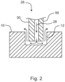
Fig. 2 , a cross-section along the line II-II inFig. 1 is explained in more detail. As depicted inFig. 2 , thebase mold 10 includes themolding feature 12. Themolding feature 12 includes parallel sidewalls and a groove bottom so as to form a recess from a surface of thebase mold 10. Thesealant applicator 26 is inserted into themolding feature 12 and the uncuredwet sealant 28 gets discharged through anozzle member 56 into themolding feature 12. Preferably, the uncuredwet sealant 28 is discharged onto the groove bottom and flows along there towards the parallel sidewalls and rises up towards the surface of thebase mold 10. - The
sealant applicator 26 simultaneously acts as thecomplementary mold member 30 and, preferably due to the relative movement between thecomplementary mold member 30 and thebase mold 10, can shape the uncuredwet sealant 28 to match the portion to be protected of thestructural profile part 14, e.g. into a U-shape. - Since excess of uncured
wet sealant 28 may be flowing from themolding feature 12 between the positive moldemember 30 and the parallel sidewalls onto the surface, the excess may be removed before or after curing. - Referring to
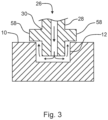
Fig. 3 , a variant of the cross-section is depicted where thecomplementary mold member 30 includes acover portion 58 that prevents excess uncuredwet sealant 28 from exiting themolding feature 12. - Referring to
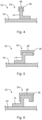
Fig. 4 , a cross-section along line IV-IV inFig. 1 is depicted. Thestructural profile part 14 is fixed to theskin 54 and they cooperatively form part of thefuselage 52. The curedsealant member 38 is attached to a thin edge portion of thestructural profile part 14 such that it is a protectedstructural profile part 50. - Referring to
Fig. 5 and Fig. 6 variants of the cross-section along line IV-IV are depicted. In order to cover the differently shaped portions of thestructural profile part 14, themolding feature 12 can be preferably adapted in width and depth. - In any case, it is preferred that the
molding feature 12 and thecomplementary mold member 30 substantially form a U-shape when they are arranged for application of the uncuredwet sealant 28 and viewed in a cross-section. - In order to improve the manufacture of protected structural profile parts (50), particularly for mass-fabrication for a fuselage (52) of an aircraft, a quasi-continuous process is proposed. A plurality of base molds (10) are prepared by forming molding features (12) that match a portion to be protected of the structural profile part (14). The base molds (10) are arranged such that their molding features (12) cooperatively form a continuous molding feature (16). A sealant applicator (26) is used to apply an uncured wet sealant (28) to the groove, wherein the sealant applicator (26) also acts as a complementary mold member (30) in order to give the uncured wet sealant (28) the desired shape. The wet sealant is cured and forms a cured sealant member (38), which is released from the base mold (10) and fixed to the structural profile part (14) as a protective liner (48), thereby generating the desired protected structural profile part (50).
-
- 10
- base mold
- 12
- molding feature
- 14
- structural profile part
- 16
- continuous molding feature
- 18
- first base mold
- 20
- last base mold
- 22
- intermediate base mold
- 24
- first sealant application mechanism
- 26
- sealant applicator
- 28
- uncured wet sealant
- 30
- complementary mold member
- 32
- separator
- 34
- separated base mold
- 36
- curing apparatus
- 38
- cured sealant member
- 40
- empty base mold
- 42
- second sealant application mechanism
- 44
- uncured self-curing wet sealant
- 46
- second sealant applicator
- 48
- protective liner
- 50
- protected structural profile part
- 52
- fuselage
- 54
- skin
- 56
- nozzle member
- 58
- cover portion
Claims (15)
- A method for manufacturing protective liners (48) for structural profile parts (14) of a fuselage (52) of an aircraft, the method comprising:a) preparing a plurality of base molds (10), wherein each base mold (10) includes a molding feature (12) that matches a portion to be protected of an structural profile part (14);b) arranging the base molds (10) such that their molding features (12) cooperatively form a continuous molding feature (16) from a first base mold (18) to a last base mold (20);c) applying an uncured wet sealant (28) to the continuous molding feature (16);d) curing the uncured wet sealant (28) into a cured sealant member (38) within the base mold (10); ande) releasing the cured sealant member (38) from the base mold (10).
- The method according to claim 1, wherein in step c) a complementary mold member (30) that cooperatively forms a molding cavity with the base mold (10) is applied to the uncured wet sealant (28) in order to generate a profile that matches the portion to be protected.
- The method according to any of the preceding claims, wherein in step c) the uncured wet sealant (28) is applied by moving a sealant applicator (26) and the base molds (10) relative to each other and injecting the uncured wet sealant (28) into the continuous molding feature (16).
- The method according to claim 2 and 3, wherein the sealant applicator (26) includes a nozzle member (56) that is profiled so as to act as the complementary mold member (30) and the matching profile is generated by moving the nozzle member (56) and the base molds (10) relative to each other while simultaneously applying the uncured wet sealant (28).
- The method according to claim 3 or 4, wherein the sealant applicator (26) is stationary and the base molds (10) are moving.
- The method according to any of the preceding claims, wherein in step d) the curing is accelerated by curing the uncured wet sealant (28) in a curing apparatus (36), preferably a curing oven or autoclave.
- The method according to any of the preceding claims, wherein in step d) at least one base mold (10) is separated from its neighboring base mold (10) in order to limit the length of the cured sealant member (38), preferably before inserting the separated base mold (34) into the curing apparatus (36).
- The method according to any of the preceding claims, wherein the method is performed in a continuous manner by performing the steps b) to e) in a cycle, whereby the respective base mold (10) emptied in step e) is arranged to form the continuous molding feature (16) in step b).
- A method for manufacturing a protected structural profile part (50) of a fuselage (52) of an aircraft by performing the method according to any of the previous claims in order to obtain at least one cured sealant member (38) and by attaching the cured sealant member (38) to a structural profile part (14) so as to form a protective liner (48) and generate the protected structural profile part (50).
- The method according to claim 9, wherein the cured sealant member (38) is attached by applying uncured wet sealant (44) and letting it cure.
- A manufacturing apparatus configured for performing a method according to any of the preceding claims, the apparatus comprising:- a plurality of base molds (10), wherein each base mold (10) includes a molding feature (12) that matches a portion to be protected of a structural profile part (14);- a sealant application mechanism (24) that is configured for arranging the base molds (10) such that their molding features (12) cooperatively form a continuous molding feature (16) from a first base mold (18) to a last base mold (20) and for applying an uncured wet sealant (28) to the continuous molding feature (16);- a curing apparatus (36) that is configured for curing the uncured wet sealant (28) into a cured sealant member (38) within the base mold (10); and- a releasing mechanism configured for releasing the cured sealant member (38) from the base mold (10).
- The apparatus according to claim 11, wherein the sealant application mechanism (24) comprises:- a complementary mold member (30) that is configured to be applied to the uncured wet sealant (28) in order to generate a profile that matches the portion to be protected; and/or- a sealant applicator (26) that is configured for injecting the uncured wet sealant (28) into the continuous molding feature (16), wherein the sealant applicator (26) and the base molds (10) are movable relative to each other.
- The apparatus according to claim 12,- wherein the sealant applicator (26) includes a nozzle member (56) that is profiled so as to act as the complementary mold member (30) and configured for generating the matching profile by moving the nozzle member (56) and the base molds (10) relative to each other while simultaneously applying the uncured wet sealant (28); and/or- wherein the sealant applicator (26) is stationary and the base molds (10) are movable.
- The apparatus according to any of the claims 11 to 13, the apparatus further comprising:- a curing apparatus (36), preferably a curing oven or an autoclave, configured for curing the uncured wet sealant (28); and/or- an automatic or manual transport device that is configured for transporting the base molds (10) between different stations of the manufacturing apparatus; and/or- a second sealant applicator (46) that is configured for applying uncured wet sealant (44) so as to attach the cured sealant member (38) to the structural profile part (14) as a protective liner (48).
- The apparatus according to claim 14,- wherein the automatic transport device is configured to automatically separate at least one base mold (10) from its neighboring base mold (10) in order to limit the length of the cured sealant member (38), preferably before transporting and inserting the separated base mold (34) into the curing apparatus (36); and/or- wherein the automatic transport device is configured so as to allow performance of the steps b) to e) in a cycle, whereby the respective base mold (10) emptied in step e) is arranged to form the continuous molding feature (16) in step b), in order to perform the manufacturing method in a continuous manner.
Priority Applications (1)
| Application Number | Priority Date | Filing Date | Title |
|---|---|---|---|
| EP23171455.1A EP4458544B1 (en) | 2023-05-04 | 2023-05-04 | A method and apparatus for manufacturing protective liners for structural profile parts of aircraft |
Applications Claiming Priority (1)
| Application Number | Priority Date | Filing Date | Title |
|---|---|---|---|
| EP23171455.1A EP4458544B1 (en) | 2023-05-04 | 2023-05-04 | A method and apparatus for manufacturing protective liners for structural profile parts of aircraft |
Publications (2)
| Publication Number | Publication Date |
|---|---|
| EP4458544A1 true EP4458544A1 (en) | 2024-11-06 |
| EP4458544B1 EP4458544B1 (en) | 2025-12-10 |
Family
ID=86329724
Family Applications (1)
| Application Number | Title | Priority Date | Filing Date |
|---|---|---|---|
| EP23171455.1A Active EP4458544B1 (en) | 2023-05-04 | 2023-05-04 | A method and apparatus for manufacturing protective liners for structural profile parts of aircraft |
Country Status (1)
| Country | Link |
|---|---|
| EP (1) | EP4458544B1 (en) |
Citations (9)
| Publication number | Priority date | Publication date | Assignee | Title |
|---|---|---|---|---|
| US2166798A (en) * | 1937-07-17 | 1939-07-18 | Cote Marcellin | Method of applying guards or bumpers |
| EP1860250A2 (en) | 2006-05-26 | 2007-11-28 | Raico Bautechnik GmbH | Attachment seal |
| EP2176123A1 (en) | 2007-08-08 | 2010-04-21 | Airbus Operations Ltd | Composite laminate structure |
| WO2014184692A1 (en) * | 2013-05-17 | 2014-11-20 | K-Holding S.P.A. | Process and apparatus for bordering a corrugated plastic panel and panel thus obtained |
| EP2839946A2 (en) | 2013-08-20 | 2015-02-25 | The Boeing Company | Transfer System and Method for Applying a Film Material to an Elongate Member |
| DE102014017411A1 (en) | 2014-11-26 | 2016-06-02 | Airbus Defence and Space GmbH | Fiber composite components with edge protection |
| US20170152949A1 (en) | 2015-11-30 | 2017-06-01 | The Boeing Company | Sealant containment assembly, system, and method |
| EP3205470A1 (en) | 2016-02-11 | 2017-08-16 | Institut de Recherche Technologique Jules VERNE | A device and process for manufacturing a part having an insert, by injection overmolding and a commande system for such a device |
| GB2588967A (en) | 2019-11-18 | 2021-05-19 | Airbus Operations Ltd | Aircraft structure having a composite laminate body and edge cap device |
-
2023
- 2023-05-04 EP EP23171455.1A patent/EP4458544B1/en active Active
Patent Citations (9)
| Publication number | Priority date | Publication date | Assignee | Title |
|---|---|---|---|---|
| US2166798A (en) * | 1937-07-17 | 1939-07-18 | Cote Marcellin | Method of applying guards or bumpers |
| EP1860250A2 (en) | 2006-05-26 | 2007-11-28 | Raico Bautechnik GmbH | Attachment seal |
| EP2176123A1 (en) | 2007-08-08 | 2010-04-21 | Airbus Operations Ltd | Composite laminate structure |
| WO2014184692A1 (en) * | 2013-05-17 | 2014-11-20 | K-Holding S.P.A. | Process and apparatus for bordering a corrugated plastic panel and panel thus obtained |
| EP2839946A2 (en) | 2013-08-20 | 2015-02-25 | The Boeing Company | Transfer System and Method for Applying a Film Material to an Elongate Member |
| DE102014017411A1 (en) | 2014-11-26 | 2016-06-02 | Airbus Defence and Space GmbH | Fiber composite components with edge protection |
| US20170152949A1 (en) | 2015-11-30 | 2017-06-01 | The Boeing Company | Sealant containment assembly, system, and method |
| EP3205470A1 (en) | 2016-02-11 | 2017-08-16 | Institut de Recherche Technologique Jules VERNE | A device and process for manufacturing a part having an insert, by injection overmolding and a commande system for such a device |
| GB2588967A (en) | 2019-11-18 | 2021-05-19 | Airbus Operations Ltd | Aircraft structure having a composite laminate body and edge cap device |
Also Published As
| Publication number | Publication date |
|---|---|
| EP4458544B1 (en) | 2025-12-10 |
Similar Documents
| Publication | Publication Date | Title |
|---|---|---|
| US10377064B2 (en) | Apparatus and method for continuously manufacturing components from fiber-reinforced composites, and mold set | |
| US9498903B2 (en) | System and method for manufacturing monolithic structures using expanding internal tools | |
| EP2043832B1 (en) | Method for producing a fibre composite component using a moulding core, and said moulding core | |
| US12157280B2 (en) | Multi-stage resin delivery | |
| FI80848B (en) | Method for the manufacture of a mould set | |
| US9067345B2 (en) | Mold for manufacture of fiber composite parts and method of manufacture of fiber composite parts with such a mold | |
| CN106275370B (en) | Reinforced fuselage component and method and device for producing a reinforced fuselage component | |
| CN105555510A (en) | Method of forming a composite member and assembly therefor | |
| WO2019074916A2 (en) | Composite material inlay in additively manufactured structures | |
| CN101801649A (en) | Method and tooling for fabricating composite structures | |
| US12350776B2 (en) | Composite assembly for unhardened fuselage components | |
| EP3112116B1 (en) | Methods of manufacturing panels of composite material reinforced with closed-section stringers | |
| EP4458544B1 (en) | A method and apparatus for manufacturing protective liners for structural profile parts of aircraft | |
| EP4234394B1 (en) | Aircrraft comprising composite structural component, and method for forming composite structural component | |
| EP4000841B1 (en) | Composite assembly for unhardened fuselage components | |
| US11390045B2 (en) | Molding assembly and method of co-curing stiffener with panel | |
| EP4442444A1 (en) | A method for protecting a profile structural part of an aircraft against mechanical wear and/or mechanical impact | |
| EP4442441A1 (en) | A method for in-situ manufacturing a protective liner on an elongated structural part of an aircraft | |
| DE102023127254A1 (en) | Method for producing a leading edge and an aerodynamic profile body |
Legal Events
| Date | Code | Title | Description |
|---|---|---|---|
| PUAI | Public reference made under article 153(3) epc to a published international application that has entered the european phase |
Free format text: ORIGINAL CODE: 0009012 |
|
| STAA | Information on the status of an ep patent application or granted ep patent |
Free format text: STATUS: THE APPLICATION HAS BEEN PUBLISHED |
|
| AK | Designated contracting states |
Kind code of ref document: A1 Designated state(s): AL AT BE BG CH CY CZ DE DK EE ES FI FR GB GR HR HU IE IS IT LI LT LU LV MC ME MK MT NL NO PL PT RO RS SE SI SK SM TR |
|
| STAA | Information on the status of an ep patent application or granted ep patent |
Free format text: STATUS: REQUEST FOR EXAMINATION WAS MADE |
|
| 17P | Request for examination filed |
Effective date: 20250310 |
|
| GRAP | Despatch of communication of intention to grant a patent |
Free format text: ORIGINAL CODE: EPIDOSNIGR1 |
|
| STAA | Information on the status of an ep patent application or granted ep patent |
Free format text: STATUS: GRANT OF PATENT IS INTENDED |
|
| INTG | Intention to grant announced |
Effective date: 20250711 |
|
| GRAS | Grant fee paid |
Free format text: ORIGINAL CODE: EPIDOSNIGR3 |
|
| GRAA | (expected) grant |
Free format text: ORIGINAL CODE: 0009210 |
|
| STAA | Information on the status of an ep patent application or granted ep patent |
Free format text: STATUS: THE PATENT HAS BEEN GRANTED |
|
| AK | Designated contracting states |
Kind code of ref document: B1 Designated state(s): AL AT BE BG CH CY CZ DE DK EE ES FI FR GB GR HR HU IE IS IT LI LT LU LV MC ME MK MT NL NO PL PT RO RS SE SI SK SM TR |
|
| REG | Reference to a national code |
Ref country code: CH Ref legal event code: F10 Free format text: ST27 STATUS EVENT CODE: U-0-0-F10-F00 (AS PROVIDED BY THE NATIONAL OFFICE) Effective date: 20251210 Ref country code: GB Ref legal event code: FG4D |
|
| REG | Reference to a national code |
Ref country code: DE Ref legal event code: R096 Ref document number: 602023009439 Country of ref document: DE |
|
| REG | Reference to a national code |
Ref country code: IE Ref legal event code: FG4D |
|
| PG25 | Lapsed in a contracting state [announced via postgrant information from national office to epo] |
Ref country code: ES Free format text: LAPSE BECAUSE OF FAILURE TO SUBMIT A TRANSLATION OF THE DESCRIPTION OR TO PAY THE FEE WITHIN THE PRESCRIBED TIME-LIMIT Effective date: 20251210 |
|
| REG | Reference to a national code |
Ref country code: LT Ref legal event code: MG9D |
|
| PG25 | Lapsed in a contracting state [announced via postgrant information from national office to epo] |
Ref country code: NO Free format text: LAPSE BECAUSE OF FAILURE TO SUBMIT A TRANSLATION OF THE DESCRIPTION OR TO PAY THE FEE WITHIN THE PRESCRIBED TIME-LIMIT Effective date: 20260310 |
|
| PG25 | Lapsed in a contracting state [announced via postgrant information from national office to epo] |
Ref country code: FI Free format text: LAPSE BECAUSE OF FAILURE TO SUBMIT A TRANSLATION OF THE DESCRIPTION OR TO PAY THE FEE WITHIN THE PRESCRIBED TIME-LIMIT Effective date: 20251210 Ref country code: HR Free format text: LAPSE BECAUSE OF FAILURE TO SUBMIT A TRANSLATION OF THE DESCRIPTION OR TO PAY THE FEE WITHIN THE PRESCRIBED TIME-LIMIT Effective date: 20251210 |
|
| REG | Reference to a national code |
Ref country code: NL Ref legal event code: MP Effective date: 20251210 |
|
| PG25 | Lapsed in a contracting state [announced via postgrant information from national office to epo] |
Ref country code: RS Free format text: LAPSE BECAUSE OF FAILURE TO SUBMIT A TRANSLATION OF THE DESCRIPTION OR TO PAY THE FEE WITHIN THE PRESCRIBED TIME-LIMIT Effective date: 20260310 |
|
| PG25 | Lapsed in a contracting state [announced via postgrant information from national office to epo] |
Ref country code: LV Free format text: LAPSE BECAUSE OF FAILURE TO SUBMIT A TRANSLATION OF THE DESCRIPTION OR TO PAY THE FEE WITHIN THE PRESCRIBED TIME-LIMIT Effective date: 20251210 |
|
| PG25 | Lapsed in a contracting state [announced via postgrant information from national office to epo] |
Ref country code: BG Free format text: LAPSE BECAUSE OF FAILURE TO SUBMIT A TRANSLATION OF THE DESCRIPTION OR TO PAY THE FEE WITHIN THE PRESCRIBED TIME-LIMIT Effective date: 20251210 |