EP4458543A1 - Hopper comprising a vibrating device, and calendering system comprising such a hopper - Google Patents
Hopper comprising a vibrating device, and calendering system comprising such a hopper Download PDFInfo
- Publication number
- EP4458543A1 EP4458543A1 EP23315170.3A EP23315170A EP4458543A1 EP 4458543 A1 EP4458543 A1 EP 4458543A1 EP 23315170 A EP23315170 A EP 23315170A EP 4458543 A1 EP4458543 A1 EP 4458543A1
- Authority
- EP
- European Patent Office
- Prior art keywords
- hopper
- powder
- calender rollers
- vibrating
- hopper body
- Prior art date
- Legal status (The legal status is an assumption and is not a legal conclusion. Google has not performed a legal analysis and makes no representation as to the accuracy of the status listed.)
- Granted
Links
Images


Classifications
-
- B—PERFORMING OPERATIONS; TRANSPORTING
- B29—WORKING OF PLASTICS; WORKING OF SUBSTANCES IN A PLASTIC STATE IN GENERAL
- B29C—SHAPING OR JOINING OF PLASTICS; SHAPING OF MATERIAL IN A PLASTIC STATE, NOT OTHERWISE PROVIDED FOR; AFTER-TREATMENT OF THE SHAPED PRODUCTS, e.g. REPAIRING
- B29C43/00—Compression moulding, i.e. applying external pressure to flow the moulding material; Apparatus therefor
- B29C43/003—Compression moulding, i.e. applying external pressure to flow the moulding material; Apparatus therefor characterised by the choice of material
-
- B—PERFORMING OPERATIONS; TRANSPORTING
- B29—WORKING OF PLASTICS; WORKING OF SUBSTANCES IN A PLASTIC STATE IN GENERAL
- B29C—SHAPING OR JOINING OF PLASTICS; SHAPING OF MATERIAL IN A PLASTIC STATE, NOT OTHERWISE PROVIDED FOR; AFTER-TREATMENT OF THE SHAPED PRODUCTS, e.g. REPAIRING
- B29C31/00—Handling, e.g. feeding of the material to be shaped, storage of plastics material before moulding; Automation, i.e. automated handling lines in plastics processing plants, e.g. using manipulators or robots
- B29C31/02—Dispensing from vessels, e.g. hoppers
-
- B—PERFORMING OPERATIONS; TRANSPORTING
- B29—WORKING OF PLASTICS; WORKING OF SUBSTANCES IN A PLASTIC STATE IN GENERAL
- B29C—SHAPING OR JOINING OF PLASTICS; SHAPING OF MATERIAL IN A PLASTIC STATE, NOT OTHERWISE PROVIDED FOR; AFTER-TREATMENT OF THE SHAPED PRODUCTS, e.g. REPAIRING
- B29C43/00—Compression moulding, i.e. applying external pressure to flow the moulding material; Apparatus therefor
- B29C43/22—Compression moulding, i.e. applying external pressure to flow the moulding material; Apparatus therefor of articles of indefinite length
- B29C43/24—Calendering
-
- B—PERFORMING OPERATIONS; TRANSPORTING
- B29—WORKING OF PLASTICS; WORKING OF SUBSTANCES IN A PLASTIC STATE IN GENERAL
- B29C—SHAPING OR JOINING OF PLASTICS; SHAPING OF MATERIAL IN A PLASTIC STATE, NOT OTHERWISE PROVIDED FOR; AFTER-TREATMENT OF THE SHAPED PRODUCTS, e.g. REPAIRING
- B29C43/00—Compression moulding, i.e. applying external pressure to flow the moulding material; Apparatus therefor
- B29C43/32—Component parts, details or accessories; Auxiliary operations
- B29C43/34—Feeding the material to the mould or the compression means
-
- B—PERFORMING OPERATIONS; TRANSPORTING
- B29—WORKING OF PLASTICS; WORKING OF SUBSTANCES IN A PLASTIC STATE IN GENERAL
- B29C—SHAPING OR JOINING OF PLASTICS; SHAPING OF MATERIAL IN A PLASTIC STATE, NOT OTHERWISE PROVIDED FOR; AFTER-TREATMENT OF THE SHAPED PRODUCTS, e.g. REPAIRING
- B29C43/00—Compression moulding, i.e. applying external pressure to flow the moulding material; Apparatus therefor
- B29C43/32—Component parts, details or accessories; Auxiliary operations
- B29C43/34—Feeding the material to the mould or the compression means
- B29C2043/3433—Feeding the material to the mould or the compression means using dispensing heads, e.g. extruders, placed over or apart from the moulds
- B29C2043/3438—Feeding the material to the mould or the compression means using dispensing heads, e.g. extruders, placed over or apart from the moulds moving during dispensing over the moulds, e.g. laying up
-
- B—PERFORMING OPERATIONS; TRANSPORTING
- B29—WORKING OF PLASTICS; WORKING OF SUBSTANCES IN A PLASTIC STATE IN GENERAL
- B29C—SHAPING OR JOINING OF PLASTICS; SHAPING OF MATERIAL IN A PLASTIC STATE, NOT OTHERWISE PROVIDED FOR; AFTER-TREATMENT OF THE SHAPED PRODUCTS, e.g. REPAIRING
- B29C43/00—Compression moulding, i.e. applying external pressure to flow the moulding material; Apparatus therefor
- B29C43/32—Component parts, details or accessories; Auxiliary operations
- B29C43/34—Feeding the material to the mould or the compression means
- B29C2043/3488—Feeding the material to the mould or the compression means uniformly distributed into the mould
- B29C2043/3494—Feeding the material to the mould or the compression means uniformly distributed into the mould using vibrating means
Definitions
- the present invention relates to a hopper, and to a calendering system comprising two parallel calender rollers and such a hopper.
- Calendering is a speciality process for high-volume, high quality plastic film and sheet, mainly used for PVC (polyvinyl chloride) as well as for certain other modified thermoplastics.
- a calendering system operates by passing a material between two contra-rotating parallel rollers to smooth or gloss it, or to produce a film or a sheet.
- the material can be an electrically conductive mixture (for example in powder form), and the calendaring system participate to fabricate electrodes for electrochemical cells (by forming a film at the outlet of the rollers by calendering).
- Calendering systems thereby comprising two parallel calender rollers and a hopper, are known in the art.
- the hopper classically comprises a hopper body which contains powder and is arranged above the two parallel calender rollers so as to supply with powder an interspace between the two parallel calender rollers.
- the hopper body defines an internal housing at atmospheric pressure in which powder is stored.
- Such a calendering system may further comprise a device for feeding powder into the interspace between the two calender rollers.
- Such a device uses mechanical parts (screw, brush, stirrer...) for drain matter. However, the matter may fall into the interspace without any control about the matter which is already present (open loop).
- the mechanical parts which are used in such a device introduce a high risk of powder fibrillation. This action can make obstruction and hence causes the system to collapse. Last but not least, there is no compensation in the device when matter is not regularly fed, and matter holes are likely to appear.
- the calendering system further comprises a vibrating device.
- the patent document CN 114744145 A discloses for example such a calendering system.
- the vibrating device is an ultrasonic vibrating device which is provided on an outer side wall of a material guide channel arranged beneath the hopper, and which can adjust the discharge speed and discharge density, to ensure smooth feeding of materials and to allow control of the discharge of the material guide channel.
- Patent document EP 1 800 775 A1 also discloses such a calendering system in which the hopper comprises a vibrating device provided on an outer side wall of the hopper to control the weight of the electrically conductive mixture in the hopper.
- vibration calendering systems are not sufficient to avoid the formation of material domes in powder (due to powder cohesion), which can lead to a lack of material at the rollers interspace, resulting in the formation of an inhomogeneous film at the outlet of the rollers.
- the object of the present invention is therefore to overcome the drawbacks of the prior art by providing a hopper for a calendering system which avoids formation of material domes in powder stored in the hopper, so as to prevent lack of material at the rollers interspace and formation of an inhomogeneous film at the outlet of the rollers, while avoiding powder fibrillation.
- a hopper comprising a hopper body containing powder, said hopper body defining an internal housing in which said powder is stored, the hopper further comprising a vibrating device, said vibrating device being provided with a vibrating generator, said vibrating device being further provided with a shaft coupled to said vibrating generator; the vibrating device being arranged such that the shaft is inserted into powder; and the hopper further comprising at least one grid, said at least one grid being arranged within said housing of the hopper body, being secured to the shaft and being configured to brake powder domes when they occur.
- said vibrating generator is a piezo actuator or an electromechanical vibration generator.
- the vibrating device is arranged such that the shaft is inserted into powder along a direction substantially parallel to a main direction of extension of the hopper body.
- said longitudinal direction is a vertical direction.
- said vibrating generator is configured to transmit a longitudinal vibration motion to the shaft, the amplitude of which is about 0.1 mm and the frequency of which is comprised between 5 Hz and 50Hz.
- Such a configuration of the vibrating generator allows to transmit very short and low energy motion to the shaft. This low energy motion helps to brake powder domes and powder cohesion, and to respect the nature of the fibrillating matter because there is no high energy motion within powder.
- the hopper body comprises a funnel-shaped bottom end portion and a nose extending said funnel-shaped bottom end portion downwards, said nose facing the two parallel calender rollers.
- a configuration for the hopper body (which is very similar to that of an "up-side-down" bottle) allows to use gravity as a major force to generate powder stream from the middle-top of the hopper body to the nose.
- the nose allows to guide powder and to feed the interspace between the two calender rollers properly. The empty interspace is thereby filled up spontaneously with powder by gravity.
- the hopper comprises a vertical grid arranged within said nose.
- This vertical grid also acts as a "dome avoider", which further helps to brake powder cohesion, and increases the homogeneity of powder which flows out of the nose.
- the internal housing is at atmospheric pressure.
- the hopper comprises at least one horizontal grid arranged within the housing of the hopper body.
- a calendering system comprising two parallel calender rollers and such a hopper, the two parallel calender rollers defining an interspace between them, the hopper body of the hopper being arranged above the two parallel calender rollers so as to supply with powder said interspace between the two parallel calender rollers.
- the calendering system according to the invention allows to have a continuous feeding without hole (needed matter) in calendering input by gravity effect, or gravity "auto-compensation" (i.e., if powder is missing in the interspace between the two rollers, powder present in the hopper falls automatically just as sand would do in a reversed bottle).
- the calendering system according to the invention also avoids powder fibrillation, because there are no motion mechanical parts in contact with powder, and has a further advantage which lies in that no transportation is needed between the dosing device of the system and the calender input.
- the hopper body is mounted movable in longitudinal translation relative to the two parallel calender rollers
- the calendering system further comprises means for controlling the longitudinal translation movement of the hopper relative to the two parallel calender rollers. This allows to set a precise distance between the nose (i.e. the bottom end of the hopper body) and the rollers, and to feed thereby the right quantity of powder to the rollers, making it possible to adjust precisely the quantity of powder delivered to said rollers.
- the calendering system further comprises at least one actuator or one cylinder which is configured to move the hopper body in longitudinal translation relative to the two parallel calender rollers.
- FIG. 1 an orthonormal frame X-Y-Z is shown.
- the vertical direction designates the direction parallel to the Z axis
- the horizontal direction designates any direction perpendicular to the vertical direction, in other words any direction contained in the X-Y plane.
- the longitudinal direction A-A' designates the main direction of extension of the hopper body.
- a transverse direction designates any direction perpendicular to the longitudinal direction.
- the longitudinal direction corresponds to the vertical direction.
- a calendering system 2 comprises two parallel calender rollers 4 and a hopper 6.
- the calendering system 2 further comprises means 8 for controlling a longitudinal translation movement (i.e. a linear movement along the vertical direction) of the hopper 6 relative to the two parallel calender rollers 4, and an actuator or cylinder 10.
- the two parallel calender rollers 4 define an interspace 12 between them.
- the hopper 6 classicaly comprises a hopper body 14 containing powder 16 and arranged above the two parallel calender rollers 4 so as to supply with powder 16 the interspace 12 between the two parallel calender rollers 4.
- the hopper body 14 is conventionally provided with a bottom opening 18 arranged facing the interspace 12, above it. More precisely, in the particular embodiment of Figures 1 to 5 , the hopper body 14 comprises a funnel-shaped bottom end portion 20 and a nose 22 (which is provided with the bottom opening 18).
- the nose 22 extends the funnel-shaped bottom end portion 20 downwards and is arranged facing the two parallel calender rollers 4, more particularly the interspace 12 between them.
- Such a configuration for the hopper body 14 (which is very similar to that of an "up-side-down" bottle) allows to use gravity as a major force to generate powder stream from the middle-top of the hopper body 14 to the nose 22.
- the empty interspace 12 is thereby filled up spontaneously with powder 16 by gravity.
- the hopper body 14 defines an internal housing 24 at atmospheric pressure in which powder 16 is stored.
- Powder 16 is for example an electrically conductive mixture, and/or a thermoplastic powder.
- the hopper body 14 (and the nose 22, more particularly) follows the calender rollers size without any width limitation (the width of the nose 22 corresponding to the length of the calender rollers 4 and being measured along the X axis).
- the hopper 6 further comprises a vibrating device 26 and at least one grid 28A, 28B, 28C.
- the hopper 6 comprises three grids 28A, 28B, 28C, namely one vertical grid 28A and two horizontal grids 28B, 28C.
- the vibrating device 26 includes a vibrating generator 30 and a shaft 32 coupled to the vibrating generator 30.
- the vibrating device 26 is arranged such that the shaft 32 is inserted into powder 16 along the longitudinal direction A-A'.
- the vibrating generator 30 is configured to transmit a longitudinal vibration motion to the shaft 32, the amplitude of which is about 0.1 mm and the frequency of which is comprised between 5 Hz and 50Hz.
- the vibrating generator 30 is a piezo actuator or an electromechanical vibration generator.
- the vibrating generator 30 may advantageously be configured such that the amplitude and the frequency of the longitudinal vibration motion it transmits to the shaft 32 be adjustable according to the quantity of powder 16 stored in the hopper body 14.
- Each grid 28A, 28B, 28C is arranged within the housing 24 of the hopper body 14, is secured to the shaft 32 and is configured to brake powder domes when they occur.
- the vertical grid 28A is arranged within the nose 22 and extends in the vertical X-Z plane.
- Each of the two horizontal grids 28B, 28C extends in the horizontal X-Y plane.
- An upper grid 28B is arranged above a lower grid 28C within the housing 24 of the hopper body 14.
- the hopper body 14 is mounted movable in longitudinal translation relative to the two parallel calender rollers 4.
- the controlling means 8 then allow to control the longitudinal translation of the hopper body 14 (i.e. along the vertical Z axis in the illustrated embodiment) in the direction of the arrows F1, F2 in Figures 3 and 5 , with an absolute ground reference. More precisely, the controlling means 8 are electrically connected to the actuator or cylinder 10, said actuator or cylinder 10 being connected to the hopper body 14 so as to move the hopper body 14 in longitudinal translation relative to the two parallel calender rollers 4.
- powder 16 which is present in the hopper body 14 falls through the nose 22 and spontaneously creates a powder nip 16A at the interspace 12 between the two calender rollers 4.
- the coupling between the vibrating device 26 and the grids 28A, 28B, 28C enables to brake powder domes when they occur.
- the low energy vibrating motion which is transmitted by the vibrating generator 30 to the shaft 32 forces powder particles to roll on top of each other. This energy brakes powder cohesion and establishes something very similar to a "liquid state".
- This configuration thus acts as a "dome avoider" which allows powder 16 to flow continuously and homogeneously from the main hopper capacity to the nose 22 of the hopper body 14.
- the powder stream stops from itself without any action, by physical saturation.
- matter disappears and creates a hole due to the calender rollers consumption
- the powder stream appears again spontaneously because it has created an empty zone, and the gravity force becomes higher than the empty zone force. The cycle is then repeated.
- This calendering system 2 allows the hopper 6 to distribute the right quantity of powder 16 to the two parallel calender rollers 4.
- the height of the hopper body 14 is driven by slide motion by the controlling means 8 (up/down motion along the arrows F1, F2 in Figures 3 and 5 ).
- the calendering system 2 according to the invention ensures homogeneous powder distribution through gravity and vibration actions, in any dimension.
Landscapes
- Engineering & Computer Science (AREA)
- Mechanical Engineering (AREA)
- Robotics (AREA)
- Filling Or Emptying Of Bunkers, Hoppers, And Tanks (AREA)
Abstract
Description
- The present invention relates to a hopper, and to a calendering system comprising two parallel calender rollers and such a hopper.
- Calendering is a speciality process for high-volume, high quality plastic film and sheet, mainly used for PVC (polyvinyl chloride) as well as for certain other modified thermoplastics. A calendering system operates by passing a material between two contra-rotating parallel rollers to smooth or gloss it, or to produce a film or a sheet. In some particular applications, the material can be an electrically conductive mixture (for example in powder form), and the calendaring system participate to fabricate electrodes for electrochemical cells (by forming a film at the outlet of the rollers by calendering).
- Calendering systems thereby comprising two parallel calender rollers and a hopper, are known in the art. The hopper classically comprises a hopper body which contains powder and is arranged above the two parallel calender rollers so as to supply with powder an interspace between the two parallel calender rollers. The hopper body defines an internal housing at atmospheric pressure in which powder is stored. Such a calendering system may further comprise a device for feeding powder into the interspace between the two calender rollers. Such a device uses mechanical parts (screw, brush, stirrer...) for drain matter. However, the matter may fall into the interspace without any control about the matter which is already present (open loop). Besides, the mechanical parts which are used in such a device introduce a high risk of powder fibrillation. This action can make obstruction and hence causes the system to collapse. Last but not least, there is no compensation in the device when matter is not regularly fed, and matter holes are likely to appear.
- In order to overcome the above-mentioned drawbacks, some solutions have been developed in which the calendering system further comprises a vibrating device. The patent document
CN 114744145 A discloses for example such a calendering system. The vibrating device is an ultrasonic vibrating device which is provided on an outer side wall of a material guide channel arranged beneath the hopper, and which can adjust the discharge speed and discharge density, to ensure smooth feeding of materials and to allow control of the discharge of the material guide channel. Patent documentEP 1 800 775 A1 also discloses such a calendering system in which the hopper comprises a vibrating device provided on an outer side wall of the hopper to control the weight of the electrically conductive mixture in the hopper. - However, such vibration calendering systems are not sufficient to avoid the formation of material domes in powder (due to powder cohesion), which can lead to a lack of material at the rollers interspace, resulting in the formation of an inhomogeneous film at the outlet of the rollers.
- A need therefore exists for a hopper for a calendering system, such a hopper avoiding formation of such material domes in powder stored in the hopper.
- The object of the present invention is therefore to overcome the drawbacks of the prior art by providing a hopper for a calendering system which avoids formation of material domes in powder stored in the hopper, so as to prevent lack of material at the rollers interspace and formation of an inhomogeneous film at the outlet of the rollers, while avoiding powder fibrillation.
- According to a first aspect of the invention, there is provided a hopper comprising a hopper body containing powder, said hopper body defining an internal housing in which said powder is stored, the hopper further comprising a vibrating device, said vibrating device being provided with a vibrating generator, said vibrating device being further provided with a shaft coupled to said vibrating generator; the vibrating device being arranged such that the shaft is inserted into powder; and the hopper further comprising at least one grid, said at least one grid being arranged within said housing of the hopper body, being secured to the shaft and being configured to brake powder domes when they occur.
- The coupling between a vibrating device thus configured and the presence of at least one grid secured to the shaft enables to brake powder domes when they occur. Indeed, the vibrating motion which is transmitted by the vibrating generator to the shaft forces powder particles to roll on top of each other. This energy brakes powder cohesion and establishes something very similar to a "liquid state". This configuration thus acts as a "dome avoider" which allows powder to flow continuously and homogeneously from the main hopper capacity to the bottom end of the hopper body (nose of the hopper body).
- In a particular embodiment of the invention, said vibrating generator is a piezo actuator or an electromechanical vibration generator.
- In another particular embodiment of the invention, the vibrating device is arranged such that the shaft is inserted into powder along a direction substantially parallel to a main direction of extension of the hopper body.
- In a preferred embodiment, said longitudinal direction is a vertical direction.
- In another preferred embodiment, said vibrating generator is configured to transmit a longitudinal vibration motion to the shaft, the amplitude of which is about 0.1 mm and the frequency of which is comprised between 5 Hz and 50Hz.
- Such a configuration of the vibrating generator allows to transmit very short and low energy motion to the shaft. This low energy motion helps to brake powder domes and powder cohesion, and to respect the nature of the fibrillating matter because there is no high energy motion within powder.
- In a particular embodiment of the invention, the hopper body comprises a funnel-shaped bottom end portion and a nose extending said funnel-shaped bottom end portion downwards, said nose facing the two parallel calender rollers. Such a configuration for the hopper body (which is very similar to that of an "up-side-down" bottle) allows to use gravity as a major force to generate powder stream from the middle-top of the hopper body to the nose. The nose allows to guide powder and to feed the interspace between the two calender rollers properly. The empty interspace is thereby filled up spontaneously with powder by gravity.
- In a preferred embodiment, the hopper comprises a vertical grid arranged within said nose. This vertical grid also acts as a "dome avoider", which further helps to brake powder cohesion, and increases the homogeneity of powder which flows out of the nose.
- In a particular embodiment of the invention, the internal housing is at atmospheric pressure.
- In another particular embodiment of the invention, the hopper comprises at least one horizontal grid arranged within the housing of the hopper body.
- The above-mentioned embodiments can be combined.
- According to a second aspect of the invention, there is provided a calendering system comprising two parallel calender rollers and such a hopper, the two parallel calender rollers defining an interspace between them, the hopper body of the hopper being arranged above the two parallel calender rollers so as to supply with powder said interspace between the two parallel calender rollers.
- Thanks to the particular configuration of the hopper, the calendering system according to the invention allows to have a continuous feeding without hole (needed matter) in calendering input by gravity effect, or gravity "auto-compensation" (i.e., if powder is missing in the interspace between the two rollers, powder present in the hopper falls automatically just as sand would do in a reversed bottle). The calendering system according to the invention also avoids powder fibrillation, because there are no motion mechanical parts in contact with powder, and has a further advantage which lies in that no transportation is needed between the dosing device of the system and the calender input.
- In a preferred embodiment, the hopper body is mounted movable in longitudinal translation relative to the two parallel calender rollers, and the calendering system further comprises means for controlling the longitudinal translation movement of the hopper relative to the two parallel calender rollers. This allows to set a precise distance between the nose (i.e. the bottom end of the hopper body) and the rollers, and to feed thereby the right quantity of powder to the rollers, making it possible to adjust precisely the quantity of powder delivered to said rollers.
- In a particular embodiment of the invention, the calendering system further comprises at least one actuator or one cylinder which is configured to move the hopper body in longitudinal translation relative to the two parallel calender rollers.
- Other advantages and features of the invention will become more readily apparent from the following description of a specific embodiment of the invention. The specific embodiment of the present invention as set forth is given as a non-restrictive example only and represented in the accompanying drawings, in which:
-
figure 1 is a perspective view of a calendering system according to an embodiment of the present invention, the calendering system comprising two parallel calender rollers and a hopper; -
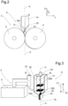
figure 2 is a front view of the calendering system offigure 1 ; -
figure 3 is a perspective view showing the hopper offigure 1 and means for controlling a longitudinal translation movement of the hopper; -
figure 4 is a perspective view of the hopper offigure 1 ; and -
figure 5 is an enlarged perspective view showing an embodiment detail of the calendering system offigure 1 . - Corresponding reference numerals refer to the same or corresponding parts in each of the figures. In
figures 1 and2 an orthonormal frame X-Y-Z is shown. In the following description, the vertical direction designates the direction parallel to the Z axis, and the horizontal direction designates any direction perpendicular to the vertical direction, in other words any direction contained in the X-Y plane. Furthermore, the longitudinal direction A-A' designates the main direction of extension of the hopper body. A transverse direction designates any direction perpendicular to the longitudinal direction. In the particular embodiment shown infigures 1 to 5 , the longitudinal direction corresponds to the vertical direction. - With reference to
Figures 1 to 3 , acalendering system 2 comprises twoparallel calender rollers 4 and ahopper 6. Preferably, as shown inFigure 3 , thecalendering system 2 further comprisesmeans 8 for controlling a longitudinal translation movement (i.e. a linear movement along the vertical direction) of thehopper 6 relative to the twoparallel calender rollers 4, and an actuator orcylinder 10. - As shown in
Figures 1 ,2 and5 , the twoparallel calender rollers 4 define aninterspace 12 between them. Thehopper 6 classicaly comprises ahopper body 14 containingpowder 16 and arranged above the twoparallel calender rollers 4 so as to supply withpowder 16 theinterspace 12 between the twoparallel calender rollers 4. To this end, thehopper body 14 is conventionally provided with abottom opening 18 arranged facing theinterspace 12, above it. More precisely, in the particular embodiment ofFigures 1 to 5 , thehopper body 14 comprises a funnel-shapedbottom end portion 20 and a nose 22 (which is provided with the bottom opening 18). Thenose 22 extends the funnel-shapedbottom end portion 20 downwards and is arranged facing the twoparallel calender rollers 4, more particularly theinterspace 12 between them. Such a configuration for the hopper body 14 (which is very similar to that of an "up-side-down" bottle) allows to use gravity as a major force to generate powder stream from the middle-top of thehopper body 14 to thenose 22. Theempty interspace 12 is thereby filled up spontaneously withpowder 16 by gravity. - The
hopper body 14 defines aninternal housing 24 at atmospheric pressure in whichpowder 16 is stored.Powder 16 is for example an electrically conductive mixture, and/or a thermoplastic powder. As shown inFigure 1 , the hopper body 14 (and thenose 22, more particularly) follows the calender rollers size without any width limitation (the width of thenose 22 corresponding to the length of thecalender rollers 4 and being measured along the X axis). - The
hopper 6 further comprises a vibratingdevice 26 and at least onegrid Figures 1 to 4 , thehopper 6 comprises threegrids vertical grid 28A and twohorizontal grids - The vibrating
device 26 includes a vibratinggenerator 30 and ashaft 32 coupled to the vibratinggenerator 30. The vibratingdevice 26 is arranged such that theshaft 32 is inserted intopowder 16 along the longitudinal direction A-A'. In a preferred embodiment, the vibratinggenerator 30 is configured to transmit a longitudinal vibration motion to theshaft 32, the amplitude of which is about 0.1 mm and the frequency of which is comprised between 5 Hz and 50Hz. Preferably, the vibratinggenerator 30 is a piezo actuator or an electromechanical vibration generator. The vibratinggenerator 30 may advantageously be configured such that the amplitude and the frequency of the longitudinal vibration motion it transmits to theshaft 32 be adjustable according to the quantity ofpowder 16 stored in thehopper body 14. - Each
grid housing 24 of thehopper body 14, is secured to theshaft 32 and is configured to brake powder domes when they occur. Thevertical grid 28A is arranged within thenose 22 and extends in the vertical X-Z plane. Each of the twohorizontal grids upper grid 28B is arranged above alower grid 28C within thehousing 24 of thehopper body 14. - Preferably, as shown in
Figure 3 , thehopper body 14 is mounted movable in longitudinal translation relative to the twoparallel calender rollers 4. The controlling means 8 then allow to control the longitudinal translation of the hopper body 14 (i.e. along the vertical Z axis in the illustrated embodiment) in the direction of the arrows F1, F2 inFigures 3 and5 , with an absolute ground reference. More precisely, the controlling means 8 are electrically connected to the actuator orcylinder 10, said actuator orcylinder 10 being connected to thehopper body 14 so as to move thehopper body 14 in longitudinal translation relative to the twoparallel calender rollers 4. - The operation of the
calendering system 2 according to the invention will herein be described. Initially,powder 16 which is present in thehopper body 14 falls through thenose 22 and spontaneously creates a powder nip 16A at theinterspace 12 between the twocalender rollers 4. The coupling between the vibratingdevice 26 and thegrids generator 30 to theshaft 32 forces powder particles to roll on top of each other. This energy brakes powder cohesion and establishes something very similar to a "liquid state". This configuration thus acts as a "dome avoider" which allowspowder 16 to flow continuously and homogeneously from the main hopper capacity to thenose 22 of thehopper body 14. When the powder nip 16A is created at theinterspace 12, the powder stream stops from itself without any action, by physical saturation. When matter disappears and creates a hole (due to the calender rollers consumption) the powder stream appears again spontaneously because it has created an empty zone, and the gravity force becomes higher than the empty zone force. The cycle is then repeated. Thiscalendering system 2 allows thehopper 6 to distribute the right quantity ofpowder 16 to the twoparallel calender rollers 4. To this end, the height of thehopper body 14 is driven by slide motion by the controlling means 8 (up/down motion along the arrows F1, F2 inFigures 3 and5 ). The higher thenose 22, the bigger the powder nip 16A. In the backward way, the closer thenose 22 is to thecalender rollers 4, the smaller the powder nip 16A. Thecalendering system 2 according to the invention ensures homogeneous powder distribution through gravity and vibration actions, in any dimension.
Claims (12)
- A hopper (6) comprising a hopper body (14) containing powder (16), said hopper body (14) defining an internal housing (24) in which said powder (16) is stored, the hopper (6) further comprising a vibrating device (26), said vibrating device (26) being provided with a vibrating generator (30),
characterized in that said vibrating device (26) is further provided with a shaft (32) coupled to said vibrating generator (30); the vibrating device (26) being arranged such that the shaft (32) is inserted into powder (16); and in that the hopper (6) further comprises at least one grid (28A, 28B, 28C), said at least one grid (28A, 28B, 28C) being arranged within said housing (24) of the hopper body (14), being secured to the shaft (32) and being configured to brake powder domes when they occur. - The hopper (6) according to claim 1, wherein said vibrating generator (30) is a piezo actuator or an electromechanical vibration generator.
- The hopper (6) according to claim 1 or 2, wherein the vibrating device (26) is arranged such that the shaft (32) is inserted into powder (16) along a longitudinal direction (A-A') substantially parallel to a main direction of extension of the hopper body.
- The hopper (6) according to claim 3, wherein said longitudinal direction (A-A') is a vertical direction.
- The hopper (6) according to any one of the preceding claims, wherein said vibrating generator (30) is configured to transmit a longitudinal vibration motion to the shaft (32), the amplitude of which is about 0.1 mm and the frequency of which is comprised between 5 Hz and 50Hz.
- The hopper (6) according to any one of the preceding claims, wherein the hopper body (14) comprises a funnel-shaped bottom end portion (20) and a nose (22) extending said funnel-shaped bottom end portion (20) downwards.
- The hopper (6) according to claim 6, wherein the hopper (6) comprises a vertical grid (28A) arranged within said nose (22).
- The hopper (6) according to any one of the preceding claims, wherein the internal housing (24) is at atmospheric pressure.
- The hopper (6) according to any one of the preceding claims, wherein the hopper (6) comprises at least one horizontal grid (28B, 28C) arranged within the housing (24) of the hopper body (14).
- A calendering system (2) comprising two parallel calender rollers (4) and a hopper (6), said hopper (6) being a hopper according to any one of the preceding claims, the two parallel calender rollers (4) defining an interspace (12) between them, the hopper body (14) of the hopper (6) being arranged above the two parallel calender rollers (4) so as to supply with powder (16) said interspace (12) between the two parallel calender rollers (4).
- The calendering system (2) according to claim 10, wherein the hopper body (14) is mounted movable in longitudinal translation relative to the two parallel calender rollers (4), and the calendering system (2) further comprises means (8) for controlling the longitudinal translation movement of the hopper (6) relative to the two parallel calender rollers (4).
- The calendering system (2) according to claim 11, wherein the calendering system (2) further comprises at least one actuator or one cylinder (10) which is configured to move the hopper body (14) in longitudinal translation relative to the two parallel calender rollers (4).
Priority Applications (2)
| Application Number | Priority Date | Filing Date | Title |
|---|---|---|---|
| EP23315170.3A EP4458543B1 (en) | 2023-05-05 | 2023-05-05 | Hopper comprising a vibrating device, and calendering system comprising such a hopper |
| PCT/EP2024/062357 WO2024231315A1 (en) | 2023-05-05 | 2024-05-03 | Hopper comprising a vibrating device, and calendering system comprising such a hopper |
Applications Claiming Priority (1)
| Application Number | Priority Date | Filing Date | Title |
|---|---|---|---|
| EP23315170.3A EP4458543B1 (en) | 2023-05-05 | 2023-05-05 | Hopper comprising a vibrating device, and calendering system comprising such a hopper |
Publications (2)
| Publication Number | Publication Date |
|---|---|
| EP4458543A1 true EP4458543A1 (en) | 2024-11-06 |
| EP4458543B1 EP4458543B1 (en) | 2025-09-03 |
Family
ID=86604934
Family Applications (1)
| Application Number | Title | Priority Date | Filing Date |
|---|---|---|---|
| EP23315170.3A Active EP4458543B1 (en) | 2023-05-05 | 2023-05-05 | Hopper comprising a vibrating device, and calendering system comprising such a hopper |
Country Status (2)
| Country | Link |
|---|---|
| EP (1) | EP4458543B1 (en) |
| WO (1) | WO2024231315A1 (en) |
Cited By (1)
| Publication number | Priority date | Publication date | Assignee | Title |
|---|---|---|---|---|
| CN121018816A (en) * | 2025-10-31 | 2025-11-28 | 山东汇锋新材料有限公司 | A PVC film calendering equipment |
Citations (6)
| Publication number | Priority date | Publication date | Assignee | Title |
|---|---|---|---|---|
| JP2000104102A (en) * | 1998-09-28 | 2000-04-11 | Ishikawajima Harima Heavy Ind Co Ltd | Powder rolling method and apparatus |
| EP1800775A1 (en) | 2005-12-22 | 2007-06-27 | Greatbatch Ltd. | Apparatus and method for fabricating cathode collectors for lithium/oxyhalide electrochemical cells |
| US20130095289A1 (en) * | 2011-10-17 | 2013-04-18 | Armstrong World Industries, Inc. | Materials handling system, striated patterned product, and process of forming a patterned product |
| CN106876734B (en) * | 2017-03-06 | 2019-02-19 | 常州市乔尔斯自动化设备有限公司 | A kind of material pressing device for dry cell manufacture |
| CN114044380A (en) * | 2021-12-08 | 2022-02-15 | 成都肇元科技有限公司 | Feeding mechanism |
| CN114744145A (en) | 2022-04-20 | 2022-07-12 | 山东合泰新能源有限公司 | Electrode dry preparation system and method |
-
2023
- 2023-05-05 EP EP23315170.3A patent/EP4458543B1/en active Active
-
2024
- 2024-05-03 WO PCT/EP2024/062357 patent/WO2024231315A1/en not_active Ceased
Patent Citations (6)
| Publication number | Priority date | Publication date | Assignee | Title |
|---|---|---|---|---|
| JP2000104102A (en) * | 1998-09-28 | 2000-04-11 | Ishikawajima Harima Heavy Ind Co Ltd | Powder rolling method and apparatus |
| EP1800775A1 (en) | 2005-12-22 | 2007-06-27 | Greatbatch Ltd. | Apparatus and method for fabricating cathode collectors for lithium/oxyhalide electrochemical cells |
| US20130095289A1 (en) * | 2011-10-17 | 2013-04-18 | Armstrong World Industries, Inc. | Materials handling system, striated patterned product, and process of forming a patterned product |
| CN106876734B (en) * | 2017-03-06 | 2019-02-19 | 常州市乔尔斯自动化设备有限公司 | A kind of material pressing device for dry cell manufacture |
| CN114044380A (en) * | 2021-12-08 | 2022-02-15 | 成都肇元科技有限公司 | Feeding mechanism |
| CN114744145A (en) | 2022-04-20 | 2022-07-12 | 山东合泰新能源有限公司 | Electrode dry preparation system and method |
Cited By (1)
| Publication number | Priority date | Publication date | Assignee | Title |
|---|---|---|---|---|
| CN121018816A (en) * | 2025-10-31 | 2025-11-28 | 山东汇锋新材料有限公司 | A PVC film calendering equipment |
Also Published As
| Publication number | Publication date |
|---|---|
| EP4458543B1 (en) | 2025-09-03 |
| WO2024231315A1 (en) | 2024-11-14 |
Similar Documents
| Publication | Publication Date | Title |
|---|---|---|
| EP4458543B1 (en) | Hopper comprising a vibrating device, and calendering system comprising such a hopper | |
| US3841530A (en) | Powder feeder | |
| US8678193B2 (en) | Pneumatic flotation machine and flotation method | |
| US5114131A (en) | Circulation-type grinding system for grinding brittle material | |
| US10903480B2 (en) | Lead-acid battery electrode manufacture | |
| KR0152408B1 (en) | Particulate Disperser | |
| CN113795444B (en) | Powder distribution device and powder distribution method | |
| CN101037017A (en) | Vibration material feeding machine of short glass fiber for the screw extruder | |
| EP3990142A1 (en) | Method for redistributing a flake material into at least two flake size fractions | |
| EP4559655B1 (en) | Hopper comprising at least one rotating hopper body, and calendering system comprising such a hopper | |
| US734631A (en) | Feeding device for bolting or other machines. | |
| US2118182A (en) | Vibratory feeding apparatus | |
| US6139302A (en) | Powder delivery system for electrode production | |
| WO2024223006A1 (en) | Calender metering system for producing electrode foils or fuel cells or capacitor foils and the like | |
| EP0189468B1 (en) | Installation for continuously supplying fractionated solid materials to a treatment machine | |
| CN201049512Y (en) | Short glass fiber feeding device used for screw bolt extrusion machine | |
| US4895195A (en) | Apparatus for volumetric dosing of a fragile bulk material | |
| JP2556316B2 (en) | Distributed feeder | |
| CN113246255B (en) | Fiber body accumulating apparatus and fiber structure body manufacturing apparatus | |
| DE102011015553B4 (en) | Method of dosing particulate or fibrous material and metering device | |
| US4674581A (en) | Distributing device for loose material, in particular for a combination scale | |
| RU178445U1 (en) | Device for dispensing nanosized powder materials | |
| CN215324613U (en) | Mouth adjusting device of feed opening of mixing bunker | |
| CN215557025U (en) | Feeding device for nano-grade materials | |
| CN217496684U (en) | Sieve plate and vibration mechanism for filling molecular sieve of oxygenerator |
Legal Events
| Date | Code | Title | Description |
|---|---|---|---|
| PUAI | Public reference made under article 153(3) epc to a published international application that has entered the european phase |
Free format text: ORIGINAL CODE: 0009012 |
|
| STAA | Information on the status of an ep patent application or granted ep patent |
Free format text: STATUS: THE APPLICATION HAS BEEN PUBLISHED |
|
| AK | Designated contracting states |
Kind code of ref document: A1 Designated state(s): AL AT BE BG CH CY CZ DE DK EE ES FI FR GB GR HR HU IE IS IT LI LT LU LV MC ME MK MT NL NO PL PT RO RS SE SI SK SM TR |
|
| STAA | Information on the status of an ep patent application or granted ep patent |
Free format text: STATUS: REQUEST FOR EXAMINATION WAS MADE |
|
| 17P | Request for examination filed |
Effective date: 20241130 |
|
| RBV | Designated contracting states (corrected) |
Designated state(s): AL AT BE BG CH CY CZ DE DK EE ES FI FR GB GR HR HU IE IS IT LI LT LU LV MC ME MK MT NL NO PL PT RO RS SE SI SK SM TR |
|
| GRAP | Despatch of communication of intention to grant a patent |
Free format text: ORIGINAL CODE: EPIDOSNIGR1 |
|
| STAA | Information on the status of an ep patent application or granted ep patent |
Free format text: STATUS: GRANT OF PATENT IS INTENDED |
|
| INTG | Intention to grant announced |
Effective date: 20250325 |
|
| GRAS | Grant fee paid |
Free format text: ORIGINAL CODE: EPIDOSNIGR3 |
|
| GRAA | (expected) grant |
Free format text: ORIGINAL CODE: 0009210 |
|
| STAA | Information on the status of an ep patent application or granted ep patent |
Free format text: STATUS: THE PATENT HAS BEEN GRANTED |
|
| AK | Designated contracting states |
Kind code of ref document: B1 Designated state(s): AL AT BE BG CH CY CZ DE DK EE ES FI FR GB GR HR HU IE IS IT LI LT LU LV MC ME MK MT NL NO PL PT RO RS SE SI SK SM TR |
|
| REG | Reference to a national code |
Ref country code: CH Ref legal event code: EP |
|
| REG | Reference to a national code |
Ref country code: DE Ref legal event code: R096 Ref document number: 602023006388 Country of ref document: DE |
|
| REG | Reference to a national code |
Ref country code: IE Ref legal event code: FG4D |
|
| REG | Reference to a national code |
Ref country code: NL Ref legal event code: MP Effective date: 20250903 |
|
| PG25 | Lapsed in a contracting state [announced via postgrant information from national office to epo] |
Ref country code: NO Free format text: LAPSE BECAUSE OF FAILURE TO SUBMIT A TRANSLATION OF THE DESCRIPTION OR TO PAY THE FEE WITHIN THE PRESCRIBED TIME-LIMIT Effective date: 20251203 |
|
| REG | Reference to a national code |
Ref country code: LT Ref legal event code: MG9D |
|
| PG25 | Lapsed in a contracting state [announced via postgrant information from national office to epo] |
Ref country code: FI Free format text: LAPSE BECAUSE OF FAILURE TO SUBMIT A TRANSLATION OF THE DESCRIPTION OR TO PAY THE FEE WITHIN THE PRESCRIBED TIME-LIMIT Effective date: 20250903 |
|
| PG25 | Lapsed in a contracting state [announced via postgrant information from national office to epo] |
Ref country code: HR Free format text: LAPSE BECAUSE OF FAILURE TO SUBMIT A TRANSLATION OF THE DESCRIPTION OR TO PAY THE FEE WITHIN THE PRESCRIBED TIME-LIMIT Effective date: 20250903 |
|
| PG25 | Lapsed in a contracting state [announced via postgrant information from national office to epo] |
Ref country code: GR Free format text: LAPSE BECAUSE OF FAILURE TO SUBMIT A TRANSLATION OF THE DESCRIPTION OR TO PAY THE FEE WITHIN THE PRESCRIBED TIME-LIMIT Effective date: 20251204 |
|
| PG25 | Lapsed in a contracting state [announced via postgrant information from national office to epo] |
Ref country code: SE Free format text: LAPSE BECAUSE OF FAILURE TO SUBMIT A TRANSLATION OF THE DESCRIPTION OR TO PAY THE FEE WITHIN THE PRESCRIBED TIME-LIMIT Effective date: 20250903 |
|
| PG25 | Lapsed in a contracting state [announced via postgrant information from national office to epo] |
Ref country code: LV Free format text: LAPSE BECAUSE OF FAILURE TO SUBMIT A TRANSLATION OF THE DESCRIPTION OR TO PAY THE FEE WITHIN THE PRESCRIBED TIME-LIMIT Effective date: 20250903 |
|
| PG25 | Lapsed in a contracting state [announced via postgrant information from national office to epo] |
Ref country code: BG Free format text: LAPSE BECAUSE OF FAILURE TO SUBMIT A TRANSLATION OF THE DESCRIPTION OR TO PAY THE FEE WITHIN THE PRESCRIBED TIME-LIMIT Effective date: 20250903 Ref country code: PL Free format text: LAPSE BECAUSE OF FAILURE TO SUBMIT A TRANSLATION OF THE DESCRIPTION OR TO PAY THE FEE WITHIN THE PRESCRIBED TIME-LIMIT Effective date: 20250903 |
|
| PG25 | Lapsed in a contracting state [announced via postgrant information from national office to epo] |
Ref country code: RS Free format text: LAPSE BECAUSE OF FAILURE TO SUBMIT A TRANSLATION OF THE DESCRIPTION OR TO PAY THE FEE WITHIN THE PRESCRIBED TIME-LIMIT Effective date: 20251203 |
|
| PG25 | Lapsed in a contracting state [announced via postgrant information from national office to epo] |
Ref country code: ES Free format text: LAPSE BECAUSE OF FAILURE TO SUBMIT A TRANSLATION OF THE DESCRIPTION OR TO PAY THE FEE WITHIN THE PRESCRIBED TIME-LIMIT Effective date: 20250903 |
|
| REG | Reference to a national code |
Ref country code: AT Ref legal event code: MK05 Ref document number: 1832492 Country of ref document: AT Kind code of ref document: T Effective date: 20250903 |
|
| PG25 | Lapsed in a contracting state [announced via postgrant information from national office to epo] |
Ref country code: NL Free format text: LAPSE BECAUSE OF FAILURE TO SUBMIT A TRANSLATION OF THE DESCRIPTION OR TO PAY THE FEE WITHIN THE PRESCRIBED TIME-LIMIT Effective date: 20250903 |
|
| PG25 | Lapsed in a contracting state [announced via postgrant information from national office to epo] |
Ref country code: SM Free format text: LAPSE BECAUSE OF FAILURE TO SUBMIT A TRANSLATION OF THE DESCRIPTION OR TO PAY THE FEE WITHIN THE PRESCRIBED TIME-LIMIT Effective date: 20250903 |
|
| PG25 | Lapsed in a contracting state [announced via postgrant information from national office to epo] |
Ref country code: AT Free format text: LAPSE BECAUSE OF FAILURE TO SUBMIT A TRANSLATION OF THE DESCRIPTION OR TO PAY THE FEE WITHIN THE PRESCRIBED TIME-LIMIT Effective date: 20250903 |
|
| PG25 | Lapsed in a contracting state [announced via postgrant information from national office to epo] |
Ref country code: IT Free format text: LAPSE BECAUSE OF FAILURE TO SUBMIT A TRANSLATION OF THE DESCRIPTION OR TO PAY THE FEE WITHIN THE PRESCRIBED TIME-LIMIT Effective date: 20250903 |
|
| PG25 | Lapsed in a contracting state [announced via postgrant information from national office to epo] |
Ref country code: IS Free format text: LAPSE BECAUSE OF FAILURE TO SUBMIT A TRANSLATION OF THE DESCRIPTION OR TO PAY THE FEE WITHIN THE PRESCRIBED TIME-LIMIT Effective date: 20260103 |
|
| PG25 | Lapsed in a contracting state [announced via postgrant information from national office to epo] |
Ref country code: CZ Free format text: LAPSE BECAUSE OF FAILURE TO SUBMIT A TRANSLATION OF THE DESCRIPTION OR TO PAY THE FEE WITHIN THE PRESCRIBED TIME-LIMIT Effective date: 20250903 Ref country code: PT Free format text: LAPSE BECAUSE OF FAILURE TO SUBMIT A TRANSLATION OF THE DESCRIPTION OR TO PAY THE FEE WITHIN THE PRESCRIBED TIME-LIMIT Effective date: 20260105 |
|
| PG25 | Lapsed in a contracting state [announced via postgrant information from national office to epo] |
Ref country code: SK Free format text: LAPSE BECAUSE OF FAILURE TO SUBMIT A TRANSLATION OF THE DESCRIPTION OR TO PAY THE FEE WITHIN THE PRESCRIBED TIME-LIMIT Effective date: 20250903 Ref country code: EE Free format text: LAPSE BECAUSE OF FAILURE TO SUBMIT A TRANSLATION OF THE DESCRIPTION OR TO PAY THE FEE WITHIN THE PRESCRIBED TIME-LIMIT Effective date: 20250903 |