EP4458534A2 - Ultrasonic cutting blades and systems and methods for cutting workpieces - Google Patents
Ultrasonic cutting blades and systems and methods for cutting workpieces Download PDFInfo
- Publication number
- EP4458534A2 EP4458534A2 EP24161664.8A EP24161664A EP4458534A2 EP 4458534 A2 EP4458534 A2 EP 4458534A2 EP 24161664 A EP24161664 A EP 24161664A EP 4458534 A2 EP4458534 A2 EP 4458534A2
- Authority
- EP
- European Patent Office
- Prior art keywords
- curvature
- ultrasonic cutting
- cutting blade
- radius
- ultrasonic
- Prior art date
- Legal status (The legal status is an assumption and is not a legal conclusion. Google has not performed a legal analysis and makes no representation as to the accuracy of the status listed.)
- Pending
Links
Images






Classifications
-
- B—PERFORMING OPERATIONS; TRANSPORTING
- B26—HAND CUTTING TOOLS; CUTTING; SEVERING
- B26D—CUTTING; DETAILS COMMON TO MACHINES FOR PERFORATING, PUNCHING, CUTTING-OUT, STAMPING-OUT OR SEVERING
- B26D1/00—Cutting through work characterised by the nature or movement of the cutting member or particular materials not otherwise provided for; Apparatus or machines therefor; Cutting members therefor
- B26D1/0006—Cutting members therefor
-
- B—PERFORMING OPERATIONS; TRANSPORTING
- B25—HAND TOOLS; PORTABLE POWER-DRIVEN TOOLS; MANIPULATORS
- B25J—MANIPULATORS; CHAMBERS PROVIDED WITH MANIPULATION DEVICES
- B25J11/00—Manipulators not otherwise provided for
- B25J11/005—Manipulators for mechanical processing tasks
- B25J11/0055—Cutting
-
- B—PERFORMING OPERATIONS; TRANSPORTING
- B26—HAND CUTTING TOOLS; CUTTING; SEVERING
- B26D—CUTTING; DETAILS COMMON TO MACHINES FOR PERFORATING, PUNCHING, CUTTING-OUT, STAMPING-OUT OR SEVERING
- B26D1/00—Cutting through work characterised by the nature or movement of the cutting member or particular materials not otherwise provided for; Apparatus or machines therefor; Cutting members therefor
- B26D1/01—Cutting through work characterised by the nature or movement of the cutting member or particular materials not otherwise provided for; Apparatus or machines therefor; Cutting members therefor involving a cutting member which does not travel with the work
- B26D1/45—Cutting through work characterised by the nature or movement of the cutting member or particular materials not otherwise provided for; Apparatus or machines therefor; Cutting members therefor involving a cutting member which does not travel with the work having a cutting member the movement of which is not covered by any preceding group
-
- B—PERFORMING OPERATIONS; TRANSPORTING
- B26—HAND CUTTING TOOLS; CUTTING; SEVERING
- B26D—CUTTING; DETAILS COMMON TO MACHINES FOR PERFORATING, PUNCHING, CUTTING-OUT, STAMPING-OUT OR SEVERING
- B26D3/00—Cutting work characterised by the nature of the cut made; Apparatus therefor
- B26D3/06—Grooving involving removal of material from the surface of the work
-
- B—PERFORMING OPERATIONS; TRANSPORTING
- B26—HAND CUTTING TOOLS; CUTTING; SEVERING
- B26D—CUTTING; DETAILS COMMON TO MACHINES FOR PERFORATING, PUNCHING, CUTTING-OUT, STAMPING-OUT OR SEVERING
- B26D7/00—Details of apparatus for cutting, cutting-out, stamping-out, punching, perforating, or severing by means other than cutting
- B26D7/08—Means for treating work or cutting member to facilitate cutting
- B26D7/086—Means for treating work or cutting member to facilitate cutting by vibrating, e.g. ultrasonically
-
- B—PERFORMING OPERATIONS; TRANSPORTING
- B26—HAND CUTTING TOOLS; CUTTING; SEVERING
- B26D—CUTTING; DETAILS COMMON TO MACHINES FOR PERFORATING, PUNCHING, CUTTING-OUT, STAMPING-OUT OR SEVERING
- B26D7/00—Details of apparatus for cutting, cutting-out, stamping-out, punching, perforating, or severing by means other than cutting
- B26D7/26—Means for mounting or adjusting the cutting member; Means for adjusting the stroke of the cutting member
- B26D7/2614—Means for mounting the cutting member
-
- G—PHYSICS
- G05—CONTROLLING; REGULATING
- G05B—CONTROL OR REGULATING SYSTEMS IN GENERAL; FUNCTIONAL ELEMENTS OF SUCH SYSTEMS; MONITORING OR TESTING ARRANGEMENTS FOR SUCH SYSTEMS OR ELEMENTS
- G05B19/00—Program-control systems
- G05B19/02—Program-control systems electric
- G05B19/18—Numerical control [NC], i.e. automatically operating machines, in particular machine tools, e.g. in a manufacturing environment, so as to execute positioning, movement or co-ordinated operations by means of program data in numerical form
- G05B19/19—Numerical control [NC], i.e. automatically operating machines, in particular machine tools, e.g. in a manufacturing environment, so as to execute positioning, movement or co-ordinated operations by means of program data in numerical form characterised by positioning or contouring control systems, e.g. to control position from one programmed point to another or to control movement along a programmed continuous path
-
- B—PERFORMING OPERATIONS; TRANSPORTING
- B26—HAND CUTTING TOOLS; CUTTING; SEVERING
- B26D—CUTTING; DETAILS COMMON TO MACHINES FOR PERFORATING, PUNCHING, CUTTING-OUT, STAMPING-OUT OR SEVERING
- B26D1/00—Cutting through work characterised by the nature or movement of the cutting member or particular materials not otherwise provided for; Apparatus or machines therefor; Cutting members therefor
- B26D1/0006—Cutting members therefor
- B26D2001/0053—Cutting members therefor having a special cutting edge section or blade section
-
- B—PERFORMING OPERATIONS; TRANSPORTING
- B26—HAND CUTTING TOOLS; CUTTING; SEVERING
- B26D—CUTTING; DETAILS COMMON TO MACHINES FOR PERFORATING, PUNCHING, CUTTING-OUT, STAMPING-OUT OR SEVERING
- B26D1/00—Cutting through work characterised by the nature or movement of the cutting member or particular materials not otherwise provided for; Apparatus or machines therefor; Cutting members therefor
- B26D1/0006—Cutting members therefor
- B26D2001/006—Cutting members therefor the cutting blade having a special shape, e.g. a special outline, serrations
-
- G—PHYSICS
- G05—CONTROLLING; REGULATING
- G05B—CONTROL OR REGULATING SYSTEMS IN GENERAL; FUNCTIONAL ELEMENTS OF SUCH SYSTEMS; MONITORING OR TESTING ARRANGEMENTS FOR SUCH SYSTEMS OR ELEMENTS
- G05B2219/00—Program-control systems
- G05B2219/30—Nc systems
- G05B2219/45—Nc applications
- G05B2219/45206—Ultrasonic drill, mill, machining
Definitions
- the present disclosure relates generally to ultrasonic cutting and, more particularly, to ultrasonic cutting blades and systems and methods for cutting workpieces using the ultrasonic cutting blades.
- a material workpiece is shaped for a particular application.
- a workpiece used to fill a gap must be suitably shaped for that gap.
- the workpiece is cut or trimmed to achieve a desired shape.
- an edge tool, an ultrasonic cutter, a water jet, or the like is used for the cutting.
- Use of an ultrasonic cutter has advantages. However, it can be challenging to trim, cut, or otherwise shape a three-dimensional curved surface in the workpiece using conventional cutting techniques. Accordingly, those skilled in the art continue with research and development efforts in the field of ultrasonic cutting.
- an ultrasonic cutting blade Disclosed are examples of an ultrasonic cutting blade, an ultrasonic cutting system, a method for cutting a workpiece, and a method for reducing chatter during an ultrasonic cutting operation.
- the following is a non-exhaustive list of examples, which may or may not be claimed, of the subject matter according to the present disclosure.
- the disclosed ultrasonic cutting blade includes a first end, a second end, and a curved body.
- the curved body extends between the first end and the second end.
- the curved body includes a first edge that is configured to contact a workpiece for performing a cutting operation on the workpiece.
- the curved body includes a radius of curvature that varies between a minimum radius of curvature and a maximum radius of curvature.
- the curved body is axisymmetric.
- the curved body comprises a first arcuate section that extends from the first end to a vertex of the curved body; and a second arcuate section that extends from the vertex to the second end; the minimum radius of curvature is at the vertex; and the maximum radius of curvature is proximate at least one of the first end and the second end.
- the radius of curvature increases linearly from the minimum radius of curvature to the maximum radius of curvature.
- the radius of curvature increases exponentially from the minimum radius of curvature to the maximum radius of curvature.
- the ultrasonic cutting blade further comprises a longitudinal axis; a second edge that is opposite the first edge; and a surface that extends between the first edge and the second edge, wherein: the second edge is spaced away from the first edge along the longitudinal axis; and the surface is oriented at oblique angle relative to the longitudinal axis.
- the surface is concave.
- the maximum radius of curvature is at least 2 times greater than the minimum radius of curvature.
- the maximum radius of curvature is at least 4 times greater than the minimum radius of curvature.
- the maximum radius of curvature is at least 5 times greater than the minimum radius of curvature.
- the maximum radius of curvature is at least 7 times greater than the minimum radius of curvature.
- the maximum radius of curvature is at least 10 times greater than the minimum radius of curvature.
- the minimum radius of curvature is approximately 6.3 mm (approximately 0.25 inch); and the maximum radius of curvature is up to approximately 38.1 mm (approximately 1.5 inches).
- the first edge is configured to make an arcuate cut in the workpiece) in response to moving the ultrasonic cutting blade along a cut path; the arcuate cut has a cut radius of curvature; and the cut radius of curvature is between the minimum radius of curvature and the maximum radius of curvature based on a cutting angle of the curved body relative to a workpiece surface of the workpiece.
- the ultrasonic cutting blade further comprises a first shank extending from the first end of the curved body; and a second shank extending from the second end of the curved body, wherein the first shank and the second shank are couplable to a blade holder that couples the ultrasonic cutting blade to a source of ultrasonic vibrations.
- the disclosed ultrasonic cutting system includes an ultrasonic cutting blade and an ultrasonic cutting tool that transmits ultrasonic vibrations to the ultrasonic cutting blade.
- the ultrasonic cutting blade includes a first end, a second end, and a curved body.
- the curved body extends between the first end and the second end.
- the curved body includes a first edge that is configured to contact a workpiece for performing a cutting operation on the workpiece.
- the curved body includes a radius of curvature that varies between a minimum radius of curvature and a maximum radius of curvature.
- the ultrasonic cutting blade is an ultrasonic cutting blade according to the above.
- the ultrasonic cutting system further comprises a blade holder that couples the ultrasonic cutting blade to the ultrasonic cutting tool.
- the ultrasonic cutting blade further comprises: a first tang.k extending from the first end of the curved body, and a second shank extending from the second end of the curved body; further wherein the blade holder comprises a tang; and the first shank and the second shank are coupled to the tang.
- ultrasonic cutting system further comprises at least one of an articulated robot and a gantry that moves the ultrasonic cutting tool.
- the ultrasonic cutting system further comprises any one of the above optional features of the ultrasonic cutting blade.
- the disclosed method for cutting includes steps of: (1) positioning an ultrasonic cutting blade at a cutting angle relative to a workpiece surface of the workpiece; (2) moving the ultrasonic cutting blade along cut path to form an arcuate cut; (3) during the moving, changing the cutting angle of the ultrasonic cutting blade; and (4) varying a cut radius of curvature of the arcuate cut between a minimum radius of curvature and a maximum radius of curvature based on the changing of the cutting angle.
- a workpiece that comprises an arcuate cut formed according to the above method.
- the disclosed method for reducing chatter includes steps of: (1) transferring ultrasonic vibrations through two contact interfaces between an ultrasonic cutting blade and a blade holder that connects the ultrasonic cutting blade to a source of the ultrasonic vibrations; and (2) reacting to deflection of the ultrasonic cutting blade through the two contact interfaces.
- the present disclosure is directed to an ultrasonic cutting blade 100 and to an ultrasonic cutting system 200, which includes or otherwise utilizes the ultrasonic cutting blade 100.
- the ultrasonic cutting blade 100 provides a varying cutting radius to cut a workpiece 202 and, thereby, form a three-dimensional curved surface or a cut with a varying cut radius.
- the ultrasonic cutting blade 100 is oriented (e.g., tilted) to change the radius of the cut and, thereby, facilitates cuts of an adaptive or changing radius of curvature along a cut path. Additionally, the ultrasonic cutting blade 100 facilitates a reduction in chatter during the ultrasonic cutting operation.
- the workpiece 202 refers to or includes any object, article, component, part, etc. that is being cut, trimmed, shaped, or otherwise worked on by the ultrasonic cutting blade 100.
- the workpiece 202 can have any one of various sizes, shapes, and/or geometries.
- the workpiece 202 can be made of any one or more of various materials including, but not limited to: composite materials, such as a stack of uncured ("green") composite plies, a fiber-reinforced composite, a resin infused composite, and the like; foam materials; soft metallic materials, such as a stack of aluminum sheets; a laminate of metallic and composite sheets; and the like.
- the workpiece 202 having an arcuate cut with an adaptive cut radius can be used as a radius filler, also referred to as a noodle, to effectively fill a noodle cavity of a composite blade stringer, thereby increasing gap pull up allowance and avoiding the use of step cuts to form the contoured or curved shape of the noodle.
- a radius filler also referred to as a noodle
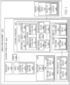
- Fig. 1 schematically illustrates a manufacturing environment 230 in which the ultrasonic cutting operation is performed on the workpiece 202.
- the ultrasonic cutting operation refers to or includes any cutting, trimming, or shaping operation performed on the workpiece 202 using the ultrasonic cutting blade 100.
- Figs. 2 and 3 schematically illustrate examples of the ultrasonic cutting blade 100.
- the ultrasonic cutting blade 100 includes a first end 104, a second end 106, and a curved body 102.
- the curved body 102 extends between the first end 104 and the second end 106.
- the first end 104 and the second end 106 are at least approximately parallel to each other.
- the first end 104 and the second end 106 are non-parallel to each other.
- the first end 104 and the second end 106 are opposite each other and aligned along an axis that is transverse to the longitudinal axis 124.
- the curved body 102 includes a first edge 110.
- the first edge 110 is configured to contact the workpiece 202 for performing the ultrasonic cutting operation (also referred to herein as a cutting operation or cutting) on the workpiece 202.
- the curved body 102 includes a radius of curvature 112.
- the radius of curvature 112 varies between a minimum radius of curvature 114 and a maximum radius of curvature 116.
- a value for the radius of curvature 112 at any location along the curved body 102 varies between a minimum radius value and a maximum radius value.
- the curved body 102 includes a plurality of values for or instances of the radius of curvature 112 and each value or instance is different than at least one other value or instance of the radius of curvature 112 along a curve profile of the curved body 102 and/or of the first edge 110.
- the curved body 102 of the ultrasonic cutting blade 102 has an open curve profile shape, in elevation view.
- the curved body 102 and/or the first edge 110 can be described as having a U-shape or having a parabolic shape.
- the ultrasonic cutting blade 100 can also be referred to as a ring blade.
- the first edge 110 is relatively thin and sharp for performing the cutting.
- the first edge 110 can also be referred to as a cutting edge, a belly, or a blade edge.
- the first edge 110 of the curved body 102 also includes the radius of curvature 112, in which the values or instances of the radius of curvature 112 vary at different points along the curve profile of the first edge 110 between the minimum radius of curvature 114 and the maximum radius of curvature 116.
- radius of curvature refers to the radius of a circular arc that best approximates a curve at a point along a curve profile of a curved body, such as that of the curved body 102 of the first edge 110 (e.g., as shown in Figs. 2 and 3 ).
- the radius of curvature 112 (e.g., a value for the radius of curvature) varies along the curve profile of the curved body 102, or along the first edge 110.
- the radius of curvature 112 at any point along the curved body 102, or along the first edge 110 is different than the radius of curvature 112 at another point, or any other point, along the curved body 102, or along the first edge 110.
- the ultrasonic cutting blade 100 includes a longitudinal axis 124. During the ultrasonic cutting operation, the ultrasonic cutting blade 100 oscillates axially along the longitudinal axis 124. During the ultrasonic cutting operation, the ultrasonic cutting blade 100 is moved in a moving direction, for example, along a cut path 218, and the first edge 110 is aligned with the moving direction.
- the curved body 102 and/or the first edge 110 is axisymmetric about the longitudinal axis 124.
- the ultrasonic cutting blade 100 is axisymmetric about the longitudinal axis 124 (i.e., the longitudinal axis 124 is the axis of symmetry).
- symmetry of the ultrasonic cutting blade 100, the curved body 102, and/or the first edge 110 facilitates a reduction in chatter during the ultrasonic cutting operation.
- the curved body 102 and/or the first edge 110 is not symmetric, for example, is not axisymmetric about the longitudinal axis 124 (e.g., an axis of symmetry).
- the curved body 102 and/or the first edge 110 includes a first arcuate section 118 and a second arcuate section 120.
- the first arcuate section 118 extends from the first end 104 to a vertex 122 of the curved body 102.
- the second arcuate section 120 extends from the vertex 122 to the second end 106.
- the minimum radius of curvature 114 is at the vertex 122.
- the vertex 122 refers to the vertex of the U-shaped or parabolic curve profile of the curved body 102 or to a point of intersection of the curve profile of the curved body 102 and/or the first edge 110 and the axis of symmetry (e.g., the longitudinal axis 124).
- the maximum radius of curvature 116 is proximate at least one of the first end 104 and the second end 106 of the curved body 102. In other examples, the maximum radius of curvature 116 may be located at another point along the curved body 102 and/or the first edge 110.
- the maximum radius of curvature 116 of the first arcuate section 118 and the maximum radius of curvature 116 of the second arcuate section 120 are the same and are located at opposing points on the curved body 102, such as when the curved body 102 is symmetric. In other examples, the maximum radius of curvature 116 of the first arcuate section 118 and the maximum radius of curvature 116 of the second arcuate section 120 are different and/or are located at different points on the curved body 102, such as when the curved body 102 is not symmetric.
- the radius of curvature 112 increases from the minimum radius of curvature 114 to the maximum radius of curvature 116 along the curved body 102 from the vertex 122 to proximate the first end 104. In one or more examples, the radius of curvature 112 increases from the minimum radius of curvature 114 to the maximum radius of curvature 116 along the curved body 102 from the vertex 122 to proximate the second end 106 of the curved body 102.
- the radius of curvature 112 increases from the minimum radius of curvature 114 to the maximum radius of curvature 116 along the curved body 102 from the vertex 122 to proximate the first end 104 and proximate the second end 106, respectively. In other examples, the radius of curvature 112 increases from the minimum radius of curvature 114 to the maximum radius of curvature 116 and then decreases from the maximum radius of curvature 116 toward the minimum radius of curvature 114.
- the radius of curvature 112 increases linearly from the minimum radius of curvature 114 to the maximum radius of curvature 116. In one or more examples, the radius of curvature 112 increases exponentially from the minimum radius of curvature 114 to the maximum radius of curvature 116. The manner of increase of the radius of curvature 112 from the minimum radius of curvature 114 to the maximum radius of curvature 116 may depend on various factors, such as, but not limited to, the type, geometry, and/or purpose of the cut being made in the workpiece 202, the material composition of the workpiece 202, and the like.
- the maximum radius of curvature 116 is at least 2 times greater than the minimum radius of curvature 114. In one or more examples, the maximum radius of curvature 116 is at least 4 times greater than the minimum radius of curvature 114. In one or more examples, the maximum radius of curvature 116 is at least 5 times greater than the minimum radius of curvature 114. In one or more examples, the maximum radius of curvature 116 is at least 7 times greater than the minimum radius of curvature 114. In one or more examples, the maximum radius of curvature 116 is at least 10 times greater than the minimum radius of curvature 114.
- the minimum radius of curvature 114 is approximately 0.25 inch (approximately 6.3 millimeters). In one or more examples, the maximum radius of curvature 116 is up to approximately 1.5 inches (approximately 38.1 millimeters), such as up to approximately 3.5 inches (approximately 88.9 millimeters). However, other minimum and maximum values for the radius of curvature 112 are also contemplated depending on the application of the ultrasonic cutting blade 100.
- the ultrasonic cutting blade 100 includes a dual-shank connector 138 for connection to a blade holder 108.
- the blade holder 108 couples the ultrasonic cutting blade 100 to a source 204 of ultrasonic vibrations 206, such as an ultrasonic cutting tool 208 ( Fig. 4 ).
- the blade holder 108 transfers the ultrasonic vibrations 206 from the source 204 (e.g., the ultrasonic cutting tool 208) to the ultrasonic cutting blade 100.
- the blade holder 108 may also be referred to as a horn.
- the blade holder 108 includes a base 140 and a tang 142.
- the base 140 is coupled to the source 204 of ultrasonic vibrations 206, such as the ultrasonic cutting tool 208 ( Fig. 4 ), by any suitable coupling technique, such as by a threaded connection, a clamp, a chuck, or the like.
- the tang 142 extends from the base 140 and is coupled to the dual-shank connector 138 of the ultrasonic cutting blade 100.
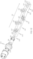
- the tang 142 fits between a space 144 ( Fig. 7 ) within the dual-shank connector 138.
- the ultrasonic cutting blade 100 (e.g., the dual-shank connector 138) includes a first shank 132 and a second shank 134.
- the first shank 132 extends from the curved body 102 at the first end 104.
- the second shank 134 extends from the curved body 102 at the second end 106.
- the first shank 132 and the second shank 134 are opposite each other.
- the first shank 132 and the second shank 134 are at least approximately parallel to each other.
- the first shank 132 and the second shank 134 are non-parallel to each other.
- first shank 132 and the second shank 134 are opposite each other and aligned along an axis that is transverse to the longitudinal axis 124.
- the first shank 132 and the second shank 134 are couplable to the blade holder 108.
- the tang 142 fits within the space 144 ( Fig. 7 ) between the first shank 132 and the second shank 134.
- Each one of the first shank 132, the second shank 134, and the tang 142 includes fastener apertures 146.
- the first shank 132, the second shank 134, and the tang 142 are coupled together by fasteners 148 (e.g., threaded fasteners, such as bolts) that extend through the fastener apertures 146 of the first shank 132, the second shank 134, and the tang 142 (as shown in Figs. 5 and 6 ).
- the dual-shank connector 138 takes the form of a clevis and, as such, the first shank 132 takes the form of a first clevis arm and the second shank 134 takes the form of a second clevis arm.
- the tang 142 is configured to be located between and to be coupled to the first clevis arm and the second clevis arm by one or more of the fasteners 148.
- the ultrasonic vibrations 206 are generated by the ultrasonic cutting tool 208.
- the ultrasonic vibrations 206 are transferred to the blade holder 108.
- the ultrasonic vibrations 206 are transferred from the blade holder 108 to the ultrasonic cutting blade 100.
- the ultrasonic vibrations 206 are transferred through two contact interfaces 136 between blade holder 108 and the ultrasonic cutting blade 100.
- deflection of the ultrasonic cutting blade 100 is also reacted by or through the two contact interfaces 136. Transferring the ultrasonic vibrations 206 and reacting to the deformation through the two contact interfaces 136 reduces chatter during the ultrasonic cutting operation.
- the two contact interfaces 136 includes a first contact interface 150 and a second contact interface 152.
- the first contact interface 150 includes or is formed by intimate, engaging surface-to-surface contact between a first shank surface 154 of the first shank 132 and a first tang surface 158 of the tang 142.
- the second contact interface 152 includes or is formed by intimate, engaging surface-to-surface contact between a second shank surface 156 of the first shank 132 and a second tang surface 160 of the tang 142.
- the contact interfaces 136 provide an increase in contact surface area between the first shank 132, the second shank 134, and the tang 142.
- the increase in the contact surface area optimizes the transmission of the ultrasonic vibrations 206 compared to a single connection, such as traditional ultrasonic blade holders.
- the increase in the contact surface area also reduces deflection compared to a single connection, such as traditional ultrasonic blade holders. Optimization of the transmission of the ultrasonic vibrations 206 and reduction of the deflection of the ultrasonic cutting blade 100 result in a reduction in chatter. It can be appreciated that chatter can result in poor cut quality and/or premature blade breakage.
- the curved body 102 is capable of flexing inward, in a direction at least approximately perpendicular to the longitudinal axis 124, thereby enabling the dual-shank connector 138 to clamp down on the tang 142.
- the clamping force increases surface contact and improves transmission of the ultrasonic vibrations 206 to the ultrasonic cutting blade 100, thereby reducing chatter.
- the contact interfaces 136 include a gel 162 ( Fig. 5 ).
- the gel 162 includes any suitable ultrasound coupling medium or ultrasonic gel.
- the gel further optimizes the transmission of the ultrasonic vibrations 206 and, thereby, further reduces chatter.
- the gel 162 is applied between the first shank surface 154 and the first tang surface 158 and between the second shank surface 156 and the second tang surface 160.
- the curved body 102 includes a second edge 126.
- the second edge 126 is opposite the first edge 110.
- the curved body 102 includes a surface 128 that extends between the first edge 110 and the second edge 126.
- the second edge 126 is relatively thick and dull and may form the thickest and strongest part of the curved body 102.
- the first edge 110 can also be referred to as a spine.
- the second edge 126 of the curved body 102 may also include the radius of curvature 112.
- the second edge 126 is spaced away from the first edge 110 along the longitudinal axis 124.
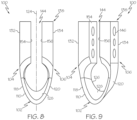
- the second edge 126 is positioned radially inward relative to the first edge 110, in elevation view (e.g., as shown in Fig. 8 ).
- the surface 128 is oriented at oblique angle relative to the longitudinal axis 124.
- the surface 128 is concave in a direction extending between the first edge 110 and the second edge 126.
- the ultrasonic cutting blade 100 such as the surface 128 of the curved body 102, may be referred to as being shoveled or scooped.
- the first edge 110 is configured to make an arcuate cut 212 ( Fig. 11 ) in the workpiece 202 in response to moving the ultrasonic cutting blade 100 along the cut path 218 ( Fig. 12 ).
- the arcuate cut 212 has a cut radius of curvature 214.
- the cut radius of curvature 214 is between (e.g., can vary between) the minimum radius of curvature 114 and the maximum radius of curvature 116 based on a cutting angle 220 ( Fig. 12 ) of the curved body 102 relative to the workpiece 202 or a workpiece surface 216 of the workpiece 202.
- the ultrasonic cutting system 200 includes the ultrasonic cutting blade 100 and the ultrasonic cutting tool 208.
- the ultrasonic cutting system 200 includes the blade holder 108 that couples the ultrasonic cutting blade 100 to the ultrasonic cutting tool 208.
- the ultrasonic cutting tool 208 transmits the ultrasonic vibrations 206 to the ultrasonic cutting blade 100 via the blade holder 108.
- the ultrasonic cutting blade 100 includes the first end 104, the second end 106, and the curved body 102.
- the curved body 102 extends between the first end 104 and the second end 106.
- the first end 104 and the second end 106 are generally aligned with each other across the longitudinal axis 124, such as at least approximately parallel.
- the curved body 102 includes the first edge 110 that is configured to contact the workpiece 202 for performing the cutting operation on the workpiece 202.
- the curved body 102 includes the radius of curvature 112 that varies between the minimum radius of curvature 114 and the maximum radius of curvature 116.
- the ultrasonic cutting tool 208 is an example of the source 204 of the ultrasonic vibrations 206.
- the ultrasonic cutting tool 208 includes any suitable ultrasonic oscillator that is configured or adapted to be driven to vibrate in a direction of the longitudinal axis 124 and, thereby, ultrasonically vibrating the ultrasonic cutting blade 100.
- the ultrasonic cutting system 200 includes at least one of an articulated robot 210 and a gantry 222 that moves the ultrasonic cutting tool 208.
- the ultrasonic cutting tool 208 is mounted on an end of the articulated robot 210.
- the ultrasonic cutting tool 208 is mounted on the gantry 222.
- the articulated robot 210 includes or takes the form of any programmable robot, such as a robotic arm.
- the articulated robot 210 is a six-axis articulated robot that has six degrees of freedom, such that both a location and an orientation of the ultrasonic cutting blade 100 can be controlled freely in three-dimensional space.
- the gantry 222 is an overhead gantry that includes a manipulator to which the ultrasonic cutting tool 208 is coupled.
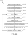
- the present disclosure is directed to a method 1000 for cutting the workpiece 202.
- the method 1000 is implemented or performed using the ultrasonic cutting system 200 that utilizes the ultrasonic cutting blade 100.
- the method 1000 includes a step of (block 1002) mounting or coupling the ultrasonic cutting blade 100 to the source 204 of the ultrasonic vibrations 206, such as to the ultrasonic cutting tool 208.
- ultrasonic cutting blade 100 is coupled to the source 204 via the blade holder 108.
- the method 1000 includes a step of (block 1004) driving the ultrasonic cutting blade 100 via the source 204 of the ultrasonic vibrations 206.
- the ultrasonic vibrations 206 are generated by the source 204 (e.g., the ultrasonic cutting tool 208), are transmitted through the blade holder 108 to the ultrasonic cutting blade 100, and travel through and along the ultrasonic cutting blade 100 such that the ultrasonic cutting blade 100 is ultrasonically vibrated.
- the method 1000 includes a step of (block 1006) positioning the ultrasonic cutting blade 100 at the cutting angle 220 relative to the workpiece surface 216 of the workpiece 202 in order to set an initial orientation of the ultrasonic cutting blade 100 and, more particularly, the orientation of the first edge 110 relative to the workpiece 202.
- the method 1000 includes a step of (block 1008) contacting the workpiece 202 with the first edge 110 of the ultrasonic cutting blade 100. In one or more examples, the method 1000 includes a step of (block 1010) moving the ultrasonic cutting blade 100 along the cut path 218. In one or more examples, the method 1000 includes a step of (block 1012) forming the arcuate cut 212 in the workpiece 202. Generally, the step of (block 1012) forming the arcuate cut 212 in the workpiece 202 includes cutting or trimming away portions of the workpiece 202 using the ultrasonic cutting blade 100.
- the step of (block 1010) moving the ultrasonic cutting blade 100 is performed during the step of (block 1004) driving the ultrasonic cutting blade 100 and with the ultrasonic cutting blade 100 positioned at the cutting angle 220 (e.g., after the step of (block 1006) positioning the ultrasonic cutting blade 100).
- the step of (block 1004) driving, the step of (block 1006) positioning, and the step of (block 1010) moving the ultrasonic cutting blade 100 along the cut path 218 form or result in formation of the arcuate cut 212.
- the method 1000 includes a step of (block 1014) changing or modifying the cutting angle 220 of the ultrasonic cutting blade 100 in order to reposition the orientation of the ultrasonic cutting blade 100 and, more particularly, the orientation of the first edge 110 relative to the workpiece 202.
- the step of (block 1014) changing the cutting angle 220 is performed during the step of (block 1004) driving the ultrasonic cutting blade 100 and the step of (block 1010) moving the ultrasonic cutting blade 100 and during the step of (block 1012) forming the arcuate cut 212.
- the method 1000 includes a step of (block 1016) varying the cut radius of curvature 214 of the arcuate cut 212 between the minimum radius of curvature 114 and the maximum radius of curvature 116 based on the step of (block 1014) changing of the cutting angle 220.
- the step of (block 1004) driving the ultrasonic cutting blade 100, the step of (block 1010) moving the ultrasonic cutting blade 100, and the step of (block 1014) changing the cutting angle 220 of the ultrasonic cutting blade 100 during the step of (block 1012) forming the arcuate cut 212 in the workpiece 202 form or result in variations in the cut radius of curvature 214 of the arcuate cut 212 along the cut path 218.
- Variations in the cut radius of curvature 214 of the actuate cut 212 provide an adaptive, three-dimensional curved surface in the workpiece 202.
- Examples of the method 1000 and the ultrasonic cutting blade 100, disclosed herein, advantageously enable formation of at least one arcuate cut 212 having a desired cut radius of curvature 214 or variations in the cut radius of curvature 214 after a single cutting pass of the ultrasonic cutting blade 100.
- the cut radius of curvature 214 and/or or variations in the cut radius of curvature 214 are controllable between a minimum radius and a maximum radius depending on the cutting angle 220 of the ultrasonic cutting blade 100 and the radius of curvature 112 of the ultrasonic cutting blade 100.
- Fig. 10 illustrates an example of the workpiece 202 before the ultrasonic cutting operation.
- Fig. 11 illustrates an example of the workpiece 202 after the ultrasonic cutting operation in which the workpiece 202 includes the arcuate cut 212 and the arcuate cut 212 has the cut radius of curvature 214 that varies between the minimum radius of curvature 114 and the maximum radius of curvature 116.
- Fig. 12 illustrates an example implementation of the method 1000. More particularly, Fig. 12 illustrates an example of the ultrasonic cutting blade 100 oriented at different instances of the cutting angle 220 at different locations on the workpiece 202 as the ultrasonic cutting blade 100 is moved along the cut path 218.
- Figs. 12 illustrates an example of the ultrasonic cutting blade 100 oriented at different instances of the cutting angle 220 at different locations on the workpiece 202 as the ultrasonic cutting blade 100 is moved along the cut path 218.
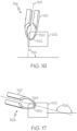
- FIG. 13-19 illustrate examples of the ultrasonic cutting blade 100 at the different locations depicted in Fig. 12 and at the different instances of the cutting angle 220 associated with different portions of the arcuate cut 212 having the cut radius of curvature 214 corresponding to the cutting angle 220.
- Fig. 13 illustrates an example of the ultrasonic cutting system 200, including the ultrasonic cutting tool 208, the blade holder 108, and the ultrasonic cutting blade 100, in a position, such as a first position 300 (also shown in Fig. 12 ), for example, when first contacting the workpiece 202 (e.g., block 1008 of the method 1000).
- the ultrasonic cutting blade 100 In the cutting position, the ultrasonic cutting blade 100 is oriented at the cutting angle 220.
- the ultrasonic cutting blade 100 can be oriented at a different instance of the cutting angle 220 to form the arcuate cut 212 with an adaptive radius.
- Fig. 14 illustrates an example of the ultrasonic cutting blade 100 in the first position 300 and at a first cutting angle 302 (also shown in Fig. 12 ), while moving the ultrasonic cutting blade 100 along the cut path 218 (e.g., block 1010 of the method 1000) and forming a first arcuate cut 304, for example, a first portion of the arcuate cut 212 (e.g., block 1012 of the method 1000).
- the first arcuate cut 304 has a first cut radius of curvature 306 based on the first cutting angle 302 of the ultrasonic cutting blade 100.
- Fig. 15 illustrates an example of the ultrasonic cutting blade 100 in a second position 308 and at a second cutting angle 310 (also shown in Fig. 12 ), while moving the ultrasonic cutting blade 100 along the cut path 218 (e.g., block 1010 of the method 1000) and forming a second arcuate cut 312, for example, a second portion of the arcuate cut 212 (e.g., block 1012 of the method 1000).
- the second arcuate cut 312 has a second cut radius of curvature 314 based on the second cutting angle 310 of the ultrasonic cutting blade 100.
- Fig. 16 illustrates an example of the ultrasonic cutting blade 100 in a third position 316 and at a third cutting angle 318 (also shown in Fig. 12 ), while moving the ultrasonic cutting blade 100 along the cut path 218 (e.g., block 1010 of the method 1000) and forming a third arcuate cut 320, for example, a third portion of the arcuate cut 212 (e.g., block 1012 of the method 1000).
- the third arcuate cut 320 has a third cut radius of curvature 322 based on the third cutting angle 318 of the ultrasonic cutting blade 100.
- Fig. 17 illustrates an example of the ultrasonic cutting blade 100 in a fourth position 324 and at a fourth cutting angle 326 (also shown in Fig. 12 ), while moving the ultrasonic cutting blade 100 along the cut path 218 (e.g., block 1010 of the method 1000) and forming a fourth arcuate cut 328, for example, a fourth portion of the arcuate cut 212 (e.g., block 1012 of the method 1000).
- the fourth arcuate cut 328 has a fourth cut radius of curvature 330 based on the fourth cutting angle 326 of the ultrasonic cutting blade 100.
- Fig. 18 illustrates an example of the ultrasonic cutting blade 100 in a fifth position 332 and at a fifth cutting angle 334 (also shown in Fig. 12 ), while moving the ultrasonic cutting blade 100 along the cut path 218 (e.g., block 1010 of the method 1000) and forming a fifth arcuate cut 336, for example, a fifth portion of the arcuate cut 212 (e.g., block 1012 of the method 1000).
- the fifth arcuate cut 336 has a fifth cut radius of curvature 338 based on the fifth cutting angle 334 of the ultrasonic cutting blade 100.
- Fig. 19 illustrates an example of the ultrasonic cutting blade 100 in a sixth position 340 and at a sixth cutting angle 342 (also shown in Fig. 12 ), while moving the ultrasonic cutting blade 100 along the cut path 218 (e.g., block 1010 of the method 1000) and forming a sixth arcuate cut 344, for example, a sixth portion of the arcuate cut 212 (e.g., block 1012 of the method 1000).
- the sixth arcuate cut 344 has a sixth cut radius of curvature 346 based on the sixth cutting angle 342 of the ultrasonic cutting blade 100.
- any number of arcuate cuts e.g., any number of portions of the arcuate cut 212
- each one of the arcuate cuts e.g., each one of the portions of the arcuate cut 212
- the method 1000 includes a step of (block 1018) repositioning the ultrasonic cutting blade 100 relative to the workpiece 202 and, more particularly, relative to a portion of the arcuate cut 212 that was previously formed in the workpiece 202 in order to set a subsequent orientation of the ultrasonic cutting blade 100 and, more particularly, a subsequent orientation of the first edge 110 relative to the workpiece 202.
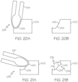
- a portion of the method 1000 can be repeated to form a subsequent instance of the arcuate cut 212 over top or at least partially intersecting the first instance of the arcuate cut 212 to form a cut 232 that has a complex contour 234, such as more than one arcuate section (e.g., as shown in Figs. 20B and 21B ).
- the ultrasonic cutting blade 100 can be repositioned at any point or location along the arcuate cut 212.
- the ultrasonic cutting blade 100 is oriented at an instance of the cutting angle 220 that is different than the instance of the cutting angle 220 used during the step of (block 1012) forming the arcuate cut 212.
- the actuate cut 212 has a first instance of the cut radius of curvature 214 made during a first pass of the ultrasonic cutting blade 100 at a first instance of the cutting angle 220 and at one or more locations or along one or more portions of the workpiece 202, the actuate cut 212 has a second instance of the cut radius of curvature 214 made during a second pass of the ultrasonic cutting blade 100 at a second instance of the cutting angle 220.
- Figs. 20A and 21A illustrate an example implementation of a portion of the method 1000. More particularly, Figs. 20A and 21A illustrates an example of the ultrasonic cutting blade 100 oriented at different instances of the cutting angle 220 at the same location on the workpiece 202 as the ultrasonic cutting blade 100 makes subsequent passes over the same location.
- Fig. 20A illustrates an example of the ultrasonic cutting blade 100 at a location 236 on the workpiece 202 and oriented at a first instance of the cutting angle 220 to form a first arcuate portion 238 of the cut 232 at the location 236.
- Fig. 20B illustrates an example of the workpiece 202 having the first arcuate portion 238 of the cut 232 formed by the ultrasonic cutting blade 100 at the first instance of the cutting angle 220 shown in Fig. 20A .
- the first arcuate portion 238 of the cut 232 has first cut-portion radius of curvature 242 based on the first instance of the cutting angle 220 of the ultrasonic cutting blade 100.
- Fig. 21A illustrates an example of the ultrasonic cutting blade 100 at the location 236 on the workpiece 202 and at a second instance of the cutting angle 220 to form a second arcuate portion 240 of the cut 232 at the location 236.
- Fig. 21B illustrates an example of the workpiece 202 having the second arcuate portion 240 of the cut 232 formed by the ultrasonic cutting blade 100 at the second instance of the cutting angle 220 shown in Fig. 21A .
- the second arcuate portion 240 of the cut 232 has second cut-portion radius of curvature 244 based on the second instance of the cutting angle 220 of the ultrasonic cutting blade 100.
- the second arcuate portion 240 of the cut 232 is formed over top of or at least partially intersects the first arcuate portion 238 of the cut 232 such that the cut 232 includes the complex contour 234.
- any number of cuts or any number of portions of an elongated cut can include the complex contour 234 formed by any number of arcuate portions.
- the present disclosure is also directed to the workpiece. 202.
- the workpiece 202 includes the arcuate cut 212 (e.g., as shown in Fig. 11 ), which is formed according to the method 1000 and/or using the ultrasonic cutting system 200.
- the workpiece 202 includes the cut 232 having the complex contour 234 (e.g., as shown in Fig. 21B ), which is formed according to the method 1000 and/or using the ultrasonic cutting system 200.
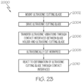
- the present disclosure is directed to a method 2000 for reducing chatter during an ultrasonic cutting operation, such as during the method 1000.
- the method 2000 is implemented or performed using the ultrasonic cutting system 200 that utilizes the ultrasonic cutting blade 100.
- the method 2000 includes a step of (block 2002) mounting or coupling the ultrasonic cutting blade 100 to the source 204 of the ultrasonic vibrations 206, such as to the ultrasonic cutting tool 208.
- ultrasonic cutting blade 100 is coupled to the source 204 via the blade holder 108.
- the method 2000 includes a step of (block 2004) driving the ultrasonic cutting blade 100 via the source 204 of the ultrasonic vibrations 206.
- the ultrasonic vibrations 206 are generated by the source 204 (e.g., the ultrasonic cutting tool 208), are transmitted through the blade holder 108 to the ultrasonic cutting blade 100, and travel through and along the ultrasonic cutting blade 100 such that the ultrasonic cutting blade 100 is ultrasonically vibrated.
- the method 2000 includes a step of (block 2006) transferring the ultrasonic vibrations 206 through the two contact interfaces 136 between the ultrasonic cutting blade 100 and the blade holder 108 that connects the ultrasonic cutting blade 100 to the source 204 of the ultrasonic vibrations 206 (e.g., the ultrasonic cutting tool 208).
- the method 2000 includes a step of (block 2008) ultrasonically cutting the workpiece 202 using the ultrasonic cutting blade 100. In one or more examples, the method 2000 includes a step of (block 2010) reacting to deflection of the ultrasonic cutting blade 100 through the two contact interfaces 136.
- examples of the ultrasonic cutting blade 100, the ultrasonic cutting system 200, the method 1000, the method 2000, and the workpiece 202 having the arcuate cut 212 described herein may be related to, or used in the context of, an aircraft manufacturing and service method 1100, as shown in the flow diagram of Fig. 24 and an aircraft 1200, as schematically illustrated in Fig. 25 .
- the aircraft 1200 and/or the aircraft production and service method 1100 may include the workpiece 202 that is cut, trimmed, or shaped using the ultrasonic cutting blade 100, the ultrasonic cutting system 200 and/or according to the method 1000 and the method 2000.
- the workpiece 202 is a noodle or radius filler used during fabrication of a composite blade stringer of the aircraft 1200.
- the noodle is shaped to fill a cavity of the stringer.
- the ultrasonic cutting blade 100 and the method 1000 allows for creating unique, custom (e.g., wave-like) cuts on noodles to match ramping features of stringers.
- the curved body 102, having a ring shape design, of the ultrasonic cutting blade 100 allows for uniform wave propagation from a single vibration source.
- the ultrasonic cutting blade 100 enables a higher wing panel pull-up allowance given that gaps and wrinkles are reduced and, thus, provides better structural integrity. Overall, higher gap pull-up reduces voids between wing-to-spar and rib structures and, thus, eliminate shimming work downstream.
- the aircraft 1200 includes an airframe 1202 having an interior 1206.
- the aircraft 1200 includes a plurality of onboard systems 1204 (e.g., high-level systems).
- Examples of the onboard systems 1204 of the aircraft 1200 include propulsion systems 1208, hydraulic systems 1212, electrical systems 1210, and environmental systems 1214.
- the onboard systems 1204 also includes one or more control systems coupled to an airframe 1202 of the aircraft 1200, such as for example, flaps, spoilers, ailerons, slats, rudders, elevators, and trim tabs.
- the onboard systems 1204 also includes one or more other systems, such as, but not limited to, communications systems, avionics systems, software distribution systems, network communications systems, passenger information/entertainment systems, guidance systems, radar systems, weapons systems, and the like.
- the aircraft 1200 may include various other structures made using the workpiece 202 that is cut, trimmed, or shaped using the ultrasonic cutting blade 100, the ultrasonic cutting system 200 and/or according to the method 1000 and the method 2000.
- the manufacturing and service method 1100 includes specification and design of the aircraft 1200 (block 1102) and material procurement (block 1104).
- component and subassembly manufacturing (block 1106) and system integration (block 1108) of the aircraft 1200 take place. Thereafter, the aircraft 1200 goes through certification and delivery (block 1110) to be placed in service (block 1112).
- Routine maintenance and service (block 1114) includes modification, reconfiguration, refurbishment, etc. of one or more systems of the aircraft 1200.
- a system integrator may include, without limitation, any number of spacecraft manufacturers and major-system subcontractors; a third party may include, without limitation, any number of vendors, subcontractors, and suppliers; and an operator may be an airline, leasing company, military entity, service organization, and so on.
- Examples of the ultrasonic cutting blade 100, the ultrasonic cutting system 200, the method 1000, the method 2000, and the workpiece 202 having the arcuate cut 212 shown and described herein, may be employed during any one or more of the stages of the manufacturing and service method 1100 shown in the flow diagram illustrated by Fig. 22 .
- making the workpiece 202 that is cut, trimmed, or shaped using the ultrasonic cutting blade 100 or the ultrasonic cutting system 200 and/or according to the method 1000 and the method 2000 may form a portion of component and subassembly manufacturing (block 1106) and/or system integration (block 1108).
- the workpiece 202 that is cut, trimmed, or shaped using the ultrasonic cutting blade 100 or the ultrasonic cutting system 200 and/or according to the method 1000 and the method 2000 may be implemented in a manner similar to components or subassemblies prepared while the aircraft 1200 is in service (block 1112). Also, the workpiece 202 that is cut, trimmed, or shaped using the ultrasonic cutting blade 100 or the ultrasonic cutting system 200 and/or according to the method 1000 and the method 2000 may be utilized during system integration (block 1108) and certification and delivery (block 1110).
- the workpiece 202 that is cut, trimmed, or shaped using the ultrasonic cutting blade 100 or the ultrasonic cutting system 200 and/or according to the method 1000 and the method 2000 may be utilized, for example and without limitation, while the aircraft 1200 is in service (block 1112) and during maintenance and service (block 1114).
- example means that one or more feature, structure, element, component, characteristic, and/or operational step described in connection with the example is included in at least one aspect, embodiment, and/or implementation of the subject matter according to the present disclosure.
- the phrases “an example,” “another example,” “one or more examples,” and similar language throughout the present disclosure may, but do not necessarily, refer to the same example.
- the subject matter characterizing any one example may, but does not necessarily, include the subject matter characterizing any other example.
- subject matter characterizing any one example may be, but is not necessarily, combined with the subject matter characterizing any other example.
- a system, apparatus, device, structure, article, element, component, or hardware "configured to” perform a specified function is indeed capable of performing the specified function without any alteration, rather than merely having potential to perform the specified function after further modification.
- the system, apparatus, device, structure, article, element, component, or hardware "configured to” perform a specified function is specifically selected, created, implemented, utilized, programmed, and/or designed for the purpose of performing the specified function.
- "configured to” denotes existing characteristics of a system, apparatus, structure, article, element, component, or hardware that enable the system, apparatus, structure, article, element, component, or hardware to perform the specified function without further modification.
- a system, apparatus, device, structure, article, element, component, or hardware described as being “configured to” perform a particular function may additionally or alternatively be described as being “adapted to” and/or as being “operative to” perform that function.
- first,” “second,” “third,” etc. are used herein merely as labels, and are not intended to impose ordinal, positional, or hierarchical requirements on the items to which these terms refer. Moreover, reference to, e.g., a “second” item does not require or preclude the existence of, e.g., a "first” or lower-numbered item, and/or, e.g., a "third” or higher-numbered item.
- the phrase "at least one of”, when used with a list of items, means different combinations of one or more of the listed items may be used and only one of each item in the list may be needed.
- “at least one of item A, item B, and item C” may include, without limitation, item A or item A and item B. This example also may include item A, item B, and item C, or item B and item C.
- "at least one of' may be, for example, without limitation, two of item A, one of item B, and ten of item C; four of item B and seven of item C; and other suitable combinations.
- the term “and/or” and the "j" symbol includes any and all combinations of one or more of the associated listed items.
- Coupled refers to two or more elements that are joined, linked, fastened, attached, connected, put in communication, or otherwise associated (e.g., mechanically, electrically, fluidly, optically, electromagnetically) with one another.
- the elements may be associated directly or indirectly.
- element A may be directly associated with element B.
- element A may be indirectly associated with element B, for example, via another element C. It will be understood that not all associations among the various disclosed elements are necessarily represented. Accordingly, couplings other than those depicted in the figures may also exist.
- the term “approximately” refers to or represent a condition that is close to, but not exactly, the stated condition that still performs the desired function or achieves the desired result.
- the term “approximately” refers to a condition that is within an acceptable predetermined tolerance or accuracy, such as to a condition that is within 10% of the stated condition.
- the term “approximately” does not exclude a condition that is exactly the stated condition.
- the term “substantially” refers to a condition that is essentially the stated condition that performs the desired function or achieves the desired result.
- Figs. 1-21 and 25 may represent functional elements, features, or components thereof and do not necessarily imply any particular structure. Accordingly, modifications, additions and/or omissions may be made to the illustrated structure. Additionally, those skilled in the art will appreciate that not all elements, features, and/or components described and illustrated in Figs. 1-21 and 25 , referred to above, need be included in every example and not all elements, features, and/or components described herein are necessarily depicted in each illustrative example. Accordingly, some of the elements, features, and/or components described and illustrated in Figs. 1-21 and 25 may be combined in various ways without the need to include other features described and illustrated in Figs.
- elements, features, and/or components that serve a similar, or at least substantially similar, purpose are labeled with like numbers in each of Figs. 1-21 and 25 , and such elements, features, and/or components may not be discussed in detail herein with reference to each of Figs. 1-21 and 25 .
- all elements, features, and/or components may not be labeled in each of Figs. 1-21 and 25 , but reference numerals associated therewith may be utilized herein for consistency.
- Figs. 22-24 referred to above, the blocks may represent operations, steps, and/or portions thereof and lines connecting the various blocks do not imply any particular order or dependency of the operations or portions thereof. It will be understood that not all dependencies among the various disclosed operations are necessarily represented. Figs. 22-24 and the accompanying disclosure describing the operations of the disclosed methods set forth herein should not be interpreted as necessarily determining a sequence in which the operations are to be performed. Rather, although one illustrative order is indicated, it is to be understood that the sequence of the operations may be modified when appropriate. Accordingly, modifications, additions and/or omissions may be made to the operations illustrated and certain operations may be performed in a different order or simultaneously. Additionally, those skilled in the art will appreciate that not all operations described need be performed.
- references throughout the present specification to features, advantages, or similar language used herein do not imply that all of the features and advantages that may be realized with the examples disclosed herein should be, or are in, any single example. Rather, language referring to the features and advantages is understood to mean that a specific feature, advantage, or characteristic described in connection with an example is included in at least one example. Thus, discussion of features, advantages, and similar language used throughout the present disclosure may, but do not necessarily, refer to the same example.
Landscapes
- Engineering & Computer Science (AREA)
- Mechanical Engineering (AREA)
- Life Sciences & Earth Sciences (AREA)
- Forests & Forestry (AREA)
- Physics & Mathematics (AREA)
- Manufacturing & Machinery (AREA)
- Human Computer Interaction (AREA)
- General Physics & Mathematics (AREA)
- Automation & Control Theory (AREA)
- Robotics (AREA)
- Turning (AREA)
- Polishing Bodies And Polishing Tools (AREA)
- Milling, Broaching, Filing, Reaming, And Others (AREA)
- Cutting Tools, Boring Holders, And Turrets (AREA)
- Grinding And Polishing Of Tertiary Curved Surfaces And Surfaces With Complex Shapes (AREA)
Abstract
Description
- The present disclosure relates generally to ultrasonic cutting and, more particularly, to ultrasonic cutting blades and systems and methods for cutting workpieces using the ultrasonic cutting blades.
- In many manufacturing operations, a material workpiece is shaped for a particular application. For example, a workpiece used to fill a gap must be suitably shaped for that gap. Often, the workpiece is cut or trimmed to achieve a desired shape. Typically, an edge tool, an ultrasonic cutter, a water jet, or the like is used for the cutting. Use of an ultrasonic cutter has advantages. However, it can be challenging to trim, cut, or otherwise shape a three-dimensional curved surface in the workpiece using conventional cutting techniques. Accordingly, those skilled in the art continue with research and development efforts in the field of ultrasonic cutting.
- Disclosed are examples of an ultrasonic cutting blade, an ultrasonic cutting system, a method for cutting a workpiece, and a method for reducing chatter during an ultrasonic cutting operation. The following is a non-exhaustive list of examples, which may or may not be claimed, of the subject matter according to the present disclosure.
- In an example, the disclosed ultrasonic cutting blade includes a first end, a second end, and a curved body. The curved body extends between the first end and the second end. The curved body includes a first edge that is configured to contact a workpiece for performing a cutting operation on the workpiece. The curved body includes a radius of curvature that varies between a minimum radius of curvature and a maximum radius of curvature.
- Optionally, the curved body is axisymmetric.
- Optionally, the curved body comprises a first arcuate section that extends from the first end to a vertex of the curved body; and a second arcuate section that extends from the vertex to the second end; the minimum radius of curvature is at the vertex; and the maximum radius of curvature is proximate at least one of the first end and the second end.
- Optionally, the radius of curvature increases linearly from the minimum radius of curvature to the maximum radius of curvature.
- Optionally, the radius of curvature increases exponentially from the minimum radius of curvature to the maximum radius of curvature.
- Optionally, the ultrasonic cutting blade further comprises a longitudinal axis; a second edge that is opposite the first edge; and a surface that extends between the first edge and the second edge, wherein: the second edge is spaced away from the first edge along the longitudinal axis; and the surface is oriented at oblique angle relative to the longitudinal axis. Preferably, the surface is concave.
- Optionally, the maximum radius of curvature is at least 2 times greater than the minimum radius of curvature.
- Optionally, the maximum radius of curvature is at least 4 times greater than the minimum radius of curvature.
- Optionally, the maximum radius of curvature is at least 5 times greater than the minimum radius of curvature.
- Optionally, the maximum radius of curvature is at least 7 times greater than the minimum radius of curvature.
- Optionally, the maximum radius of curvature is at least 10 times greater than the minimum radius of curvature.
- Optionally, the minimum radius of curvature is approximately 6.3 mm (approximately 0.25 inch); and the maximum radius of curvature is up to approximately 38.1 mm (approximately 1.5 inches).
- Optionally, the first edge is configured to make an arcuate cut in the workpiece) in response to moving the ultrasonic cutting blade along a cut path; the arcuate cut has a cut radius of curvature; and the cut radius of curvature is between the minimum radius of curvature and the maximum radius of curvature based on a cutting angle of the curved body relative to a workpiece surface of the workpiece.
- Optionally, the ultrasonic cutting blade further comprises a first shank extending from the first end of the curved body; and a second shank extending from the second end of the curved body, wherein the first shank and the second shank are couplable to a blade holder that couples the ultrasonic cutting blade to a source of ultrasonic vibrations.
- In an example, the disclosed ultrasonic cutting system includes an ultrasonic cutting blade and an ultrasonic cutting tool that transmits ultrasonic vibrations to the ultrasonic cutting blade. The ultrasonic cutting blade includes a first end, a second end, and a curved body. The curved body extends between the first end and the second end. The curved body includes a first edge that is configured to contact a workpiece for performing a cutting operation on the workpiece. The curved body includes a radius of curvature that varies between a minimum radius of curvature and a maximum radius of curvature. Preferably, the ultrasonic cutting blade is an ultrasonic cutting blade according to the above.
- Optionally, the ultrasonic cutting system further comprises a blade holder that couples the ultrasonic cutting blade to the ultrasonic cutting tool. Preferably, the ultrasonic cutting blade further comprises: a first tang.k extending from the first end of the curved body, and a second shank extending from the second end of the curved body; further wherein the blade holder comprises a tang; and the first shank and the second shank are coupled to the tang.
- Optionally, ultrasonic cutting system further comprises at least one of an articulated robot and a gantry that moves the ultrasonic cutting tool.
- Optionally, the ultrasonic cutting system further comprises any one of the above optional features of the ultrasonic cutting blade.
- In an example, the disclosed method for cutting includes steps of: (1) positioning an ultrasonic cutting blade at a cutting angle relative to a workpiece surface of the workpiece; (2) moving the ultrasonic cutting blade along cut path to form an arcuate cut; (3) during the moving, changing the cutting angle of the ultrasonic cutting blade; and (4) varying a cut radius of curvature of the arcuate cut between a minimum radius of curvature and a maximum radius of curvature based on the changing of the cutting angle.
- In an example, a workpiece is provided that comprises an arcuate cut formed according to the above method.
- In an example, the disclosed method for reducing chatter includes steps of: (1) transferring ultrasonic vibrations through two contact interfaces between an ultrasonic cutting blade and a blade holder that connects the ultrasonic cutting blade to a source of the ultrasonic vibrations; and (2) reacting to deflection of the ultrasonic cutting blade through the two contact interfaces.
- Other examples of the ultrasonic cutting blade, the ultrasonic cutting system, the method for cutting, and the method for reducing chatter disclosed herein will become apparent from the following detailed description, the accompanying drawings, and the appended claims.
-
-
Fig. 1 is a schematic block diagram of an example of a manufacturing environment; -
Fig. 2 is schematic, front elevation view of an example of an ultrasonic cutting blade ofFig. 1 ; -
Fig. 3 is schematic, front elevation view of an example of the ultrasonic cutting blade ofFig. 1 ; -
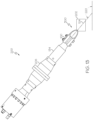
Fig. 4 is schematic, perspective view of an example of the ultrasonic cutting system ofFig. 1 ; -
Fig. 5 is schematic, front elevation view of an example of a portion of the ultrasonic cutting system ofFig. 1 ; -
Fig. 6 is schematic, front perspective view of an example of the portion of the ultrasonic cutting system ofFig. 4 ; -
Fig. 7 is schematic, exploded, perspective view of an example of the portion of the ultrasonic cutting system ofFig. 4 ; -
Fig. 8 is schematic, elevation view of an example of the ultrasonic cutting blade ofFig. 1 ; -
Fig. 9 is schematic, perspective view of an example of the ultrasonic cutting blade ofFig. 7 ; -
Fig. 10 is a schematic, perspective view of an example of a workpiece ofFig. 1 ; -
Fig. 11 is a schematic, perspective view of an example of the workpiece ofFig. 9 having an arcuate cut made using the ultrasonic cutting system ofFig. 1 ; -
Fig. 12 is a schematic, perspective view of an example of the workpiece ofFig. 9 being cut by the ultrasonic cutting system ofFig. 1 ; -
Figs. 12 is a schematic, end view of an example of the ultrasonic cutting system ofFig. 12 ; -
Fig. 13 is a schematic, end view of an example of the ultrasonic cutting system ofFig. 12 at an initial cutting location and position relative to a workpiece; -
Figs. 14-19 are schematic, end views of examples of the ultrasonic cutting blade ofFig. 12 in various cutting positions and at various cutting locations relative to the workpiece; -
Fig. 20A is a schematic, end view of an example of the ultrasonic cutting blade at a cutting location and in a cutting position relative to the workpiece; -
Fig. 20B is a schematic, end view of an example of the workpiece ofFig. 20A after being cut by the ultrasonic cutting blade; -
Fig. 21A is a schematic, end view of an example of the ultrasonic cutting blade at the cutting location ofFig. 20A and in another cutting position relative to the workpiece; -
Fig. 21B is a schematic, end view of an example of the workpiece ofFig. 21A after being cut by the ultrasonic cutting blade; -
Fig. 22 is a flow diagram of an example of a method for cutting a workpiece; -
Fig. 23 is a flow diagram of an example of a method for reducing chatter during an ultrasonic cutting operation; -
Fig. 24 is a flow diagram of an example of an aircraft manufacturing and service method; and -
Fig. 25 is a schematic block diagram of an example of an aircraft. - Referring generally to
Figs. 1-21 , by way of examples, the present disclosure is directed to anultrasonic cutting blade 100 and to anultrasonic cutting system 200, which includes or otherwise utilizes theultrasonic cutting blade 100. As will be described in more detail herein, theultrasonic cutting blade 100 provides a varying cutting radius to cut aworkpiece 202 and, thereby, form a three-dimensional curved surface or a cut with a varying cut radius. During an ultrasonic cutting operation, theultrasonic cutting blade 100 is oriented (e.g., tilted) to change the radius of the cut and, thereby, facilitates cuts of an adaptive or changing radius of curvature along a cut path. Additionally, theultrasonic cutting blade 100 facilitates a reduction in chatter during the ultrasonic cutting operation. - Generally, the
workpiece 202 refers to or includes any object, article, component, part, etc. that is being cut, trimmed, shaped, or otherwise worked on by theultrasonic cutting blade 100. Theworkpiece 202 can have any one of various sizes, shapes, and/or geometries. Theworkpiece 202 can be made of any one or more of various materials including, but not limited to: composite materials, such as a stack of uncured ("green") composite plies, a fiber-reinforced composite, a resin infused composite, and the like; foam materials; soft metallic materials, such as a stack of aluminum sheets; a laminate of metallic and composite sheets; and the like. In one or more examples, theworkpiece 202 having an arcuate cut with an adaptive cut radius can be used as a radius filler, also referred to as a noodle, to effectively fill a noodle cavity of a composite blade stringer, thereby increasing gap pull up allowance and avoiding the use of step cuts to form the contoured or curved shape of the noodle. -
Fig. 1 schematically illustrates amanufacturing environment 230 in which the ultrasonic cutting operation is performed on theworkpiece 202. Generally, the ultrasonic cutting operation refers to or includes any cutting, trimming, or shaping operation performed on theworkpiece 202 using theultrasonic cutting blade 100.Figs. 2 and3 schematically illustrate examples of theultrasonic cutting blade 100. - Referring to
Figs. 1-3 , in one or more examples, theultrasonic cutting blade 100 includes afirst end 104, asecond end 106, and acurved body 102. Thecurved body 102 extends between thefirst end 104 and thesecond end 106. In one or more examples, thefirst end 104 and thesecond end 106 are at least approximately parallel to each other. In other examples, thefirst end 104 and thesecond end 106 are non-parallel to each other. In one or more examples, thefirst end 104 and thesecond end 106 are opposite each other and aligned along an axis that is transverse to thelongitudinal axis 124. Thecurved body 102 includes afirst edge 110. Thefirst edge 110 is configured to contact theworkpiece 202 for performing the ultrasonic cutting operation (also referred to herein as a cutting operation or cutting) on theworkpiece 202. Thecurved body 102 includes a radius ofcurvature 112. The radius ofcurvature 112 varies between a minimum radius ofcurvature 114 and a maximum radius ofcurvature 116. - As an example, a value for the radius of
curvature 112 at any location along thecurved body 102 varies between a minimum radius value and a maximum radius value. For example, thecurved body 102 includes a plurality of values for or instances of the radius ofcurvature 112 and each value or instance is different than at least one other value or instance of the radius ofcurvature 112 along a curve profile of thecurved body 102 and/or of thefirst edge 110. - As illustrated in
Figs. 2 and3 , thecurved body 102 of theultrasonic cutting blade 102 has an open curve profile shape, in elevation view. As such, thecurved body 102 and/or thefirst edge 110 can be described as having a U-shape or having a parabolic shape. Theultrasonic cutting blade 100 can also be referred to as a ring blade. - In one or more examples, the
first edge 110 is relatively thin and sharp for performing the cutting. As such, thefirst edge 110 can also be referred to as a cutting edge, a belly, or a blade edge. Thefirst edge 110 of thecurved body 102 also includes the radius ofcurvature 112, in which the values or instances of the radius ofcurvature 112 vary at different points along the curve profile of thefirst edge 110 between the minimum radius ofcurvature 114 and the maximum radius ofcurvature 116. - Generally, radius of curvature refers to the radius of a circular arc that best approximates a curve at a point along a curve profile of a curved body, such as that of the
curved body 102 of the first edge 110 (e.g., as shown inFigs. 2 and3 ). The radius of curvature 112 (e.g., a value for the radius of curvature) varies along the curve profile of thecurved body 102, or along thefirst edge 110. As an example, the radius ofcurvature 112 at any point along thecurved body 102, or along thefirst edge 110, is different than the radius ofcurvature 112 at another point, or any other point, along thecurved body 102, or along thefirst edge 110. - Referring to
Figs. 1-3 , in one or more examples, theultrasonic cutting blade 100 includes alongitudinal axis 124. During the ultrasonic cutting operation, theultrasonic cutting blade 100 oscillates axially along thelongitudinal axis 124. During the ultrasonic cutting operation, theultrasonic cutting blade 100 is moved in a moving direction, for example, along acut path 218, and thefirst edge 110 is aligned with the moving direction. - Referring to
Figs. 1-3 , in one or more examples, thecurved body 102 and/or thefirst edge 110 is axisymmetric about thelongitudinal axis 124. In one or more examples, theultrasonic cutting blade 100 is axisymmetric about the longitudinal axis 124 (i.e., thelongitudinal axis 124 is the axis of symmetry). In one or more examples, symmetry of theultrasonic cutting blade 100, thecurved body 102, and/or thefirst edge 110 facilitates a reduction in chatter during the ultrasonic cutting operation. In other examples, thecurved body 102 and/or thefirst edge 110 is not symmetric, for example, is not axisymmetric about the longitudinal axis 124 (e.g., an axis of symmetry). - Referring to
Figs. 1-3 , in one or more examples, thecurved body 102 and/or thefirst edge 110 includes a firstarcuate section 118 and a secondarcuate section 120. The firstarcuate section 118 extends from thefirst end 104 to avertex 122 of thecurved body 102. The secondarcuate section 120 extends from thevertex 122 to thesecond end 106. The minimum radius ofcurvature 114 is at thevertex 122. Thevertex 122 refers to the vertex of the U-shaped or parabolic curve profile of thecurved body 102 or to a point of intersection of the curve profile of thecurved body 102 and/or thefirst edge 110 and the axis of symmetry (e.g., the longitudinal axis 124). In one or more examples, the maximum radius ofcurvature 116 is proximate at least one of thefirst end 104 and thesecond end 106 of thecurved body 102. In other examples, the maximum radius ofcurvature 116 may be located at another point along thecurved body 102 and/or thefirst edge 110. - In one or more examples, the maximum radius of
curvature 116 of the firstarcuate section 118 and the maximum radius ofcurvature 116 of the secondarcuate section 120 are the same and are located at opposing points on thecurved body 102, such as when thecurved body 102 is symmetric. In other examples, the maximum radius ofcurvature 116 of the firstarcuate section 118 and the maximum radius ofcurvature 116 of the secondarcuate section 120 are different and/or are located at different points on thecurved body 102, such as when thecurved body 102 is not symmetric. - Referring to
Figs. 1-3 , in one or more examples, the radius ofcurvature 112 increases from the minimum radius ofcurvature 114 to the maximum radius ofcurvature 116 along thecurved body 102 from thevertex 122 to proximate thefirst end 104. In one or more examples, the radius ofcurvature 112 increases from the minimum radius ofcurvature 114 to the maximum radius ofcurvature 116 along thecurved body 102 from thevertex 122 to proximate thesecond end 106 of thecurved body 102. In one or more examples, the radius ofcurvature 112 increases from the minimum radius ofcurvature 114 to the maximum radius ofcurvature 116 along thecurved body 102 from thevertex 122 to proximate thefirst end 104 and proximate thesecond end 106, respectively. In other examples, the radius ofcurvature 112 increases from the minimum radius ofcurvature 114 to the maximum radius ofcurvature 116 and then decreases from the maximum radius ofcurvature 116 toward the minimum radius ofcurvature 114. - In one or more examples, the radius of
curvature 112 increases linearly from the minimum radius ofcurvature 114 to the maximum radius ofcurvature 116. In one or more examples, the radius ofcurvature 112 increases exponentially from the minimum radius ofcurvature 114 to the maximum radius ofcurvature 116. The manner of increase of the radius ofcurvature 112 from the minimum radius ofcurvature 114 to the maximum radius ofcurvature 116 may depend on various factors, such as, but not limited to, the type, geometry, and/or purpose of the cut being made in theworkpiece 202, the material composition of theworkpiece 202, and the like. - In one or more examples, the maximum radius of
curvature 116 is at least 2 times greater than the minimum radius ofcurvature 114. In one or more examples, the maximum radius ofcurvature 116 is at least 4 times greater than the minimum radius ofcurvature 114. In one or more examples, the maximum radius ofcurvature 116 is at least 5 times greater than the minimum radius ofcurvature 114. In one or more examples, the maximum radius ofcurvature 116 is at least 7 times greater than the minimum radius ofcurvature 114. In one or more examples, the maximum radius ofcurvature 116 is at least 10 times greater than the minimum radius ofcurvature 114. - In one or more examples, the minimum radius of
curvature 114 is approximately 0.25 inch (approximately 6.3 millimeters). In one or more examples, the maximum radius ofcurvature 116 is up to approximately 1.5 inches (approximately 38.1 millimeters), such as up to approximately 3.5 inches (approximately 88.9 millimeters). However, other minimum and maximum values for the radius ofcurvature 112 are also contemplated depending on the application of theultrasonic cutting blade 100. - Referring to
Figs. 1 and4-7 , in one or more examples, theultrasonic cutting blade 100 includes a dual-shank connector 138 for connection to ablade holder 108. Theblade holder 108 couples theultrasonic cutting blade 100 to asource 204 ofultrasonic vibrations 206, such as an ultrasonic cutting tool 208 (Fig. 4 ). Theblade holder 108 transfers theultrasonic vibrations 206 from the source 204 (e.g., the ultrasonic cutting tool 208) to theultrasonic cutting blade 100. Theblade holder 108 may also be referred to as a horn. - In one or more examples, the
blade holder 108 includes abase 140 and atang 142. Thebase 140 is coupled to thesource 204 ofultrasonic vibrations 206, such as the ultrasonic cutting tool 208 (Fig. 4 ), by any suitable coupling technique, such as by a threaded connection, a clamp, a chuck, or the like. Thetang 142 extends from thebase 140 and is coupled to the dual-shank connector 138 of theultrasonic cutting blade 100. For example, thetang 142 fits between a space 144 (Fig. 7 ) within the dual-shank connector 138. - Referring to
Figs. 1 and5-7 , in one or more examples, the ultrasonic cutting blade 100 (e.g., the dual-shank connector 138) includes afirst shank 132 and asecond shank 134. Thefirst shank 132 extends from thecurved body 102 at thefirst end 104. Thesecond shank 134 extends from thecurved body 102 at thesecond end 106. Thefirst shank 132 and thesecond shank 134 are opposite each other. In one or more examples, thefirst shank 132 and thesecond shank 134 are at least approximately parallel to each other. In one or more examples, thefirst shank 132 and thesecond shank 134 are non-parallel to each other. In one or more examples, thefirst shank 132 and thesecond shank 134 are opposite each other and aligned along an axis that is transverse to thelongitudinal axis 124. Thefirst shank 132 and thesecond shank 134 are couplable to theblade holder 108. - In one or more examples, the
tang 142 fits within the space 144 (Fig. 7 ) between thefirst shank 132 and thesecond shank 134. Each one of thefirst shank 132, thesecond shank 134, and thetang 142 includesfastener apertures 146. Thefirst shank 132, thesecond shank 134, and thetang 142 are coupled together by fasteners 148 (e.g., threaded fasteners, such as bolts) that extend through thefastener apertures 146 of thefirst shank 132, thesecond shank 134, and the tang 142 (as shown inFigs. 5 and6 ). - In one or more examples, the dual-
shank connector 138 takes the form of a clevis and, as such, thefirst shank 132 takes the form of a first clevis arm and thesecond shank 134 takes the form of a second clevis arm. Thetang 142 is configured to be located between and to be coupled to the first clevis arm and the second clevis arm by one or more of thefasteners 148. - Referring to
Figs. 1 and4-7 , in one or more examples, theultrasonic vibrations 206 are generated by theultrasonic cutting tool 208. Theultrasonic vibrations 206 are transferred to theblade holder 108. Theultrasonic vibrations 206 are transferred from theblade holder 108 to theultrasonic cutting blade 100. In one or more examples, theultrasonic vibrations 206 are transferred through twocontact interfaces 136 betweenblade holder 108 and theultrasonic cutting blade 100. In one or more examples, deflection of theultrasonic cutting blade 100 is also reacted by or through the two contact interfaces 136. Transferring theultrasonic vibrations 206 and reacting to the deformation through the twocontact interfaces 136 reduces chatter during the ultrasonic cutting operation. - In one or more examples, the two
contact interfaces 136 includes afirst contact interface 150 and asecond contact interface 152. Thefirst contact interface 150 includes or is formed by intimate, engaging surface-to-surface contact between afirst shank surface 154 of thefirst shank 132 and afirst tang surface 158 of thetang 142. Thesecond contact interface 152 includes or is formed by intimate, engaging surface-to-surface contact between asecond shank surface 156 of thefirst shank 132 and asecond tang surface 160 of thetang 142. - The contact interfaces 136 provide an increase in contact surface area between the
first shank 132, thesecond shank 134, and thetang 142. The increase in the contact surface area optimizes the transmission of theultrasonic vibrations 206 compared to a single connection, such as traditional ultrasonic blade holders. The increase in the contact surface area also reduces deflection compared to a single connection, such as traditional ultrasonic blade holders. Optimization of the transmission of theultrasonic vibrations 206 and reduction of the deflection of theultrasonic cutting blade 100 result in a reduction in chatter. It can be appreciated that chatter can result in poor cut quality and/or premature blade breakage. - In one or more examples, during connection of the
ultrasonic cutting blade 100 to theblade holder 108, thecurved body 102 is capable of flexing inward, in a direction at least approximately perpendicular to thelongitudinal axis 124, thereby enabling the dual-shank connector 138 to clamp down on thetang 142. The clamping force increases surface contact and improves transmission of theultrasonic vibrations 206 to theultrasonic cutting blade 100, thereby reducing chatter. - In one or more examples, the contact interfaces 136 include a gel 162 (
Fig. 5 ). Thegel 162 includes any suitable ultrasound coupling medium or ultrasonic gel. The gel further optimizes the transmission of theultrasonic vibrations 206 and, thereby, further reduces chatter. As an example, thegel 162 is applied between thefirst shank surface 154 and thefirst tang surface 158 and between thesecond shank surface 156 and thesecond tang surface 160. - Referring to
Figs. 1-3 ,8 and 9 , in one or more examples, thecurved body 102 includes asecond edge 126. Thesecond edge 126 is opposite thefirst edge 110. Thecurved body 102 includes asurface 128 that extends between thefirst edge 110 and thesecond edge 126. - In one or more examples, the
second edge 126 is relatively thick and dull and may form the thickest and strongest part of thecurved body 102. As such, thefirst edge 110 can also be referred to as a spine. Thesecond edge 126 of thecurved body 102 may also include the radius ofcurvature 112. - Referring to
Figs. 1 ,8 and 9 , in one or more examples, thesecond edge 126 is spaced away from thefirst edge 110 along thelongitudinal axis 124. For example, thesecond edge 126 is positioned radially inward relative to thefirst edge 110, in elevation view (e.g., as shown inFig. 8 ). Thesurface 128 is oriented at oblique angle relative to thelongitudinal axis 124. In one or more examples, thesurface 128 is concave in a direction extending between thefirst edge 110 and thesecond edge 126. In these examples, theultrasonic cutting blade 100, such as thesurface 128 of thecurved body 102, may be referred to as being shoveled or scooped. - Referring to
Figs. 1 and10-19 , in one or more examples, thefirst edge 110 is configured to make an arcuate cut 212 (Fig. 11 ) in theworkpiece 202 in response to moving theultrasonic cutting blade 100 along the cut path 218 (Fig. 12 ). Thearcuate cut 212 has a cut radius ofcurvature 214. The cut radius ofcurvature 214 is between (e.g., can vary between) the minimum radius ofcurvature 114 and the maximum radius ofcurvature 116 based on a cutting angle 220 (Fig. 12 ) of thecurved body 102 relative to theworkpiece 202 or aworkpiece surface 216 of theworkpiece 202. - Referring to
Fig. 1 , in one or more examples, theultrasonic cutting system 200 includes theultrasonic cutting blade 100 and theultrasonic cutting tool 208. In one or more examples, theultrasonic cutting system 200 includes theblade holder 108 that couples theultrasonic cutting blade 100 to theultrasonic cutting tool 208. Theultrasonic cutting tool 208 transmits theultrasonic vibrations 206 to theultrasonic cutting blade 100 via theblade holder 108. Theultrasonic cutting blade 100 includes thefirst end 104, thesecond end 106, and thecurved body 102. Thecurved body 102 extends between thefirst end 104 and thesecond end 106. In one or more examples, thefirst end 104 and thesecond end 106 are generally aligned with each other across thelongitudinal axis 124, such as at least approximately parallel. Thecurved body 102 includes thefirst edge 110 that is configured to contact theworkpiece 202 for performing the cutting operation on theworkpiece 202. Thecurved body 102 includes the radius ofcurvature 112 that varies between the minimum radius ofcurvature 114 and the maximum radius ofcurvature 116. - In one or more examples, the
ultrasonic cutting tool 208 is an example of thesource 204 of theultrasonic vibrations 206. Theultrasonic cutting tool 208 includes any suitable ultrasonic oscillator that is configured or adapted to be driven to vibrate in a direction of thelongitudinal axis 124 and, thereby, ultrasonically vibrating theultrasonic cutting blade 100. - In one or more examples, the
ultrasonic cutting system 200 includes at least one of an articulatedrobot 210 and agantry 222 that moves theultrasonic cutting tool 208. As an example, theultrasonic cutting tool 208 is mounted on an end of the articulatedrobot 210. As an example, theultrasonic cutting tool 208 is mounted on thegantry 222. In one or more examples, the articulatedrobot 210 includes or takes the form of any programmable robot, such as a robotic arm. In one or more examples, the articulatedrobot 210 is a six-axis articulated robot that has six degrees of freedom, such that both a location and an orientation of theultrasonic cutting blade 100 can be controlled freely in three-dimensional space. In one or more examples, thegantry 222 is an overhead gantry that includes a manipulator to which theultrasonic cutting tool 208 is coupled. - Referring generally to
Figs. 1-19 and particularly toFig. 22 , by way of examples, the present disclosure is directed to amethod 1000 for cutting theworkpiece 202. In one or more examples, themethod 1000 is implemented or performed using theultrasonic cutting system 200 that utilizes theultrasonic cutting blade 100. - Referring to
Fig. 22 , in one or more examples, themethod 1000 includes a step of (block 1002) mounting or coupling theultrasonic cutting blade 100 to thesource 204 of theultrasonic vibrations 206, such as to theultrasonic cutting tool 208. In one or more examples,ultrasonic cutting blade 100 is coupled to thesource 204 via theblade holder 108. In one or more examples, themethod 1000 includes a step of (block 1004) driving theultrasonic cutting blade 100 via thesource 204 of theultrasonic vibrations 206. In one or more examples, theultrasonic vibrations 206 are generated by the source 204 (e.g., the ultrasonic cutting tool 208), are transmitted through theblade holder 108 to theultrasonic cutting blade 100, and travel through and along theultrasonic cutting blade 100 such that theultrasonic cutting blade 100 is ultrasonically vibrated. In one or more examples, themethod 1000 includes a step of (block 1006) positioning theultrasonic cutting blade 100 at the cuttingangle 220 relative to theworkpiece surface 216 of theworkpiece 202 in order to set an initial orientation of theultrasonic cutting blade 100 and, more particularly, the orientation of thefirst edge 110 relative to theworkpiece 202. In one or more examples, themethod 1000 includes a step of (block 1008) contacting theworkpiece 202 with thefirst edge 110 of theultrasonic cutting blade 100. In one or more examples, themethod 1000 includes a step of (block 1010) moving theultrasonic cutting blade 100 along thecut path 218. In one or more examples, themethod 1000 includes a step of (block 1012) forming thearcuate cut 212 in theworkpiece 202. Generally, the step of (block 1012) forming thearcuate cut 212 in theworkpiece 202 includes cutting or trimming away portions of theworkpiece 202 using theultrasonic cutting blade 100. In one or more examples, the step of (block 1010) moving theultrasonic cutting blade 100 is performed during the step of (block 1004) driving theultrasonic cutting blade 100 and with theultrasonic cutting blade 100 positioned at the cutting angle 220 (e.g., after the step of (block 1006) positioning the ultrasonic cutting blade 100). In other words, the step of (block 1004) driving, the step of (block 1006) positioning, and the step of (block 1010) moving theultrasonic cutting blade 100 along thecut path 218 form or result in formation of thearcuate cut 212. In one or more examples, themethod 1000 includes a step of (block 1014) changing or modifying the cuttingangle 220 of theultrasonic cutting blade 100 in order to reposition the orientation of theultrasonic cutting blade 100 and, more particularly, the orientation of thefirst edge 110 relative to theworkpiece 202. In one or more examples, the step of (block 1014) changing the cuttingangle 220 is performed during the step of (block 1004) driving theultrasonic cutting blade 100 and the step of (block 1010) moving theultrasonic cutting blade 100 and during the step of (block 1012) forming thearcuate cut 212. In one or more examples, themethod 1000 includes a step of (block 1016) varying the cut radius ofcurvature 214 of thearcuate cut 212 between the minimum radius ofcurvature 114 and the maximum radius ofcurvature 116 based on the step of (block 1014) changing of the cuttingangle 220. In other words, the step of (block 1004) driving theultrasonic cutting blade 100, the step of (block 1010) moving theultrasonic cutting blade 100, and the step of (block 1014) changing the cuttingangle 220 of theultrasonic cutting blade 100 during the step of (block 1012) forming thearcuate cut 212 in theworkpiece 202 form or result in variations in the cut radius ofcurvature 214 of thearcuate cut 212 along thecut path 218. - Variations in the cut radius of
curvature 214 of the actuate cut 212 provide an adaptive, three-dimensional curved surface in theworkpiece 202. Examples of themethod 1000 and theultrasonic cutting blade 100, disclosed herein, advantageously enable formation of at least onearcuate cut 212 having a desired cut radius ofcurvature 214 or variations in the cut radius ofcurvature 214 after a single cutting pass of theultrasonic cutting blade 100. The cut radius ofcurvature 214 and/or or variations in the cut radius ofcurvature 214 are controllable between a minimum radius and a maximum radius depending on thecutting angle 220 of theultrasonic cutting blade 100 and the radius ofcurvature 112 of theultrasonic cutting blade 100. -
Fig. 10 illustrates an example of theworkpiece 202 before the ultrasonic cutting operation.Fig. 11 illustrates an example of theworkpiece 202 after the ultrasonic cutting operation in which theworkpiece 202 includes thearcuate cut 212 and thearcuate cut 212 has the cut radius ofcurvature 214 that varies between the minimum radius ofcurvature 114 and the maximum radius ofcurvature 116.Fig. 12 illustrates an example implementation of themethod 1000. More particularly,Fig. 12 illustrates an example of theultrasonic cutting blade 100 oriented at different instances of the cuttingangle 220 at different locations on theworkpiece 202 as theultrasonic cutting blade 100 is moved along thecut path 218.Figs. 13-19 illustrate examples of theultrasonic cutting blade 100 at the different locations depicted inFig. 12 and at the different instances of the cuttingangle 220 associated with different portions of thearcuate cut 212 having the cut radius ofcurvature 214 corresponding to thecutting angle 220. -
Fig. 13 illustrates an example of theultrasonic cutting system 200, including theultrasonic cutting tool 208, theblade holder 108, and theultrasonic cutting blade 100, in a position, such as a first position 300 (also shown inFig. 12 ), for example, when first contacting the workpiece 202 (e.g., block 1008 of the method 1000). In the cutting position, theultrasonic cutting blade 100 is oriented at the cuttingangle 220. As will be described below and illustrated inFigs. 14-19 , at any one of the subsequent cutting positions along thecut path 218, theultrasonic cutting blade 100 can be oriented at a different instance of the cuttingangle 220 to form thearcuate cut 212 with an adaptive radius. -
Fig. 14 illustrates an example of theultrasonic cutting blade 100 in thefirst position 300 and at a first cutting angle 302 (also shown inFig. 12 ), while moving theultrasonic cutting blade 100 along the cut path 218 (e.g., block 1010 of the method 1000) and forming a firstarcuate cut 304, for example, a first portion of the arcuate cut 212 (e.g., block 1012 of the method 1000). The firstarcuate cut 304 has a first cut radius ofcurvature 306 based on thefirst cutting angle 302 of theultrasonic cutting blade 100. -
Fig. 15 illustrates an example of theultrasonic cutting blade 100 in asecond position 308 and at a second cutting angle 310 (also shown inFig. 12 ), while moving theultrasonic cutting blade 100 along the cut path 218 (e.g., block 1010 of the method 1000) and forming a secondarcuate cut 312, for example, a second portion of the arcuate cut 212 (e.g., block 1012 of the method 1000). The secondarcuate cut 312 has a second cut radius ofcurvature 314 based on thesecond cutting angle 310 of theultrasonic cutting blade 100. -
Fig. 16 illustrates an example of theultrasonic cutting blade 100 in athird position 316 and at a third cutting angle 318 (also shown inFig. 12 ), while moving theultrasonic cutting blade 100 along the cut path 218 (e.g., block 1010 of the method 1000) and forming a thirdarcuate cut 320, for example, a third portion of the arcuate cut 212 (e.g., block 1012 of the method 1000). The thirdarcuate cut 320 has a third cut radius ofcurvature 322 based on thethird cutting angle 318 of theultrasonic cutting blade 100. -
Fig. 17 illustrates an example of theultrasonic cutting blade 100 in afourth position 324 and at a fourth cutting angle 326 (also shown inFig. 12 ), while moving theultrasonic cutting blade 100 along the cut path 218 (e.g., block 1010 of the method 1000) and forming a fourtharcuate cut 328, for example, a fourth portion of the arcuate cut 212 (e.g., block 1012 of the method 1000). The fourtharcuate cut 328 has a fourth cut radius ofcurvature 330 based on thefourth cutting angle 326 of theultrasonic cutting blade 100. -
Fig. 18 illustrates an example of theultrasonic cutting blade 100 in afifth position 332 and at a fifth cutting angle 334 (also shown inFig. 12 ), while moving theultrasonic cutting blade 100 along the cut path 218 (e.g., block 1010 of the method 1000) and forming a fiftharcuate cut 336, for example, a fifth portion of the arcuate cut 212 (e.g., block 1012 of the method 1000). The fiftharcuate cut 336 has a fifth cut radius ofcurvature 338 based on thefifth cutting angle 334 of theultrasonic cutting blade 100. -
Fig. 19 illustrates an example of theultrasonic cutting blade 100 in asixth position 340 and at a sixth cutting angle 342 (also shown inFig. 12 ), while moving theultrasonic cutting blade 100 along the cut path 218 (e.g., block 1010 of the method 1000) and forming a sixtharcuate cut 344, for example, a sixth portion of the arcuate cut 212 (e.g., block 1012 of the method 1000). The sixtharcuate cut 344 has a sixth cut radius ofcurvature 346 based on thesixth cutting angle 342 of theultrasonic cutting blade 100. - It can be appreciated that any number of arcuate cuts (e.g., any number of portions of the arcuate cut 212) can be formed in the
workpiece 202 and each one of the arcuate cuts (e.g., each one of the portions of the arcuate cut 212) can have any desired cut radius ofcurvature 214 between the minimum radius ofcurvature 114 and the maximum radius ofcurvature 116 of theultrasonic cutting blade 100 depending on thecutting angle 220 of theultrasonic cutting blade 100 while cutting. - Referring to
Fig. 20 , in one or more examples, themethod 1000 includes a step of (block 1018) repositioning theultrasonic cutting blade 100 relative to theworkpiece 202 and, more particularly, relative to a portion of thearcuate cut 212 that was previously formed in theworkpiece 202 in order to set a subsequent orientation of theultrasonic cutting blade 100 and, more particularly, a subsequent orientation of thefirst edge 110 relative to theworkpiece 202. After the step of (block 1018) repositioning, a portion of themethod 1000 can be repeated to form a subsequent instance of thearcuate cut 212 over top or at least partially intersecting the first instance of thearcuate cut 212 to form acut 232 that has acomplex contour 234, such as more than one arcuate section (e.g., as shown inFigs. 20B and 21B ). As an example, theultrasonic cutting blade 100 can be repositioned at any point or location along thearcuate cut 212. At the step of (block 1018) repositioning, theultrasonic cutting blade 100 is oriented at an instance of the cuttingangle 220 that is different than the instance of the cuttingangle 220 used during the step of (block 1012) forming thearcuate cut 212. In these examples, at one or more locations or along one or more portions of theworkpiece 202, the actuate cut 212 has a first instance of the cut radius ofcurvature 214 made during a first pass of theultrasonic cutting blade 100 at a first instance of the cuttingangle 220 and at one or more locations or along one or more portions of theworkpiece 202, the actuate cut 212 has a second instance of the cut radius ofcurvature 214 made during a second pass of theultrasonic cutting blade 100 at a second instance of the cuttingangle 220. -
Figs. 20A and 21A illustrate an example implementation of a portion of themethod 1000. More particularly,Figs. 20A and 21A illustrates an example of theultrasonic cutting blade 100 oriented at different instances of the cuttingangle 220 at the same location on theworkpiece 202 as theultrasonic cutting blade 100 makes subsequent passes over the same location. -
Fig. 20A illustrates an example of theultrasonic cutting blade 100 at alocation 236 on theworkpiece 202 and oriented at a first instance of the cuttingangle 220 to form a firstarcuate portion 238 of thecut 232 at thelocation 236.Fig. 20B illustrates an example of theworkpiece 202 having the firstarcuate portion 238 of thecut 232 formed by theultrasonic cutting blade 100 at the first instance of the cuttingangle 220 shown inFig. 20A . The firstarcuate portion 238 of thecut 232 has first cut-portion radius ofcurvature 242 based on the first instance of the cuttingangle 220 of theultrasonic cutting blade 100. -
Fig. 21A illustrates an example of theultrasonic cutting blade 100 at thelocation 236 on theworkpiece 202 and at a second instance of the cuttingangle 220 to form a secondarcuate portion 240 of thecut 232 at thelocation 236.Fig. 21B illustrates an example of theworkpiece 202 having the secondarcuate portion 240 of thecut 232 formed by theultrasonic cutting blade 100 at the second instance of the cuttingangle 220 shown inFig. 21A . The secondarcuate portion 240 of thecut 232 has second cut-portion radius ofcurvature 244 based on the second instance of the cuttingangle 220 of theultrasonic cutting blade 100. The secondarcuate portion 240 of thecut 232 is formed over top of or at least partially intersects the firstarcuate portion 238 of thecut 232 such that thecut 232 includes thecomplex contour 234. - It can be appreciated that the above-described portion of the
method 1000 can be repeated any number of times and/or at any number of locations on theworkpiece 202 such that any number of cuts or any number of portions of an elongated cut can include thecomplex contour 234 formed by any number of arcuate portions. - Referring to
Figs. 1 ,11 ,21B and22 , in one or more examples, the present disclosure is also directed to the workpiece. 202. In one or more examples, theworkpiece 202 includes the arcuate cut 212 (e.g., as shown inFig. 11 ), which is formed according to themethod 1000 and/or using theultrasonic cutting system 200. In one or more examples, theworkpiece 202 includes thecut 232 having the complex contour 234 (e.g., as shown inFig. 21B ), which is formed according to themethod 1000 and/or using theultrasonic cutting system 200. - Referring generally to
Figs. 1-19 and particularly toFig. 23 , by way of examples, the present disclosure is directed to amethod 2000 for reducing chatter during an ultrasonic cutting operation, such as during themethod 1000. In one or more examples, themethod 2000 is implemented or performed using theultrasonic cutting system 200 that utilizes theultrasonic cutting blade 100. - Referring to
Fig. 23 , in one or more examples, themethod 2000 includes a step of (block 2002) mounting or coupling theultrasonic cutting blade 100 to thesource 204 of theultrasonic vibrations 206, such as to theultrasonic cutting tool 208. In one or more examples,ultrasonic cutting blade 100 is coupled to thesource 204 via theblade holder 108. In one or more examples, themethod 2000 includes a step of (block 2004) driving theultrasonic cutting blade 100 via thesource 204 of theultrasonic vibrations 206. In one or more examples, theultrasonic vibrations 206 are generated by the source 204 (e.g., the ultrasonic cutting tool 208), are transmitted through theblade holder 108 to theultrasonic cutting blade 100, and travel through and along theultrasonic cutting blade 100 such that theultrasonic cutting blade 100 is ultrasonically vibrated. In one or more examples, themethod 2000 includes a step of (block 2006) transferring theultrasonic vibrations 206 through the twocontact interfaces 136 between theultrasonic cutting blade 100 and theblade holder 108 that connects theultrasonic cutting blade 100 to thesource 204 of the ultrasonic vibrations 206 (e.g., the ultrasonic cutting tool 208). In one or more examples, themethod 2000 includes a step of (block 2008) ultrasonically cutting theworkpiece 202 using theultrasonic cutting blade 100. In one or more examples, themethod 2000 includes a step of (block 2010) reacting to deflection of theultrasonic cutting blade 100 through the two contact interfaces 136. - Referring now to
Figs. 24 and 25 , examples of theultrasonic cutting blade 100, theultrasonic cutting system 200, themethod 1000, themethod 2000, and theworkpiece 202 having thearcuate cut 212 described herein, may be related to, or used in the context of, an aircraft manufacturing andservice method 1100, as shown in the flow diagram ofFig. 24 and anaircraft 1200, as schematically illustrated inFig. 25 . For example, theaircraft 1200 and/or the aircraft production andservice method 1100 may include theworkpiece 202 that is cut, trimmed, or shaped using theultrasonic cutting blade 100, theultrasonic cutting system 200 and/or according to themethod 1000 and themethod 2000. - In one or more examples, the
workpiece 202 is a noodle or radius filler used during fabrication of a composite blade stringer of theaircraft 1200. The noodle is shaped to fill a cavity of the stringer. Theultrasonic cutting blade 100 and themethod 1000 allows for creating unique, custom (e.g., wave-like) cuts on noodles to match ramping features of stringers. Thecurved body 102, having a ring shape design, of theultrasonic cutting blade 100 allows for uniform wave propagation from a single vibration source. Theultrasonic cutting blade 100 enables a higher wing panel pull-up allowance given that gaps and wrinkles are reduced and, thus, provides better structural integrity. Overall, higher gap pull-up reduces voids between wing-to-spar and rib structures and, thus, eliminate shimming work downstream. - Referring to
Fig. 25 , which illustrates an example of theaircraft 1200. Theaircraft 1200 includes anairframe 1202 having an interior 1206. Theaircraft 1200 includes a plurality of onboard systems 1204 (e.g., high-level systems). Examples of theonboard systems 1204 of theaircraft 1200 includepropulsion systems 1208,hydraulic systems 1212,electrical systems 1210, andenvironmental systems 1214. In other examples, theonboard systems 1204 also includes one or more control systems coupled to anairframe 1202 of theaircraft 1200, such as for example, flaps, spoilers, ailerons, slats, rudders, elevators, and trim tabs. In yet other examples, theonboard systems 1204 also includes one or more other systems, such as, but not limited to, communications systems, avionics systems, software distribution systems, network communications systems, passenger information/entertainment systems, guidance systems, radar systems, weapons systems, and the like. Theaircraft 1200 may include various other structures made using theworkpiece 202 that is cut, trimmed, or shaped using theultrasonic cutting blade 100, theultrasonic cutting system 200 and/or according to themethod 1000 and themethod 2000. - Referring to
Fig. 24 , during pre-production of theaircraft 1200, the manufacturing andservice method 1100 includes specification and design of the aircraft 1200 (block 1102) and material procurement (block 1104). During production of theaircraft 1200, component and subassembly manufacturing (block 1106) and system integration (block 1108) of theaircraft 1200 take place. Thereafter, theaircraft 1200 goes through certification and delivery (block 1110) to be placed in service (block 1112). Routine maintenance and service (block 1114) includes modification, reconfiguration, refurbishment, etc. of one or more systems of theaircraft 1200. - Each of the processes of the manufacturing and
service method 1100 illustrated inFig. 22 may be performed or carried out by a system integrator, a third party, and/or an operator (e.g., a customer). For the purposes of this description, a system integrator may include, without limitation, any number of spacecraft manufacturers and major-system subcontractors; a third party may include, without limitation, any number of vendors, subcontractors, and suppliers; and an operator may be an airline, leasing company, military entity, service organization, and so on. - Examples of the
ultrasonic cutting blade 100, theultrasonic cutting system 200, themethod 1000, themethod 2000, and theworkpiece 202 having thearcuate cut 212 shown and described herein, may be employed during any one or more of the stages of the manufacturing andservice method 1100 shown in the flow diagram illustrated byFig. 22 . In an example, making theworkpiece 202 that is cut, trimmed, or shaped using theultrasonic cutting blade 100 or theultrasonic cutting system 200 and/or according to themethod 1000 and themethod 2000 may form a portion of component and subassembly manufacturing (block 1106) and/or system integration (block 1108). Further, theworkpiece 202 that is cut, trimmed, or shaped using theultrasonic cutting blade 100 or theultrasonic cutting system 200 and/or according to themethod 1000 and themethod 2000 may be implemented in a manner similar to components or subassemblies prepared while theaircraft 1200 is in service (block 1112). Also, theworkpiece 202 that is cut, trimmed, or shaped using theultrasonic cutting blade 100 or theultrasonic cutting system 200 and/or according to themethod 1000 and themethod 2000 may be utilized during system integration (block 1108) and certification and delivery (block 1110). Similarly, theworkpiece 202 that is cut, trimmed, or shaped using theultrasonic cutting blade 100 or theultrasonic cutting system 200 and/or according to themethod 1000 and themethod 2000 may be utilized, for example and without limitation, while theaircraft 1200 is in service (block 1112) and during maintenance and service (block 1114). - The preceding detailed description refers to the accompanying drawings, which illustrate specific examples described by the present disclosure. Other examples having different structures and operations do not depart from the scope of the present disclosure. Like reference numerals may refer to the same feature, element, or component in the different drawings. Throughout the present disclosure, any one of a plurality of items may be referred to individually as the item and a plurality of items may be referred to collectively as the items and may be referred to with like reference numerals. Moreover, as used herein, a feature, element, component, or step preceded with the word "a" or "an" should be understood as not excluding a plurality of features, elements, components, or steps, unless such exclusion is explicitly recited.
- Illustrative, non-exhaustive examples, which may be, but are not necessarily, claimed, of the subject matter according to the present disclosure are provided above. Reference herein to "example" means that one or more feature, structure, element, component, characteristic, and/or operational step described in connection with the example is included in at least one aspect, embodiment, and/or implementation of the subject matter according to the present disclosure. Thus, the phrases "an example," "another example," "one or more examples," and similar language throughout the present disclosure may, but do not necessarily, refer to the same example. Further, the subject matter characterizing any one example may, but does not necessarily, include the subject matter characterizing any other example. Moreover, the subject matter characterizing any one example may be, but is not necessarily, combined with the subject matter characterizing any other example.
- As used herein, a system, apparatus, device, structure, article, element, component, or hardware "configured to" perform a specified function is indeed capable of performing the specified function without any alteration, rather than merely having potential to perform the specified function after further modification. In other words, the system, apparatus, device, structure, article, element, component, or hardware "configured to" perform a specified function is specifically selected, created, implemented, utilized, programmed, and/or designed for the purpose of performing the specified function. As used herein, "configured to" denotes existing characteristics of a system, apparatus, structure, article, element, component, or hardware that enable the system, apparatus, structure, article, element, component, or hardware to perform the specified function without further modification. For purposes of this disclosure, a system, apparatus, device, structure, article, element, component, or hardware described as being "configured to" perform a particular function may additionally or alternatively be described as being "adapted to" and/or as being "operative to" perform that function.
- Unless otherwise indicated, the terms "first," "second," "third," etc. are used herein merely as labels, and are not intended to impose ordinal, positional, or hierarchical requirements on the items to which these terms refer. Moreover, reference to, e.g., a "second" item does not require or preclude the existence of, e.g., a "first" or lower-numbered item, and/or, e.g., a "third" or higher-numbered item.
- As used herein, the phrase "at least one of", when used with a list of items, means different combinations of one or more of the listed items may be used and only one of each item in the list may be needed. For example, "at least one of item A, item B, and item C" may include, without limitation, item A or item A and item B. This example also may include item A, item B, and item C, or item B and item C. In other examples, "at least one of' may be, for example, without limitation, two of item A, one of item B, and ten of item C; four of item B and seven of item C; and other suitable combinations. As used herein, the term "and/or" and the "j" symbol includes any and all combinations of one or more of the associated listed items.
- For the purpose of this disclosure, the terms "coupled," "coupling," and similar terms refer to two or more elements that are joined, linked, fastened, attached, connected, put in communication, or otherwise associated (e.g., mechanically, electrically, fluidly, optically, electromagnetically) with one another. In various examples, the elements may be associated directly or indirectly. As an example, element A may be directly associated with element B. As another example, element A may be indirectly associated with element B, for example, via another element C. It will be understood that not all associations among the various disclosed elements are necessarily represented. Accordingly, couplings other than those depicted in the figures may also exist.
- As used herein, the term "approximately" refers to or represent a condition that is close to, but not exactly, the stated condition that still performs the desired function or achieves the desired result. As an example, the term "approximately" refers to a condition that is within an acceptable predetermined tolerance or accuracy, such as to a condition that is within 10% of the stated condition. However, the term "approximately" does not exclude a condition that is exactly the stated condition. As used herein, the term "substantially" refers to a condition that is essentially the stated condition that performs the desired function or achieves the desired result.
-
Figs. 1-21 and25 , referred to above, may represent functional elements, features, or components thereof and do not necessarily imply any particular structure. Accordingly, modifications, additions and/or omissions may be made to the illustrated structure. Additionally, those skilled in the art will appreciate that not all elements, features, and/or components described and illustrated inFigs. 1-21 and25 , referred to above, need be included in every example and not all elements, features, and/or components described herein are necessarily depicted in each illustrative example. Accordingly, some of the elements, features, and/or components described and illustrated inFigs. 1-21 and25 may be combined in various ways without the need to include other features described and illustrated inFigs. 1-21 and25 , other drawing figures, and/or the accompanying disclosure, even though such combination or combinations are not explicitly illustrated herein. Similarly, additional features not limited to the examples presented, may be combined with some or all of the features shown and described herein. Unless otherwise explicitly stated, the schematic illustrations of the examples depicted inFigs. 1-21 and25 , referred to above, are not meant to imply structural limitations with respect to the illustrative example. Rather, although one illustrative structure is indicated, it is to be understood that the structure may be modified when appropriate. Accordingly, modifications, additions and/or omissions may be made to the illustrated structure. Furthermore, elements, features, and/or components that serve a similar, or at least substantially similar, purpose are labeled with like numbers in each ofFigs. 1-21 and25 , and such elements, features, and/or components may not be discussed in detail herein with reference to each ofFigs. 1-21 and25 . Similarly, all elements, features, and/or components may not be labeled in each ofFigs. 1-21 and25 , but reference numerals associated therewith may be utilized herein for consistency. - In
Figs. 22-24 , referred to above, the blocks may represent operations, steps, and/or portions thereof and lines connecting the various blocks do not imply any particular order or dependency of the operations or portions thereof. It will be understood that not all dependencies among the various disclosed operations are necessarily represented.Figs. 22-24 and the accompanying disclosure describing the operations of the disclosed methods set forth herein should not be interpreted as necessarily determining a sequence in which the operations are to be performed. Rather, although one illustrative order is indicated, it is to be understood that the sequence of the operations may be modified when appropriate. Accordingly, modifications, additions and/or omissions may be made to the operations illustrated and certain operations may be performed in a different order or simultaneously. Additionally, those skilled in the art will appreciate that not all operations described need be performed. - Further, references throughout the present specification to features, advantages, or similar language used herein do not imply that all of the features and advantages that may be realized with the examples disclosed herein should be, or are in, any single example. Rather, language referring to the features and advantages is understood to mean that a specific feature, advantage, or characteristic described in connection with an example is included in at least one example. Thus, discussion of features, advantages, and similar language used throughout the present disclosure may, but do not necessarily, refer to the same example.
- The described features, advantages, and characteristics of one example may be combined in any suitable manner in one or more other examples. One skilled in the relevant art will recognize that the examples described herein may be practiced without one or more of the specific features or advantages of a particular example. In other instances, additional features and advantages may be recognized in certain examples that may not be present in all examples. Furthermore, although various examples of the
ultrasonic cutting blade 100, theultrasonic cutting system 200, themethod 1000, themethod 200, and theworkpiece 202 having thearcuate cut 212 with an adaptive or varying cut radius ofcurvature 214 have been shown and described, modifications may occur to those skilled in the art upon reading the specification. The present application includes such modifications and is limited only by the scope of the claims.
Claims (15)
- An ultrasonic cutting blade (100) comprising:a first end (104);a second end (106); anda curved body (102) that extends between the first end (104) and the second end (106),wherein:the curved body (102) comprises a first edge (110) that is configured to contact a workpiece (202) for performing a cutting operation on the workpiece (202); andthe curved body (102) comprises a radius of curvature (112) that varies between a minimum radius of curvature (114) and a maximum radius of curvature (116).
- The ultrasonic cutting blade (100) of Claim 1, wherein the curved body (102) is axisymmetric.
- The ultrasonic cutting blade (100) of Claim 1 or 2, wherein:the curved body (102) comprises:a first arcuate section (118) that extends from the first end (104) to a vertex (122) of the curved body (102); anda second arcuate section (120) that extends from the vertex (122) to the second end (106);the minimum radius of curvature (114) is at the vertex (122); andthe maximum radius of curvature (116) is proximate at least one of the first end (104) and the second end (106).
- The ultrasonic cutting blade (100) of any one of the preceding claims, wherein:the radius of curvature (112) increases linearly from the minimum radius of curvature (114) to the maximum radius of curvature (116); orthe radius of curvature (112) increases exponentially from the minimum radius of curvature (114) to the maximum radius of curvature (116).
- The ultrasonic cutting blade (100) of any one of the preceding claims, further comprising:a longitudinal axis (124);a second edge (126) that is opposite the first edge (110); anda surface (128) that extends between the first edge (110) and the second edge (126),wherein:the second edge (126) is spaced away from the first edge (110) along the longitudinal axis (124); andthe surface (128) is oriented at oblique angle relative to the longitudinal axis (124), and preferably wherein:the surface (128) is concave.
- The ultrasonic cutting blade (100) of any one of the preceding claims, wherein the maximum radius of curvature (116) is at least 2 times, 4 times, 5 times, 7 times, and/or 10 times greater than the minimum radius of curvature (114).
- The ultrasonic cutting blade (100) of any one of the preceding claims, wherein:The minimum radius of curvature (114) is approximately 6.35 mm (approximately 0.25 inch); andthe maximum radius of curvature (116) is up to approximately 38.1 mm (approximately 1.5 inches).
- The ultrasonic cutting blade (100) of any one of the preceding claims, wherein:the first edge (110) is configured to make an arcuate cut (212) in the workpiece (202) in response to moving the ultrasonic cutting blade (100) along a cut path (218);the arcuate cut (212) has a cut radius of curvature (214); andthe cut radius of curvature (214) is between the minimum radius of curvature (114) and the maximum radius of curvature (116) based on a cutting angle (220) of the curved body (102) relative to a workpiece surface (216) of the workpiece (202).
- The ultrasonic cutting blade (100) of any one of the preceding claims, further comprising:a first shank (132) extending from the first end (104) of the curved body (102); anda second shank (134) extending from the second end (106) of the curved body (102),wherein the first shank (132) and the second shank (134) are couplable to a blade holder (108) that couples the ultrasonic cutting blade (100) to a source (204) of ultrasonic vibrations (206).
- An ultrasonic cutting system (200) comprising:an ultrasonic cutting blade (100); andan ultrasonic cutting tool (208) that transmits ultrasonic vibrations (206) to the ultrasonic cutting blade (100),wherein:the ultrasonic cutting blade (100) comprises:a first end (104);a second end (106); anda curved body (102) that extends between the first end (104) and the second end (106);the curved body (102) comprises a first edge (110) that is configured to contact a workpiece (202) for performing a cutting operation on the workpiece (202); andthe curved body (102) comprises a radius of curvature (112) that varies between a minimum radius of curvature (114) and a maximum radius of curvature (116).
- The ultrasonic cutting system (200) of Claim 10, further comprising a blade holder (108) that couples the ultrasonic cutting blade (100) to the ultrasonic cutting tool (208), and preferably further comprising:
at least one of an articulated robot (210) and a gantry (222) that moves the ultrasonic cutting tool (208). - The ultrasonic cutting system (200) of Claim 11, wherein:the ultrasonic cutting blade (100) further comprises:a first shank (132) extending from the first end (104) of the curved body (102); anda second shank (134) extending from the second end (106) of the curved body (102);the blade holder (108) comprises a tang (142); andthe first shank (132) and the second shank (134) are coupled to the tang (142).
- A method (1000) for cutting a workpiece (202), the method (1000) comprising steps of:positioning an ultrasonic cutting blade (100) at a cutting angle (220) relative to a workpiece surface (216) of the workpiece (202);moving the ultrasonic cutting blade (100) along cut path (218) to form an arcuate cut (212);during the moving, changing the cutting angle (220) of the ultrasonic cutting blade (100); andvarying a cut radius of curvature (214) of the arcuate cut (212) between a minimum radius of curvature (114) and a maximum radius of curvature (116) based on the changing of the cutting angle (220).
- A workpiece (202) comprising an arcuate cut (212) formed according to the method (1000) of Claim 13.
- A method (2000) for reducing chatter during an ultrasonic cutting operation, the method (2000) comprising steps of:transferring ultrasonic vibrations (206) through two contact interfaces (136) between an ultrasonic cutting blade (100) and a blade holder (108) that connects the ultrasonic cutting blade (100) to a source (204) of the ultrasonic vibrations (206); andreacting to deflection of the ultrasonic cutting blade (100) through the two contact interfaces (136).
Priority Applications (1)
| Application Number | Priority Date | Filing Date | Title |
|---|---|---|---|
| EP24215068.8A EP4492169A3 (en) | 2023-03-31 | 2024-03-06 | Ultrasonic cutting blades and systems and methods for cutting workpieces |
Applications Claiming Priority (1)
| Application Number | Priority Date | Filing Date | Title |
|---|---|---|---|
| US18/193,746 US20240326276A1 (en) | 2023-03-31 | 2023-03-31 | Ultrasonic cutting blades and systems and methods for cutting workpieces |
Related Child Applications (2)
| Application Number | Title | Priority Date | Filing Date |
|---|---|---|---|
| EP24215068.8A Division EP4492169A3 (en) | 2023-03-31 | 2024-03-06 | Ultrasonic cutting blades and systems and methods for cutting workpieces |
| EP24215068.8A Division-Into EP4492169A3 (en) | 2023-03-31 | 2024-03-06 | Ultrasonic cutting blades and systems and methods for cutting workpieces |
Publications (2)
| Publication Number | Publication Date |
|---|---|
| EP4458534A2 true EP4458534A2 (en) | 2024-11-06 |
| EP4458534A3 EP4458534A3 (en) | 2025-01-15 |
Family
ID=90195361
Family Applications (2)
| Application Number | Title | Priority Date | Filing Date |
|---|---|---|---|
| EP24161664.8A Pending EP4458534A3 (en) | 2023-03-31 | 2024-03-06 | Ultrasonic cutting blades and systems and methods for cutting workpieces |
| EP24215068.8A Pending EP4492169A3 (en) | 2023-03-31 | 2024-03-06 | Ultrasonic cutting blades and systems and methods for cutting workpieces |
Family Applications After (1)
| Application Number | Title | Priority Date | Filing Date |
|---|---|---|---|
| EP24215068.8A Pending EP4492169A3 (en) | 2023-03-31 | 2024-03-06 | Ultrasonic cutting blades and systems and methods for cutting workpieces |
Country Status (3)
| Country | Link |
|---|---|
| US (1) | US20240326276A1 (en) |
| EP (2) | EP4458534A3 (en) |
| JP (1) | JP2024146747A (en) |
Family Cites Families (12)
| Publication number | Priority date | Publication date | Assignee | Title |
|---|---|---|---|---|
| US1631941A (en) * | 1923-02-15 | 1927-06-07 | Goodyear Tire & Rubber | Tire-regrooving tool |
| US2896059A (en) * | 1957-04-26 | 1959-07-21 | Ruff Herbert | Mounting head assembly for an electrically heated cutting tool |
| BE786350A (en) * | 1971-08-02 | 1973-01-17 | Michelin & Cie | DEVICE FOR CARVING THE TIRE ENVELOPES |
| FR2667265B1 (en) * | 1990-10-02 | 1992-10-30 | Michelin & Cie | APPARATUS FOR RECREASING TIRES. |
| JP4184669B2 (en) * | 2002-01-21 | 2008-11-19 | 株式会社ブリヂストン | Pneumatic tire and manufacturing method thereof |
| AU2003270719A1 (en) * | 2002-09-17 | 2004-04-08 | Collins And Aikman Products Co. | Ultrasonic blade design for scoring double angle groove and products therefrom |
| US20050081692A1 (en) * | 2003-10-20 | 2005-04-21 | Kraft Foods Holdings, Inc. | Ultrasonic slitter |
| CA2625154C (en) * | 2005-10-04 | 2011-06-07 | Nihon Shoryoku Kikai Co., Ltd. | Ultrasonic trimming apparatus |
| JP5153961B1 (en) * | 2011-11-29 | 2013-02-27 | 住友ゴム工業株式会社 | Pneumatic tire manufacturing method and pneumatic tire |
| WO2014150560A2 (en) * | 2013-03-15 | 2014-09-25 | Misonix, Incorporated | Method for ultrasonic tissue excision with tissue selectivity |
| EP3530425B1 (en) * | 2018-02-27 | 2020-10-28 | Telsonic Holding AG | Ultrasonic vibration cutting device and cutting tool for an ultrasonic vibration cutting device |
| CN219921162U (en) * | 2023-05-09 | 2023-10-31 | 桐惠(杭州)医疗科技有限公司 | Inner cutting integrated ultrasonic cutting tool |
-
2023
- 2023-03-31 US US18/193,746 patent/US20240326276A1/en active Pending
-
2024
- 2024-01-26 JP JP2024010374A patent/JP2024146747A/en active Pending
- 2024-03-06 EP EP24161664.8A patent/EP4458534A3/en active Pending
- 2024-03-06 EP EP24215068.8A patent/EP4492169A3/en active Pending
Also Published As
| Publication number | Publication date |
|---|---|
| EP4492169A2 (en) | 2025-01-15 |
| EP4458534A3 (en) | 2025-01-15 |
| EP4492169A3 (en) | 2025-03-26 |
| US20240326276A1 (en) | 2024-10-03 |
| JP2024146747A (en) | 2024-10-15 |
Similar Documents
| Publication | Publication Date | Title |
|---|---|---|
| Kozaczuk | Automated fiber placement systems overview | |
| US9884370B2 (en) | System for forming perforations in a barrel section | |
| US9296156B2 (en) | Apparatus for placing plies on curved substrates | |
| US11473479B2 (en) | System and method for forming elongated perforations in an inner barrel section of an engine | |
| JP6444646B2 (en) | Automatic sanding system | |
| US10647406B2 (en) | Closed-angle composite airfoil spar and method of fabricating the same | |
| EP3560689B1 (en) | Methods of manufacturing a panel having a composite stringer for a vehicle | |
| JPH11156690A (en) | Method and device for forming air foil edge | |
| EP4492169A2 (en) | Ultrasonic cutting blades and systems and methods for cutting workpieces | |
| EP3517425A1 (en) | Wing having wing rib, and method for manufacturing the same | |
| Sarh et al. | Aircraft manufacturing and assembly | |
| EP3693088A2 (en) | Sealant-applicator tip and method for applying a sealant material | |
| EP4140876B1 (en) | Control surface and method of making the same | |
| CN112008797A (en) | Composite manufacturing system and related method | |
| US10040536B2 (en) | Wing structure, stringer structure, and related apparatus and methods of assembly | |
| EP3395554A1 (en) | Thermoplastic composite part manufacturing system and method | |
| US10647072B2 (en) | Guide device and scarfed surface forming method | |
| EP3165322B1 (en) | Edge preparation for laser welding | |
| US11975820B2 (en) | High efficiency aircraft flow control actuators | |
| US11992907B2 (en) | System and method for damping machine-induced vibrations in a workpiece | |
| US11826970B2 (en) | Forming apparatus, method, and system | |
| Zenker et al. | Automated fiber placement based manufacturing of carbon fiber reinforced sandwich helicopter sideshells | |
| GB2540014A (en) | System and method for forming elongated perforations in an inner barrel section of an engine | |
| US20240181725A1 (en) | Trimming and Scrap Removal System for Composite Structures | |
| WO2005044522A2 (en) | Method for controlling a robot |
Legal Events
| Date | Code | Title | Description |
|---|---|---|---|
| PUAI | Public reference made under article 153(3) epc to a published international application that has entered the european phase |
Free format text: ORIGINAL CODE: 0009012 |
|
| STAA | Information on the status of an ep patent application or granted ep patent |
Free format text: STATUS: THE APPLICATION HAS BEEN PUBLISHED |
|
| AK | Designated contracting states |
Kind code of ref document: A2 Designated state(s): AL AT BE BG CH CY CZ DE DK EE ES FI FR GB GR HR HU IE IS IT LI LT LU LV MC ME MK MT NL NO PL PT RO RS SE SI SK SM TR |
|
| PUAL | Search report despatched |
Free format text: ORIGINAL CODE: 0009013 |
|
| AK | Designated contracting states |
Kind code of ref document: A3 Designated state(s): AL AT BE BG CH CY CZ DE DK EE ES FI FR GB GR HR HU IE IS IT LI LT LU LV MC ME MK MT NL NO PL PT RO RS SE SI SK SM TR |
|
| RIC1 | Information provided on ipc code assigned before grant |
Ipc: G05B 19/19 20060101ALI20241210BHEP Ipc: B26D 3/06 20060101ALI20241210BHEP Ipc: B26D 1/45 20060101ALI20241210BHEP Ipc: B25J 11/00 20060101ALI20241210BHEP Ipc: B26D 7/08 20060101ALI20241210BHEP Ipc: B26D 1/00 20060101AFI20241210BHEP |
|
| STAA | Information on the status of an ep patent application or granted ep patent |
Free format text: STATUS: REQUEST FOR EXAMINATION WAS MADE |
|
| 17P | Request for examination filed |
Effective date: 20250706 |