EP4458509A1 - Machine tool, tool holder, and workpiece machining method - Google Patents
Machine tool, tool holder, and workpiece machining method Download PDFInfo
- Publication number
- EP4458509A1 EP4458509A1 EP22946726.1A EP22946726A EP4458509A1 EP 4458509 A1 EP4458509 A1 EP 4458509A1 EP 22946726 A EP22946726 A EP 22946726A EP 4458509 A1 EP4458509 A1 EP 4458509A1
- Authority
- EP
- European Patent Office
- Prior art keywords
- tool
- tool holder
- power
- power feeding
- workpiece
- Prior art date
- Legal status (The legal status is an assumption and is not a legal conclusion. Google has not performed a legal analysis and makes no representation as to the accuracy of the status listed.)
- Pending
Links
Images











Classifications
-
- B—PERFORMING OPERATIONS; TRANSPORTING
- B23—MACHINE TOOLS; METAL-WORKING NOT OTHERWISE PROVIDED FOR
- B23K—SOLDERING OR UNSOLDERING; WELDING; CLADDING OR PLATING BY SOLDERING OR WELDING; CUTTING BY APPLYING HEAT LOCALLY, e.g. FLAME CUTTING; WORKING BY LASER BEAM
- B23K20/00—Non-electric welding by applying impact or other pressure, with or without the application of heat, e.g. cladding or plating
- B23K20/12—Non-electric welding by applying impact or other pressure, with or without the application of heat, e.g. cladding or plating the heat being generated by friction; Friction welding
-
- B—PERFORMING OPERATIONS; TRANSPORTING
- B23—MACHINE TOOLS; METAL-WORKING NOT OTHERWISE PROVIDED FOR
- B23Q—DETAILS, COMPONENTS, OR ACCESSORIES FOR MACHINE TOOLS, e.g. ARRANGEMENTS FOR COPYING OR CONTROLLING; MACHINE TOOLS IN GENERAL CHARACTERISED BY THE CONSTRUCTION OF PARTICULAR DETAILS OR COMPONENTS; COMBINATIONS OR ASSOCIATIONS OF METAL-WORKING MACHINES, NOT DIRECTED TO A PARTICULAR RESULT
- B23Q3/00—Devices holding, supporting, or positioning work or tools, of a kind normally removable from the machine
- B23Q3/155—Arrangements for automatic insertion or removal of tools, e.g. combined with manual handling
- B23Q3/15503—Processes characterized by special sequencing of operations or the like, e.g. for optimizing tool changing time or capacity in tool storage
-
- B—PERFORMING OPERATIONS; TRANSPORTING
- B23—MACHINE TOOLS; METAL-WORKING NOT OTHERWISE PROVIDED FOR
- B23Q—DETAILS, COMPONENTS, OR ACCESSORIES FOR MACHINE TOOLS, e.g. ARRANGEMENTS FOR COPYING OR CONTROLLING; MACHINE TOOLS IN GENERAL CHARACTERISED BY THE CONSTRUCTION OF PARTICULAR DETAILS OR COMPONENTS; COMBINATIONS OR ASSOCIATIONS OF METAL-WORKING MACHINES, NOT DIRECTED TO A PARTICULAR RESULT
- B23Q1/00—Members which are comprised in the general build-up of a form of machine, particularly relatively large fixed members
- B23Q1/0009—Energy-transferring means or control lines for movable machine parts; Control panels or boxes; Control parts
-
- B—PERFORMING OPERATIONS; TRANSPORTING
- B23—MACHINE TOOLS; METAL-WORKING NOT OTHERWISE PROVIDED FOR
- B23Q—DETAILS, COMPONENTS, OR ACCESSORIES FOR MACHINE TOOLS, e.g. ARRANGEMENTS FOR COPYING OR CONTROLLING; MACHINE TOOLS IN GENERAL CHARACTERISED BY THE CONSTRUCTION OF PARTICULAR DETAILS OR COMPONENTS; COMBINATIONS OR ASSOCIATIONS OF METAL-WORKING MACHINES, NOT DIRECTED TO A PARTICULAR RESULT
- B23Q3/00—Devices holding, supporting, or positioning work or tools, of a kind normally removable from the machine
- B23Q3/155—Arrangements for automatic insertion or removal of tools, e.g. combined with manual handling
- B23Q3/157—Arrangements for automatic insertion or removal of tools, e.g. combined with manual handling of rotary tools
- B23Q3/15713—Arrangements for automatic insertion or removal of tools, e.g. combined with manual handling of rotary tools a transfer device taking a single tool from a storage device and inserting it in a spindle
Definitions
- the present invention relates to a machine tool, a tool holder, and a method of machining a workpiece.
- a technique of machining a workpiece using a rotating tool is known.
- Patent Literature 1 discloses a friction stir welding tool.
- the friction stir welding tool recited in Patent Literature 1 includes a head, a tool holder, and a body that is provided between the head and the tool holder and that is mounted on the head and the tool holder.
- the body includes a plurality of cooling fins, a pressure sensor, a temperature sensor, a torque sensor, and a communication node.
- the communication node electrically communicates with the pressure sensor, the temperature sensor, and the torque sensor, and wirelessly communicates with an arithmetic-logic operator.
- a machine tool includes a rotation device, a tool holder, and a power feeder.
- the rotation device includes a rotation body rotatable about a first axis.
- the tool holder is attachable to the rotation body.
- the power feeder is configured to supply power to the tool holder.
- the tool holder includes a power receiver, a sensor, a power feeding part, and a first mover.
- the power receiver is provided in an outer circumferential edge region of the tool holder.
- the sensor is electrically connected to the power receiver.
- the power feeder includes a power feeding part and a first mover.
- the power feeding part is configured to supply the power to the power receiver.
- the first mover is configured to move the power feeding part between a power feeding position facing the power receiver and a retracted position spaced further apart from the power receiver than the power feeding position is apart from the power receiver.
- a tool holder includes a held part, a tool holding part, a gripped part, a power receiver, and at least one sensor.
- the held part is held rotatably about a first axis by a rotation device of a machine tool.
- the tool holding part is configured to hold a tool.
- the gripped part is provided between the held part and the tool holding part in a direction along the first axis and grippable by a tool exchange arm.
- the power receiver is provided in a portion of an outer circumferential edge region. The portion is located between the gripped part and the tool holding part in the direction along the first axis.
- the power receiver is configured to receive power from a power feeding part of the machine tool by a non-contact method.
- the at least one sensor is electrically connected to the power receiver.
- a method of machining a workpiece includes a step of preparing a tool holder.
- the tool holder includes a tool holding part, a held part, a power receiver, and at least one sensor.
- the tool holding part is configured to hold a tool.
- the held part is held by a rotation body of a rotation device of a machine tool.
- the power receiver is provided in an outer circumferential edge region of the exposed part.
- the at least one sensor is electrically connected to the power receiver.
- the method includes a step of holding the held part by the rotation body in a state in which the exposed part is exposed from the rotation body, a step of moving a power feeding part of a power feeder of the machine tool from a retracted position to a power feeding position in a state in which the held part is held by the rotation body, the power feeding position facing the power receiver, and a step of machining a workpiece using the tool held by the tool holder.
- the step of machining the workpiece using the tool held by the tool holder includes causing the rotation device to rotate the tool holder and the tool held by the tool holder about a first axis.
- the step of machining the workpiece using the tool held by the tool holder includes, in a state in which the tool holder is rotated about the first axis, causing a second mover of the machine tool to move the tool to bring the tool into contact with the workpiece.
- the step of machining the workpiece using the tool held by the tool holder includes, in the state in which the tool holder is rotated about the first axis, causing the power feeding part positioned at the power feeding position to supply power to the power receiver; and in the state in which the tool holder is rotated about the first axis, causing the at least one sensor operated by the power received from the power receiver to detect a physical quantity indicating a state of the tool holder upon the at least one sensor.
- the present invention provides s machine tool including a tool holder to which power is easily supplied from outside; a tool holder to which power is easily supplied from outside; and method of machining a workpiece using a tool held by a tool holder to which power is easily supplied from outside.
- first direction DR1 the direction from a held part 21 of the tool holder 2A toward a tool holding part 22 of the tool holder 2A is defined as first direction DR1 and the direction opposite to the first direction DR1 is defined as second direction DR2 .
- FIG. 1 is a schematic front view of a part of the machine tool 1A according to the first embodiment.
- FIG. 2 is a cross-sectional view schematically illustrating a state in which power is being supplied from a power feeding part 51 to a power receiver 31 of the tool holder 2A.
- FIG. 3 is a schematic illustrating an example arrangement of the power receiver 31 and the power feeding part 51.
- FIG. 4 is a schematic front view of a part of the machine tool 1A according to the first embodiment.
- FIG. 5 is a cross-sectional view schematically illustrating a case where a tool 39 held by the tool holder 2Ais a friction stir welding tool 39a.
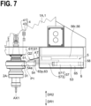
- FIG. 6 to 8 each are a schematic front view of a part of the machine tool 1A according to the first embodiment.
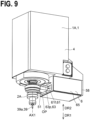
- FIG. 9 is a schematic perspective view of a part of the machine tool 1A according to the first embodiment.
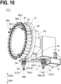
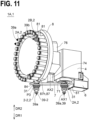
- FIGs. 10 and 11 are each a schematic perspective view of the machine tool 1A according to the first embodiment.
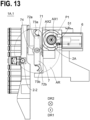
- FIGs. 12 and 13 are each a schematic bottom view of the machine tool 1A according to the first embodiment.
- FIG. 14 is a schematic perspective view of a part of a stocker 8.
- FIG. 15 is a schematic side view of a part of the stocker 8.
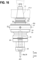
- FIG. 16 is a schematic front view of an example of the tool holder 2A.
- FIG 17 is a cross-sectional view schematically illustrating a state in which power is being supplied from the power feeding part 51 to the power receiver 31 of the tool holder 2A.
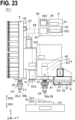
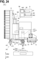
- FIGs. 18 to 26 are each a schematic front view of the machine tool 1A according to the first embodiment.
- the machine tool 1A includes the tool holder 2A, a rotation device 4, and a power feeder 5.
- the tool holder 2A is mounted on a rotation body 41 of the rotation device 4.
- the tool holder 2A holds the tool 39, which machines a workpiece.
- the tool holder 2A includes the power receiver 31 and the at least one sensor 34.
- the power receiver 31 receives power from the power feeder 5 (more specifically, the power feeding part 51 of the power feeder 5).
- the power receiver 31 is provided at an outer circumferential edge region RG of the tool holder 2A.
- the power receiver 31 is provided in a ring-shaped region RG1 and preferably along a circle centered around a first axis AX1. In this case, when the tool holder 2A rotates about the first axis AX1, power is supplied from the power feeding part 51 of the power feeder 5 to the power receiver 31 substantially without interruption.
- the region defined by two circles indicated by broken lines corresponds to the ring-shaped region RG1, in which the power receiver 31 is provided.
- the power receiver 31 may include a plurality of power receiving coils 31c.
- the plurality of power receiving coils 31c are provided in the ring-shaped region RG1 and along the circle centered around the first axis AX1.
- the at least one sensor 34 is electrically connected to the power receiver 31.
- the at least one sensor 34 is operated by the power received from the power receiver 31. In operation, the at least one sensor 34 detects a physical quantity indicating a state of the tool holder 2A.
- the rotation device 4 rotates the tool holder 2A about the first axis AX1.
- An example of the first axis AX1 is an axis perpendicular to a horizontal plane.
- the rotation device 4 preferably rotates the entire tool holder 2A about the first axis AX1.
- the rotation device 4 includes the rotation body 41.
- the rotation body 41 is rotatable about the first axis AX1. In a state in which the tool holder 2A is attached to the rotation body 41, the rotation body 41 rotates about the first axis AX1 together with the tool holder 2A.
- the rotation device 4 includes a support body 43, in addition to the rotation body 41.
- the support body 43 rotatably supports the rotation body 41.
- the power feeder 5 supplies power to the tool holder 2A.
- the power feeder 5 includes the power feeding part 51 and a first mover 53.
- the power feeding part 51 supplies power to the power receiver 31 of the tool holder 2A.
- the power feeding part 51 is a feeding coupler that supplies power to the power receiver 31.
- the power receiver 31 is a power receiving coupler that receives power from the power feeding part 51.
- the power feeding part 51 supplies power to the power receiver 31 by a non-contact method.
- the power feeding part 51 may supply power to the power receiver 31 by a contact method (more specifically, by a brush method).
- the first mover 53 moves the power feeding part 51. More specifically, the first mover 53 moves the power feeding part 51 between a power feeding position P1 (see FIG. 4 ) and a retracted position P2 (see FIG. 1 ). At the power feeding position P1, the power feeding part 51 faces the power receiver 31.
- the retracted position P2 (see FIG. 1 ) is spaced further apart from the power receiver 31 than the power feeding position P1 is spaced apart from the power receiver 31.
- the power feeding part 51 may not necessarily face all of the power receiver 31. In other words, in a state in which the power feeding part 51 is positioned at the power feeding position P1, it suffices that the power feeding part 51 faces a part of the power receiver 31.
- power can be supplied to the tool holder 2A from outside the tool holder 2A.
- the power receiver 31 is provided in the outer circumferential edge region RG of the tool holder 2A. This enables the power feeding part 51, which is provided outside the tool holder 2A, to easily approach the power receiver 31 of the tool holder 2A.
- the position of the power feeding part 51 is changeable in position between the power feeding position P1, at which the power feeding part 51 faces the power receiver 31, and the retracted position P2, which is spaced further apart from the power receiver 31.
- the power feeding part 51 is able to efficiently supply power to the power receiver 31.
- the power feeding part 51 is positioned at the retracted position P2, the power feeding part 51 does not impede processes associated with the tool holder 2A, such as replacement the tool holder 2A.
- the tool holder 2A which needs external power feeding, and a tool holder that does not need external power feeding may be selectively attached to the rotation body 41 of the rotation device 4.
- the power feeding part 51 is kept at the retracted position P2. This eliminates or minimizes attachment of powdery chips and/or chips generated from the workpiece to the power feeding part 51 positioned at the retracted position P2.
- the tool 39 held by the tool holder 2A is the friction stir welding tool 39a.
- the friction stir welding tool 39a includes a probe 392a, which is inserted in a workpiece W, and a shoulder 390a, which contacts a surface of the workpiece W.
- a shoulder surface 391a of the shoulder 390a is in contact with a surface of a first workpiece W1 and a surface of the second workpiece W2.
- FIG. 4 illustrates an example of butting joining in which faces of the two workpieces are butted and joined together.
- the two workpieces may be joined together by superimpose joining, in which the two workpieces are superimposed on each other and joined together.
- the friction stir welding tool 39a rotates about the first axis AX1 to soften a joining target portion of the first workpiece W 1 and a joining target portion of the second workpiece W2 by friction heat.
- the material softened by the friction stir welding tool 39a is caused to flow around the tool by the rotation of the tool.
- the material flowing around the friction stir welding tool 39a is solidified to join the first workpiece W1 and the second workpiece W2 together.
- the tool 39 is the friction stir welding tool 39a
- no powdery chips and/or chips are generated from the workpiece W during friction stir welding, or a very small amount of powdery chips and/or chips are generated from the workpiece W during friction stir welding. This ensures a low possibility of powdery chips and/or chips adhering to the power feeding part 51 and the power receiver 31.
- the tool 39 may be a cutting tool 39b.
- the cutting tool 39b cuts the workpiece W.
- the tool 39 is the cutting tool 39b
- the tool holder 2A includes a flange 29 to prevent powdery chips and/or chips from adhering to the power receiver 31.
- the flange 29 is provided further at the leading end side than the power receiver 31 (in other words, at the first direction DR1 side).
- the flange 29 is preferably a ring-shaped flange.
- the flange 29 is provided between the power feeding part 51 and the workpiece W.
- the power feeding part 51 is hidden behind the flange 29 in a view from a direction along the second direction DR2.
- the flange 29 prevents powdery chips and/or chips generated from the workpiece W from adhering to the power feeding part 51.
- the configuration of the flange 29 may be employed in the tool holder 2Athat holds the friction stir welding tool 39a (see, for example, FIG. 4 ).
- the tool 39 held by the tool holder 2A is the friction stir welding tool 39a.
- the tool 39 held by the tool holder 2A is the cutting tool 39b.
- the tool 39 held by the tool holder 2A may be a tool other than a friction stir welding tool and a cutting tool (for example, a measuring tool).
- the tool holder 2A may include the held part 21, the tool holding part 22, and an exposed part 23.
- the held part 21 is a part held by the rotation body 41 of the rotation device 4. In other words, the held part 21 is held by the rotation body 41 of the rotation device 4.
- the tool holding part 22 is a part that holds the tool 39.
- the tool 39 held by the tool holding part 22 may be the friction stir welding tool 39a, a cutting tool, or any other tool (for example, a measuring tool).
- the exposed part 23 is a part exposed from the rotation body 41 in a state in which the tool holder 2A is attached to the rotation body 41 of the rotation device 4. In other words, in a state in which the held part 21 is held by the rotation body 41 of the rotation device 4, the exposed part 23 is exposed from the rotation body 41 of the rotation device 4.
- the exposed part 23, which is exposed from the rotation body 41 is a combination of a plurality of members having various outer diameters or a plurality of parts having various outer diameters.
- the power receiver 31 is provided in the outer circumferential edge region RG of the exposed part 23.
- the machine tool 1A includes an air sprayer 47.
- the air sprayer 47 sprays air to the power receiver 31 of the tool holder 2A, which is holdable by the rotation body 41 of the rotation device 4.
- the air sprayer 47 sprays air to the power receiver 31 to powdery chips, chips, and/or dust adhered to the power receiver 31, blowing the powdery chips, chips, and/or dust off the power receiver 31. This prevents an instable supply of power from the power feeding part 51 to the power receiver 31, which can be otherwise caused by powdery chips, chips, and/or dust adhered to the power receiver 31.
- the air sprayer 47 may spray air to the power receiver 31 of the tool holder 2A.
- the air sprayer 47 may spray air to both the power receiver 31 of the tool holder 2A and the power feeding part 51.
- the air sprayer 47 is provided at the rotation device 4 (more specifically, the support body 43 of the rotation device 4).
- the air sprayer 47 sprays air from an end portion of the rotation device 4 at the first direction DR1 side toward the power receiver 31 of the tool holder 2A.
- the air sprayer 47 includes an air spray hole 47h, an air supply path 48, which supplies air to the air spray hole 47h, and a valve 48v, which opens and closes the air supply path 48.
- a valve 48v which opens and closes the air supply path 48.
- the valve 48v When the valve 48v is in open state, air is supplied from an air supply source to the air spray hole 47h through the air supply path 48.
- the valve 48v When, in contrast, the valve 48v is in closed state, the air supply path 48 is closed, and no air is supplied to the air spray hole 47h.
- the air supply path 48 and the valve 48v are provided at the rotation device 4 (more specifically, the support body 43 of the rotation device 4).
- the air sprayer 47 also cools the tool holder 2A held by the rotation body 41 of the rotation device 4.
- the tool holder 2A has a high temperature.
- the air sprayer 47 sprays air to the tool holder 2A after the machining of the workpiece W in order to cool the tool holder 2A.
- the machine tool exhibits enhanced user safety.
- the power feeding part 51 supplies power to the power receiver 31 by a non-contact method. More specifically, when the power feeding part 51 is positioned at the power feeding position P1, the power feeding part 51 is able to supply power to the power receiver 31 of the tool holder 2A by a non-contact method. When, in contrast, the power feeding part 51 is positioned at the retracted position P2 (see FIG. 1 ), the power feeding part 51 is unable to supply power the power receiver 31. In other words, the retracted position P2 is an unfeedable position.
- the power feeding part 51 In a case where the power feeding part 51 is able to supply power to the power receiver 31 by a non-contact method, the power feeding part 51 does not cause any mechanical obstruction to the tool holder 2A while the tool holder 2Ais rotating about the first axis AX1. Also in this case, it is not necessary to perform advanced positioning control on the power feeding part 51 relative to the power receiver 31. Further in this case, there is no wiring electrically connecting the power feeding part 51 and the power receiver 31 to each other. This ensures that the tool holder 2A held by the rotation device 4 can be easily exchanged to another tool holder.
- the power feeding part 51 supplies power to the power receiver 31 by electromagnetic induction.
- the power feeding part 51 constitutes a first inductive coupler
- the power receiver 31 constitutes a second inductive coupler that receives power from the power feeding part 51.
- the power feeding part 51 supplies power to the power receiver 31 by a proximity non-contact method.
- the distance between the power feeding part 51 and the power receiver 31 is, for example, 1.5 mm or less.
- Non-contact feeding to a rotation body is generally performed in a direction parallel to the rotation axis of the rotation body.
- the power receiver 31 receives power in a direction perpendicular to the first axis AX1. More specifically, the direction of power supply from the power feeding part 51 to the power receiver 31 is a direction perpendicular to the first axis AX1 and toward the first axis AX1.
- a straight line connecting the power feeding part 51 positioned at the power feeding position P1 to a portion of the power receiver 31 which portion faces the power feeding part 51 is preferably perpendicular to the first axis AX1.
- the first axis AX1 is perpendicular to the horizontal plane.
- the power feeding part 51 and the power receiver 31 are provided on the same horizontal plane.
- the rotation device 4 includes the rotation body 41 and the support body 43.
- the rotation body 41 holds the tool holder 2A and rotates about the first axis AX1 together with the tool holder 2A.
- the rotation body 41 preferably rotates about the first axis AX1 together with the entire tool holder 2A.
- the support body 43 supports the rotation body 41 rotatably about the first axis AX1.
- the rotation body 41 is occasionally referred to as a tool spindle, and the support body 43 is occasionally referred to as a tool headstock.
- the rotation body 41 and the support body 43 are each made up of a plurality of members.
- the rotation device 4 includes a bearing 44,which is provided between the rotation body 41 and the support body 43, and a rotary drive 45 (for example, a motor), which rotates the rotation body 41 about the first axis AX1.
- the rotary drive 45 includes a stator 45s, which is fixed to the support body 43, and a rotor 45r, which is fixed to the rotation body 41. Upon supply of current to the stator 45s, the rotor 45r is caused to rotate about the first axis AX1 by an electromagnetic effect between the stator 45s and the rotor 45r.
- the rotary drive 45 may include a motor and a transfer mechanism (such as a gear or a transmission belt) that transmits the motive power of the motor to the rotation body 41.
- the first mover 53 moves the power feeding part 51 from the retracted position P2 to the power feeding position P1 to make the power feeding part 51 near to the power receiver 31 of the tool holder 2A.
- the first mover 53 includes a moving body 54, a drive 57, and a second support body 58, which supports the drive 57.
- the power feeding part 51 is provided at the moving body 54. In this case, the power feeding part 51 moves together with the moving body 54. In the example illustrated in FIG. 7 , the power feeding part 51 is provided at a leading end portion 54e of the moving body 54.
- a leading end face 540e of the moving body 54 may have an arc shape in a view from a direction along the first axis AX1. More specifically, the leading end face 540e of the moving body 54 may have an arc shape complementary to the shape of the ring-shaped region RG1, in which the power receiver 31 is provided. In a case where the leading end face 540e of the moving body 54 has an arc shape, the leading end face 540e of the moving body 54 is nearer to the power receiver 31. In the example illustrated in FIG.
- the drive 57 moves the moving body 54.
- the drive 57 may be a motor or an actuator driven by fluid pressure.
- the drive 57 includes a cylinder 571 and a rod 573, which is capable of reciprocating relative to the cylinder 571.
- the moving body 54 is mounted on a leading end portion of the rod 573.
- the first mover 53 is supported by the support body 43 of the rotation device 4. More specifically, the second support body 58, which supports the drive 57, is fixed to the support body 43 of the rotation device 4.
- the first mover 53 In a case where the first mover 53 is supported by the support body 43 of the rotation device 4, the first mover 53 moves together with the support body 43 of the rotation device 4. Therefore, due to the movement of the support body 43 of the rotation device 4 (more specifically, the entire rotation device 4), the positional relationship between the power feeding part 51 positioned at the power feeding position P1 and the power receiver 31 of the tool holder 2A remains unchanged. Thus, even in a case where the support body 43 of the rotation device 4 (more specifically, the entire rotation device 4) moves, the supply of power from the power feeding part 51 to the power receiver 31 is maintained.
- this embodiment does not exclude any configuration in which the first mover 53 is supported by a member different from the support body 43 of the rotation device 4. It is to be noted, however, that in a case where the first mover 53 is supported by a member different from the support body 43 of the rotation device 4, it is necessary to move the power feeding part 51 in coordination with the movement of the support body 43 in order to maintain the supply of power to the power receiver 31.
- the power feeder 5 includes a guide member 56 (for example, a guide rail 56r), which guides the movement of the moving body 54.
- a guide member 56 for example, a guide rail 56r
- the first mover 53 moves the power feeding part 51 in the direction perpendicular to the first axis AX1. More specifically, a line connecting the power feeding position P1 of the power feeding part 51 to the retracted position P2 of the power feeding part 51 is perpendicular to the first axis AX1. In this case, the power feeding part 51 moves between the power feeding position P1 and the retracted position P2 by a shorter movement stroke. Also in this case, the power feeding part 51 can be moved by a simple mechanism.
- this configuration can be easily adapted to a plurality of kinds of tool holders having different sizes.
- a first-type tool holder where the distance between the first axis AX1 and the power receiver 31 is a first value is prepared, and a second-type tool holder where the distance between the first axis AX1 and the power receiver 31 is a second value different from the first value is prepared.
- the tool holder attached to the rotation device 4 is changed from the first-type tool holder to the second-type tool holder, it suffices to change the movement stroke of the power feeding part 51 based on the difference between the first value and the second value.
- the first axis AX1 is perpendicular to the horizontal plane. Also in the example illustrated in FIG. 4 , the first mover 53 moves the power feeding part 51 in a direction parallel to the horizontal plane.
- the machine tool 1A includes a storage 6.
- the storage 6 stores the power feeding part 51 positioned at the retracted position P2.
- the storage 6 has an opening OP, through which the power feeding part 51 is passable, and a closing body 61, which is capable of closing the opening OP.
- An example of the closing body 61 is a plate capable of closing the opening OP.
- the power feeding part 51 is stored in the storage 6, and the opening OP is closed by the closing body 61. This effectively prevents powdery chips, chips, and/or dust from adhering to the power feeding part 51.
- the closing body 61 is a flap 61f.
- the flap 61f is swingable about a swing axis AT between an open position Q2 (see FIG. 7 ) and a closed position Q1 (see FIG. 8 ).
- the closing body 61 may be a slide plate linearly movable between the open position Q2 and the closed position Q1.
- the power feeding part 51 of the power feeder 5 is able to supply power to the power receiver 31.
- the power feeding part 51 is protected by the closing body 61. More specifically, when the closing body 61 is positioned at the closed position Q1 and when the power feeding part 51 is positioned at the retracted position P2, the power feeding part 51 of the power feeder 5 is protected by the closing body 61. In the example illustrated in FIG. 8 , powdery chips, chips, and/or dust are prevented from adhering to the power feeding part 51 when the power feeding part 51 is not in use.
- the machine tool 1A may include a closing body mover 63.
- the closing body mover 63 moves the closing body 61.
- the closing body mover 63 moves the closing body 61 between the open position Q2 (see FIG. 7 ) and the closed position Q1 (see FIG. 8 ).
- the closing body mover 63 includes a pressing member 63p.
- the pressing member 63p is provided at the moving body 54.
- the pressing member 63p moves to press the closing body 61 so as to move the closing body 61 from the closed position Q1 to the open position Q2.
- the pressing member 63p also moves in a direction to release the pressing of the closing body 61 so as to move the closing body 61 from the open position Q2 to the closed position Q1.
- the storage 6 includes a housing 65.
- the housing 65 defines a space SP, in which the power feeding part 51 is stored.
- the housing 65 is preferably capable of storing the entire moving body 54, at which the power feeding part 51 is provided.
- the housing 65 may also house the drive 57, which moves the moving body 54.
- a drive that moves the pressing member 63p is the same as the drive 57, which moves the moving body 54. More specifically, the drive 57 integrally moves the pressing member 63p and the moving body 54. Alternatively, the drive that moves the pressing member 63p may be different from the drive 57, which moves the moving body 54.
- the machine tool 1A includes a tool exchanger 7.
- the tool exchanger 7 exchanges the tool holder 2A held by the rotation device 4 (more specifically, the rotation body of the rotation device 4) to another tool holder.
- the two tool holders exchanged by the tool exchanger 7 will be distinguished from each other. Specifically, one of the two tool holders will be referred to as “tool holder 2A”, and the other of the two tool holders will be referred to as “second tool holder 2-2".
- a tool held by the tool holder 2A and a tool held by the second tool holder 2-2 will be distinguished from each other. Specifically, the former tool will be referred to as "tool 39”, and the latter tool will be referred to as "second tool 39-2".
- the rotation device 4 (more specifically, the rotation body of the rotation device 4) is able to selectively hold the tool holder 2A and the second tool holder 2-2.
- the rotation device 4 holds the second tool holder 2-2.
- the tool holder 2A is a tool holder that includes the power receiver 31, which receives power from the power feeding part 51.
- the second tool holder 2-2 is a tool holder without a power receiver.
- An example of the second tool 39-2 held by the second tool holder 2-2 is the cutting tool 39b.
- the second tool holder 2-2 may be a tool holder that includes the power receiver 31, which receives power from the power feeding part 51.
- the second tool 39-2 may be the friction stir welding tool 39a.
- the retracted position P2 of the power feeding part 51 is set to a position outside a region AR.
- the region AR the tool exchanger 7, the tool holder 2A, and the second tool holder 2-2 pass.
- the region AR in which the tool exchanger 7, the tool holder 2A, and the second tool holder 2-2 pass, is hatched with dots to make the region AR easily recognizable.
- the power feeding part 51 does not cause any obstruction to the process of exchanging the tool holders performed by the tool exchanger 7.
- the power feeding position P1 of the power feeding part 51 is set to a position that causes obstruction to the region AR, in which the tool exchanger 7, the tool holder 2A, and the second tool holder 2-2 pass.
- the power feeding part 51 is moved from the power feeding position P1 to the retracted position P2 prior to the exchange of the tool holder 2A to the second tool holder 2-2 by the tool exchanger 7.
- the tool exchanger 7 includes a tool exchange arm 71, an arm rotation device 74, which rotates the tool exchange arm 71, and an arm mover 76, which linearly moves the tool exchange arm 71.
- the arm rotation device 74 rotates the tool exchange arm 71 about a second axis AX2.
- the arm mover 76 moves the tool exchange arm 71 in a direction parallel to the second axis AX2.
- the tool exchange arm 71 includes a first arm 72a and a second arm 72b.
- the first arm 72a includes a first gripper 73a, which is capable of gripping the tool holder 2A.
- the second arm 72b includes a second gripper 73b, which is capable of gripping the second tool holder 2-2.
- the angle defined between the first arm 72a and the second arm 72b is 180 degrees.
- the angle defined between the first arm 72a and the second arm 72b may be an angle other than 180 degrees.
- the tool exchange arm 71 (more specifically, the first arm 72a and the second arm 72b) is rotatable about the second axis AX2.
- the second axis AX2 is parallel to the first axis AX1.
- the machine tool 1A includes a stocker 8.
- the stocker 8 is capable of storing the tool holder 2A and the second tool holder 2-2.
- the stocker 8 is capable of storing a plurality of tool holders 2 including the tool holder 2A and the second tool holder 2-2.
- the stocker 8 is preferably capable of storing both the tool holder 2A and a tool holder 2B.
- the tool holder 2A includes the power receiver 31, which is capable of receiving power from the power feeding part 51.
- the tool holder 2B is without a power receiver.
- the stocker 8 is preferably capable of storing both a tool holder 2A that holds the friction stir welding tool 39a and a tool holder 2B that holds the cutting tool 39b.
- the stocker 8 includes a plurality of holding parts 81, which hold the plurality of respective tool holders 2; and a holding part mover 82, which moves the plurality of holding parts 81 along a circumferential orbit.
- the stocker 8 may include a holder takeout device 84.
- the holder takeout device 84 moves a tool holder 2 stored in the stocker 8 to a waiting position P3.
- the waiting position P3 is accessible by the tool exchanger 7.
- the stocker 8 may include an air sprayer 87 (which includes, for example, an air spray hole 87h and an air supplier that supplies air to the air spray hole 87h).
- the air sprayer 87 sprays air.
- the air sprayer 87 sprays air to the tool holders 2 stored in the stocker 8 or to a tool holder 2 taken out of the stocker 8. By spraying air to a tool holder 2, the tool holder 2 is cooled.
- the stocker 8 may include a protection cover 85.
- the protection cover 85 protects the power receiver 31 of the tool holder 2A.
- the protection cover 85 covers at least a part of the power receiver 31.
- the protection cover 85 covers only a part of the power receiver 31 of the tool holder 2A stored in the stocker 8.
- the protection cover 85 may cover the entire power receiver 31 of the tool holder 2A stored in the stocker 8.
- the protection cover 85 includes a base 85a and an openable-closable member 85b. At the time of tool exchange, the openable-closable member 85b is moved to an open position.
- the openable-closable member 85b does not cause any obstruction to a tool exchange motion.
- the openable-closable member 85b is moved to a closed position.
- the power receiver 31 is covered by the base 85a and the openable-closable member 85b.
- the openable-closable member 85b may be configured to move in coordination with the movement of the tool exchange arm.
- the protection cover 85 prevents these droplets, powdery chips, chips, and/or dust from adhering to the power receiver 31.
- the protection cover 85 may be mounted on the holding part 81 holding the tool holder 2, or may be mounted on a member other than the holding part 81.
- the tool holder 2A includes the held part 21, which is held by the rotation device 4 (more specifically, the rotation body 41 of the rotation device 4), the tool holding part 22, which holds the tool 39, and a center portion 24, which is provided between the held part 21 and the tool holding part 22.
- the held part 21 is a base end portion of the tool holder 2A
- the tool holding part 22 is a leading end portion of the tool holder 2A.
- the held part 21 has, for example, a tapered shape whose outer diameter decreases in the second direction DR2 (for example, an approximately circular conical shape).
- the center portion 24 is a combination of a plurality of members having various outer diameters or a plurality of parts having various outer diameters.
- the power receiver 31 is provided in the outer circumferential edge region RG of the center portion 24.
- a first plane PL1 passes an end 22s of the tool holder 2A at the first direction DR1 side and is perpendicular to the first axis AX1.
- a second plane PL2 passes an end of the power receiver 31 at the first direction DR1 side and is perpendicular to the first axis AX1.
- the distance between the first plane PL1 and the second plane PL2 is defined as first distance L1.
- a third plane PL3 passes an end of the power receiver 31 at the second direction DR2 side and is perpendicular to the first axis AX1.
- a fourth plane PL4 passes an end of the held part 21 at the first direction DR1 side and is perpendicular to the first axis AX1.
- the distance between the third plane PL3 and the fourth plane PL4 is defined as second distance L2 .
- the first distance L1 is greater than the second distance L2. In a case where the first distance L1 is relatively greater, powdery chips and/or chips generated from the workpiece W are less likely to adhere to the power receiver 31.
- the tool holder 2A includes a gripped part 25.
- the gripped part 25 is grippable by the tool exchange arm 71 of the tool exchanger 7.
- the gripped part 25 may have a groove 25v (more specifically, an annular groove). In the groove 25v, a part of the tool exchange arm 71 is insertable.
- the power receiver 31 is provided further at the first direction DR1 side than the gripped part 25.
- the power receiver 31 is preferably provided a position adjacent to the gripped part 25. In a case where the power receiver 31 is provided adjacent to the gripped part 25, the first distance L1 increases. This ensures that powdery chips and/or chips generated from the workpiece W are less likely to adhere to the power receiver 31.
- the outer circumferential edge region RG in which the power receiver 31 is provided, has an outer diameter of D1.
- the outer diameter D1 is greater than a maximum outer diameter D2 of the gripped part 25.
- the power receiver 31 is provided in a region further away from the first axis AX1 than an outermost edge of the gripped part 25 is away from the first axis AX1. This enables the power feeding part 51 to easily approach the power receiver 31.
- the power receiver 31 may be provided in a region nearer to the first axis AX1 than the outermost edge of the gripped part 25 is near to the first axis AX1. In this case, the power receiver 31 becomes smaller in size, resulting in a reduction in the weight of the tool holder 2A.
- the tool holder 2A includes a sensor 34.
- the sensor 34 is electrically connected to the power receiver 31 to consume the power received from the power receiver 31.
- the sensor 34 is operated by the power received from the power receiver 31.
- the sensor 34 and the power receiver 31 are connected to each other via a conductive wire 32.
- the sensor 34 in a direction along the first axis AX1, the sensor 34 is provided further at the first direction DR1 side than the power receiver 31. More specifically, in the direction along the first axis AX1, the sensor 34 is provided between the tool holding part 22 and the power receiver 31 of the tool holder 2A. By providing the sensor 34 between the tool holding part 22 and the power receiver 31, the first distance L1 increases. This ensures that powdery chips and/or chips generated from the workpiece W are less likely to adhere to the power receiver 31.
- the at least one sensor 34 includes a load sensor 34a.
- the load sensor 34a detects a load that the tool holder 2A receives from the tool 39 (for example, the friction stir welding tool 39a). It is to be noted that the load that the tool holder 2A receives from the tool 39 is one of a plurality of physical quantities indicating a state of the tool holder 2A.
- a slide member 37 is provided between the load sensor 34a and the tool 39.
- the slide member 37 is movable in a direction parallel to the first axis AX1.
- the load sensor 34a detects a load that the tool holder 2A receives from the tool 39 via the slide member 37.
- the at least one sensor 34 may include a temperature sensor 34b.
- the temperature sensor 34b detects a temperature of the tool holder 2A.
- the temperature of the tool holder 2A is one of a plurality of physical quantities indicating a state of the tool holder 2A.
- the at least one sensor 34 may include a vibration sensor 34c.
- the vibration sensor 34c detects a vibration of the tool holder 2A.
- the vibration sensor 34c may be an acceleration sensor.
- the vibration of the tool holder 2A is one of a plurality of physical quantities indicating a state of the tool holder 2A.
- the at least one sensor 34 may include a sensor other than the load sensor 34a, the temperature sensor 34b, and the vibration sensor 34c.
- the tool holder 2A includes a transmitter 35.
- the transmitter 35 receives a sensor signal from the sensor 34 and transmits the sensor signal to a signal receiver 52.
- the signal receiver 52 is provided outside the tool holder 2A.
- the transmitter 35 preferably transmits the sensor signal received from the sensor 34 to the signal receiver 52 by a wireless method.
- the transmitter 35 includes a transmission antenna 35a.
- the transmission antenna 35a transmits the sensor signal to the signal receiver 52 by a wireless method.
- the transmitter 35 is electrically connected to the sensor 34.
- the sensor 34 and the transmitter 35 are connected to each other via a second conductive wire 36.
- the transmitter 35 transmits the sensor signal received from the sensor 34 to a controller 9, described later, via the signal receiver 52.
- the transmitter 35 is provided in the outer circumferential edge region RG of the tool holder 2A (more specifically, the outer circumferential edge region RG of the exposed part 23).
- the transmitter 35 is preferably provided at the power receiver 31 or near the power receiver 31. In this case, a compact electric system can be implemented for the tool holder 2A, including the transmitter 35 and the power receiver 31.
- the sensor 34 transmits the sensor signal to the transmitter 35.
- the transmitter 35 then transmits the sensor signal to the signal receiver 52.
- FIG. 17 the example illustrated in FIG.
- the transmitter 35 when the power feeding part 51 is positioned at the power feeding position, the transmitter 35 is able to transmit the sensor signal to the signal receiver 52 by a non-contact method (more specifically, by a proximity non-contact method). It is to be noted that in this embodiment, the position at which the transmitter 35 is provided will not be limited to the power receiver 31 or near the power receiver 31. The transmitter 35 of the tool holder 2A may be provided at any other position at which the transmitter 35 is able to wirelessly communicate with the signal receiver 52.
- the power receiver 31 and the transmitter 35 are provided along the direction parallel to the first axis AX1.
- the power receiver 31 and the transmitter 35 may be provided along a circumferential direction of a circle centered around the first axis AX1.
- the transmitter 35 transmits a first sensor signal to the signal receiver 52.
- the first sensor signal indicates the load detected by the load sensor 34a.
- the transmitter 35 may transmit a second sensor signal to the signal receiver 52.
- the second sensor signal indicates the temperature detected by the temperature sensor 34b.
- the transmitter 35 may transmit a third sensor signal to the signal receiver 52.
- the third sensor signal indicates the vibration detected by the vibration sensor 34c.
- the first sensor signal, the second sensor signal, and the third sensor signal may be transmitted from the transmitter 35 to the signal receiver 52 simultaneously.
- the first sensor signal, the second sensor signal, and the third sensor signal may be transmitted from the transmitter 35 to the signal receiver 52 in order.
- each of the first sensor signal, the second sensor signal, and the third sensor signal may be transmitted from the transmitter 35 to the signal receiver 52 at predetermined time intervals.
- a transmission antenna 35a may be prepared on a sensor-signal basis.
- the transmitter 35 may include a plurality of transmission antennas 35a.
- the power feeder 5 includes the signal receiver 52. More specifically, the signal receiver 52, which receives the sensor signal from the transmitter 35, is provided at the leading end portion 54e of the moving body 54 of the power feeder 5. In this case, the signal receiver 52 is able to stably receive the sensor signal from the transmitter 35, which is provided in the outer circumferential edge region RG of the tool holder 2A.
- the signal receiver 52 is preferably provided at the power feeding part 51 or near the power feeding part 51. It is to be noted, however, that in this embodiment, the position at which the signal receiver 52 is provided will not be limited to near the power feeding part 51.
- the signal receiver 52 may be provided at any position at which the signal receiver 52 is able to wirelessly communicate with the transmitter 35.
- the signal receiver 52 may be provided at a member other than the moving body 54.
- the controller 9 for example, a communication circuit of the controller 9, described later, may function as the signal receiver 52 to receive the sensor signal directly from the transmitter 35.
- the power feeding part 51 and the signal receiver 52 are provided along the direction parallel to the first axis AX1.
- the power feeding part 51 and the signal receiver 52 may be provided along the arc shape of the leading end face 540e of the arc-shaped moving body 54.
- the machine tool 1A includes a workpiece support member 101.
- the workpiece support member 101 supports the workpiece W, which is a to-be-worked object (for example, a joined object).
- An example of the workpiece support member 101 is a support table to which the workpiece W is fixed.
- the workpiece support member 101 supports both the first workpiece W1 and the second workpiece W2 in a state in which a side surface of the first workpiece W1 and a side surface of the second workpiece W2 contact each other.
- the machine tool 1A includes a second mover 102.
- the second mover 102 moves the tool holder 2A held by the rotation body 41 of the rotation device 4 relative to the workpiece support member 101.
- the second mover 102 is preferably capable of moving the tool holder 2A at least in a direction parallel to the vertical direction.
- the second mover 102 may be a device capable of moving the tool holder 2A two-dimensionally or three-dimensionally.
- the second mover 102 may be capable of moving the tool holder 2A only in a direction along one of X axis or Y axis and capable of moving the tool holder 2A in a direction along the Z axis.
- the second mover 102 may be capable of moving the tool holder 2A in a direction along the X axis, capable of moving the tool holder 2Ain a direction along the Y axis, and capable of moving the tool holder 2A in the direction along the Z axis.
- the Z axis is an axis perpendicular to the horizontal plane
- the X axis is an axis parallel to the horizontal plane
- the Y axis is an axis perpendicular to both the Z axis and the X axis.
- the second mover 102 moves the tool holder 2Aby moving the support body 43 of the rotation device 4. More specifically, when the second mover 102 moves the support body 43, the entire rotation device 4, the tool holder 2A held by the rotation device 4, and the tool 39 held by the tool holder 2A move relative to the workpiece support member 101 and the workpiece W supported by the workpiece support member 101.
- the machine tool 1A may include a third mover 103.
- the third mover 103 moves the workpiece support member 101.
- the third mover 103 is a device that moves the workpiece support member 101 in, for example, a direction along the horizontal plane (in other words, a direction along the X-Y plane).
- the machine tool 1A includes the controller 9.
- the controller 9 may be implemented by a single computer or a plurality of computers.
- the controller 9 includes a processor 91, a memory 92, a communication circuit 93, and an input device 94 (for example, touch panel-equipped display 942).
- the processor 91, the memory 92, the communication circuit 93, and the input device 94 are connected to each other via a bus 95.
- Data necessary for the machining of the workpiece W may be input to the controller 9 via the input device 94, or may be input to the controller 9 from another computer via the communication circuit 93.
- the input device 94 will not be limited to the touch panel-equipped display 942.
- the controller 9 may include: the input device 94, such as a button, a switch, a lever, a pointing device, and a keyboard; and a display that displays data input to the input device 94 or other information.
- the processor 91 executes a machining program 922, which is stored in the memory 92, to generate a control signal.
- the communication circuit 93 transmits the control signal to a control target instrument(s) (for example, the first mover 53, the power feeder 5, the rotation device 4, the second mover 102 and/or the third mover 103, the air sprayer 47 and/or the air sprayer 87, the stocker 8, and the tool exchanger 7).
- a control target instrument(s) for example, the first mover 53, the power feeder 5, the rotation device 4, the second mover 102 and/or the third mover 103, the air sprayer 47 and/or the air sprayer 87, the stocker 8, and the tool exchanger 7.
- the machining program 922 may include a first program for performing a first machining mode, described later.
- the machining program 922 may also include a second program for performing a second machining mode, described later.
- the machining program 922 may also include a third program for performing a tool exchange mode, described later.
- the controller 9 transmits a control signal to the first mover 53 (more specifically, the drive 57 of the first mover 53) to move the power feeding part 51 to the power feeding position P1.
- this control signal will be hereinafter referred to as "first control signal S1”.
- the controller 9 also transmits a control signal to the power feeder 5 to supply power to the power feeding part 51.
- This control signal will be hereinafter referred to as "second control signal S2”.
- the controller 9 also transmits a control signal to the rotation device 4 (more specifically, the rotary drive 45 of the rotation device 4). This control signal will be hereinafter referred to as "third control signal S3".
- the controller 9 also transmits a control signal to the second mover 102.
- This control signal will be hereinafter referred to as "fourth control signal S4".
- the controller 9 also transmits a control signal to the air sprayer 47 (more specifically, the valve 48v of the air sprayer 47). This control signal will be hereinafter referred to as “fifth control signal S5".
- the controller 9 also transmits a control signal to the first mover 53 (more specifically, the drive 57 of the first mover 53) to move the power feeding part 51 to the retracted position P2.
- This control signal will be hereinafter referred to as “sixth control signal S6”.
- the controller 9 also transmits a control signal to the stocker 8. This control signal will be hereinafter referred to as “seventh control signal S7”.
- the controller 9 also transmits a control signal to the tool exchanger 7. This control signal will be hereinafter referred to as "eighth control signal S8".
- the controller 9 controls the first mover 53. More specifically, the controller 9 transmits the first control signal S1 to the first mover 53. Upon receipt of the first control signal S1, the first mover 53 moves the power feeding part 51 from the retracted position P2 to the power feeding position P1 (see FIG. 20 ).
- the controller 9 controls the power feeder 5. More specifically, the controller 9 transmits the second control signal S2 to the power feeder 5. Upon receipt of the second control signal S2, the power feeder 5 supplies power to the power receiver 31 of the tool holder 2A via the power feeding part 51, which is provided at the moving body 54. Also, the power receiver 31 of the tool holder 2A supplies power to the sensor 34. Thus, the sensor 34 (for example, the load sensor 34a, the temperature sensor 34b, and the vibration sensor 34c) is operated by the power received from the power receiver 31.
- the sensor 34 for example, the load sensor 34a, the temperature sensor 34b, and the vibration sensor 34c
- the transmitter 35 of the tool holder 2A transmits the sensor signal indicating the physical quantity detected by the sensor 34 to the controller 9 via the signal receiver 52.
- the transmitter 35 transmits the first sensor signal to the controller 9 via the signal receiver 52.
- the first sensor signal indicates the load detected by the load sensor 34a (more specifically, the load that the tool holder 2A receives from the tool 39).
- the transmitter 35 may transmit the second sensor signal to the controller 9 via the signal receiver 52.
- the second sensor signal indicates the temperature detected by the temperature sensor 34b (more specifically, the temperature of the tool holder 2A).
- the transmitter 35 may also transmit the third sensor signal to the controller 9 via the signal receiver 52.
- the third sensor signal indicates the vibration detected by the vibration sensor 34c (more specifically, the vibration of the tool holder 2A).
- the controller 9 controls the rotation device 4. More specifically, the controller 9 transmits the third control signal S3 to the rotation device 4. Upon receipt of the third control signal S3, the rotation device 4 rotates the rotation body 41 holding the tool holder 2A about the first axis AX1. Thus, the workpiece W is machined by the tool 39 held by the tool holder 2A. For example, the first workpiece W1 and the second workpiece W2 are joined together by friction stir welding by the tool 39 held by the tool holder 2A.
- the controller 9 controls the second mover 102. More specifically, the controller 9 transmits the fourth control signal S4 to the second mover 102. Upon receipt of the fourth control signal S4, the second mover 102 moves the rotation device 4, the tool holder 2A held by the rotation body 41 of the rotation device 4, and the tool 39 held by the tool holder 2A relative to the workpiece support member 101 (or the workpiece W supported by the workpiece support member 101).
- the controller 9 transmits the third control signal S3 to the rotation device 4.
- the controller 9 may transmit the fourth control signal S4 to the second mover 102.
- the rotation device 4 rotates the rotation body 41 holding the tool holder 2A about the first axis AX1.
- the fourth control signal S4 Upon receipt of the fourth control signal S4, the second mover 102 moves the tool holder 2A to change the machining position on the workpiece W.
- the workpiece W is machined, and the machining position on the workpiece W is changed at the same time.
- the machining position on the workpiece W may be changed by controlling the third mover 103 by the controller 9.
- the controller 9 may control the second mover 102 and/or the rotation device 4 based on the sensor signal received from the sensor 34 of the tool holder 2A.
- the controller 9 may, based on the first sensor signal received from the load sensor 34a of the tool holder 2A, control the second mover 102 to reduce a variation in the load that the tool holder 2A receives from the tool 39. For example, the controller 9 may control the second mover 102 so that the load detected by the load sensor 34a (in other words, the load that the tool holder 2A receives from the tool 39) becomes a target load.
- the controller 9 controls the second mover 102 to move the tool holder 2A in a direction in which the tool holder 2A retracts from the workpiece W (in the example illustrated in FIG. 21 , the upward direction). If the load detected by the load sensor 34a is lower than the target load, the controller 9 controls the second mover 102 to move the tool holder 2A in a direction toward the workpiece W (in the example illustrated in FIG. 21 , the downward direction).
- To reduce the variation in the load that the tool holder 2A receives from the tool 39 means to reduce a variation in the force that the tool 39 applies to the workpiece W. Therefore, by reducing the variation in the load that the tool holder 2A receives from the tool 39, the workpiece W is machined more stably.
- the tool 39 held by the tool holder 2A is the friction stir welding tool 39a
- the first workpiece W1 and the second workpiece W2 are joined together by friction stir welding more stably.
- the controller 9 may, based on the second sensor signal received from the temperature sensor 34b of the tool holder 2A, control the second mover 102 to prevent an excessive increase in the temperature of the tool holder 2A. More specifically, if the temperature detected by the temperature sensor 34b (in other words, the temperature of the tool holder 2A) exceeds a first threshold, the controller 9 may control the second mover 102 to move the tool holder 2A in the direction in which the tool holder 2A retracts from the workpiece W (in the example illustrated in FIG. 21 , the upward direction).
- the workpiece W is machined more stably. Also, by preventing an excessive increase in the temperature of the tool holder 2A, damage to the tool holder 2A (for example, damage to the sensor 34) and/or damage to the tool 39 are prevented.
- the controller 9 may, based on the third sensor signal received from the vibration sensor 34c of the tool holder 2A, control the second mover 102 to prevent an excessive degree of vibration of the tool holder 2A. More specifically, if the vibration detected by the vibration sensor 34c (in other words, the vibration of the tool holder 2A) exceeds a predetermined threshold, the controller 9 may control the second mover 102 to move the tool holder 2A in the direction in which the tool holder 2A retracts from the workpiece W (in the example illustrated in FIG. 21 , the upward direction).
- the workpiece W is machined more stably. Also, by preventing an excessive degree of vibration of the tool holder 2A, damage to the tool holder 2A and/or damage to the tool 39 are prevented.
- the controller 9 controls the air sprayer 47. More specifically, the controller 9 transmits the fifth control signal S5 to the air sprayer 47. Upon receipt of the fifth control signal S5, the air sprayer 47 sprays air to the tool holder 2A (for example, the power receiver 31 of the tool holder 2A).
- the controller 9 may, based on the second sensor signal received from the temperature sensor 34b of the tool holder 2A, control the air sprayer 47 to keep the temperature of the tool holder 2A at a second threshold or less.
- the controller 9 may control both the rotary drive 45 and the air sprayer 47 of the rotation device 4 to spray air to the tool holder 2A in a state in which the tool holder 2A is rotating about the first axis AX1. In this case, the removal of powdery chips, chips, and/or dust off the tool holder 2A and the cooling of the tool holder 2A are efficiently performed.
- the air sprayer 47 sprays air to the tool holder 2A in a state in which the power feeding part 51 is positioned at the power feeding position P1. In this case, air is sprayed to the power feeding part 51 as well.
- the air sprayer 47 may spray air to the tool holder 2A after the power feeding part 51 has been moved to the retracted position P2.
- the air sprayer 47 may receive the fifth control signal S5 from the controller 9 before the start of machining of the workpiece W (for example, immediately after the tool holder 2A is attached to the rotation device 4). Then, based on the fifth control signal S5, the air sprayer 47 may spray air to the tool holder 2A. In this case, powdery chips, chips, and/or dust are removed off the power feeding part 51 prior to the machining of the workpiece W.
- the controller 9 controls the first mover 53 to move the power feeding part 51 to the retracted position P2. More specifically, the controller 9 transmits the sixth control signal S6 to the first mover 53. Upon receipt of the sixth control signal S6, the first mover 53 moves the power feeding part 51 from the power feeding position P1 to the retracted position P2 (see FIG. 23 ). It is to be noted that the power feeding part 51 positioned at the retracted position P2 is preferably stored in the storage 6. Also, in a state in which the power feeding part 51 is positioned at the retracted position P2, the opening OP of the storage 6 is preferably closed by the closing body 61.
- the controller 9 controls the stocker 8. More specifically, the controller 9 transmits the seventh control signal S7 to the stocker 8 (for example, the holding part mover 82 and/or the holder takeout device 84). Upon receipt of the seventh control signal S7, the stocker 8 moves the second tool holder 2-2 stored in the stocker 8 to the waiting position P3, which is accessible by the tool exchanger 7.
- the seventh control signal S7 for example, the holding part mover 82 and/or the holder takeout device 84.
- the second tool holder 2-2 is a holder without a power receiver (more specifically, a purely mechanical holder).
- the second tool holder 2-2 is holding the cutting tool 39b.
- the second tool holder 2-2 may be a holder including the power receiver 31 (in other words, a holder including a sensor operated by the power supplied from the power receiver 31). Also, the second tool holder 2-2 may hold the friction stir welding tool 39a.
- the controller 9 controls the tool exchanger 7. More specifically, the controller 9 transmits the eighth control signal S8 to the tool exchanger 7. Upon receipt of the eighth control signal S8, the tool exchanger 7 exchanges the tool holder 2A held by the rotation body 41 of the rotation device 4 to the second tool holder 2-2.
- FIG. 25 illustrates how the tool holder 2A held by the rotation body 41 of the rotation device 4 is exchanged to the second tool holder 2-2 and how the rotation body 41 of the rotation device 4 holds the second tool holder 2-2.
- the controller 9 may control the air sprayer 87, which is provided at the stocker 8. More specifically, upon receipt of the control signal from the controller 9, the air sprayer 87 may spray air to the tool holder 2A stored in the stocker 8. In this case, the tool holder 2A having a raised temperature due to the machining of the workpiece is cooled, and the cooled tool holder 2A is stored in the stocker 8. Alternatively, upon receipt of the control signal from the controller 9, the air sprayer 87 may spray air to the tool holder 2A taken out of the stocker 8.
- the controller 9 is capable of performing the first machining mode by controlling the first mover 53, the power feeder 5, the rotation device 4, and the second mover 102.
- the first machining mode is a mode in which the workpiece W is machined by the tool 39 (for example, the friction stir welding tool 39a) held by the tool holder 2Ain a state in which the power is being supplied from the power feeding part 51 positioned at the power feeding position P1 to the power receiver 31 of the tool holder 2A.
- the first mover 53 moves the power feeding part 51 from the retracted position P2 (see FIG. 19 ) to the power feeding position P1 (see FIG. 20 ).
- the power feeder 5 supplies power to the sensor 34 via the power feeding part 51 and the power receiver 31 (see FIG. 20 ).
- the sensor 34 turns into operation state.
- the sensor 34 in operation state detects a physical quantity indicating a state of the tool holder 2A, and transmits the sensor signal indicating the physical quantity to the controller 9 (examples of the sensor signal including the first sensor signal, which indicates the load that the tool holder 2A receives from the tool 39, the second sensor signal, which indicates the temperature of the tool holder 2A, and the third sensor signal, which indicates the vibration of the tool holder 2A).
- the rotation device 4 rotates the tool holder 2A and the tool 39 held by the tool holder 2A (for example, the friction stir welding tool 39a) about the first axis AX1 and via the rotation body 41.
- the second mover 102 moves the tool holder 2A and the tool 39 held by the tool holder 2A relative to the workpiece W to cause the tool 39 (for example, the friction stir welding tool 39a) to machine the workpiece W.
- the first mover 53, the power feeder 5, the rotation device 4 and the second mover 102 cooperate to cause the tool 39 held by the tool holder 2A to machine the workpiece W.
- the sensor 34 of the tool holder 2A is operated by the power supplied via the power receiver 31. This enables the sensor 34 of the tool holder 2A to detect a physical quantity indicating a state of the tool holder 2A during the machining of the workpiece.
- the controller 9 may control the second mover 102 and/or the rotary drive 45 based on the sensor signal received from the sensor 34 of the tool holder 2A.
- the controller 9 controls the second mover 102 based on the first sensor signal received from the load sensor 34a of the tool holder 2A.
- the controller 9 may control the second mover 102 so that the load detected by the load sensor 34a of the tool holder 2A (in other words, the load that the tool holder 2A receives from the tool 39) becomes the target load. More specifically, if the load that the tool holder 2A receives from the tool 39 exceeds the target load, the controller 9 controls the second mover 102 to move the tool holder 2A in the direction in which the tool holder 2A retracts from the workpiece W (in the example illustrated in FIG. 21 , the upward direction).
- the controller 9 controls the second mover 102 to move the tool holder 2A in the direction toward the workpiece W (in the example illustrated in FIG. 21 , the downward direction).
- the controller 9 may control the second mover 102 and/or the rotary drive 45 based on the second sensor signal received from the temperature sensor 34b of the tool holder 2A. For example, if the temperature of the tool holder 2A exceeds the first threshold, the controller 9 may control the second mover 102 to move the tool holder 2A in the direction in which the tool holder 2A retracts from the workpiece W (in the example illustrated in FIG. 21 , the upward direction). Alternatively or additionally, if the temperature of the tool holder 2A exceeds the first threshold, the controller 9 may control the rotary drive 45 to decrease the rotational speed of the tool holder 2A.
- the controller 9 may control the second mover 102 and/or the rotary drive 45 based on the third sensor signal received from the vibration sensor 34c of the tool holder 2A. For example, if the vibration of the tool holder 2A exceeds the predetermined threshold, the controller 9 may control the second mover 102 to move the tool holder 2A in the direction in which the tool holder 2A retracts from the workpiece W (in the example illustrated in FIG. 21 , the upward direction). Alternatively or additionally, if the vibration of the tool holder 2A exceeds the predetermined threshold, the controller 9 may control the rotary drive 45 to decrease the rotational speed of the tool holder 2A.
- the first mover 53 may move the power feeding part 51 from the power feeding position P1 (see FIG. 22 ) to the retracted position P2 (see FIG. 23 ). Also, the power feeding part 51 positioned at the retracted position P2 may be stored in the storage 6.
- the controller 9 may control the air sprayer 47. More specifically, in the final phase of the first machining mode by the controller 9 (more specifically, after completion of the machining of the workpiece W using the tool 39), upon receipt of the fifth control signal S5 from the controller 9, the air sprayer 47 (see, if necessary, FIG. 22 ) may spray air to the tool holder 2A held by the rotation body 41 of the rotation device 4. Alternatively or additionally, during the machining of the workpiece W, the air sprayer 47 may spray air to the tool holder 2A held by the rotation body 41 of the rotation device 4 to prevent chips from adhering to the tool holder 2A.
- the controller 9 is capable of performing the second machining mode by controlling the rotation device 4 and the second mover 102.
- the second machining mode is a mode in which the workpiece is machined by the second tool 39-2 (for example, the cutting tool 39b) held by the second tool holder 2-2 in a state in which the power feeding part 51 is positioned at the retracted position P2.
- the workpiece machined by performing the second machining mode may be the same workpiece as the workpiece W machined by performing the first machining mode, or may be a workpiece different from the workpiece W machined by performing the first machining mode (this different workpiece will be hereinafter referred to as "the other workpiece").
- the power feeding part 51 is preferably stored in the storage 6. In this case, powdery chips and/or chips are prevented from adhering to the power feeding part 51 while the second machining mode is being performed.
- the rotation device 4 rotates the second tool holder 2-2 and the second tool 39-2 (for example, the cutting tool 39b) held by the second tool holder 2-2 about the first axis AX1 via the rotation body 41.
- the second mover 102 moves the second tool holder 2-2 and the second tool 39-2 held by the second tool holder 2-2 relative to the workpiece W to cause the second tool 39-2 (for example, the cutting tool 39b) to machine the workpiece W.
- the rotation device 4 and the second mover 102 cooperate to cause the second tool 39-2 held by the second tool holder 2-2 to machine the workpiece W.
- the controller 9 is capable of performing the tool exchange mode by controlling the tool exchanger 7 and the stocker 8. As exemplified in FIG. 23 , when the tool exchange mode is performed by the controller 9, the power feeding part 51 is preferably stored in the storage 6. In this case, while the tool exchange mode is being performed, the tool exchanger 7, the tool holder 2A, and the second tool holder 2-2 are prevented from colliding with the power feeding part 51.
- the stocker 8 moves the second tool holder 2-2 stored in the stocker 8 to the waiting position P3, which is accessible by the tool exchanger 7 (see FIG. 23 ).
- the tool exchanger 7 exchanges the tool holder 2A held by the rotation device 4 to the second tool holder 2-2 (see FIGs. 23 to 25 ).
- FIG. 27 is a schematic front view of the machine tool 1B according to the second embodiment.
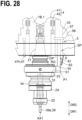
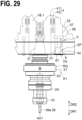
- FIGs. 28 and 29 are each a schematic front view of a part of the machine tool 1B according to the second embodiment.
- the machine tool 1B includes (1) the rotation device 4, which includes the rotation body 41, which rotates about the first axis AX1, (2) the tool holder 2A, which is attachable to the rotation body 41, and (3) the power feeder 5, which supplies power to the tool holder 2A.
- the tool holder 2A includes (4) the power receiver 31, which is provided in the outer circumferential edge region RG of the tool holder 2A, and (5) the at least one sensor 34, which is electrically connected to the power receiver 31.
- the power feeder 5 includes (6) the power feeding part 51, which supplies power to the power receiver 31, and (7) the first mover 53, which moves the power feeding part 51 between the power feeding position P1, which faces the power receiver 31 (see FIG. 28 ), and the retracted position P2 (see FIG. 29 ), which is spaced further apart from the power receiver 31 than the power feeding position P1.
- the second embodiment provides effects similar to the effects of the first embodiment.
- the machine tool 1B according to the second embodiment different from the machine tool 1A according to the first embodiment in the movement direction of the power feeding part 51 and the arrangement of the storage 6.
- the machine tool 1B according to the second embodiment is otherwise similar to the machine tool 1A according to the first embodiment.
- the following description of the second embodiment will focus on the movement direction of the power feeding part 51, configurations associated with the movement direction of the power feeding part 51, the arrangement of the storage 6, and configurations associated with the arrangement of the storage 6; description of other configurations will be omitted where otherwise a repetition of description occurs.
- the first mover 53 includes the moving body 54, the drive 57, and the second support body 58, which supports the drive 57.
- the drive 57 moves the moving body 54, at which the power feeding part 51 is provided.
- the drive 57 may be a motor or an actuator driven by fluid pressure.
- the first mover 53 is supported by the support body 43 of the rotation device 4. More specifically, the second support body 58, which supports the drive 57, is fixed to the support body 43 of the rotation device 4.
- the first mover 53 moves the power feeding part 51 in the direction parallel to the first axis AX1. More specifically, a line connecting the power feeding position P1 of the power feeding part 51 to the retracted position P2 of the power feeding part 51 is parallel to the first axis AX1. In this case, the power feeding part 51 moves between the power feeding position P1 and the retracted position P2 by a shorter movement stroke. Also in this case, the power feeding part 51 can be moved by a simple mechanism.
- the power feeding part 51 is moved in the direction perpendicular to the first axis AX1.
- the power feeding part 51 moved in the direction parallel to the first axis AX1.
- the movement direction of the power feeding part 51 may be a direction inclined relative to the horizontal plane and vertical plane. In this case, however, the movement stroke of the power feeding part 51 increases.
- the machine tool 1B includes the storage 6, which stores the power feeding part 51 positioned at the retracted position P2.
- the storage 6 has the opening OP (see FIG. 28 ), through which the power feeding part 51 is passable; and the closing body 61, which is capable of closing the opening OP.
- the space SP, in which the power feeding part 51 is stored, is formed in the support body 43 of the rotation device 4.
- FIG. 30 is a schematic cross-sectional view of the tool holder 2A according to the third embodiment.
- the tool holder 2A includes (1) the held part 21 held by the rotation device of the machine tool rotatably about the first axis AX1, (2) the tool holding part 22, which hold a tool, (3) the gripped part 25, which is provided between the held part 21 and the tool holding part 22 in the direction along the first axis AX1 and which is grippable by a tool exchange arm, (4) the power receiver 31, which is provided in the outer circumferential edge region RG, which is located between the held part 21 and the tool holding part 22 in the direction along the first axis AX1, and which receives power from the power feeding part of the machine tool by a non-contact method, and (5) the at least one sensor 34, which is electrically connected to the power receiver 31.
- the tool holder 2A according to the third embodiment is attached to the rotation device 4 (more specifically, the rotation body 41 of the rotation device 4) described in the first or second embodiment.
- the third embodiment provides effects similar to the effects provided by the first or second embodiment.
- the configuration of the tool holder 2A is as described in the first embodiment.
- the configuration of the tool holder 2A has been described in the first embodiment by referring to FIGs. 2 , 3 , 16 , and 17 .
- the description of the tool holder 2A in the first embodiment will be incorporated in the description of the tool holder 2A in the third embodiment, and a description of the tool holder 2A will be omitted where otherwise a repetition of description occurs.
- FIG. 31 is a flowchart of an example method according to this embodiment of machining a workpiece.
- FIG. 32 is a flowchart of a plurality of example sub-steps included in a first workpiece machining step.
- FIG. 33 is a flowchart of a plurality of example sub-steps included in a second workpiece machining step.
- the machine tool 1 used in the method according to this embodiment of machining a workpiece may be the machine tool 1A according to the first embodiment, the machine tool 1B according to the second embodiment, or any other machine tool.
- the components of the machine tool 1 have been already described in the first or second embodiment, and a description of the components of the machine tool 1 will be omitted where otherwise a repetition of description occurs.
- First step ST1 is a preparing step.
- the tool holder 2A prepared in the preparing step includes (1) the tool holding part 22, which holds the tool 39 (for example, the friction stir welding tool 39a), (2) the held part 21, which is held by the rotation body of the rotation device of the machine tool, (3) the exposed part 23, (4) the power receiver 31, which is provided in the outer circumferential edge region RG of the exposed part 23, and (5) the at least one sensor 34, which is electrically connected to the power receiver 31.
- the tool holder 2A has been already described in the first or third embodiment, and a description of the tool holder 2A will be omitted where otherwise a repetition of description occurs.
- Second step ST2 is a holding step. As exemplified in FIGs. 1 and 29 , in the holding step, the held part 21 of the tool holder 2A is held by the rotation body 41 of the rotation device 4 in a state in which the exposed part 23 of the tool holder 2A is exposed from the rotation body 41 of the rotation device 4.
- the holding step may include attaching the tool holder 2A to the rotation body 41 of the rotation device 4 by the tool exchanger 7.
- the holding step may include attaching the tool holder 2A to the rotation body 41 of the rotation device 4 by a device other than the tool exchanger 7.
- the holding step may include manually attaching the tool holder 2A to the rotation body 41 of the rotation device 4 by the user of the machine tool 1.
- FIG. 19 illustrates a state after the holding step is performed.
- Third step ST3 is a first moving step.
- the first moving step is performed in a state in which the held part 21 of the tool holder 2A is held by the rotation device 4 (more specifically, the rotation body 41 of the rotation device 4).
- the power feeding position P1 is a position closer to the power receiver 31 than the retracted position P2 is close to the power receiver 31.
- the power feeding position P1 is a position adjacent to the power receiver 31.
- the first moving step (third step ST3) includes moving the power feeding part 51 in the direction perpendicular to the first axis AX1 from the retracted position P2 toward the power feeding position P1.
- the first moving step may include moving the power feeding part 51 in the direction parallel to the first axis AX1 from the retracted position P2 toward the power feeding position P1.
- the first moving step may include moving the power feeding part 51 in a direction inclined relative to the first axis AX1.
- the first moving step (third step ST3) is performed by the first mover 53 by, upon receipt of the first control signal S1 from the controller 9, moving the moving body 54, at which the power feeding part 51 is provided.
- fourth step ST4 the workpiece W is machined using the tool 39 (for example, the friction stir welding tool 39a) held by the tool holder 2A.
- Fourth step ST4 is a first machining step.
- the first machining step includes a plurality of sub-steps.
- the plurality of sub-steps of the first machining step will be described.
- Sub-step ST4-1 the rotation device 4 rotates the tool holder 2A and the tool 39 held by the tool holder 2A about the first axis AX1.
- Sub-step ST4-1 is a tool rotating step.
- the tool rotating step (sub-step ST4-1) is performed by the rotation device 4 (more specifically, the rotary drive 45) by, upon receipt of the third control signal S3 from the controller 9, rotating the rotation body 41 of the rotation device 4, the tool holder 2A held by the rotation body 41, and the tool 39 held by the tool holder 2A about the first axis AX1.
- Sub-step ST4-2 is a tool moving step.
- the tool moving step includes, in a state in which the tool holder 2A is being rotated about the first axis AX1, moving the tool 39 two-dimensionally or three-dimensionally by the second mover 102 of the machine tool 1 to bring the tool 39 into contact with the workpiece W.
- the tool moving step (sub-step ST4-2) is performed by the second mover 102 by, upon receipt of the fourth control signal S4 from the controller 9, moving the rotation device 4, the tool holder 2A held by the rotation body 41 of the rotation device 4, and the tool 39 held by the tool holder 2A.
- the workpiece W is machined.
- Sub-step ST4-3 power is supplied to the power receiver 31 from the power feeding part 51 positioned at the power feeding position P1.
- Sub-step ST4-3 is a power supplying step.
- power is supplied, preferably by a non-contact method, to the power receiver 31 from the power feeding part 51 positioned at the power feeding position P1.
- the power supplying step may start before the start of the tool rotating step (sub-step ST4-1), may start after the start of the tool rotating step, or may start simultaneously with the start of the tool rotating step.
- the power supplying step includes, in a state in which the tool holder 2A is being rotated about the first axis AX1, supplying power to the power receiver 31 of the tool holder 2A by the power feeding part 51 positioned at the power feeding position P1.
- the power supplying step is performed by the power feeder 5 by, upon receipt of the second control signal S2 from the controller 9, suppling power to the power receiver 31 from the power feeding part 51.
- Sub-step ST4-4 a physical quantity indicating a state of the tool holder 2A is detected using the sensor 34.
- Sub-step ST4-4 is a detecting step.
- the detecting step includes, in a state in which the tool holder 2A is being rotated about the first axis AX1, detecting a physical quantity indicating a state of the tool holder 2Aby the sensor 34, which is operated by the power received from the power receiver 31.
- the detecting step includes, in a state in which the tool holder 2A is being rotated about the first axis AX1, detecting the load that the tool holder 2A receives from the tool 39 (for example, the friction stir welding tool 39a), the load being detected by the load sensor 34a, which is operated by the power received from the power receiver 31.
- the detecting step may include, in a state in which the tool holder 2A is being rotated about the first axis AX1, detecting the temperature of the tool holder 2A by the temperature sensor 34b, which is operated by the power received from the power receiver 31.
- the detecting step may include, in a state in which the tool holder 2A is being rotated about the first axis AX1, detecting the vibration of the tool holder 2A by the vibration sensor 34c, which is operated by the power received from the power receiver 31.
- the first machining step may include sub-step ST4-5.
- the sensor 34 of the tool holder 2A transmits the sensor signal to the controller 9.
- Sub-step ST4-5 is a transmitting step.
- the transmitting step is performed by the sensor 34 of the tool holder 2Aby transmitting the sensor signal to the controller 9 via the transmitter 35 of the tool holder 2A and the signal receiver 52 (for example, the signal receiver 52, which is provided at the moving body 54 of the power feeder 5).
- the transmitting step may include transmitting the first sensor signal to the controller 9 by the load sensor 34a of the tool holder 2A.
- the first sensor signal indicates the load that the tool holder 2A receives from the tool 39 (for example, the friction stir welding tool 39a).
- the transmitting step may include transmitting the second sensor signal, which indicates the temperature of the tool holder 2A, to the controller 9 by the temperature sensor 34b of the tool holder 2A.
- the transmitting step may include transmitting the third sensor signal, which indicates the vibration of the tool holder 2A, to the controller 9 by the vibration sensor 34c of the tool holder 2A.
- the first machining step may include sub-step ST4-6.
- the controller 9 controls the second mover 102 and/or the rotation device 4 based on the sensor signal received from the sensor 34 of the tool holder 2A.
- Sub-step ST4-6 is a feedback controlling step.
- the feedback controlling step includes controlling the second mover 102 by the controller 9 so that, for example, the load detected by the load sensor 34a becomes the target load. More specifically, if the load detected by the load sensor 34a exceeds the target load, the controller 9 controls the second mover 102 to move the tool 39 (for example, the friction stir welding tool 39a) in a direction in which the tool 39 retracts from the workpiece W (in the example illustrated in FIG. 21 , the upward direction). If the load detected by the load sensor 34a is lower than the target load, the controller 9 controls the second mover 102 to move the tool 39 in a direction in which the tool 39 moves into the workpiece W (in the example illustrated in FIG. 21 , the downward direction).
- the controller 9 controls the second mover 102 to move the tool 39 in a direction in which the tool 39 moves into the workpiece W (in the example illustrated in FIG. 21 , the downward direction).
- the feedback controlling step may include decreasing the load of the tool 39 based on the temperature detected by the temperature sensor 34b exceeding the first threshold. More specifically, based on the temperature detected by the temperature sensor 34b exceeding the first threshold, the controller 9 may control the second mover 102 to move the tool 39 in the direction in which the tool 39 retracts from the workpiece W (in the example illustrated in FIG. 21 , the upward direction). Alternatively or additionally, based on the temperature detected by the temperature sensor 34b exceeding the first threshold, the controller 9 may control the rotation device 4 to decrease the rotational speed of the tool 39.
- the feedback controlling step may include decreasing the load of the tool 39 based on the vibration detected by the vibration sensor 34c exceeding the predetermined threshold. More specifically, based on the vibration detected by the vibration sensor 34c exceeding the predetermined threshold, the controller 9 may control the second mover 102 to move the tool 39 in the direction in which the tool 39 retracts from the workpiece W (in the example illustrated in FIG. 21 , the upward direction). Alternatively or additionally, based on the vibration detected by the vibration sensor 34c exceeding the predetermined threshold, the controller 9 may control the rotation device 4 to decrease the rotational speed of the tool 39.
- the workpiece W is machined more stably. Also, damage to the tool holder 2A (for example, damage to the sensor 34) and/or damage to the tool 39 are prevented. It is to be noted that the above-described transmitting step (sub-step ST4-5) and feedback controlling step (sub-step ST4-6) may be omitted in a case where information obtained by the sensor 34 without feedback control is analyzed after completion of the machining of the workpiece W.
- fifth step ST5 may be performed.
- air is sprayed toward the tool holder 2A (more specifically, the power receiver 31 of the tool holder 2A).
- Fifth step ST5 is an air spraying step.
- the air spraying step includes, by the air sprayer 47, spraying air to the tool holder 2A held by the rotation body 41 of the rotation device 4.
- the air spraying step may be performed in a state in which the power feeding part 51 is positioned at the power feeding position P1, or may be performed after the power feeding part 51 has been moved to the retracted position P2.
- the air spraying step may also be performed in a state in which the tool holder 2A is rotating about the first axis AX1, or may be performed after the rotation of the tool holder 2A about the first axis AX1 has stopped.
- the air spraying step (fifth step ST5) is performed by the air sprayer 47 by, upon receipt of the fifth control signal S5 from the controller 9, spraying air to the tool holder 2A held by the rotation body 41 of the rotation device 4.
- sixth step ST6 the power feeding part 51 is moved from the power feeding position P1 (see FIG. 22 ) to the retracted position P2 (see FIG. 23 ).
- Sixth step ST6 is a second moving step. The second moving step is performed in a state in which the held part 21 of the tool holder 2Ais held by the rotation device 4 (more specifically, the rotation body 41 of the rotation device 4).
- the second moving step may include moving the power feeding part 51 in the direction perpendicular to the first axis AX1 from the power feeding position P1 toward the retracted position P2.
- the second moving step may include moving the power feeding part 51 in the direction parallel to the first axis AX1 from the power feeding position P1 toward the retracted position P2.
- the second moving step may include moving the power feeding part 51 in a direction inclined relative to the first axis AX1.
- the second moving step is performed by the first mover 53 by, upon receipt of the sixth control signal S6 from the controller 9, moving the moving body 54, at which the power feeding part 51 is provided.
- the power feeding part 51 positioned at the retracted position P2 may be stored in the storage 6.
- the second moving step may include moving the power feeding part 51 from the power feeding position P1 to the retracted position P2 in the storage 6.
- the opening OP of the storage 6 may be closed by the closing body 61 after the power feeding part 51 has been moved to the retracted position P2 in the storage 6.
- Sixth step ST6 may be performed after fifth step ST5 or before fifth step ST5.
- the method according to this embodiment of machining a workpiece may include seventh step ST7.
- seventh step ST7 the tool holder 2Aheld by the rotation body 41 of the rotation device 4 is exchanged to the second tool holder 2-2.
- Seventh step ST7 is a tool exchanging step.
- the tool exchanging step is performed by the tool exchanger 7 by, upon receipt of the eighth control signal S8 from the controller 9, exchanging the tool holder 2A held by the rotation body 41 of the rotation device 4 to the second tool holder 2-2 (see FIGs. 23 to 25 ).
- the tool exchanging step may include moving the second tool holder 2-2 stored in the stocker 8 to the waiting position P3, which is accessible by the tool exchanger 7 (see FIG. 23 ). More specifically, upon receipt of the seventh control signal S7 from the controller 9, the stocker 8 moves the second tool holder 2-2 stored in the stocker 8 to the waiting position P3, which is accessible by the tool exchanger 7.
- the tool exchanging step may include causing the tool exchange arm 71 holding both the tool holder 2A and the second tool holder 2-2 to move in the direction parallel to the second axis AX2, and causing the tool exchange arm 71 to rotationally move about the second axis AX2.
- the arm rotation device 74 rotates the tool exchange arm 71 about the second axis AX2.
- the first arm 72a of the tool exchange arm 71 holds the tool holder 2A held by the rotation body 41 of the rotation device 4
- the second arm 72b of the tool exchange arm 71 holds the second tool holder 2-2 positioned at the waiting position P3.
- the arm mover 76 moves the tool exchange arm 71 in the first direction DR1.
- the tool holder 2A is removed from the rotation body 41 of the rotation device 4.
- the second tool holder 2-2 moves to a position P4 (see FIG. 24 ).
- the position P4 is located further in the first direction DR1 than the waiting position P3.
- the arm rotation device 74 rotates the tool exchange arm 71 about the second axis AX2.
- the second tool holder 2-2 gripped by the second arm 72b moves to a position facing the rotation device 4.
- the tool holder 2A gripped by the first arm 72a moves to the position P4 (see FIG. 24 ).
- the arm mover 76 moves the tool exchange arm 71 in the second direction DR2.
- the second tool holder 2-2 is attached to the rotation body 41 of the rotation device 4, and the tool holder 2A moves to the waiting position P3 (see FIG. 25 ).
- the tool exchanging step (seventh step ST7) is performed in a state in which the power feeding part 51 is positioned at the retracted position P2. This ensures that during the tool exchanging step, the tool exchange arm 71 and/or other elements will not collide with the power feeding part 51.
- the tool holder 2A positioned at the waiting position P3 is preferably stored in the stocker 8.
- the air sprayer 87 may spray air to the tool holder 2A stored in the stocker 8 (for example, the tool holder 2A positioned at the waiting position P3). In this case, the tool holder 2A is cooled before the tool holder 2A is stored in the stocker 8. Alternatively, when the tool holder 2A temporarily stored in the stocker 8 is taken out of the stocker 8, the air sprayer 87 may spray air to the tool holder 2A.
- the method according to this embodiment of machining a workpiece may include eighth step ST8.
- the workpiece is machined using the second tool 39-2 held by the second tool holder 2-2 (for example, the cutting tool 39b).
- the second tool holder 2-2 is a tool holder attached to the rotation body 41 of the rotation device 4 by the tool exchanger 7.
- the second tool holder 2-2 is, for example, a tool holder without a power receiver.
- the workpiece machined in the second machining step may be the same as the workpiece W machined in the first machining step.
- the workpiece machined in the second machining step may be another workpiece different from the workpiece W machined in the first machining step.
- the plurality of sub-steps of the second machining step will be described.
- Sub-step ST8-1 the rotation device 4 rotates the second tool holder 2-2 and the second tool 39-2 held by the second tool holder 2-2 (for example, the cutting tool 39b) about the first axis AX1.
- Sub-step ST8-1 is a second tool rotating step.
- the second tool rotating step (sub-step ST8-1) is performed by the rotation device 4 (more specifically, the rotary drive 45) by, upon receipt of the third control signal S3 from the controller 9, rotating about the first axis AX1 the rotation body 41 of the rotation device 4, the second tool holder 2-2 held by the rotation body 41, and the second tool 39-2 held by the second tool holder 2-2.
- Sub-step ST8-2 is a second tool moving step.
- the second tool moving step includes, in a state in which the second tool holder 2-2 is being rotated about the first axis AX1, moving the second tool 39-2 two-dimensionally or three-dimensionally by the second mover 102 of the machine tool 1 to bring the second tool 39-2 into contact with the workpiece W.
- the second tool moving step (sub-step ST8-2) is performed by the second mover 102 by, upon receipt of the fourth control signal S4 from the controller 9, moving the rotation device 4, the second tool holder 2-2 held by the rotation body 41 of the rotation device 4, and the second tool 39-2 held by the second tool holder 2-2.
- the workpiece W or another workpiece is machined.
- the second machining step (eighth step ST8) is preferably performed in a state in which the power feeding part 51 is positioned at the retracted position P2 (more specifically, the retracted position P2 in the storage 6). In this case, during the second machining step, powdery chips and/or chips are prevented from adhering to the power feeding part 51.
- coolant may be supplied to a region in which the second tool 39-2 is positioned.
- coolant since the power feeding part 51 is positioned at the retracted position P2 in the storage 6, coolant is prevented from adhering to the power feeding part 51.
- ninth step ST9 may be performed.
- air is sprayed toward the second tool holder 2-2.
- Ninth step ST9 is a second air spraying step.
- the second air spraying step includes, by the air sprayer 47, spraying air to the second tool holder 2-2 held by the rotation body 41 of the rotation device 4.
- powdery chips and/or chips are removed off the second tool holder 2-2.
- the second tool holder 2-2 is cooled.
- the second machining step is performed after the first machining step (fourth step ST4).
- the second machining step may be performed before the first machining step (fourth step ST4).
- the step of exchanging the tool holder 2A held by the rotation body 41 of the rotation device 4 to the second tool holder 2-2 is replaced by the step of exchanging the second tool holder 2-2 held by the rotation body 41 of the rotation device 4 to the tool holder 2A.
- the first machining step is performed.
- the second machining step is performed.
- the position of the power feeding part 51 is selected based on whether the tool holder includes a power receiver. More specifically, in a case where the tool holder held by the rotation body 41 of the rotation device 4 includes the power receiver 31, the workpiece is machined in a state in which the power feeding part 51 is positioned at the power feeding position P1. In contrast, in a case where the tool holder held by the rotation body 41 of the rotation device 4 does not include a power receiver, the workpiece is machined in a state in which the power feeding part 51 is positioned at the retracted position P2.
- Input device 95 ... Bus, 101 ... Workpiece support member, 102 ... Second mover, 103 ... Third mover, 390a ... Shoulder, 391a ... Shoulder surface, 392a ... Probe, 540e ... Leading end face of moving body, 571 ... Cylinder, 573 ... Rod, 922 ... Machining program, 942 ... Touch panel-equipped display, OP ... Opening, RG ... Outer circumferential edge region, RG1 ... Ring-shaped region, W ... Workpiece, W1 ... First workpiece, W2 ... Second workpiece
Landscapes
- Engineering & Computer Science (AREA)
- Mechanical Engineering (AREA)
- Automatic Tool Replacement In Machine Tools (AREA)
- Machine Tool Sensing Apparatuses (AREA)
- Pressure Welding/Diffusion-Bonding (AREA)
Abstract
Description
- The present invention relates to a machine tool, a tool holder, and a method of machining a workpiece.
- A technique of machining a workpiece using a rotating tool is known.
- As a related technique,
Patent Literature 1 discloses a friction stir welding tool. The friction stir welding tool recited inPatent Literature 1 includes a head, a tool holder, and a body that is provided between the head and the tool holder and that is mounted on the head and the tool holder. The body includes a plurality of cooling fins, a pressure sensor, a temperature sensor, a torque sensor, and a communication node. The communication node electrically communicates with the pressure sensor, the temperature sensor, and the torque sensor, and wirelessly communicates with an arithmetic-logic operator. - PTL 1:
JP 2019-63 867 A - It is an object of the present invention to provide: a machine tool including a tool holder to which power is easily supplied from outside; a tool holder to which power is easily supplied from outside; and a method of machining a workpiece using a tool held by a tool holder to which power is easily supplied from outside.
- According to some embodiments of the present invention, a machine tool includes a rotation device, a tool holder, and a power feeder. The rotation device includes a rotation body rotatable about a first axis. The tool holder is attachable to the rotation body. The power feeder is configured to supply power to the tool holder. The tool holder includes a power receiver, a sensor, a power feeding part, and a first mover. The power receiver is provided in an outer circumferential edge region of the tool holder. The sensor is electrically connected to the power receiver. The power feeder includes a power feeding part and a first mover. The power feeding part is configured to supply the power to the power receiver. The first mover is configured to move the power feeding part between a power feeding position facing the power receiver and a retracted position spaced further apart from the power receiver than the power feeding position is apart from the power receiver.
- According to some embodiments of the present invention, a tool holder includes a held part, a tool holding part, a gripped part, a power receiver, and at least one sensor. The held part is held rotatably about a first axis by a rotation device of a machine tool. The tool holding part is configured to hold a tool. The gripped part is provided between the held part and the tool holding part in a direction along the first axis and grippable by a tool exchange arm. The power receiver is provided in a portion of an outer circumferential edge region. The portion is located between the gripped part and the tool holding part in the direction along the first axis. The power receiver is configured to receive power from a power feeding part of the machine tool by a non-contact method. The at least one sensor is electrically connected to the power receiver.
- According to some embodiments of the present invention, a method of machining a workpiece includes a step of preparing a tool holder. The tool holder includes a tool holding part, a held part, a power receiver, and at least one sensor. The tool holding part is configured to hold a tool. The held part is held by a rotation body of a rotation device of a machine tool. The power receiver is provided in an outer circumferential edge region of the exposed part. The at least one sensor is electrically connected to the power receiver. The method includes a step of holding the held part by the rotation body in a state in which the exposed part is exposed from the rotation body, a step of moving a power feeding part of a power feeder of the machine tool from a retracted position to a power feeding position in a state in which the held part is held by the rotation body, the power feeding position facing the power receiver, and a step of machining a workpiece using the tool held by the tool holder. The step of machining the workpiece using the tool held by the tool holder includes causing the rotation device to rotate the tool holder and the tool held by the tool holder about a first axis. The step of machining the workpiece using the tool held by the tool holder includes, in a state in which the tool holder is rotated about the first axis, causing a second mover of the machine tool to move the tool to bring the tool into contact with the workpiece. The step of machining the workpiece using the tool held by the tool holder includes, in the state in which the tool holder is rotated about the first axis, causing the power feeding part positioned at the power feeding position to supply power to the power receiver; and in the state in which the tool holder is rotated about the first axis, causing the at least one sensor operated by the power received from the power receiver to detect a physical quantity indicating a state of the tool holder upon the at least one sensor. Effects of Invention
- The present invention provides s machine tool including a tool holder to which power is easily supplied from outside; a tool holder to which power is easily supplied from outside; and method of machining a workpiece using a tool held by a tool holder to which power is easily supplied from outside.
-
- [
FIG. 1] FIG. 1 is a front view of a part of a machine tool according to the first embodiment, schematically illustrating the part of the machine tool. - [
FIG. 2] FIG. 2 is a cross-sectional view schematically illustrating a state in which power is being supplied from a power feeding part to a power receiver of a tool holder. - [
FIG. 3] FIG. 3 is a schematic illustrating an example arrangement of the power receiver and the power feeding part. - [
FIG. 4] FIG. 4 is a front view of a part of the machine tool according to the first embodiment, schematically illustrating the part of the machine tool. - [
FIG. 5] FIG. 5 is a cross-sectional view schematically illustrating a case where a tool held by the tool holder is a friction stir welding tool. - [
FIG. 6] FIG. 6 is a front view of a part of the machine tool according to the first embodiment, schematically illustrating the part of the machine tool. - [
FIG. 7] FIG. 7 is a front view of a part of the machine tool according to the first embodiment, schematically illustrating the part of the machine tool. - [
FIG. 8] FIG. 8 is a front view of a part of the machine tool according to the first embodiment, schematically illustrating the part of the machine tool. - [
FIG. 9] FIG. 9 is a perspective view of a part of the machine tool according to the first embodiment, schematically illustrating the part of the machine tool. - [
FIG. 10] FIG. 10 is a schematic perspective view of the machine tool according to the first embodiment. - [
FIG. 11] FIG. 11 is a schematic perspective view of the machine tool according to the first embodiment. - [
FIG. 12] FIG. 12 is a schematic bottom view of the machine tool according to the first embodiment. - [
FIG. 13] FIG. 13 is a schematic bottom view of the machine tool according to the first embodiment. - [
FIG. 14] FIG. 14 is a schematic perspective view of a part of a stocker. - [
FIG. 15] FIG. 15 is a schematic side view of a part of the stocker. - [
FIG. 16] FIG. 16 is a schematic front view of an example of the tool holder. - [
FIG. 17] FIG. 17 is a cross-sectional view schematically illustrating a state in which power is being supplied from the power feeding part to the power receiver of the tool holder. - [
FIG. 18] FIG. 18 is a schematic front view of the machine tool according to the first embodiment. - [
FIG. 19] FIG. 19 is a schematic front view of the machine tool according to the first embodiment. - [
FIG. 20] FIG. 20 is a schematic front view of the machine tool according to the first embodiment. - [
FIG. 21] FIG. 21 is a schematic front view of the machine tool according to the first embodiment. - [
FIG. 22] FIG. 22 is a schematic front view of the machine tool according to the first embodiment. - [
FIG. 23] FIG. 23 is a schematic front view of the machine tool according to the first embodiment. - [
FIG. 24] FIG. 24 is a schematic front view of the machine tool according to the first embodiment. - [
FIG. 25] FIG. 25 is a schematic front view of the machine tool according to the first embodiment. - [
FIG. 26] FIG. 26 is a schematic front view of the machine tool according to the first embodiment. - [
FIG. 27] FIG. 27 is a schematic front view of a machine tool according to a second embodiment. - [
FIG. 28] FIG. 28 is a schematic front view of a part of the machine tool according to the second embodiment. - [
FIG. 29] FIG. 29 is a schematic front view of a part of the machine tool according to the second embodiment. - [
FIG. 30] FIG. 30 is a schematic cross-sectional view of a tool holder according to a third embodiment. - [
FIG. 31] FIG. 31 is a flowchart of an example method according to an embodiment of machining a workpiece. - [
FIG. 32] FIG. 32 is a flowchart of a plurality of example sub-steps included in a first workpiece machining step. - [
FIG. 33] FIG. 33 is a flowchart of a plurality of example sub-steps included in a second workpiece machining step. - By referring to the accompanying drawings, description will be made with regard to a
machine tool 1 according to an embodiment, atool holder 2A according to the embodiment, and a method according to the embodiment of machining a workpiece. It is noted that in the following description of the embodiments, identical reference numerals are used to denote identical portions, members, or components having identical functions, and redundant description of identical portions, members, or components will be eliminated or minimized. - In this specification, the direction from a held
part 21 of thetool holder 2A toward atool holding part 22 of thetool holder 2A is defined as first direction DR1 and the direction opposite to the first direction DR1 is defined as second direction DR2. - By referring to
FIGs. 1 to 26 , amachine tool 1A according to the first embodiment will be described.FIG. 1 is a schematic front view of a part of themachine tool 1A according to the first embodiment.FIG. 2 is a cross-sectional view schematically illustrating a state in which power is being supplied from apower feeding part 51 to apower receiver 31 of thetool holder 2A.FIG. 3 is a schematic illustrating an example arrangement of thepower receiver 31 and thepower feeding part 51.FIG. 4 is a schematic front view of a part of themachine tool 1A according to the first embodiment.FIG. 5 is a cross-sectional view schematically illustrating a case where atool 39 held by the tool holder 2Ais a frictionstir welding tool 39a.FIGs. 6 to 8 each are a schematic front view of a part of themachine tool 1A according to the first embodiment.FIG. 9 is a schematic perspective view of a part of themachine tool 1A according to the first embodiment.FIGs. 10 and11 are each a schematic perspective view of themachine tool 1A according to the first embodiment.FIGs. 12 and13 are each a schematic bottom view of themachine tool 1A according to the first embodiment.FIG. 14 is a schematic perspective view of a part of astocker 8.FIG. 15 is a schematic side view of a part of thestocker 8.FIG. 16 is a schematic front view of an example of thetool holder 2A.FIG. 17 is a cross-sectional view schematically illustrating a state in which power is being supplied from thepower feeding part 51 to thepower receiver 31 of thetool holder 2A.FIGs. 18 to 26 are each a schematic front view of themachine tool 1A according to the first embodiment. - As exemplified in
FIG. 1 , themachine tool 1A according to the first embodiment includes thetool holder 2A, arotation device 4, and apower feeder 5. - The tool holder 2Ais mounted on a
rotation body 41 of therotation device 4. Thetool holder 2A holds thetool 39, which machines a workpiece. As exemplified inFIG. 2 , thetool holder 2A includes thepower receiver 31 and the at least onesensor 34. - The
power receiver 31 receives power from the power feeder 5 (more specifically, thepower feeding part 51 of the power feeder 5). As exemplified inFIG. 2 , thepower receiver 31 is provided at an outer circumferential edge region RG of thetool holder 2A. As exemplified inFIG. 3 , thepower receiver 31 is provided in a ring-shaped region RG1 and preferably along a circle centered around a first axis AX1. In this case, when thetool holder 2A rotates about the first axis AX1, power is supplied from thepower feeding part 51 of thepower feeder 5 to thepower receiver 31 substantially without interruption. It is to be noted that inFIG. 3 , the region defined by two circles indicated by broken lines corresponds to the ring-shaped region RG1, in which thepower receiver 31 is provided. - As exemplified in
FIG. 3 , thepower receiver 31 may include a plurality of power receiving coils 31c. In the example illustrated inFIG. 3 , the plurality of power receiving coils 31c are provided in the ring-shaped region RG1 and along the circle centered around the first axis AX1. - As exemplified in
FIG. 2 , the at least onesensor 34 is electrically connected to thepower receiver 31. The at least onesensor 34 is operated by the power received from thepower receiver 31. In operation, the at least onesensor 34 detects a physical quantity indicating a state of thetool holder 2A. - In the example illustrated in
FIG. 4 , therotation device 4 rotates thetool holder 2A about the first axis AX1. An example of the first axis AX1 is an axis perpendicular to a horizontal plane. Therotation device 4 preferably rotates theentire tool holder 2A about the first axis AX1. Therotation device 4 includes therotation body 41. Therotation body 41 is rotatable about the first axis AX1. In a state in which thetool holder 2A is attached to therotation body 41, therotation body 41 rotates about the first axis AX1 together with thetool holder 2A. Therotation device 4 includes asupport body 43, in addition to therotation body 41. Thesupport body 43 rotatably supports therotation body 41. - The
power feeder 5 supplies power to thetool holder 2A. Thepower feeder 5 includes thepower feeding part 51 and afirst mover 53. - The
power feeding part 51 supplies power to thepower receiver 31 of thetool holder 2A. Thepower feeding part 51 is a feeding coupler that supplies power to thepower receiver 31. Thepower receiver 31 is a power receiving coupler that receives power from thepower feeding part 51. - In the example illustrated in
FIG. 4 , thepower feeding part 51 supplies power to thepower receiver 31 by a non-contact method. Alternatively, thepower feeding part 51 may supply power to thepower receiver 31 by a contact method (more specifically, by a brush method). - The
first mover 53 moves thepower feeding part 51. More specifically, thefirst mover 53 moves thepower feeding part 51 between a power feeding position P1 (seeFIG. 4 ) and a retracted position P2 (seeFIG. 1 ). At the power feeding position P1, thepower feeding part 51 faces thepower receiver 31. The retracted position P2 (seeFIG. 1 ) is spaced further apart from thepower receiver 31 than the power feeding position P1 is spaced apart from thepower receiver 31. - It is to be noted that as exemplified in
FIG. 3 , in a state in which thepower feeding part 51 is positioned at the power feeding position P1, thepower feeding part 51 may not necessarily face all of thepower receiver 31. In other words, in a state in which thepower feeding part 51 is positioned at the power feeding position P1, it suffices that thepower feeding part 51 faces a part of thepower receiver 31. - In the
machine tool 1A according to the first embodiment, power can be supplied to thetool holder 2A from outside thetool holder 2A. This eliminates the need for providing thetool holder 2A with a battery. This, in turn, eliminates the need for charging a battery for thetool holder 2A. Also in themachine tool 1A according to the first embodiment, thepower receiver 31 is provided in the outer circumferential edge region RG of thetool holder 2A. This enables thepower feeding part 51, which is provided outside thetool holder 2A, to easily approach thepower receiver 31 of thetool holder 2A. - Also in the
machine tool 1A according to the first embodiment, the position of thepower feeding part 51 is changeable in position between the power feeding position P1, at which thepower feeding part 51 faces thepower receiver 31, and the retracted position P2, which is spaced further apart from thepower receiver 31. When thepower feeding part 51 is positioned at the power feeding position P1, at which thepower feeding part 51 faces thepower receiver 31, thepower feeding part 51 is able to efficiently supply power to thepower receiver 31. When thepower feeding part 51 is positioned at the retracted position P2, thepower feeding part 51 does not impede processes associated with thetool holder 2A, such as replacement thetool holder 2A. - In the
machine tool 1A according to the first embodiment, thetool holder 2A, which needs external power feeding, and a tool holder that does not need external power feeding may be selectively attached to therotation body 41 of therotation device 4. In a case where a tool holder that does not need external power feeding is attached to therotation body 41, thepower feeding part 51 is kept at the retracted position P2. This eliminates or minimizes attachment of powdery chips and/or chips generated from the workpiece to thepower feeding part 51 positioned at the retracted position P2. - Next, by referring to
FIGs. 1 to 26 , optional configurations employable in the first embodiment will be described. - In the example illustrated in
FIG. 4 , thetool 39 held by the tool holder 2Ais the frictionstir welding tool 39a. As exemplified inFIG. 5 , the frictionstir welding tool 39a includes aprobe 392a, which is inserted in a workpiece W, and ashoulder 390a, which contacts a surface of the workpiece W. In the example illustrated inFIG. 5 , ashoulder surface 391a of theshoulder 390a is in contact with a surface of a first workpiece W1 and a surface of the second workpiece W2.FIG. 4 illustrates an example of butting joining in which faces of the two workpieces are butted and joined together. Alternatively, in the first embodiment, the two workpieces may be joined together by superimpose joining, in which the two workpieces are superimposed on each other and joined together. - The friction
stir welding tool 39a rotates about the first axis AX1 to soften a joining target portion of thefirst workpiece W 1 and a joining target portion of the second workpiece W2 by friction heat. The material softened by the frictionstir welding tool 39a is caused to flow around the tool by the rotation of the tool. The material flowing around the frictionstir welding tool 39a is solidified to join the first workpiece W1 and the second workpiece W2 together. - In a case where the
tool 39 is the frictionstir welding tool 39a, no powdery chips and/or chips are generated from the workpiece W during friction stir welding, or a very small amount of powdery chips and/or chips are generated from the workpiece W during friction stir welding. This ensures a low possibility of powdery chips and/or chips adhering to thepower feeding part 51 and thepower receiver 31. - Alternatively, as exemplified in
FIG. 6 , thetool 39 may be acutting tool 39b. Thecutting tool 39b cuts the workpiece W. In a case where thetool 39 is thecutting tool 39b, there is a possibility that powdery chips and/or chips generated from the workpiece W adhere to thepower feeding part 51 and/or thepower receiver 31. In view of this possibility, in the example illustrated inFIG. 6 , thetool holder 2A includes aflange 29 to prevent powdery chips and/or chips from adhering to thepower receiver 31. Theflange 29 is provided further at the leading end side than the power receiver 31 (in other words, at the first direction DR1 side). Theflange 29 is preferably a ring-shaped flange. - In the example illustrated in
FIG. 6 , when thepower feeding part 51 is positioned at the power feeding position P1, theflange 29 is provided between thepower feeding part 51 and the workpiece W. In other words, when thepower feeding part 51 is positioned at the power feeding position P1, thepower feeding part 51 is hidden behind theflange 29 in a view from a direction along the second direction DR2. In this case, theflange 29 prevents powdery chips and/or chips generated from the workpiece W from adhering to thepower feeding part 51. - It is to be noted that the configuration of the
flange 29 may be employed in the tool holder 2Athat holds the frictionstir welding tool 39a (see, for example,FIG. 4 ). - In the example illustrated in
FIG. 4 , thetool 39 held by the tool holder 2Ais the frictionstir welding tool 39a. In the example illustrated inFIG. 6 , thetool 39 held by the tool holder 2Ais thecutting tool 39b. Alternatively, thetool 39 held by thetool holder 2A may be a tool other than a friction stir welding tool and a cutting tool (for example, a measuring tool). - As exemplified in
FIG. 1 , thetool holder 2A may include the heldpart 21, thetool holding part 22, and an exposedpart 23. - The held
part 21 is a part held by therotation body 41 of therotation device 4. In other words, the heldpart 21 is held by therotation body 41 of therotation device 4. - The
tool holding part 22 is a part that holds thetool 39. Thetool 39 held by thetool holding part 22 may be the frictionstir welding tool 39a, a cutting tool, or any other tool (for example, a measuring tool). - The exposed
part 23 is a part exposed from therotation body 41 in a state in which thetool holder 2A is attached to therotation body 41 of therotation device 4. In other words, in a state in which the heldpart 21 is held by therotation body 41 of therotation device 4, the exposedpart 23 is exposed from therotation body 41 of therotation device 4. In the example illustrated inFIG. 1 , the exposedpart 23, which is exposed from therotation body 41, is a combination of a plurality of members having various outer diameters or a plurality of parts having various outer diameters. In the example illustrated inFIG. 2 , thepower receiver 31 is provided in the outer circumferential edge region RG of the exposedpart 23. - In the example illustrated in
FIG. 1 , themachine tool 1A includes anair sprayer 47. Theair sprayer 47 sprays air to thepower receiver 31 of thetool holder 2A, which is holdable by therotation body 41 of therotation device 4. Theair sprayer 47 sprays air to thepower receiver 31 to powdery chips, chips, and/or dust adhered to thepower receiver 31, blowing the powdery chips, chips, and/or dust off thepower receiver 31. This prevents an instable supply of power from thepower feeding part 51 to thepower receiver 31, which can be otherwise caused by powdery chips, chips, and/or dust adhered to thepower receiver 31. - When the
power feeding part 51 is positioned at the retracted position P2, theair sprayer 47 may spray air to thepower receiver 31 of thetool holder 2A. Alternatively, when thepower feeding part 51 is positioned at the power feeding position P1, theair sprayer 47 may spray air to both thepower receiver 31 of thetool holder 2A and thepower feeding part 51. - In the example illustrated in
FIG. 4 , theair sprayer 47 is provided at the rotation device 4 (more specifically, thesupport body 43 of the rotation device 4). Theair sprayer 47 sprays air from an end portion of therotation device 4 at the first direction DR1 side toward thepower receiver 31 of thetool holder 2A. - The
air sprayer 47 includes anair spray hole 47h, anair supply path 48, which supplies air to theair spray hole 47h, and avalve 48v, which opens and closes theair supply path 48. When thevalve 48v is in open state, air is supplied from an air supply source to theair spray hole 47h through theair supply path 48. When, in contrast, thevalve 48v is in closed state, theair supply path 48 is closed, and no air is supplied to theair spray hole 47h. In the example illustrated inFIG. 4 , theair supply path 48 and thevalve 48v are provided at the rotation device 4 (more specifically, thesupport body 43 of the rotation device 4). - The
air sprayer 47 also cools thetool holder 2A held by therotation body 41 of therotation device 4. When the workpiece W is machined using thetool 39 held by thetool holder 2A, thetool holder 2A has a high temperature. Also, if a user contacts the high-temperature tool holder 2A, the user might suffer a burn injury. In view of a possible burn injury, theair sprayer 47 sprays air to thetool holder 2A after the machining of the workpiece W in order to cool thetool holder 2A. Thus, the machine tool exhibits enhanced user safety. - In the example illustrated in
FIG. 3 , thepower feeding part 51 supplies power to thepower receiver 31 by a non-contact method. More specifically, when thepower feeding part 51 is positioned at the power feeding position P1, thepower feeding part 51 is able to supply power to thepower receiver 31 of thetool holder 2A by a non-contact method. When, in contrast, thepower feeding part 51 is positioned at the retracted position P2 (seeFIG. 1 ), thepower feeding part 51 is unable to supply power thepower receiver 31. In other words, the retracted position P2 is an unfeedable position. - In a case where the
power feeding part 51 is able to supply power to thepower receiver 31 by a non-contact method, thepower feeding part 51 does not cause any mechanical obstruction to thetool holder 2A while the tool holder 2Ais rotating about the first axis AX1. Also in this case, it is not necessary to perform advanced positioning control on thepower feeding part 51 relative to thepower receiver 31. Further in this case, there is no wiring electrically connecting thepower feeding part 51 and thepower receiver 31 to each other. This ensures that thetool holder 2A held by therotation device 4 can be easily exchanged to another tool holder. - In the example illustrated in
FIG. 3 , thepower feeding part 51 supplies power to thepower receiver 31 by electromagnetic induction. In other words, thepower feeding part 51 constitutes a first inductive coupler, and thepower receiver 31 constitutes a second inductive coupler that receives power from thepower feeding part 51. - In the example illustrated in
FIG. 3 , thepower feeding part 51 supplies power to thepower receiver 31 by a proximity non-contact method. When thepower feeding part 51 is positioned at the power feeding position P1, the distance between thepower feeding part 51 and thepower receiver 31 is, for example, 1.5 mm or less. - Non-contact feeding to a rotation body is generally performed in a direction parallel to the rotation axis of the rotation body. Contrarily, in the example illustrated in
FIG. 3 , thepower receiver 31 receives power in a direction perpendicular to the first axis AX1. More specifically, the direction of power supply from thepower feeding part 51 to thepower receiver 31 is a direction perpendicular to the first axis AX1 and toward the first axis AX1. - As exemplified in
FIG. 2 , a straight line connecting thepower feeding part 51 positioned at the power feeding position P1 to a portion of thepower receiver 31 which portion faces thepower feeding part 51 is preferably perpendicular to the first axis AX1. In the example illustrated inFIG. 2 , the first axis AX1 is perpendicular to the horizontal plane. Also, thepower feeding part 51 and thepower receiver 31 are provided on the same horizontal plane. - In the example illustrated in
FIG. 4 , therotation device 4 includes therotation body 41 and thesupport body 43. Therotation body 41 holds thetool holder 2A and rotates about the first axis AX1 together with thetool holder 2A. Therotation body 41 preferably rotates about the first axis AX1 together with theentire tool holder 2A. - The
support body 43 supports therotation body 41 rotatably about the first axis AX1. Therotation body 41 is occasionally referred to as a tool spindle, and thesupport body 43 is occasionally referred to as a tool headstock. Therotation body 41 and thesupport body 43 are each made up of a plurality of members. - In the example illustrated in
FIG. 4 , therotation device 4 includes abearing 44,which is provided between therotation body 41 and thesupport body 43, and a rotary drive 45 (for example, a motor), which rotates therotation body 41 about the first axis AX1. In the example illustrated inFIG. 4 , therotary drive 45 includes astator 45s, which is fixed to thesupport body 43, and arotor 45r, which is fixed to therotation body 41. Upon supply of current to thestator 45s, therotor 45r is caused to rotate about the first axis AX1 by an electromagnetic effect between thestator 45s and therotor 45r. Alternatively, therotary drive 45 may include a motor and a transfer mechanism (such as a gear or a transmission belt) that transmits the motive power of the motor to therotation body 41. - The
first mover 53 moves thepower feeding part 51 from the retracted position P2 to the power feeding position P1 to make thepower feeding part 51 near to thepower receiver 31 of thetool holder 2A. - In the example illustrated in
FIG. 7 , thefirst mover 53 includes a movingbody 54, adrive 57, and asecond support body 58, which supports thedrive 57. Thepower feeding part 51 is provided at the movingbody 54. In this case, thepower feeding part 51 moves together with the movingbody 54. In the example illustrated inFIG. 7 , thepower feeding part 51 is provided at aleading end portion 54e of the movingbody 54. - As exemplified in
FIG. 3 , aleading end face 540e of the movingbody 54 may have an arc shape in a view from a direction along the first axis AX1. More specifically, theleading end face 540e of the movingbody 54 may have an arc shape complementary to the shape of the ring-shaped region RG1, in which thepower receiver 31 is provided. In a case where theleading end face 540e of the movingbody 54 has an arc shape, theleading end face 540e of the movingbody 54 is nearer to thepower receiver 31. In the example illustrated inFIG. 3 , in a state in which thepower feeding part 51 is positioned at the power feeding position P1, a line connecting a first end E1 of the arc of the above-described arc shape to a second end E2 of the arc of the arc shape crosses the ring-shaped region RG1, in which thepower receiver 31 is provided. - The
drive 57 moves the movingbody 54. Thedrive 57 may be a motor or an actuator driven by fluid pressure. In the example illustrated inFIG. 7 , thedrive 57 includes acylinder 571 and arod 573, which is capable of reciprocating relative to thecylinder 571. Also, the movingbody 54 is mounted on a leading end portion of therod 573. - In the example illustrated in
FIG. 7 , thefirst mover 53 is supported by thesupport body 43 of therotation device 4. More specifically, thesecond support body 58, which supports thedrive 57, is fixed to thesupport body 43 of therotation device 4. - In a case where the
first mover 53 is supported by thesupport body 43 of therotation device 4, thefirst mover 53 moves together with thesupport body 43 of therotation device 4. Therefore, due to the movement of thesupport body 43 of the rotation device 4 (more specifically, the entire rotation device 4), the positional relationship between thepower feeding part 51 positioned at the power feeding position P1 and thepower receiver 31 of thetool holder 2A remains unchanged. Thus, even in a case where thesupport body 43 of the rotation device 4 (more specifically, the entire rotation device 4) moves, the supply of power from thepower feeding part 51 to thepower receiver 31 is maintained. - It is to be noted that this embodiment does not exclude any configuration in which the
first mover 53 is supported by a member different from thesupport body 43 of therotation device 4. It is to be noted, however, that in a case where thefirst mover 53 is supported by a member different from thesupport body 43 of therotation device 4, it is necessary to move thepower feeding part 51 in coordination with the movement of thesupport body 43 in order to maintain the supply of power to thepower receiver 31. - In the example illustrated in
FIG. 7 , thepower feeder 5 includes a guide member 56 (for example, aguide rail 56r), which guides the movement of the movingbody 54. - In the example illustrated in
FIG. 4 , thefirst mover 53 moves thepower feeding part 51 in the direction perpendicular to the first axis AX1. More specifically, a line connecting the power feeding position P1 of thepower feeding part 51 to the retracted position P2 of thepower feeding part 51 is perpendicular to the first axis AX1. In this case, thepower feeding part 51 moves between the power feeding position P1 and the retracted position P2 by a shorter movement stroke. Also in this case, thepower feeding part 51 can be moved by a simple mechanism. - Also in a case where the
power feeding part 51 is moved in the direction perpendicular to the first axis AX1, this configuration can be easily adapted to a plurality of kinds of tool holders having different sizes. For example, it will be assumed that a first-type tool holder where the distance between the first axis AX1 and thepower receiver 31 is a first value is prepared, and a second-type tool holder where the distance between the first axis AX1 and thepower receiver 31 is a second value different from the first value is prepared. In this case, when the tool holder attached to therotation device 4 is changed from the first-type tool holder to the second-type tool holder, it suffices to change the movement stroke of thepower feeding part 51 based on the difference between the first value and the second value. - In the example illustrated in
FIG. 4 , the first axis AX1 is perpendicular to the horizontal plane. Also in the example illustrated inFIG. 4 , thefirst mover 53 moves thepower feeding part 51 in a direction parallel to the horizontal plane. - In the example illustrated in
FIG. 8 , themachine tool 1A includes astorage 6. Thestorage 6 stores thepower feeding part 51 positioned at the retracted position P2. In the example illustrated inFIG. 9 , thestorage 6 has an opening OP, through which thepower feeding part 51 is passable, and aclosing body 61, which is capable of closing the opening OP. An example of the closingbody 61 is a plate capable of closing the opening OP. - In the example illustrated in
FIG. 8 , thepower feeding part 51 is stored in thestorage 6, and the opening OP is closed by the closingbody 61. This effectively prevents powdery chips, chips, and/or dust from adhering to thepower feeding part 51. - In the examples illustrated in
FIGs. 7 and8 , the closingbody 61 is aflap 61f. Theflap 61f is swingable about a swing axis AT between an open position Q2 (seeFIG. 7 ) and a closed position Q1 (seeFIG. 8 ). Alternatively, the closingbody 61 may be a slide plate linearly movable between the open position Q2 and the closed position Q1. - In the example illustrated in
FIG. 7 , when the closingbody 61 is positioned at the open position Q2 and when thepower feeding part 51 is positioned at the power feeding position P1, thepower feeding part 51 of thepower feeder 5 is able to supply power to thepower receiver 31. - In the example illustrated in
FIG. 8 , thepower feeding part 51 is protected by the closingbody 61. More specifically, when the closingbody 61 is positioned at the closed position Q1 and when thepower feeding part 51 is positioned at the retracted position P2, thepower feeding part 51 of thepower feeder 5 is protected by the closingbody 61. In the example illustrated inFIG. 8 , powdery chips, chips, and/or dust are prevented from adhering to thepower feeding part 51 when thepower feeding part 51 is not in use. - The
machine tool 1A may include a closingbody mover 63. The closingbody mover 63 moves the closingbody 61. The closingbody mover 63 moves the closingbody 61 between the open position Q2 (seeFIG. 7 ) and the closed position Q1 (seeFIG. 8 ). In the example illustrated inFIG. 7 , the closingbody mover 63 includes apressing member 63p. The pressingmember 63p is provided at the movingbody 54. In the examples illustrated inFIGs. 7 and8 , the pressingmember 63p moves to press the closingbody 61 so as to move the closingbody 61 from the closed position Q1 to the open position Q2. The pressingmember 63p also moves in a direction to release the pressing of the closingbody 61 so as to move the closingbody 61 from the open position Q2 to the closed position Q1. - In the example illustrated in
FIG. 8 , thestorage 6 includes ahousing 65. Thehousing 65 defines a space SP, in which thepower feeding part 51 is stored. Thehousing 65 is preferably capable of storing the entire movingbody 54, at which thepower feeding part 51 is provided. Thehousing 65 may also house thedrive 57, which moves the movingbody 54. - In the example illustrated in
FIG. 8 , a drive that moves the pressingmember 63p is the same as thedrive 57, which moves the movingbody 54. More specifically, thedrive 57 integrally moves the pressingmember 63p and the movingbody 54. Alternatively, the drive that moves the pressingmember 63p may be different from thedrive 57, which moves the movingbody 54. - In the example illustrated in
FIG. 10 , themachine tool 1A includes atool exchanger 7. Thetool exchanger 7 exchanges thetool holder 2A held by the rotation device 4 (more specifically, the rotation body of the rotation device 4) to another tool holder. In the following description, the two tool holders exchanged by thetool exchanger 7 will be distinguished from each other. Specifically, one of the two tool holders will be referred to as "tool holder 2A", and the other of the two tool holders will be referred to as "second tool holder 2-2". Also, a tool held by thetool holder 2A and a tool held by the second tool holder 2-2 will be distinguished from each other. Specifically, the former tool will be referred to as "tool 39", and the latter tool will be referred to as "second tool 39-2". - In the example illustrated in
FIG. 10 , the rotation device 4 (more specifically, the rotation body of the rotation device 4) is able to selectively hold thetool holder 2A and the second tool holder 2-2. Upon thetool exchanger 7 exchanging thetool holder 2A held by therotation device 4 to the second tool holder 2-2, therotation device 4 holds the second tool holder 2-2. - In the example illustrated in
FIG. 10 , thetool holder 2A is a tool holder that includes thepower receiver 31, which receives power from thepower feeding part 51. The second tool holder 2-2 is a tool holder without a power receiver. An example of the second tool 39-2 held by the second tool holder 2-2 is thecutting tool 39b. Alternatively, as exemplified inFIG. 11 , the second tool holder 2-2 may be a tool holder that includes thepower receiver 31, which receives power from thepower feeding part 51. The second tool 39-2 may be the frictionstir welding tool 39a. - In the example illustrated in
FIG. 12 , when thetool exchanger 7 exchanges thetool holder 2A to the second tool holder 2-2, the retracted position P2 of thepower feeding part 51 is set to a position outside a region AR. In the region AR, thetool exchanger 7, thetool holder 2A, and the second tool holder 2-2 pass. It is to be noted that inFIG. 12 , the region AR, in which thetool exchanger 7, thetool holder 2A, and the second tool holder 2-2 pass, is hatched with dots to make the region AR easily recognizable. - By setting the retracted position P2 to a position outside the region AR, the
power feeding part 51 does not cause any obstruction to the process of exchanging the tool holders performed by thetool exchanger 7. - In the example illustrated in
FIG. 13 , the power feeding position P1 of thepower feeding part 51 is set to a position that causes obstruction to the region AR, in which thetool exchanger 7, thetool holder 2A, and the second tool holder 2-2 pass. In view of this obstruction, in the example illustrated inFIG. 13 , thepower feeding part 51 is moved from the power feeding position P1 to the retracted position P2 prior to the exchange of thetool holder 2A to the second tool holder 2-2 by thetool exchanger 7. - In the example illustrated in
FIG. 10 , thetool exchanger 7 includes atool exchange arm 71, anarm rotation device 74, which rotates thetool exchange arm 71, and anarm mover 76, which linearly moves thetool exchange arm 71. Thearm rotation device 74 rotates thetool exchange arm 71 about a second axis AX2. Thearm mover 76 moves thetool exchange arm 71 in a direction parallel to the second axis AX2. - In the example illustrated in
FIG. 12 , thetool exchange arm 71 includes afirst arm 72a and asecond arm 72b. Thefirst arm 72a includes afirst gripper 73a, which is capable of gripping thetool holder 2A. Thesecond arm 72b includes asecond gripper 73b, which is capable of gripping the second tool holder 2-2. In the example illustrated inFIG. 12 , the angle defined between thefirst arm 72a and thesecond arm 72b is 180 degrees. Alternatively, the angle defined between thefirst arm 72a and thesecond arm 72b may be an angle other than 180 degrees. - The tool exchange arm 71 (more specifically, the
first arm 72a and thesecond arm 72b) is rotatable about the second axis AX2. In the example illustrated inFIG. 10 , the second axis AX2 is parallel to the first axis AX1. - In the example illustrated in
FIG. 10 , themachine tool 1A includes astocker 8. Thestocker 8 is capable of storing thetool holder 2A and the second tool holder 2-2. Thestocker 8 is capable of storing a plurality oftool holders 2 including thetool holder 2A and the second tool holder 2-2. Thestocker 8 is preferably capable of storing both thetool holder 2A and atool holder 2B. Thetool holder 2A includes thepower receiver 31, which is capable of receiving power from thepower feeding part 51. Thetool holder 2B is without a power receiver. Thestocker 8 is preferably capable of storing both atool holder 2A that holds the frictionstir welding tool 39a and atool holder 2B that holds thecutting tool 39b. - The
stocker 8 includes a plurality of holdingparts 81, which hold the plurality ofrespective tool holders 2; and a holdingpart mover 82, which moves the plurality of holdingparts 81 along a circumferential orbit. Thestocker 8 may include aholder takeout device 84. Theholder takeout device 84 moves atool holder 2 stored in thestocker 8 to a waiting position P3. The waiting position P3 is accessible by thetool exchanger 7. - As exemplified in
FIG. 10 , thestocker 8 may include an air sprayer 87 (which includes, for example, anair spray hole 87h and an air supplier that supplies air to theair spray hole 87h). Theair sprayer 87 sprays air. Theair sprayer 87 sprays air to thetool holders 2 stored in thestocker 8 or to atool holder 2 taken out of thestocker 8. By spraying air to atool holder 2, thetool holder 2 is cooled. - As exemplified in
FIG. 14 , thestocker 8 may include aprotection cover 85. Theprotection cover 85 protects thepower receiver 31 of thetool holder 2A. Theprotection cover 85 covers at least a part of thepower receiver 31. In the example illustrated inFIG. 14 , theprotection cover 85 covers only a part of thepower receiver 31 of thetool holder 2A stored in thestocker 8. Alternatively, as exemplified inFIG. 15 , theprotection cover 85 may cover theentire power receiver 31 of thetool holder 2A stored in thestocker 8. In the example illustrated inFIG. 15 , theprotection cover 85 includes abase 85a and an openable-closable member 85b. At the time of tool exchange, the openable-closable member 85b is moved to an open position. In this case, the openable-closable member 85b does not cause any obstruction to a tool exchange motion. Upon completion of the tool exchange, the openable-closable member 85b is moved to a closed position. Thus, thepower receiver 31 is covered by thebase 85a and the openable-closable member 85b. It is to be noted that the openable-closable member 85b may be configured to move in coordination with the movement of the tool exchange arm. - In a case where at least a part of the
power receiver 31 is covered by theprotection cover 85, powdery chips, chips, and/or dust are prevented from adhering to thepower receiver 31 of thetool holder 2A stored in thestocker 8. In particular, thestocker 8 exemplified inFIG. 14 is a disc-shaped stocker provided as if the stocker extends in a vertical direction from the ground. Insuch stocker 8, droplets such as of coolant, powdery chips, chips, and/or dust might fall from a tool holder stored at an upper part of thestocker 8, and these droplets, powdery chips, chips, and/or dust might adhere to the power receiver of atool holder 31 stored at a lower part of thestocker 8. Theprotection cover 85 prevents these droplets, powdery chips, chips, and/or dust from adhering to thepower receiver 31. - The
protection cover 85 may be mounted on the holdingpart 81 holding thetool holder 2, or may be mounted on a member other than the holdingpart 81. - In the example illustrated in
FIG. 16 , thetool holder 2A includes the heldpart 21, which is held by the rotation device 4 (more specifically, therotation body 41 of the rotation device 4), thetool holding part 22, which holds thetool 39, and acenter portion 24, which is provided between the heldpart 21 and thetool holding part 22. In the example illustrated inFIG. 16 , the heldpart 21 is a base end portion of thetool holder 2A, and thetool holding part 22 is a leading end portion of thetool holder 2A. The heldpart 21 has, for example, a tapered shape whose outer diameter decreases in the second direction DR2 (for example, an approximately circular conical shape). In the example illustrated inFIG. 16 , thecenter portion 24 is a combination of a plurality of members having various outer diameters or a plurality of parts having various outer diameters. Also, thepower receiver 31 is provided in the outer circumferential edge region RG of thecenter portion 24. - As exemplified in
FIG. 17 , a first plane PL1 passes anend 22s of thetool holder 2A at the first direction DR1 side and is perpendicular to the first axis AX1. A second plane PL2 passes an end of thepower receiver 31 at the first direction DR1 side and is perpendicular to the first axis AX1. The distance between the first plane PL1 and the second plane PL2 is defined as first distance L1. Also, a third plane PL3 passes an end of thepower receiver 31 at the second direction DR2 side and is perpendicular to the first axis AX1. A fourth plane PL4 passes an end of the heldpart 21 at the first direction DR1 side and is perpendicular to the first axis AX1. The distance between the third plane PL3 and the fourth plane PL4 is defined as second distance L2. In the example illustrated inFIG. 17 , the first distance L1 is greater than the second distance L2. In a case where the first distance L1 is relatively greater, powdery chips and/or chips generated from the workpiece W are less likely to adhere to thepower receiver 31. - In the example illustrated in
FIG. 17 , thetool holder 2A includes a grippedpart 25. The grippedpart 25 is grippable by thetool exchange arm 71 of thetool exchanger 7. The grippedpart 25 may have agroove 25v (more specifically, an annular groove). In thegroove 25v, a part of thetool exchange arm 71 is insertable. In the example illustrated inFIG. 17 , thepower receiver 31 is provided further at the first direction DR1 side than the grippedpart 25. Thepower receiver 31 is preferably provided a position adjacent to the grippedpart 25. In a case where thepower receiver 31 is provided adjacent to the grippedpart 25, the first distance L1 increases. This ensures that powdery chips and/or chips generated from the workpiece W are less likely to adhere to thepower receiver 31. - In the example illustrated in
FIG. 16 , the outer circumferential edge region RG, in which thepower receiver 31 is provided, has an outer diameter of D1. The outer diameter D1 is greater than a maximum outer diameter D2 of the grippedpart 25. In the example illustrated inFIG. 16 , thepower receiver 31 is provided in a region further away from the first axis AX1 than an outermost edge of the grippedpart 25 is away from the first axis AX1. This enables thepower feeding part 51 to easily approach thepower receiver 31. Alternatively, thepower receiver 31 may be provided in a region nearer to the first axis AX1 than the outermost edge of the grippedpart 25 is near to the first axis AX1. In this case, thepower receiver 31 becomes smaller in size, resulting in a reduction in the weight of thetool holder 2A. - In the example illustrated in
FIG. 17 , thetool holder 2A includes asensor 34. Thesensor 34 is electrically connected to thepower receiver 31 to consume the power received from thepower receiver 31. In other words, thesensor 34 is operated by the power received from thepower receiver 31. In the example illustrated inFIG. 17 , thesensor 34 and thepower receiver 31 are connected to each other via aconductive wire 32. - In the example illustrated in
FIG. 17 , in a direction along the first axis AX1, thesensor 34 is provided further at the first direction DR1 side than thepower receiver 31. More specifically, in the direction along the first axis AX1, thesensor 34 is provided between thetool holding part 22 and thepower receiver 31 of thetool holder 2A. By providing thesensor 34 between thetool holding part 22 and thepower receiver 31, the first distance L1 increases. This ensures that powdery chips and/or chips generated from the workpiece W are less likely to adhere to thepower receiver 31. - In the example illustrated in
FIG. 17 , the at least onesensor 34 includes aload sensor 34a. Theload sensor 34a detects a load that thetool holder 2A receives from the tool 39 (for example, the frictionstir welding tool 39a). It is to be noted that the load that thetool holder 2A receives from thetool 39 is one of a plurality of physical quantities indicating a state of thetool holder 2A. - In the example illustrated in
FIG. 17 , aslide member 37 is provided between theload sensor 34a and thetool 39. Theslide member 37 is movable in a direction parallel to the first axis AX1. In this case, theload sensor 34a detects a load that thetool holder 2A receives from thetool 39 via theslide member 37. - Alternatively or additionally, the at least one
sensor 34 may include atemperature sensor 34b. Thetemperature sensor 34b detects a temperature of thetool holder 2A. The temperature of the tool holder 2Ais one of a plurality of physical quantities indicating a state of thetool holder 2A. - Alternatively or additionally, the at least one
sensor 34 may include avibration sensor 34c. Thevibration sensor 34c detects a vibration of thetool holder 2A. Thevibration sensor 34c may be an acceleration sensor. The vibration of thetool holder 2A is one of a plurality of physical quantities indicating a state of thetool holder 2A. - The at least one
sensor 34 may include a sensor other than theload sensor 34a, thetemperature sensor 34b, and thevibration sensor 34c. - In the example illustrated in
FIG. 17 , thetool holder 2A includes atransmitter 35. Thetransmitter 35 receives a sensor signal from thesensor 34 and transmits the sensor signal to asignal receiver 52. Thesignal receiver 52 is provided outside thetool holder 2A. Thetransmitter 35 preferably transmits the sensor signal received from thesensor 34 to thesignal receiver 52 by a wireless method. In the example illustrated inFIG. 17 , thetransmitter 35 includes atransmission antenna 35a. Thetransmission antenna 35a transmits the sensor signal to thesignal receiver 52 by a wireless method. - The
transmitter 35 is electrically connected to thesensor 34. In the example illustrated inFIG. 17 , thesensor 34 and thetransmitter 35 are connected to each other via a secondconductive wire 36. Thetransmitter 35 transmits the sensor signal received from thesensor 34 to acontroller 9, described later, via thesignal receiver 52. - In the example illustrated in
FIG. 17 , thetransmitter 35 is provided in the outer circumferential edge region RG of thetool holder 2A (more specifically, the outer circumferential edge region RG of the exposed part 23). Thetransmitter 35 is preferably provided at thepower receiver 31 or near thepower receiver 31. In this case, a compact electric system can be implemented for thetool holder 2A, including thetransmitter 35 and thepower receiver 31. In the example illustrated inFIG. 17 , thesensor 34 transmits the sensor signal to thetransmitter 35. Thetransmitter 35 then transmits the sensor signal to thesignal receiver 52. In the example illustrated inFIG. 17 , when thepower feeding part 51 is positioned at the power feeding position, thetransmitter 35 is able to transmit the sensor signal to thesignal receiver 52 by a non-contact method (more specifically, by a proximity non-contact method). It is to be noted that in this embodiment, the position at which thetransmitter 35 is provided will not be limited to thepower receiver 31 or near thepower receiver 31. Thetransmitter 35 of thetool holder 2A may be provided at any other position at which thetransmitter 35 is able to wirelessly communicate with thesignal receiver 52. - In the example illustrated in
FIG. 17 , thepower receiver 31 and thetransmitter 35 are provided along the direction parallel to the first axis AX1. Alternatively, thepower receiver 31 and thetransmitter 35 may be provided along a circumferential direction of a circle centered around the first axis AX1. - In the example illustrated in
FIG. 17 , thetransmitter 35 transmits a first sensor signal to thesignal receiver 52. The first sensor signal indicates the load detected by theload sensor 34a. Alternatively or additionally, thetransmitter 35 may transmit a second sensor signal to thesignal receiver 52. The second sensor signal indicates the temperature detected by thetemperature sensor 34b. Alternatively or additionally, thetransmitter 35 may transmit a third sensor signal to thesignal receiver 52. The third sensor signal indicates the vibration detected by thevibration sensor 34c. The first sensor signal, the second sensor signal, and the third sensor signal may be transmitted from thetransmitter 35 to thesignal receiver 52 simultaneously. Alternatively, the first sensor signal, the second sensor signal, and the third sensor signal may be transmitted from thetransmitter 35 to thesignal receiver 52 in order. Also, each of the first sensor signal, the second sensor signal, and the third sensor signal may be transmitted from thetransmitter 35 to thesignal receiver 52 at predetermined time intervals. In a case where thetransmitter 35 transmits a plurality of kinds of sensor signals to thesignal receiver 52, atransmission antenna 35a may be prepared on a sensor-signal basis. In other words, thetransmitter 35 may include a plurality oftransmission antennas 35a. - In the example illustrated in
FIG. 17 , thepower feeder 5 includes thesignal receiver 52. More specifically, thesignal receiver 52, which receives the sensor signal from thetransmitter 35, is provided at theleading end portion 54e of the movingbody 54 of thepower feeder 5. In this case, thesignal receiver 52 is able to stably receive the sensor signal from thetransmitter 35, which is provided in the outer circumferential edge region RG of thetool holder 2A. - The
signal receiver 52 is preferably provided at thepower feeding part 51 or near thepower feeding part 51. It is to be noted, however, that in this embodiment, the position at which thesignal receiver 52 is provided will not be limited to near thepower feeding part 51. Thesignal receiver 52 may be provided at any position at which thesignal receiver 52 is able to wirelessly communicate with thetransmitter 35. Thesignal receiver 52 may be provided at a member other than the movingbody 54. Also, the controller 9 (for example, a communication circuit of the controller 9), described later, may function as thesignal receiver 52 to receive the sensor signal directly from thetransmitter 35. - In the example illustrated in
FIG. 17 , thepower feeding part 51 and thesignal receiver 52 are provided along the direction parallel to the first axis AX1. Alternatively, as exemplified inFIG. 3 , thepower feeding part 51 and thesignal receiver 52 may be provided along the arc shape of theleading end face 540e of the arc-shaped movingbody 54. - In the example illustrated in
FIG. 18 , themachine tool 1A includes aworkpiece support member 101. Theworkpiece support member 101 supports the workpiece W, which is a to-be-worked object (for example, a joined object). An example of theworkpiece support member 101 is a support table to which the workpiece W is fixed. In the example illustrated inFIG. 18 , theworkpiece support member 101 supports both the first workpiece W1 and the second workpiece W2 in a state in which a side surface of the first workpiece W1 and a side surface of the second workpiece W2 contact each other. - In the example illustrated in
FIG. 18 , themachine tool 1A includes asecond mover 102. Thesecond mover 102 moves thetool holder 2A held by therotation body 41 of therotation device 4 relative to theworkpiece support member 101. Thesecond mover 102 is preferably capable of moving thetool holder 2A at least in a direction parallel to the vertical direction. Thesecond mover 102 may be a device capable of moving thetool holder 2A two-dimensionally or three-dimensionally. For example, thesecond mover 102 may be capable of moving thetool holder 2A only in a direction along one of X axis or Y axis and capable of moving thetool holder 2A in a direction along the Z axis. Alternatively, thesecond mover 102 may be capable of moving thetool holder 2A in a direction along the X axis, capable of moving the tool holder 2Ain a direction along the Y axis, and capable of moving thetool holder 2A in the direction along the Z axis. In the example illustrated inFIG. 18 , the Z axis is an axis perpendicular to the horizontal plane, and the X axis is an axis parallel to the horizontal plane. The Y axis is an axis perpendicular to both the Z axis and the X axis. - In the example illustrated in
FIG. 18 , thesecond mover 102 moves the tool holder 2Aby moving thesupport body 43 of therotation device 4. More specifically, when thesecond mover 102 moves thesupport body 43, theentire rotation device 4, thetool holder 2A held by therotation device 4, and thetool 39 held by thetool holder 2A move relative to theworkpiece support member 101 and the workpiece W supported by theworkpiece support member 101. - The
machine tool 1A may include athird mover 103. Thethird mover 103 moves theworkpiece support member 101. Thethird mover 103 is a device that moves theworkpiece support member 101 in, for example, a direction along the horizontal plane (in other words, a direction along the X-Y plane). - In the example illustrated in
FIG. 18 , themachine tool 1A includes thecontroller 9. Thecontroller 9 may be implemented by a single computer or a plurality of computers. - As exemplified in
FIG. 18 , thecontroller 9 includes aprocessor 91, amemory 92, acommunication circuit 93, and an input device 94 (for example, touch panel-equipped display 942). Theprocessor 91, thememory 92, thecommunication circuit 93, and theinput device 94 are connected to each other via abus 95. Data necessary for the machining of the workpiece W (such as data regarding the shape of the workpiece W and data regarding the machining position at which to machine the workpiece W) may be input to thecontroller 9 via theinput device 94, or may be input to thecontroller 9 from another computer via thecommunication circuit 93. It is to be noted that theinput device 94 will not be limited to the touch panel-equippeddisplay 942. For example, thecontroller 9 may include: theinput device 94, such as a button, a switch, a lever, a pointing device, and a keyboard; and a display that displays data input to theinput device 94 or other information. - Based on the data input to the
controller 9, theprocessor 91 executes amachining program 922, which is stored in thememory 92, to generate a control signal. Thecommunication circuit 93 transmits the control signal to a control target instrument(s) (for example, thefirst mover 53, thepower feeder 5, therotation device 4, thesecond mover 102 and/or thethird mover 103, theair sprayer 47 and/or theair sprayer 87, thestocker 8, and the tool exchanger 7). Thus, upon execution of themachining program 922 by theprocessor 91, thecontroller 9 is able to control the control target instruments. - The
machining program 922 may include a first program for performing a first machining mode, described later. Themachining program 922 may also include a second program for performing a second machining mode, described later. Themachining program 922 may also include a third program for performing a tool exchange mode, described later. - The
controller 9 transmits a control signal to the first mover 53 (more specifically, thedrive 57 of the first mover 53) to move thepower feeding part 51 to the power feeding position P1. In the following description, this control signal will be hereinafter referred to as "first control signal S1". Thecontroller 9 also transmits a control signal to thepower feeder 5 to supply power to thepower feeding part 51. This control signal will be hereinafter referred to as "second control signal S2". Thecontroller 9 also transmits a control signal to the rotation device 4 (more specifically, therotary drive 45 of the rotation device 4). This control signal will be hereinafter referred to as "third control signal S3". Thecontroller 9 also transmits a control signal to thesecond mover 102. This control signal will be hereinafter referred to as "fourth control signal S4". Thecontroller 9 also transmits a control signal to the air sprayer 47 (more specifically, thevalve 48v of the air sprayer 47). This control signal will be hereinafter referred to as "fifth control signal S5". Thecontroller 9 also transmits a control signal to the first mover 53 (more specifically, thedrive 57 of the first mover 53) to move thepower feeding part 51 to the retracted position P2. This control signal will be hereinafter referred to as "sixth control signal S6". Thecontroller 9 also transmits a control signal to thestocker 8. This control signal will be hereinafter referred to as "seventh control signal S7". Thecontroller 9 also transmits a control signal to thetool exchanger 7. This control signal will be hereinafter referred to as "eighth control signal S8". - In the example illustrated in
FIG. 19 , thecontroller 9 controls thefirst mover 53. More specifically, thecontroller 9 transmits the first control signal S1 to thefirst mover 53. Upon receipt of the first control signal S1, thefirst mover 53 moves thepower feeding part 51 from the retracted position P2 to the power feeding position P1 (seeFIG. 20 ). - In the example illustrated in
FIG. 20 , thecontroller 9 controls thepower feeder 5. More specifically, thecontroller 9 transmits the second control signal S2 to thepower feeder 5. Upon receipt of the second control signal S2, thepower feeder 5 supplies power to thepower receiver 31 of thetool holder 2A via thepower feeding part 51, which is provided at the movingbody 54. Also, thepower receiver 31 of thetool holder 2A supplies power to thesensor 34. Thus, the sensor 34 (for example, theload sensor 34a, thetemperature sensor 34b, and thevibration sensor 34c) is operated by the power received from thepower receiver 31. - In contrast, the
transmitter 35 of thetool holder 2A (see, if necessary,FIG. 17 ) transmits the sensor signal indicating the physical quantity detected by thesensor 34 to thecontroller 9 via thesignal receiver 52. For example, thetransmitter 35 transmits the first sensor signal to thecontroller 9 via thesignal receiver 52. The first sensor signal indicates the load detected by theload sensor 34a (more specifically, the load that thetool holder 2A receives from the tool 39). Thetransmitter 35 may transmit the second sensor signal to thecontroller 9 via thesignal receiver 52. The second sensor signal indicates the temperature detected by thetemperature sensor 34b (more specifically, the temperature of thetool holder 2A). Thetransmitter 35 may also transmit the third sensor signal to thecontroller 9 via thesignal receiver 52. The third sensor signal indicates the vibration detected by thevibration sensor 34c (more specifically, the vibration of thetool holder 2A). - In the example illustrated in
FIG. 21 , thecontroller 9 controls therotation device 4. More specifically, thecontroller 9 transmits the third control signal S3 to therotation device 4. Upon receipt of the third control signal S3, therotation device 4 rotates therotation body 41 holding thetool holder 2A about the first axis AX1. Thus, the workpiece W is machined by thetool 39 held by thetool holder 2A. For example, the first workpiece W1 and the second workpiece W2 are joined together by friction stir welding by thetool 39 held by thetool holder 2A. - In the example illustrated in
FIG. 21 , thecontroller 9 controls thesecond mover 102. More specifically, thecontroller 9 transmits the fourth control signal S4 to thesecond mover 102. Upon receipt of the fourth control signal S4, thesecond mover 102 moves therotation device 4, thetool holder 2A held by therotation body 41 of therotation device 4, and thetool 39 held by thetool holder 2A relative to the workpiece support member 101 (or the workpiece W supported by the workpiece support member 101). - The
controller 9 transmits the third control signal S3 to therotation device 4. At the same time, thecontroller 9 may transmit the fourth control signal S4 to thesecond mover 102. In this case, upon receipt of the third control signal S3, therotation device 4 rotates therotation body 41 holding thetool holder 2A about the first axis AX1. Upon receipt of the fourth control signal S4, thesecond mover 102 moves thetool holder 2A to change the machining position on the workpiece W. Thus, the workpiece W is machined, and the machining position on the workpiece W is changed at the same time. - Alternatively or additionally, the machining position on the workpiece W may be changed by controlling the
third mover 103 by thecontroller 9. - The
controller 9 may control thesecond mover 102 and/or therotation device 4 based on the sensor signal received from thesensor 34 of thetool holder 2A. - While the workpiece W is being machined by the
tool 39 held by thetool holder 2A, thecontroller 9 may, based on the first sensor signal received from theload sensor 34a of thetool holder 2A, control thesecond mover 102 to reduce a variation in the load that thetool holder 2A receives from thetool 39. For example, thecontroller 9 may control thesecond mover 102 so that the load detected by theload sensor 34a (in other words, the load that thetool holder 2A receives from the tool 39) becomes a target load. More specifically, if the load detected by theload sensor 34a exceeds the target load, thecontroller 9 controls thesecond mover 102 to move thetool holder 2A in a direction in which thetool holder 2A retracts from the workpiece W (in the example illustrated inFIG. 21 , the upward direction). If the load detected by theload sensor 34a is lower than the target load, thecontroller 9 controls thesecond mover 102 to move thetool holder 2A in a direction toward the workpiece W (in the example illustrated inFIG. 21 , the downward direction). - To reduce the variation in the load that the
tool holder 2A receives from thetool 39 means to reduce a variation in the force that thetool 39 applies to the workpiece W. Therefore, by reducing the variation in the load that thetool holder 2A receives from thetool 39, the workpiece W is machined more stably. For example, in a case where thetool 39 held by thetool holder 2A is the frictionstir welding tool 39a, the first workpiece W1 and the second workpiece W2 are joined together by friction stir welding more stably. - Alternatively or additionally, the
controller 9 may, based on the second sensor signal received from thetemperature sensor 34b of thetool holder 2A, control thesecond mover 102 to prevent an excessive increase in the temperature of thetool holder 2A. More specifically, if the temperature detected by thetemperature sensor 34b (in other words, the temperature of thetool holder 2A) exceeds a first threshold, thecontroller 9 may control thesecond mover 102 to move thetool holder 2A in the direction in which thetool holder 2A retracts from the workpiece W (in the example illustrated inFIG. 21 , the upward direction). - By preventing an excessive increase in the temperature of the
tool holder 2A, the workpiece W is machined more stably. Also, by preventing an excessive increase in the temperature of thetool holder 2A, damage to thetool holder 2A (for example, damage to the sensor 34) and/or damage to thetool 39 are prevented. - Alternatively or additionally, the
controller 9 may, based on the third sensor signal received from thevibration sensor 34c of thetool holder 2A, control thesecond mover 102 to prevent an excessive degree of vibration of thetool holder 2A. More specifically, if the vibration detected by thevibration sensor 34c (in other words, the vibration of thetool holder 2A) exceeds a predetermined threshold, thecontroller 9 may control thesecond mover 102 to move thetool holder 2A in the direction in which thetool holder 2A retracts from the workpiece W (in the example illustrated inFIG. 21 , the upward direction). - By preventing an excessive degree of vibration of the
tool holder 2A, the workpiece W is machined more stably. Also, by preventing an excessive degree of vibration of thetool holder 2A, damage to thetool holder 2A and/or damage to thetool 39 are prevented. - In the example illustrated in
FIG. 22 , thecontroller 9 controls theair sprayer 47. More specifically, thecontroller 9 transmits the fifth control signal S5 to theair sprayer 47. Upon receipt of the fifth control signal S5, theair sprayer 47 sprays air to thetool holder 2A (for example, thepower receiver 31 of thetool holder 2A). - After completion of the machining of the workpiece W by the
tool 39, thecontroller 9 may, based on the second sensor signal received from thetemperature sensor 34b of thetool holder 2A, control theair sprayer 47 to keep the temperature of thetool holder 2A at a second threshold or less. - After completion of the machining of the workpiece W, by spraying air to the
power receiver 31 of thetool holder 2A, powdery chips, chips, and/or dust are removed off thepower receiver 31. Also after completion of the machining of the workpiece W, by spraying air to thetool holder 2A, thetool holder 2A is cooled. This ensures that even if the user of the machine tool contacts thetool holder 2A used to machine the workpiece W, the user will be safe from any possibility of burn injuries. - The
controller 9 may control both therotary drive 45 and theair sprayer 47 of therotation device 4 to spray air to thetool holder 2A in a state in which thetool holder 2A is rotating about the first axis AX1. In this case, the removal of powdery chips, chips, and/or dust off thetool holder 2A and the cooling of thetool holder 2A are efficiently performed. - In the example illustrated in
FIG. 22 , theair sprayer 47 sprays air to thetool holder 2A in a state in which thepower feeding part 51 is positioned at the power feeding position P1. In this case, air is sprayed to thepower feeding part 51 as well. Alternatively, theair sprayer 47 may spray air to thetool holder 2A after thepower feeding part 51 has been moved to the retracted position P2. - Alternatively or additionally, the
air sprayer 47 may receive the fifth control signal S5 from thecontroller 9 before the start of machining of the workpiece W (for example, immediately after thetool holder 2A is attached to the rotation device 4). Then, based on the fifth control signal S5, theair sprayer 47 may spray air to thetool holder 2A. In this case, powdery chips, chips, and/or dust are removed off thepower feeding part 51 prior to the machining of the workpiece W. - In the example illustrated in
FIG. 22 , thecontroller 9 controls thefirst mover 53 to move thepower feeding part 51 to the retracted position P2. More specifically, thecontroller 9 transmits the sixth control signal S6 to thefirst mover 53. Upon receipt of the sixth control signal S6, thefirst mover 53 moves thepower feeding part 51 from the power feeding position P1 to the retracted position P2 (seeFIG. 23 ). It is to be noted that thepower feeding part 51 positioned at the retracted position P2 is preferably stored in thestorage 6. Also, in a state in which thepower feeding part 51 is positioned at the retracted position P2, the opening OP of thestorage 6 is preferably closed by the closingbody 61. - In the example illustrated in
FIG. 23 , thecontroller 9 controls thestocker 8. More specifically, thecontroller 9 transmits the seventh control signal S7 to the stocker 8 (for example, the holdingpart mover 82 and/or the holder takeout device 84). Upon receipt of the seventh control signal S7, thestocker 8 moves the second tool holder 2-2 stored in thestocker 8 to the waiting position P3, which is accessible by thetool exchanger 7. - In the example illustrated in
FIG. 23 , the second tool holder 2-2 is a holder without a power receiver (more specifically, a purely mechanical holder). The second tool holder 2-2 is holding thecutting tool 39b. - Alternatively, the second tool holder 2-2 may be a holder including the power receiver 31 (in other words, a holder including a sensor operated by the power supplied from the power receiver 31). Also, the second tool holder 2-2 may hold the friction
stir welding tool 39a. - In the example illustrated in
FIG. 23 , thecontroller 9 controls thetool exchanger 7. More specifically, thecontroller 9 transmits the eighth control signal S8 to thetool exchanger 7. Upon receipt of the eighth control signal S8, thetool exchanger 7 exchanges thetool holder 2A held by therotation body 41 of therotation device 4 to the second tool holder 2-2.FIG. 25 illustrates how thetool holder 2A held by therotation body 41 of therotation device 4 is exchanged to the second tool holder 2-2 and how therotation body 41 of therotation device 4 holds the second tool holder 2-2. - In the example illustrated in
FIG. 25 , thecontroller 9 may control theair sprayer 87, which is provided at thestocker 8. More specifically, upon receipt of the control signal from thecontroller 9, theair sprayer 87 may spray air to thetool holder 2A stored in thestocker 8. In this case, thetool holder 2A having a raised temperature due to the machining of the workpiece is cooled, and the cooledtool holder 2A is stored in thestocker 8. Alternatively, upon receipt of the control signal from thecontroller 9, theair sprayer 87 may spray air to thetool holder 2A taken out of thestocker 8. In a case where air is sprayed to thetool holder 2A stored in thestocker 8 or to thetool holder 2A taken out of thestocker 8, even if the user of the machine tool contacts thetool holder 2A taken out of thestocker 8, the user will be safe from any possibility of burn injuries. In a case where thetool holder 2A is stored in thestocker 8 after air has been sprayed to thetool holder 2A, the inside of thestocker 8 will not be contaminated by droplets such as of coolant, powdery chips, chips, and/or dust. This prevents discharge of droplets such as of coolant, powdery chips, chips, and/or dust from a tool holder stored at an upper part of thestocker 8, and prevents these droplets, powdery chips, chips, and/or dust from adhering to the power receiver of atool holder 31 stored at a lower part of thestocker 8. - As exemplified in
FIGs. 19 to 21 , thecontroller 9 is capable of performing the first machining mode by controlling thefirst mover 53, thepower feeder 5, therotation device 4, and thesecond mover 102. As exemplified inFIG. 21 , the first machining mode is a mode in which the workpiece W is machined by the tool 39 (for example, the frictionstir welding tool 39a) held by the tool holder 2Ain a state in which the power is being supplied from thepower feeding part 51 positioned at the power feeding position P1 to thepower receiver 31 of thetool holder 2A. - As exemplified in
FIGs. 19 and20 , when the first machining mode is performed by thecontroller 9, upon receipt of the first control signal S1 from thecontroller 9, thefirst mover 53 moves thepower feeding part 51 from the retracted position P2 (seeFIG. 19 ) to the power feeding position P1 (seeFIG. 20 ). Also when the first machining mode is performed by thecontroller 9, upon receipt of the second control signal S2 from thecontroller 9, thepower feeder 5 supplies power to thesensor 34 via thepower feeding part 51 and the power receiver 31 (seeFIG. 20 ). Thus, thesensor 34 turns into operation state. Thesensor 34 in operation state detects a physical quantity indicating a state of thetool holder 2A, and transmits the sensor signal indicating the physical quantity to the controller 9 (examples of the sensor signal including the first sensor signal, which indicates the load that thetool holder 2A receives from thetool 39, the second sensor signal, which indicates the temperature of thetool holder 2A, and the third sensor signal, which indicates the vibration of thetool holder 2A). - As exemplified in
FIG. 21 , when the first machining mode is performed by thecontroller 9, upon receipt of the third control signal S3 from thecontroller 9, therotation device 4 rotates thetool holder 2A and thetool 39 held by thetool holder 2A (for example, the frictionstir welding tool 39a) about the first axis AX1 and via therotation body 41. - Also when the first machining mode is performed by the
controller 9, upon receipt of the fourth control signal S4 from thecontroller 9, thesecond mover 102 moves thetool holder 2A and thetool 39 held by thetool holder 2A relative to the workpiece W to cause the tool 39 (for example, the frictionstir welding tool 39a) to machine the workpiece W. - Thus, when the first machining mode is performed by the
controller 9, thefirst mover 53, thepower feeder 5, therotation device 4 and thesecond mover 102 cooperate to cause thetool 39 held by thetool holder 2A to machine the workpiece W. Also, during the machining of the workpiece, thesensor 34 of thetool holder 2A is operated by the power supplied via thepower receiver 31. This enables thesensor 34 of thetool holder 2A to detect a physical quantity indicating a state of thetool holder 2A during the machining of the workpiece. - When the first machining mode is performed by the
controller 9, thecontroller 9 may control thesecond mover 102 and/or therotary drive 45 based on the sensor signal received from thesensor 34 of thetool holder 2A. - For example, when the first machining mode is performed by the
controller 9, thecontroller 9 controls thesecond mover 102 based on the first sensor signal received from theload sensor 34a of thetool holder 2A. Thecontroller 9 may control thesecond mover 102 so that the load detected by theload sensor 34a of thetool holder 2A (in other words, the load that thetool holder 2A receives from the tool 39) becomes the target load. More specifically, if the load that thetool holder 2A receives from thetool 39 exceeds the target load, thecontroller 9 controls thesecond mover 102 to move thetool holder 2A in the direction in which thetool holder 2A retracts from the workpiece W (in the example illustrated inFIG. 21 , the upward direction). If the load that thetool holder 2A receives from thetool 39 is lower than the target load, thecontroller 9 controls thesecond mover 102 to move thetool holder 2A in the direction toward the workpiece W (in the example illustrated inFIG. 21 , the downward direction). - Alternatively or additionally, when the first machining mode is performed by the
controller 9, thecontroller 9 may control thesecond mover 102 and/or therotary drive 45 based on the second sensor signal received from thetemperature sensor 34b of thetool holder 2A. For example, if the temperature of thetool holder 2A exceeds the first threshold, thecontroller 9 may control thesecond mover 102 to move thetool holder 2A in the direction in which thetool holder 2A retracts from the workpiece W (in the example illustrated inFIG. 21 , the upward direction). Alternatively or additionally, if the temperature of thetool holder 2A exceeds the first threshold, thecontroller 9 may control therotary drive 45 to decrease the rotational speed of thetool holder 2A. - Alternatively or additionally, when the first machining mode is performed by the
controller 9, thecontroller 9 may control thesecond mover 102 and/or therotary drive 45 based on the third sensor signal received from thevibration sensor 34c of thetool holder 2A. For example, if the vibration of thetool holder 2A exceeds the predetermined threshold, thecontroller 9 may control thesecond mover 102 to move thetool holder 2A in the direction in which thetool holder 2A retracts from the workpiece W (in the example illustrated inFIG. 21 , the upward direction). Alternatively or additionally, if the vibration of thetool holder 2A exceeds the predetermined threshold, thecontroller 9 may control therotary drive 45 to decrease the rotational speed of thetool holder 2A. - In a final phase of the first machining mode performed by the controller 9 (more specifically, after completion of the machining of the workpiece W using the tool 39), upon receipt of the sixth control signal S6 from the
controller 9, thefirst mover 53 may move thepower feeding part 51 from the power feeding position P1 (seeFIG. 22 ) to the retracted position P2 (seeFIG. 23 ). Also, thepower feeding part 51 positioned at the retracted position P2 may be stored in thestorage 6. - Additionally, when the first machining mode is performed by the
controller 9, thecontroller 9 may control theair sprayer 47. More specifically, in the final phase of the first machining mode by the controller 9 (more specifically, after completion of the machining of the workpiece W using the tool 39), upon receipt of the fifth control signal S5 from thecontroller 9, the air sprayer 47 (see, if necessary,FIG. 22 ) may spray air to thetool holder 2A held by therotation body 41 of therotation device 4. Alternatively or additionally, during the machining of the workpiece W, theair sprayer 47 may spray air to thetool holder 2A held by therotation body 41 of therotation device 4 to prevent chips from adhering to thetool holder 2A. - The
controller 9 is capable of performing the second machining mode by controlling therotation device 4 and thesecond mover 102. As exemplified inFIG. 26 , the second machining mode is a mode in which the workpiece is machined by the second tool 39-2 (for example, thecutting tool 39b) held by the second tool holder 2-2 in a state in which thepower feeding part 51 is positioned at the retracted position P2. It is to be noted that the workpiece machined by performing the second machining mode may be the same workpiece as the workpiece W machined by performing the first machining mode, or may be a workpiece different from the workpiece W machined by performing the first machining mode (this different workpiece will be hereinafter referred to as "the other workpiece"). - When the second machining mode is performed by the
controller 9, thepower feeding part 51 is preferably stored in thestorage 6. In this case, powdery chips and/or chips are prevented from adhering to thepower feeding part 51 while the second machining mode is being performed. - When the second machining mode is performed by the
controller 9, upon receipt of the third control signal S3 from thecontroller 9, therotation device 4 rotates the second tool holder 2-2 and the second tool 39-2 (for example, thecutting tool 39b) held by the second tool holder 2-2 about the first axis AX1 via therotation body 41. - Also when the second machining mode is performed by the
controller 9, upon receipt of the fourth control signal S4 from thecontroller 9, thesecond mover 102 moves the second tool holder 2-2 and the second tool 39-2 held by the second tool holder 2-2 relative to the workpiece W to cause the second tool 39-2 (for example, thecutting tool 39b) to machine the workpiece W. - Thus, when the second machining mode is performed by the
controller 9, therotation device 4 and thesecond mover 102 cooperate to cause the second tool 39-2 held by the second tool holder 2-2 to machine the workpiece W. - The
controller 9 is capable of performing the tool exchange mode by controlling thetool exchanger 7 and thestocker 8. As exemplified inFIG. 23 , when the tool exchange mode is performed by thecontroller 9, thepower feeding part 51 is preferably stored in thestorage 6. In this case, while the tool exchange mode is being performed, thetool exchanger 7, thetool holder 2A, and the second tool holder 2-2 are prevented from colliding with thepower feeding part 51. - When the tool exchange mode is performed by the
controller 9, upon receipt of the seventh control signal S7 from thecontroller 9, thestocker 8 moves the second tool holder 2-2 stored in thestocker 8 to the waiting position P3, which is accessible by the tool exchanger 7 (seeFIG. 23 ). - Also when the tool exchange mode is performed by the
controller 9, upon receipt of the eighth control signal S8 from thecontroller 9, thetool exchanger 7 exchanges thetool holder 2A held by therotation device 4 to the second tool holder 2-2 (seeFIGs. 23 to 25 ). - By referring to
FIGs. 27 to 29 , amachine tool 1B according to the second embodiment will be described.FIG. 27 is a schematic front view of themachine tool 1B according to the second embodiment.FIGs. 28 and29 are each a schematic front view of a part of themachine tool 1B according to the second embodiment. - The following description of the second embodiment will mainly focus on those respects in which the second embodiment is different from the first embodiment. In contrast, those respects already described in the first embodiment will not be described in the second embodiment to avoid a repetition of description. Thus, it will be readily appreciated that those respects that are not explicitly described in the second embodiment but are described in the first embodiment also apply in the second embodiment.
- As exemplified in
FIG. 27 , themachine tool 1B according to the second embodiment includes (1) therotation device 4, which includes therotation body 41, which rotates about the first axis AX1, (2) thetool holder 2A, which is attachable to therotation body 41, and (3) thepower feeder 5, which supplies power to thetool holder 2A. As exemplified inFIG. 28 , thetool holder 2A includes (4) thepower receiver 31, which is provided in the outer circumferential edge region RG of thetool holder 2A, and (5) the at least onesensor 34, which is electrically connected to thepower receiver 31. Thepower feeder 5 includes (6) thepower feeding part 51, which supplies power to thepower receiver 31, and (7) thefirst mover 53, which moves thepower feeding part 51 between the power feeding position P1, which faces the power receiver 31 (seeFIG. 28 ), and the retracted position P2 (seeFIG. 29 ), which is spaced further apart from thepower receiver 31 than the power feeding position P1. - Thus, the second embodiment provides effects similar to the effects of the first embodiment.
- The
machine tool 1B according to the second embodiment different from themachine tool 1A according to the first embodiment in the movement direction of thepower feeding part 51 and the arrangement of thestorage 6. Themachine tool 1B according to the second embodiment is otherwise similar to themachine tool 1A according to the first embodiment. In view of this, the following description of the second embodiment will focus on the movement direction of thepower feeding part 51, configurations associated with the movement direction of thepower feeding part 51, the arrangement of thestorage 6, and configurations associated with the arrangement of thestorage 6; description of other configurations will be omitted where otherwise a repetition of description occurs. - In the example illustrated in
FIG. 28 , thefirst mover 53 includes the movingbody 54, thedrive 57, and thesecond support body 58, which supports thedrive 57. - At the moving
body 54, thepower feeding part 51 is provided. Thedrive 57 moves the movingbody 54, at which thepower feeding part 51 is provided. Thedrive 57 may be a motor or an actuator driven by fluid pressure. In the example illustrated inFIG. 28 , thefirst mover 53 is supported by thesupport body 43 of therotation device 4. More specifically, thesecond support body 58, which supports thedrive 57, is fixed to thesupport body 43 of therotation device 4. - In the examples illustrated in
FIGs. 28 and29 , thefirst mover 53 moves thepower feeding part 51 in the direction parallel to the first axis AX1. More specifically, a line connecting the power feeding position P1 of thepower feeding part 51 to the retracted position P2 of thepower feeding part 51 is parallel to the first axis AX1. In this case, thepower feeding part 51 moves between the power feeding position P1 and the retracted position P2 by a shorter movement stroke. Also in this case, thepower feeding part 51 can be moved by a simple mechanism. - In the first embodiment, such an example has been described that the
power feeding part 51 is moved in the direction perpendicular to the first axis AX1. In the second embodiment, such an example has been described that thepower feeding part 51 moved in the direction parallel to the first axis AX1. Alternatively, the movement direction of thepower feeding part 51 may be a direction inclined relative to the horizontal plane and vertical plane. In this case, however, the movement stroke of thepower feeding part 51 increases. - In the example illustrated in
FIG. 29 , themachine tool 1B includes thestorage 6, which stores thepower feeding part 51 positioned at the retracted position P2. Thestorage 6 has the opening OP (seeFIG. 28 ), through which thepower feeding part 51 is passable; and the closingbody 61, which is capable of closing the opening OP. Further, the space SP, in which thepower feeding part 51 is stored, is formed in thesupport body 43 of therotation device 4. - By referring to
FIGs. 1 to 30 , atool holder 2A according to the third embodiment will be described.FIG. 30 is a schematic cross-sectional view of thetool holder 2A according to the third embodiment. - The following description of the third embodiment will mainly focus on those respects in which the third embodiment is different from the first embodiment. In contrast, those respects already described in the first embodiment will not be described in the third embodiment to avoid a repetition of description. Thus, it will be readily appreciated that those respects that are not explicitly described in the third embodiment but are described in the first embodiment also apply in the third embodiment.
- As exemplified in
FIG. 30 , thetool holder 2A according to the third embodiment includes (1) the heldpart 21 held by the rotation device of the machine tool rotatably about the first axis AX1, (2) thetool holding part 22, which hold a tool, (3) the grippedpart 25, which is provided between the heldpart 21 and thetool holding part 22 in the direction along the first axis AX1 and which is grippable by a tool exchange arm, (4) thepower receiver 31, which is provided in the outer circumferential edge region RG, which is located between the heldpart 21 and thetool holding part 22 in the direction along the first axis AX1, and which receives power from the power feeding part of the machine tool by a non-contact method, and (5) the at least onesensor 34, which is electrically connected to thepower receiver 31. - The
tool holder 2A according to the third embodiment is attached to the rotation device 4 (more specifically, therotation body 41 of the rotation device 4) described in the first or second embodiment. Thus, the third embodiment provides effects similar to the effects provided by the first or second embodiment. - The configuration of the
tool holder 2A is as described in the first embodiment. In particular, the configuration of thetool holder 2A has been described in the first embodiment by referring toFIGs. 2 ,3 ,16 , and17 . In view of this, the description of thetool holder 2A in the first embodiment will be incorporated in the description of thetool holder 2A in the third embodiment, and a description of thetool holder 2A will be omitted where otherwise a repetition of description occurs. - By referring to
FIG. 1 to 33 , description will be made with regard to method according to an embodiment of machining a workpiece.FIG. 31 is a flowchart of an example method according to this embodiment of machining a workpiece.FIG. 32 is a flowchart of a plurality of example sub-steps included in a first workpiece machining step.FIG. 33 is a flowchart of a plurality of example sub-steps included in a second workpiece machining step. - The
machine tool 1 used in the method according to this embodiment of machining a workpiece may be themachine tool 1A according to the first embodiment, themachine tool 1B according to the second embodiment, or any other machine tool. The components of themachine tool 1 have been already described in the first or second embodiment, and a description of the components of themachine tool 1 will be omitted where otherwise a repetition of description occurs. - At first step ST1, the
tool holder 2A is prepared. First step ST1 is a preparing step. As exemplified inFIG. 30 , thetool holder 2A prepared in the preparing step includes (1) thetool holding part 22, which holds the tool 39 (for example, the frictionstir welding tool 39a), (2) the heldpart 21, which is held by the rotation body of the rotation device of the machine tool, (3) the exposedpart 23, (4) thepower receiver 31, which is provided in the outer circumferential edge region RG of the exposedpart 23, and (5) the at least onesensor 34, which is electrically connected to thepower receiver 31. - The
tool holder 2A has been already described in the first or third embodiment, and a description of thetool holder 2A will be omitted where otherwise a repetition of description occurs. - At second step ST2, the held
part 21 of the tool holder 2Ais held by therotation body 41 of therotation device 4. Second step ST2 is a holding step. As exemplified inFIGs. 1 and29 , in the holding step, the heldpart 21 of thetool holder 2A is held by therotation body 41 of therotation device 4 in a state in which the exposedpart 23 of thetool holder 2A is exposed from therotation body 41 of therotation device 4. - The holding step may include attaching the
tool holder 2A to therotation body 41 of therotation device 4 by thetool exchanger 7. Alternatively, the holding step may include attaching thetool holder 2A to therotation body 41 of therotation device 4 by a device other than thetool exchanger 7. Further alternatively, the holding step may include manually attaching thetool holder 2A to therotation body 41 of therotation device 4 by the user of themachine tool 1.FIG. 19 illustrates a state after the holding step is performed. - At third step ST3, the
power feeding part 51 of thepower feeder 5 of themachine tool 1 is moved from the retracted position P2 (seeFIG. 19 ) to the power feeding position P1 (seeFIG. 20 ), which faces thepower receiver 31 of thetool holder 2A. Third step ST3 is a first moving step. The first moving step is performed in a state in which the heldpart 21 of thetool holder 2A is held by the rotation device 4 (more specifically, therotation body 41 of the rotation device 4). - The power feeding position P1 is a position closer to the
power receiver 31 than the retracted position P2 is close to thepower receiver 31. In the example illustrated inFIG. 20 , the power feeding position P1 is a position adjacent to thepower receiver 31. - In the examples illustrated in
FIGs. 19 and20 , the first moving step (third step ST3) includes moving thepower feeding part 51 in the direction perpendicular to the first axis AX1 from the retracted position P2 toward the power feeding position P1. Alternatively, as exemplified inFIGs. 28 and29 , the first moving step may include moving thepower feeding part 51 in the direction parallel to the first axis AX1 from the retracted position P2 toward the power feeding position P1. Further alternatively, the first moving step may include moving thepower feeding part 51 in a direction inclined relative to the first axis AX1. - The first moving step (third step ST3) is performed by the
first mover 53 by, upon receipt of the first control signal S1 from thecontroller 9, moving the movingbody 54, at which thepower feeding part 51 is provided. - As exemplified in
FIG. 21 , at fourth step ST4, the workpiece W is machined using the tool 39 (for example, the frictionstir welding tool 39a) held by thetool holder 2A. Fourth step ST4 is a first machining step. The first machining step includes a plurality of sub-steps. - The plurality of sub-steps of the first machining step will be described.
- At sub-step ST4-1, the
rotation device 4 rotates thetool holder 2A and thetool 39 held by thetool holder 2A about the first axis AX1. Sub-step ST4-1 is a tool rotating step. - The tool rotating step (sub-step ST4-1) is performed by the rotation device 4 (more specifically, the rotary drive 45) by, upon receipt of the third control signal S3 from the
controller 9, rotating therotation body 41 of therotation device 4, thetool holder 2A held by therotation body 41, and thetool 39 held by thetool holder 2A about the first axis AX1. - At sub-step ST4-2, the
second mover 102 moves thetool 39 held by thetool holder 2A. Sub-step ST4-2 is a tool moving step. The tool moving step includes, in a state in which thetool holder 2A is being rotated about the first axis AX1, moving thetool 39 two-dimensionally or three-dimensionally by thesecond mover 102 of themachine tool 1 to bring thetool 39 into contact with the workpiece W. - The tool moving step (sub-step ST4-2) is performed by the
second mover 102 by, upon receipt of the fourth control signal S4 from thecontroller 9, moving therotation device 4, thetool holder 2A held by therotation body 41 of therotation device 4, and thetool 39 held by thetool holder 2A. By performing the tool rotating step and the tool moving step, the workpiece W is machined. - At sub-step ST4-3, power is supplied to the
power receiver 31 from thepower feeding part 51 positioned at the power feeding position P1. Sub-step ST4-3 is a power supplying step. In the power supplying step, power is supplied, preferably by a non-contact method, to thepower receiver 31 from thepower feeding part 51 positioned at the power feeding position P1. - The power supplying step (sub-step ST4-3) may start before the start of the tool rotating step (sub-step ST4-1), may start after the start of the tool rotating step, or may start simultaneously with the start of the tool rotating step.
- The power supplying step includes, in a state in which the
tool holder 2A is being rotated about the first axis AX1, supplying power to thepower receiver 31 of thetool holder 2A by thepower feeding part 51 positioned at the power feeding position P1. - The power supplying step is performed by the
power feeder 5 by, upon receipt of the second control signal S2 from thecontroller 9, suppling power to thepower receiver 31 from thepower feeding part 51. - At sub-step ST4-4, a physical quantity indicating a state of the
tool holder 2A is detected using thesensor 34. Sub-step ST4-4 is a detecting step. The detecting step includes, in a state in which thetool holder 2A is being rotated about the first axis AX1, detecting a physical quantity indicating a state of the tool holder 2Aby thesensor 34, which is operated by the power received from thepower receiver 31. - In the example illustrated in
FIG. 21 , the detecting step includes, in a state in which thetool holder 2A is being rotated about the first axis AX1, detecting the load that thetool holder 2A receives from the tool 39 (for example, the frictionstir welding tool 39a), the load being detected by theload sensor 34a, which is operated by the power received from thepower receiver 31. Alternatively or additionally, the detecting step may include, in a state in which thetool holder 2A is being rotated about the first axis AX1, detecting the temperature of thetool holder 2A by thetemperature sensor 34b, which is operated by the power received from thepower receiver 31. Alternatively or additionally, the detecting step may include, in a state in which thetool holder 2A is being rotated about the first axis AX1, detecting the vibration of thetool holder 2A by thevibration sensor 34c, which is operated by the power received from thepower receiver 31. - The first machining step (fourth step ST4) may include sub-step ST4-5. At sub-step ST4-5, the
sensor 34 of thetool holder 2A transmits the sensor signal to thecontroller 9. Sub-step ST4-5 is a transmitting step. - The transmitting step is performed by the
sensor 34 of the tool holder 2Aby transmitting the sensor signal to thecontroller 9 via thetransmitter 35 of thetool holder 2A and the signal receiver 52 (for example, thesignal receiver 52, which is provided at the movingbody 54 of the power feeder 5). - The transmitting step may include transmitting the first sensor signal to the
controller 9 by theload sensor 34a of thetool holder 2A. The first sensor signal indicates the load that thetool holder 2A receives from the tool 39 (for example, the frictionstir welding tool 39a). Alternatively or additionally, the transmitting step may include transmitting the second sensor signal, which indicates the temperature of thetool holder 2A, to thecontroller 9 by thetemperature sensor 34b of thetool holder 2A. Alternatively or additionally, the transmitting step may include transmitting the third sensor signal, which indicates the vibration of thetool holder 2A, to thecontroller 9 by thevibration sensor 34c of thetool holder 2A. - The first machining step (fourth step ST4) may include sub-step ST4-6. At sub-step ST4-6, the
controller 9 controls thesecond mover 102 and/or therotation device 4 based on the sensor signal received from thesensor 34 of thetool holder 2A. Sub-step ST4-6 is a feedback controlling step. - The feedback controlling step includes controlling the
second mover 102 by thecontroller 9 so that, for example, the load detected by theload sensor 34a becomes the target load. More specifically, if the load detected by theload sensor 34a exceeds the target load, thecontroller 9 controls thesecond mover 102 to move the tool 39 (for example, the frictionstir welding tool 39a) in a direction in which thetool 39 retracts from the workpiece W (in the example illustrated inFIG. 21 , the upward direction). If the load detected by theload sensor 34a is lower than the target load, thecontroller 9 controls thesecond mover 102 to move thetool 39 in a direction in which thetool 39 moves into the workpiece W (in the example illustrated inFIG. 21 , the downward direction). - Alternatively or additionally, the feedback controlling step may include decreasing the load of the
tool 39 based on the temperature detected by thetemperature sensor 34b exceeding the first threshold. More specifically, based on the temperature detected by thetemperature sensor 34b exceeding the first threshold, thecontroller 9 may control thesecond mover 102 to move thetool 39 in the direction in which thetool 39 retracts from the workpiece W (in the example illustrated inFIG. 21 , the upward direction). Alternatively or additionally, based on the temperature detected by thetemperature sensor 34b exceeding the first threshold, thecontroller 9 may control therotation device 4 to decrease the rotational speed of thetool 39. - Alternatively or additionally, the feedback controlling step may include decreasing the load of the
tool 39 based on the vibration detected by thevibration sensor 34c exceeding the predetermined threshold. More specifically, based on the vibration detected by thevibration sensor 34c exceeding the predetermined threshold, thecontroller 9 may control thesecond mover 102 to move thetool 39 in the direction in which thetool 39 retracts from the workpiece W (in the example illustrated inFIG. 21 , the upward direction). Alternatively or additionally, based on the vibration detected by thevibration sensor 34c exceeding the predetermined threshold, thecontroller 9 may control therotation device 4 to decrease the rotational speed of thetool 39. - By performing feedback control, the workpiece W is machined more stably. Also, damage to the
tool holder 2A (for example, damage to the sensor 34) and/or damage to thetool 39 are prevented. It is to be noted that the above-described transmitting step (sub-step ST4-5) and feedback controlling step (sub-step ST4-6) may be omitted in a case where information obtained by thesensor 34 without feedback control is analyzed after completion of the machining of the workpiece W. - After the workpiece W has been machined by performing the first machining step, fifth step ST5 may be performed. At fifth At step ST5, air is sprayed toward the
tool holder 2A (more specifically, thepower receiver 31 of thetool holder 2A). Fifth step ST5 is an air spraying step. The air spraying step includes, by theair sprayer 47, spraying air to thetool holder 2A held by therotation body 41 of therotation device 4. - The air spraying step may be performed in a state in which the
power feeding part 51 is positioned at the power feeding position P1, or may be performed after thepower feeding part 51 has been moved to the retracted position P2. The air spraying step may also be performed in a state in which thetool holder 2A is rotating about the first axis AX1, or may be performed after the rotation of thetool holder 2A about the first axis AX1 has stopped. - By performing the air spraying step, powdery chips and/or chips are removed off the
power receiver 31 of thetool holder 2A. Also by performing the air spraying step, the tool holder 2Ais cooled. - The air spraying step (fifth step ST5) is performed by the
air sprayer 47 by, upon receipt of the fifth control signal S5 from thecontroller 9, spraying air to thetool holder 2A held by therotation body 41 of therotation device 4. - At sixth step ST6, the
power feeding part 51 is moved from the power feeding position P1 (seeFIG. 22 ) to the retracted position P2 (seeFIG. 23 ). Sixth step ST6 is a second moving step. The second moving step is performed in a state in which the heldpart 21 of the tool holder 2Ais held by the rotation device 4 (more specifically, therotation body 41 of the rotation device 4). - The second moving step (sixth step ST6) may include moving the
power feeding part 51 in the direction perpendicular to the first axis AX1 from the power feeding position P1 toward the retracted position P2. Alternatively, the second moving step may include moving thepower feeding part 51 in the direction parallel to the first axis AX1 from the power feeding position P1 toward the retracted position P2. Further alternatively, the second moving step may include moving thepower feeding part 51 in a direction inclined relative to the first axis AX1. - The second moving step is performed by the
first mover 53 by, upon receipt of the sixth control signal S6 from thecontroller 9, moving the movingbody 54, at which thepower feeding part 51 is provided. - As exemplified in
FIG. 23 , by performing the second moving step, thepower feeding part 51 positioned at the retracted position P2 may be stored in thestorage 6. In other words, the second moving step may include moving thepower feeding part 51 from the power feeding position P1 to the retracted position P2 in thestorage 6. Additionally, the opening OP of thestorage 6 may be closed by the closingbody 61 after thepower feeding part 51 has been moved to the retracted position P2 in thestorage 6. - Sixth step ST6 may be performed after fifth step ST5 or before fifth step ST5.
- The method according to this embodiment of machining a workpiece may include seventh step ST7. At seventh step ST7, the tool holder 2Aheld by the
rotation body 41 of therotation device 4 is exchanged to the second tool holder 2-2. Seventh step ST7 is a tool exchanging step. The tool exchanging step is performed by thetool exchanger 7 by, upon receipt of the eighth control signal S8 from thecontroller 9, exchanging thetool holder 2A held by therotation body 41 of therotation device 4 to the second tool holder 2-2 (seeFIGs. 23 to 25 ). - The tool exchanging step (seventh step ST7) may include moving the second tool holder 2-2 stored in the
stocker 8 to the waiting position P3, which is accessible by the tool exchanger 7 (seeFIG. 23 ). More specifically, upon receipt of the seventh control signal S7 from thecontroller 9, thestocker 8 moves the second tool holder 2-2 stored in thestocker 8 to the waiting position P3, which is accessible by thetool exchanger 7. - The tool exchanging step (seventh step ST7) may include causing the
tool exchange arm 71 holding both thetool holder 2A and the second tool holder 2-2 to move in the direction parallel to the second axis AX2, and causing thetool exchange arm 71 to rotationally move about the second axis AX2. - More specifically, first, the
arm rotation device 74 rotates thetool exchange arm 71 about the second axis AX2. As a result, as exemplified inFIG. 24 , thefirst arm 72a of thetool exchange arm 71 holds thetool holder 2A held by therotation body 41 of therotation device 4, and thesecond arm 72b of thetool exchange arm 71 holds the second tool holder 2-2 positioned at the waiting position P3. - Second, the
arm mover 76 moves thetool exchange arm 71 in the first direction DR1. As a result, thetool holder 2A is removed from therotation body 41 of therotation device 4. Also, the second tool holder 2-2 moves to a position P4 (seeFIG. 24 ). The position P4 is located further in the first direction DR1 than the waiting position P3. - Third, the
arm rotation device 74 rotates thetool exchange arm 71 about the second axis AX2. As a result, the second tool holder 2-2 gripped by thesecond arm 72b moves to a position facing therotation device 4. Also, thetool holder 2A gripped by thefirst arm 72a moves to the position P4 (seeFIG. 24 ). - Fourth, the
arm mover 76 moves thetool exchange arm 71 in the second direction DR2. As a result, the second tool holder 2-2 is attached to therotation body 41 of therotation device 4, and thetool holder 2A moves to the waiting position P3 (seeFIG. 25 ). - In the examples illustrated in
FIGs. 23 to 25 , the tool exchanging step (seventh step ST7) is performed in a state in which thepower feeding part 51 is positioned at the retracted position P2. This ensures that during the tool exchanging step, thetool exchange arm 71 and/or other elements will not collide with thepower feeding part 51. - In the example illustrated in
FIG. 25 , after the tool exchanging step, thetool holder 2A positioned at the waiting position P3 is preferably stored in thestocker 8. - After the tool exchanging step (seventh step ST7), the
air sprayer 87 may spray air to thetool holder 2A stored in the stocker 8 (for example, thetool holder 2A positioned at the waiting position P3). In this case, thetool holder 2A is cooled before thetool holder 2A is stored in thestocker 8. Alternatively, when thetool holder 2A temporarily stored in thestocker 8 is taken out of thestocker 8, theair sprayer 87 may spray air to thetool holder 2A. - The method according to this embodiment of machining a workpiece may include eighth step ST8. At eighth step ST8, the workpiece is machined using the second tool 39-2 held by the second tool holder 2-2 (for example, the
cutting tool 39b). In the example illustrated inFIG. 26 , the second tool holder 2-2 is a tool holder attached to therotation body 41 of therotation device 4 by thetool exchanger 7. Also, the second tool holder 2-2 is, for example, a tool holder without a power receiver. - The workpiece machined in the second machining step may be the same as the workpiece W machined in the first machining step. Alternatively, the workpiece machined in the second machining step may be another workpiece different from the workpiece W machined in the first machining step.
- The plurality of sub-steps of the second machining step will be described.
- As exemplified in
FIG. 26 , at sub-step ST8-1, therotation device 4 rotates the second tool holder 2-2 and the second tool 39-2 held by the second tool holder 2-2 (for example, thecutting tool 39b) about the first axis AX1. Sub-step ST8-1 is a second tool rotating step. - The second tool rotating step (sub-step ST8-1) is performed by the rotation device 4 (more specifically, the rotary drive 45) by, upon receipt of the third control signal S3 from the
controller 9, rotating about the first axis AX1 therotation body 41 of therotation device 4, the second tool holder 2-2 held by therotation body 41, and the second tool 39-2 held by the second tool holder 2-2. - At sub-step ST8-2, the
second mover 102 moves the second tool 39-2 held by the second tool holder 2-2. Sub-step ST8-2 is a second tool moving step. The second tool moving step includes, in a state in which the second tool holder 2-2 is being rotated about the first axis AX1, moving the second tool 39-2 two-dimensionally or three-dimensionally by thesecond mover 102 of themachine tool 1 to bring the second tool 39-2 into contact with the workpiece W. - The second tool moving step (sub-step ST8-2) is performed by the
second mover 102 by, upon receipt of the fourth control signal S4 from thecontroller 9, moving therotation device 4, the second tool holder 2-2 held by therotation body 41 of therotation device 4, and the second tool 39-2 held by the second tool holder 2-2. By performing the second tool rotating step and the second tool moving step, the workpiece W or another workpiece is machined. - In a case where the second tool holder 2-2 is a tool holder without a power receiver, the second machining step (eighth step ST8) is preferably performed in a state in which the
power feeding part 51 is positioned at the retracted position P2 (more specifically, the retracted position P2 in the storage 6). In this case, during the second machining step, powdery chips and/or chips are prevented from adhering to thepower feeding part 51. - As exemplified in
FIG. 26 , in a case where the second tool 39-2 is thecutting tool 39b, during the second machining step, coolant may be supplied to a region in which the second tool 39-2 is positioned. In the example illustrated inFIG. 26 , since thepower feeding part 51 is positioned at the retracted position P2 in thestorage 6, coolant is prevented from adhering to thepower feeding part 51. - After the workpiece has been machined by performing the second machining step, ninth step ST9 may be performed. At ninth step ST9, air is sprayed toward the second tool holder 2-2. Ninth step ST9 is a second air spraying step. The second air spraying step includes, by the
air sprayer 47, spraying air to the second tool holder 2-2 held by therotation body 41 of therotation device 4. By performing the second air spraying step, powdery chips and/or chips are removed off the second tool holder 2-2. Also by performing the second air spraying step, the second tool holder 2-2 is cooled. - In the above-described example, the second machining step (eighth step ST8) is performed after the first machining step (fourth step ST4). Alternatively, the second machining step (eighth step ST8) may be performed before the first machining step (fourth step ST4). In this case, the step of exchanging the
tool holder 2A held by therotation body 41 of therotation device 4 to the second tool holder 2-2 is replaced by the step of exchanging the second tool holder 2-2 held by therotation body 41 of therotation device 4 to thetool holder 2A. - In the above-described example, in a case where the tool holder held by the
rotation body 41 of therotation device 4 includes thepower receiver 31, the first machining step is performed. In a case where the tool holder held by therotation body 41 of therotation device 4 does not include a power receiver, the second machining step is performed. Also, the position of thepower feeding part 51 is selected based on whether the tool holder includes a power receiver. More specifically, in a case where the tool holder held by therotation body 41 of therotation device 4 includes thepower receiver 31, the workpiece is machined in a state in which thepower feeding part 51 is positioned at the power feeding position P1. In contrast, in a case where the tool holder held by therotation body 41 of therotation device 4 does not include a power receiver, the workpiece is machined in a state in which thepower feeding part 51 is positioned at the retracted position P2. - The present invention will not be limited to the above-described and/or modifications; it will be appreciated that the embodiments may be modified or changed in any manner deemed convenient within the technical spirit and scope of the present invention. Also, the various techniques used in each of the embodiments and/or modifications are applicable in other embodiments and/or modifications insofar as no technical contradiction occurs. Further, the optional configurations in the embodiments and/or modifications may be omitted in any manner deemed convenient.
- 1, 1A, 1B ... Machine tool, 2, 2A, 2B ... Tool holder, 2-2 ... Second tool holder, 4 ... Rotation device, 5 ... Power feeder, 6 ... Storage, 7 ... Tool exchanger, 8 ... Stocker, 9 ... Controller, 21 ... Held part, 22 ... Tool holding part, 22s ... End of tool holder, 23 ... Exposed part, 24 ... Center portion, 25 ... Gripped part, 25v ... Groove, 29 ... Flange, 31 ... Power receiver, 31c ... Power receiving coil, 32 ... Conductive wire, 34 ... Sensor, 34a ... Load sensor, 34b ... Temperature sensor, 34c ... Vibration sensor, 35 ... Transmitter, 35a ... Transmission antenna, 36 ... Second conductive wire, 37 ... Slide member, 39 ... Tool, 39-2 ... Second tool, 39a ... Friction stir welding tool, 39b ... Machining tool, 41 ... Rotation body, 43 ... Support body, 44 ... Bearing, 45 ... Rotary drive, 45r ... Rotation device, 45s ... Stator, 47 ... Air sprayer, 47h ... Air spray hole, 48 ... Air supply path, 48v ... Valve, 51 ... Power feeding part, 52 ... Signal receiver, 53 ... First mover, 54 ... Moving body, 54e ... Leading end portion of moving body, 56 ... Guide member, 56r ... Guide rail, 57 ... Driver, 58 ... Second support body, 61 ... Closing body, 61f ... Flap, 63 ... Closing body mover, 63p ... Pressing member, 65 ... Housing, 71 ... Tool exchange arm, 72a ... First arm, 72b ... Second arm, 73a ... First gripper, 73b ... Second gripper, 74 ... Arm rotation device, 76 ... Arm mover, 81 ... Holding part, 82 ... Holding part mover, 84 ... Holder takeout device, 85 ... Protection cover, 85a ... Base, 85b ... Openable-closable member, 87 ... Air sprayer, 87h ... Air spray hole, 91 ... Processor, 92 ... Memory, 93 ... Communication circuit, 94 ... Input device, 95 ... Bus, 101 ... Workpiece support member, 102 ... Second mover, 103 ... Third mover, 390a ... Shoulder, 391a ... Shoulder surface, 392a ... Probe, 540e ... Leading end face of moving body, 571 ... Cylinder, 573 ... Rod, 922 ... Machining program, 942 ... Touch panel-equipped display, OP ... Opening, RG ... Outer circumferential edge region, RG1 ... Ring-shaped region, W ... Workpiece, W1 ... First workpiece, W2 ... Second workpiece
Claims (15)
- A machine tool comprising:a rotation device comprising a rotation body rotatable about a first axis;a tool holder attachable to the rotation body; anda power feeder configured to supply power to the tool holder,the tool holder comprising:a power receiver provided in an outer circumferential edge region of the tool holder; andat least one sensor electrically connected to the power receiver,
the power feeder comprising:a power feeding part configured to supply the power to the power receiver; anda first mover configured to move the power feeding part between a power feeding position facing the power receiver and a retracted position spaced further apart from the power receiver than the power feeding position. - The machine tool according to claim 1, wherein a tool held by the tool holder is a friction stir welding tool.
- The machine tool according to claim 1 or 2, wherein when the power feeding part is positioned at the power feeding position, the power feeding part is configured to supply the power to the power receiver of the tool holder by a non-contact method.
- The machine tool according to any one of claims 1 to 3,wherein the tool holder comprises a transmitter provided at the power receiver or near the power receiver in the outer circumferential edge region,wherein the power feeder comprises a signal receiver provided at the power feeding part or near the power feeding part,wherein the at least one sensor is configured to transmit a sensor signal to the transmitter, andwherein the transmitter is configured to transmit the sensor signal to the signal receiver.
- The machine tool according to claim 4, wherein when the power feeding part is positioned at the power feeding position, the transmitter is configured to transmit the sensor signal to the signal receiver by a non-contact method.
- The machine tool according to any one of claims 1 to 5, wherein the first mover is configured to move the power feeding part in a direction perpendicular to the first axis or in a direction parallel to the first axis.
- The machine tool according to any one of claims 1 to 6,wherein the rotation device comprises a support body configured to support the rotation body rotatably about the first axis, andwherein the first mover is supported by the support body of the rotation device.
- The machine tool according to any one of claims 1 to 7, further comprising a storage in which the power feeding part positioned at the retracted position is stored, the storage having:an opening through which the power feeding part is passable; anda closing body configured to close the opening.
- The machine tool according to any one of claims 1 to 8, further comprising a tool exchanger configured to exchange the tool holder held by the rotation body of the rotation device to a second tool holder,
wherein when the tool exchanger exchanges the tool holder to the second tool holder, the retracted position is set to an outside of a region in which the tool exchanger, the tool holder, and the second tool holder pass. - The machine tool according to claim 9, further comprising a stocker in which the tool holder and the second tool holder are storable, the stocker comprising a protection cover covering at least a part of the power receiver of the tool holder.
- The machine tool according to claim 2, further comprising:a workpiece support member configured to support a workpiece;a second mover configured to move, relative to the workpiece support member, the tool holder held by the rotation body of the rotation device; anda controller configured to control the first mover, the power feeder, the rotation device, and the second mover,wherein the at least one sensor comprises a load sensor configured to detect a load that the tool holder receives from the friction stir welding tool, andwherein the controller is configured to control the second mover so that the load detected by the load sensor becomes a target load.
- The machine tool according to claim 2, further comprising:a workpiece support member configured to support a workpiece;a second mover configured to move, relative to the workpiece support member, the tool holder held by the rotation body of the rotation device; anda controller configured to control the first mover, the power feeder, the rotation device, and the second mover,wherein the rotation body is configured to selectively hold the tool holder and a second tool holder,wherein in a state in which the power is being supplied to the power receiver of the tool holder from the power feeding part positioned at the power feeding position, the controller is configured to perform a first machining mode of machining the workpiece using the friction stir welding tool held by the tool holder, andwherein in a state in which the power feeding part is positioned at the retracted position, the controller is configured to perform a second machining mode of machining the workpiece or another workpiece using a cutting tool held by the second tool holder.
- A tool holder comprising:a held part held rotatably about a first axis by a rotation device of a machine tool;a tool holding part configured to hold a tool;a gripped part provided between the held part and the tool holding part in a direction along the first axis and gripable by a tool exchange arm;a power receiver provided in a portion of an outer circumferential edge region, the portion being located between the gripped part and the tool holding part in the direction along the first axis, the power receiver being configured to receive power from a power feeding part of the machine tool by a non-contact method; andat least one sensor electrically connected to the power receiver.
- A method of machining a workpiece, the method comprising:a step of preparing a tool holder, the tool holder comprising:a tool holding part configured to hold a tool;a held part held by a rotation body of a rotation device of a machine tool;an exposed part;a power receiver provided in an outer circumferential edge region of the exposed part; andat least one sensor electrically connected to the power receiver;a step of holding the held part by the rotation body in a state in which the exposed part is exposed from the rotation body;a step of moving a power feeding part of a power feeder of the machine tool from a retracted position to a power feeding position in a state in which the held part is held by the rotation body, the power feeding position facing the power receiver; anda step of machining a workpiece using the tool held by the tool holder, the step of machining the workpiece using the tool held by the tool holder comprising:causing the rotation device to rotate the tool holder and the tool held by the tool holder about a first axis;in a state in which the tool holder is being rotated about the first axis, causing a second mover of the machine tool to move the tool to bring the tool into contact with the workpiece;in the state in which the tool holder is being rotated about the first axis, causing the power feeding part positioned at the power feeding position to supply power to the power receiver; andin the state in which the tool holder is being rotated about the first axis, causing the at least one sensor operated by the power received from the power receiver to detect a physical quantity indicating a state of the tool holder.
- The method of machining the workpiece, according to claim 14, further comprising:a step of exchanging the tool holder held by the rotation body to a second tool holder or a step of exchanging the second tool holder held by the rotation body to the tool holder; anda step of machining the workpiece or another workpiece using a second tool held by the second tool holder, the step of machining the workpiece or the other workpiece using the second tool held by the second tool holder being performed in a state in which the power feeding part is positioned at the retracted position.
Applications Claiming Priority (1)
| Application Number | Priority Date | Filing Date | Title |
|---|---|---|---|
| PCT/JP2022/023633 WO2023242906A1 (en) | 2022-06-13 | 2022-06-13 | Machine tool, tool holder, and workpiece machining method |
Publications (2)
| Publication Number | Publication Date |
|---|---|
| EP4458509A1 true EP4458509A1 (en) | 2024-11-06 |
| EP4458509A4 EP4458509A4 (en) | 2025-03-19 |
Family
ID=85238751
Family Applications (1)
| Application Number | Title | Priority Date | Filing Date |
|---|---|---|---|
| EP22946726.1A Pending EP4458509A4 (en) | 2022-06-13 | 2022-06-13 | MACHINE TOOL, TOOLHOLDER AND WORKPIECE MACHINING PROCESS |
Country Status (5)
| Country | Link |
|---|---|
| US (1) | US20240408709A1 (en) |
| EP (1) | EP4458509A4 (en) |
| JP (1) | JP7225479B1 (en) |
| CN (1) | CN119095693A (en) |
| WO (1) | WO2023242906A1 (en) |
Families Citing this family (1)
| Publication number | Priority date | Publication date | Assignee | Title |
|---|---|---|---|---|
| WO2025094318A1 (en) * | 2023-11-01 | 2025-05-08 | 京浜ラムテック株式会社 | Rotary member for friction stirring, joining device, and joining method |
Family Cites Families (9)
| Publication number | Priority date | Publication date | Assignee | Title |
|---|---|---|---|---|
| JPH09174383A (en) * | 1995-12-26 | 1997-07-08 | Hitachi Ltd | Method and device for detecting abnormality of rotating tool |
| DE19916710B4 (en) * | 1999-04-14 | 2005-08-04 | Lang, Günter | Tool drive device, in particular for machine tools |
| JP2003159628A (en) * | 2001-11-26 | 2003-06-03 | Hiromitsu Toyomoto | Connector attaching/detaching device for tool unit with built-in motor-driven spindle, machining center for tool unit with built-in motor-driven spindle, and tool unit with built-in motor-driven spindle |
| JP2003266265A (en) * | 2002-03-08 | 2003-09-24 | Yukiwa Seiko Inc | Rotary machining device |
| JP4689499B2 (en) * | 2006-03-02 | 2011-05-25 | 敏 佐藤 | Dot marking device |
| AT513629B1 (en) * | 2013-08-12 | 2014-06-15 | Wfl Millturn Tech Gmbh & Co Kg | Machine tool with a primary coil for contactless energy and / or signal transmission |
| TWM499978U (en) * | 2014-12-31 | 2015-05-01 | Tongtai Machine & Tool Co Ltd | Power supply tool shank of processing machinery |
| EP3450081B1 (en) * | 2017-08-30 | 2023-10-04 | Mazak Corporation | Friction stir welding tool, a friction stir welding system and the usage thereof |
| CN108469310A (en) * | 2018-02-01 | 2018-08-31 | 东华大学 | A kind of knife handle type temperature monitoring device |
-
2022
- 2022-06-13 CN CN202280095374.9A patent/CN119095693A/en active Pending
- 2022-06-13 EP EP22946726.1A patent/EP4458509A4/en active Pending
- 2022-06-13 WO PCT/JP2022/023633 patent/WO2023242906A1/en not_active Ceased
- 2022-06-13 JP JP2022575183A patent/JP7225479B1/en active Active
-
2024
- 2024-08-21 US US18/810,527 patent/US20240408709A1/en active Pending
Also Published As
| Publication number | Publication date |
|---|---|
| JPWO2023242906A1 (en) | 2023-12-21 |
| EP4458509A4 (en) | 2025-03-19 |
| WO2023242906A1 (en) | 2023-12-21 |
| JP7225479B1 (en) | 2023-02-20 |
| US20240408709A1 (en) | 2024-12-12 |
| CN119095693A (en) | 2024-12-06 |
Similar Documents
| Publication | Publication Date | Title |
|---|---|---|
| CN102099149B (en) | Machining center having rotary transmitter for electric energy | |
| TWI686263B (en) | Machine tool | |
| US10603752B2 (en) | Machine tool | |
| JP5442195B2 (en) | Machine Tools | |
| US20170329316A1 (en) | Machine tool | |
| US20240408709A1 (en) | Machine tool, tool holder, and method of machining workpiece | |
| US10835988B2 (en) | Friction stir welding tool and machine tool | |
| JP6332466B2 (en) | Machine tool system and work transfer method | |
| TW201927492A (en) | Machine tool | |
| US11602811B2 (en) | Machine tool | |
| US20180056465A1 (en) | Fluid ejection device | |
| US20200070292A1 (en) | Power/signal transmission structure and machine tool | |
| EP3575030A1 (en) | Laser welding device, laser processing device, laser welding method, bearing manufacturing method, machine manufacturing method, vehicle manufacturing method, bearing, machine, and vehicle | |
| JP7288367B2 (en) | machine tool system | |
| US11311968B2 (en) | Machining unit for machining a workpiece using a thermal machining beam, having a coupling device | |
| JP2013059826A (en) | Work grip tool and method of work handling of lathe turning machine | |
| CN105397543A (en) | Machine tool | |
| US20170348772A1 (en) | Machine tool | |
| CN114269514B (en) | Tool storage device and machine tool | |
| KR101448478B1 (en) | System for deburring robot having a function of auto tool change | |
| US11947337B2 (en) | Device for machine tool | |
| JPWO2023242906A5 (en) | Machine tool and workpiece machining method | |
| JP2020001141A (en) | Machine tool | |
| JP7821927B1 (en) | Machine tool, machine tool system, measurement method, and program | |
| EP4438243A1 (en) | Robot system |
Legal Events
| Date | Code | Title | Description |
|---|---|---|---|
| STAA | Information on the status of an ep patent application or granted ep patent |
Free format text: STATUS: THE INTERNATIONAL PUBLICATION HAS BEEN MADE |
|
| PUAI | Public reference made under article 153(3) epc to a published international application that has entered the european phase |
Free format text: ORIGINAL CODE: 0009012 |
|
| STAA | Information on the status of an ep patent application or granted ep patent |
Free format text: STATUS: REQUEST FOR EXAMINATION WAS MADE |
|
| 17P | Request for examination filed |
Effective date: 20240729 |
|
| AK | Designated contracting states |
Kind code of ref document: A1 Designated state(s): AL AT BE BG CH CY CZ DE DK EE ES FI FR GB GR HR HU IE IS IT LI LT LU LV MC MK MT NL NO PL PT RO RS SE SI SK SM TR |
|
| STAA | Information on the status of an ep patent application or granted ep patent |
Free format text: STATUS: EXAMINATION IS IN PROGRESS |
|
| A4 | Supplementary search report drawn up and despatched |
Effective date: 20250219 |
|
| RIC1 | Information provided on ipc code assigned before grant |
Ipc: B23Q 1/00 20060101ALI20250213BHEP Ipc: B23Q 17/09 20060101ALI20250213BHEP Ipc: B23K 20/12 20060101ALI20250213BHEP Ipc: B23Q 5/04 20060101AFI20250213BHEP |
|
| 17Q | First examination report despatched |
Effective date: 20250305 |
|
| DAV | Request for validation of the european patent (deleted) | ||
| DAX | Request for extension of the european patent (deleted) | ||
| GRAP | Despatch of communication of intention to grant a patent |
Free format text: ORIGINAL CODE: EPIDOSNIGR1 |
|
| STAA | Information on the status of an ep patent application or granted ep patent |
Free format text: STATUS: GRANT OF PATENT IS INTENDED |