EP4458213A1 - Support frame mechanism for an upholstered furniture seat - Google Patents
Support frame mechanism for an upholstered furniture seat Download PDFInfo
- Publication number
- EP4458213A1 EP4458213A1 EP24173842.6A EP24173842A EP4458213A1 EP 4458213 A1 EP4458213 A1 EP 4458213A1 EP 24173842 A EP24173842 A EP 24173842A EP 4458213 A1 EP4458213 A1 EP 4458213A1
- Authority
- EP
- European Patent Office
- Prior art keywords
- seat
- elements
- support frame
- frame mechanism
- mechanism according
- Prior art date
- Legal status (The legal status is an assumption and is not a legal conclusion. Google has not performed a legal analysis and makes no representation as to the accuracy of the status listed.)
- Withdrawn
Links
Images

Classifications
-
- A—HUMAN NECESSITIES
- A47—FURNITURE; DOMESTIC ARTICLES OR APPLIANCES; COFFEE MILLS; SPICE MILLS; SUCTION CLEANERS IN GENERAL
- A47C—CHAIRS; SOFAS; BEDS
- A47C1/00—Chairs adapted for special purposes
- A47C1/02—Reclining or easy chairs
- A47C1/022—Reclining or easy chairs having independently-adjustable supporting parts
-
- A—HUMAN NECESSITIES
- A47—FURNITURE; DOMESTIC ARTICLES OR APPLIANCES; COFFEE MILLS; SPICE MILLS; SUCTION CLEANERS IN GENERAL
- A47C—CHAIRS; SOFAS; BEDS
- A47C7/00—Parts, details, or accessories of chairs or stools
- A47C7/50—Supports for the feet or the legs
- A47C7/506—Supports for the feet or the legs of adjustable type
- A47C7/5066—Supports for the feet or the legs of adjustable type by rotation
- A47C7/5068—Supports for the feet or the legs of adjustable type by rotation actuated by linkages
Definitions
- the present invention relates to a support frame mechanism for a seat of an upholstered piece of furniture.
- present invention is advantageously used in the production and marketing of upholstered furniture such as armchairs, chairs, sofas or equivalent, to which the following description makes explicit reference without losing in general, having reclining parts thus allowing users to move the reclining parts, such as footrests and backrests, from a closed configuration to an open and reclined or resting configuration, for example a relaxation or TV configuration.
- the purpose of described invention is to provide a support frame mechanism for a padded piece of furniture that allows users to obtain an easier and optimal operation for handling the reclining parts, such as footrests and/or backrests, synchronising them effectively with the seat.
- Another purpose of described invention to create a support mechanism that is more compact and stable, and able to define a smaller footprint.
- M globally indicates a support frame mechanism for a seat K of an upholstered piece of furniture, such as an armchair, chair, sofa or the like, having reclining parts such as for example footrests and backrests, and furniture from a closed configuration erected to an open configuration extended or resting, for example relaxation or TV configuration.
- the mechanism M comprises a quadrangular structure S substantially defined by two opposite main spars, 1 front and 2 rear, of the structure S itself, and two opposite lateral jaws, 3 left and 4 right, of the structure S itself.
- the structure S is adapted to form, directly integrated with the jaws 3 and 4, a stable box Z for fixing the aforementioned seat K (not illustrated) of the upholstered furniture, and is equipped, at the opposite ends of the side jaws 3 and 4, with elements 5, 5' 5" and 5′′′ suitable for defining feet and supporting the ground of the structure S itself, and also with at least one transverse AT rod.
- each jaw 3,4 supports a relative actuating member O,O' (in Figure 1 and 3 only O') for example a gas cylinder, or a worm screw or the like.
- a relative actuating member O,O' for example a gas cylinder, or a worm screw or the like.
- Support members 8,8' of a backrest are also provided mounted on said side jaws 3 and 4, at said rear spar 2 of the structure S itself.
- each lateral jaw 3,4 comprises and is globally defined by a plate 9,9' to which arms 10,10' are connected fulcrum to each other to form, together, an articulated quadrilateral QA adapted to move an assembly 11,11' of front rod elements, connected directly synchronised to the aforementioned seat K, as will be better explained below.
- each assembly 11,11' comprises a group 12,12' of levers or arms B,B' suitably fulcrumized with each other to support a footrest/footboard element (known and not illustrated) to then define the portion of the mechanism M openable towards the aforementioned open configuration extended or at rest, for example relaxation or TV configuration, under the thrust of the aforementioned actuator member.
- each group 12,12' are, preferably, designed to be covered closed by a special double casing C, C', specially faired, as illustrated in Figure 2 , thus improving the compactness and functionality of the entire mechanism M.
- the characterization C,C is however optional and can also be omitted, as can be seen in Figure 3 .
- the arms B,B' that support the footrest element are opened towards the open locked configuration extended (relaxation, TV), then in succession the consequent forward sliding movement of the seat K.
- the arms B can only return to their closed configuration when the action of returning the seat K to its normal retracted position is commanded.
- the forward movement of the seat K is linked to the inclination of the backrest of the upholstered furniture, and with a greater stroke you can reach up to 180° to reach the "Bed" position.
Landscapes
- Health & Medical Sciences (AREA)
- Dentistry (AREA)
- General Health & Medical Sciences (AREA)
- Chairs For Special Purposes, Such As Reclining Chairs (AREA)
Abstract
A support frame mechanism (M) for a seat (K) of an upholstered piece of furniture, comprising a quadrangular box support structure (Z) of said seat (K), said structure (S) being substantially defined by transverse longitudinal means (1,2) and lateral jaw means (3,4), and by elements (5,5',5",5‴) adapted to define support feet of said structure (S), said elements (5,5',5",5‴) being mounted on said lateral jaw means (3,4;); said lateral jaw means (3,4) comprising plate means (9,9') and arm means (10,10') fulcrumed together and mounted on said plate means (9,9') to form an articulated quadrilateral (QA,QA') adapted to move a set (11,11') of rod-extendable elements, said arm means (10,10') being provided with a curved profile on which means (13,13') the roller of said structure are adapted to slide in contact.
Description
- The present invention relates to a support frame mechanism for a seat of an upholstered piece of furniture.
- In particular, present invention is advantageously used in the production and marketing of upholstered furniture such as armchairs, chairs, sofas or equivalent, to which the following description makes explicit reference without losing in general, having reclining parts thus allowing users to move the reclining parts, such as footrests and backrests, from a closed configuration to an open and reclined or resting configuration, for example a relaxation or TV configuration.
- The purpose of described invention is to provide a support frame mechanism for a padded piece of furniture that allows users to obtain an easier and optimal operation for handling the reclining parts, such as footrests and/or backrests, synchronising them effectively with the seat.
- Another purpose of described invention to create a support mechanism that is more compact and stable, and able to define a smaller footprint.
- The structural and functional characteristics of described invention and its advantages over the known art will become even clearer and more evident from the claims below, and in particular from an examination of the following description, referring to the accompanying drawings, which show the layout of a preferred but non-limiting embodiment of a support frame mechanism, in which:
-
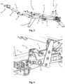
Figure 1 is a perspective view of a preferred embodiment of the support frame mechanism iin object, in a completely open configuration (relaxation, TV, etc.); -
Figure 2 represents the mechanism ofFigure 1 , in a front view; -
Figure 3 is another front view of the same mechanism asFigure 1 , but with some optional parts removed for clarity; and -
Figure 4 is an enlarged perspective view of a technical detail of the support frame mechanism in question. - With particular reference to
Figure 1 , M globally indicates a support frame mechanism for a seat K of an upholstered piece of furniture, such as an armchair, chair, sofa or the like, having reclining parts such as for example footrests and backrests, and furniture from a closed configuration erected to an open configuration extended or resting, for example relaxation or TV configuration. - The mechanism M comprises a quadrangular structure S substantially defined by two opposite main spars, 1 front and 2 rear, of the structure S itself, and two opposite lateral jaws, 3 left and 4 right, of the structure S itself.
- The structure S is adapted to form, directly integrated with the
jaws 3 and 4, a stable box Z for fixing the aforementioned seat K (not illustrated) of the upholstered furniture, and is equipped, at the opposite ends of theside jaws 3 and 4, withelements 5, 5' 5" and 5‴ suitable for defining feet and supporting the ground of the structure S itself, and also with at least one transverse AT rod. - According to what is better illustrated in
Figures 1 and3 , eachjaw 3,4 supports a relative actuating member O,O' (inFigure 1 and3 only O') for example a gas cylinder, or a worm screw or the like. -
Support members 8,8' of a backrest (known and not illustrated) are also provided mounted on saidside jaws 3 and 4, at saidrear spar 2 of the structure S itself. - According to what is better illustrated in
Figures 2 and3 , eachlateral jaw 3,4 comprises and is globally defined by aplate 9,9' to whicharms 10,10' are connected fulcrum to each other to form, together, an articulated quadrilateral QA adapted to move anassembly 11,11' of front rod elements, connected directly synchronised to the aforementioned seat K, as will be better explained below. - In particular, each
assembly 11,11' comprises agroup 12,12' of levers or arms B,B' suitably fulcrumized with each other to support a footrest/footboard element (known and not illustrated) to then define the portion of the mechanism M openable towards the aforementioned open configuration extended or at rest, for example relaxation or TV configuration, under the thrust of the aforementioned actuator member. - These arms B of each
group 12,12' are, preferably, designed to be covered closed by a special double casing C, C', specially faired, as illustrated inFigure 2 , thus improving the compactness and functionality of the entire mechanism M. - The characterization C,C is however optional and can also be omitted, as can be seen in
Figure 3 . - According to what is better illustrated in
Figure 4 on an enlarged scale, the directly synchronised connection of the arms B of eachset 11,11' of arms B to the aforementioned seat K takes place by means of aroller 13,13', equipped with an appropriate bearing, adapted to move sliding in contact with the specially shaped cam profile of therelative arm 10,10' which defines eachjaw 3,4. - In this way, in use, when the aforementioned actuator is actuated, the arms B,B' that support the footrest element are opened towards the open locked configuration extended (relaxation, TV), then in succession the consequent forward sliding movement of the seat K. The arms B can only return to their closed configuration when the action of returning the seat K to its normal retracted position is commanded.
- It should be noted that to simplify the mechanics of each side of the aforementioned structure S, all the levers for the advancement of the seat have been eliminated, replacing them with a linear recirculation guide of balls with the possibility of advancing the seat more than a mechanics with fixed stroke levers.
- In addition, the forward movement of the seat K is linked to the inclination of the backrest of the upholstered furniture, and with a greater stroke you can reach up to 180° to reach the "Bed" position.
Claims (5)
- A support frame mechanism (M) for a seat (K) of an upholstered piece of furniture, comprising a quadrangular box support structure (Z) of said seat (K), said structure (S) being substantially defined by transverse longitudinal means (1,2) and lateral jaw means (3,4), and by elements (5,5',5",5‴) adapted to define support feet of said structure (S), said elements (5,5',5",5‴) being mounted on said lateral jaw means (3,4;); said lateral jaw means (3,4) comprising plate means (9,9') and arm means (10,10') fulcrumed together and mounted on said plate means (9,9') to form an articulated quadrilateral (QA,QA') adapted to move a set (11,11') of rod-extendable elements, said arm means (10,10') being provided with a curved profile on which means (13,13') the roller of said structure are adapted to slide in contact.
- Mechanism according to claim 1, characterized in that said assembly (11,11') comprises a group (12,12') of arms (B,B') fulcrum between them.
- Mechanism according to claim 2, characterized in that said group (12,12') of arms (B,B') is provided with fairing cover casing means (C,C').
- Mechanism according to one or more of the preceding claims from 1 to 3, characterized in that said structure (S) is further provided with at least one transversal rod (AT).
- Mechanism according to one or more of the preceding claims from 1 to 4, characterized in that said jaw means (3,4) support actuating members (O,O').
Applications Claiming Priority (1)
| Application Number | Priority Date | Filing Date | Title |
|---|---|---|---|
| IT202300018511 | 2023-05-05 |
Publications (1)
| Publication Number | Publication Date |
|---|---|
| EP4458213A1 true EP4458213A1 (en) | 2024-11-06 |
Family
ID=90971617
Family Applications (1)
| Application Number | Title | Priority Date | Filing Date |
|---|---|---|---|
| EP24173842.6A Withdrawn EP4458213A1 (en) | 2023-05-05 | 2024-05-02 | Support frame mechanism for an upholstered furniture seat |
Country Status (1)
| Country | Link |
|---|---|
| EP (1) | EP4458213A1 (en) |
Citations (2)
| Publication number | Priority date | Publication date | Assignee | Title |
|---|---|---|---|---|
| US3813150A (en) * | 1972-08-22 | 1974-05-28 | Moharcs Ind Inc | Chair with backrest movable up and down and hardware therefor |
| WO2014180629A1 (en) * | 2013-05-10 | 2014-11-13 | Kintec-Solution Gmbh | Piece of seating furniture and fitting therefor |
-
2024
- 2024-05-02 EP EP24173842.6A patent/EP4458213A1/en not_active Withdrawn
Patent Citations (2)
| Publication number | Priority date | Publication date | Assignee | Title |
|---|---|---|---|---|
| US3813150A (en) * | 1972-08-22 | 1974-05-28 | Moharcs Ind Inc | Chair with backrest movable up and down and hardware therefor |
| WO2014180629A1 (en) * | 2013-05-10 | 2014-11-13 | Kintec-Solution Gmbh | Piece of seating furniture and fitting therefor |
Similar Documents
| Publication | Publication Date | Title |
|---|---|---|
| US10729251B2 (en) | Linkage mechanism for hi-leg seating unit | |
| US9844269B2 (en) | Motorized linkage mechanism for hi-leg seating unit | |
| CN106263778B (en) | Mechanical extending device and seat unit including the mechanical extending device | |
| US5169208A (en) | Chaise lounge recliner chair | |
| CN105208896B (en) | Rocker recliner mechanism with changeable characteristics | |
| US8398165B2 (en) | Powered rocker recliner linkage mechanism | |
| CN102133005B (en) | Power waves and slippage chaise longue link gear | |
| US10021980B2 (en) | Zero-wall clearance linkage mechanism with power seat drive | |
| US9603452B2 (en) | Gliding-reclining seating unit with power actuators | |
| US20240122346A1 (en) | Reclining seating unit with operatively-linked power actuators | |
| US20090174251A1 (en) | Zero-wall clearance linkage mechanism for a high-leg seating unit | |
| CN101484045A (en) | Linkage mechanism for a reclining chair | |
| CN105520409A (en) | Profile ottoman linkage | |
| CN106073249B (en) | Anti-toppling double-motor couch | |
| US7373675B2 (en) | Convertible sofa bed | |
| CN104856478A (en) | Chair and electro-mechanical stretching apparatus thereof | |
| US2774412A (en) | Reclining chair with extensible sectional leg rest | |
| CN112293997B (en) | Power stretching device | |
| EP3361907B1 (en) | Motorized linkage mechanism for hi-leg seating unit | |
| US3039815A (en) | Reclining chair of the multiple type | |
| CN101208029A (en) | synchronization mechanism | |
| IT202300001851U1 (en) | SUPPORT FRAME MECHANISM FOR A SEAT OF UPHOLSTERED FURNITURE.” | |
| US2663358A (en) | Article of repose for supporting the body of a person | |
| EP4166042A1 (en) | Moving mechanism | |
| EP4302653A1 (en) | Improved structure for a relax armchair |
Legal Events
| Date | Code | Title | Description |
|---|---|---|---|
| PUAI | Public reference made under article 153(3) epc to a published international application that has entered the european phase |
Free format text: ORIGINAL CODE: 0009012 |
|
| STAA | Information on the status of an ep patent application or granted ep patent |
Free format text: STATUS: THE APPLICATION HAS BEEN PUBLISHED |
|
| AK | Designated contracting states |
Kind code of ref document: A1 Designated state(s): AL AT BE BG CH CY CZ DE DK EE ES FI FR GB GR HR HU IE IS IT LI LT LU LV MC ME MK MT NL NO PL PT RO RS SE SI SK SM TR |
|
| 110E | Request filed for conversion into a national patent application [according to art. 135 epc] |
Effective date: 20250722 |
|
| STAA | Information on the status of an ep patent application or granted ep patent |
Free format text: STATUS: THE APPLICATION IS DEEMED TO BE WITHDRAWN |
|
| 18D | Application deemed to be withdrawn |
Effective date: 20250507 |