EP4458177A1 - Electronic atomisation device, atomiser, and assembly method for atomiser - Google Patents
Electronic atomisation device, atomiser, and assembly method for atomiser Download PDFInfo
- Publication number
- EP4458177A1 EP4458177A1 EP21969604.4A EP21969604A EP4458177A1 EP 4458177 A1 EP4458177 A1 EP 4458177A1 EP 21969604 A EP21969604 A EP 21969604A EP 4458177 A1 EP4458177 A1 EP 4458177A1
- Authority
- EP
- European Patent Office
- Prior art keywords
- atomization
- atomizer
- cores
- support member
- mounting
- Prior art date
- Legal status (The legal status is an assumption and is not a legal conclusion. Google has not performed a legal analysis and makes no representation as to the accuracy of the status listed.)
- Granted
Links
Images



Classifications
-
- A—HUMAN NECESSITIES
- A24—TOBACCO; CIGARS; CIGARETTES; SIMULATED SMOKING DEVICES; SMOKERS' REQUISITES
- A24F—SMOKERS' REQUISITES; MATCH BOXES; SIMULATED SMOKING DEVICES
- A24F40/00—Electrically operated smoking devices; Component parts thereof; Manufacture thereof; Maintenance or testing thereof; Charging means specially adapted therefor
- A24F40/40—Constructional details, e.g. connection of cartridges and battery parts
-
- A—HUMAN NECESSITIES
- A24—TOBACCO; CIGARS; CIGARETTES; SIMULATED SMOKING DEVICES; SMOKERS' REQUISITES
- A24F—SMOKERS' REQUISITES; MATCH BOXES; SIMULATED SMOKING DEVICES
- A24F40/00—Electrically operated smoking devices; Component parts thereof; Manufacture thereof; Maintenance or testing thereof; Charging means specially adapted therefor
- A24F40/40—Constructional details, e.g. connection of cartridges and battery parts
- A24F40/46—Shape or structure of electric heating means
-
- A—HUMAN NECESSITIES
- A24—TOBACCO; CIGARS; CIGARETTES; SIMULATED SMOKING DEVICES; SMOKERS' REQUISITES
- A24F—SMOKERS' REQUISITES; MATCH BOXES; SIMULATED SMOKING DEVICES
- A24F40/00—Electrically operated smoking devices; Component parts thereof; Manufacture thereof; Maintenance or testing thereof; Charging means specially adapted therefor
- A24F40/40—Constructional details, e.g. connection of cartridges and battery parts
- A24F40/48—Fluid transfer means, e.g. pumps
- A24F40/485—Valves; Apertures
-
- A—HUMAN NECESSITIES
- A24—TOBACCO; CIGARS; CIGARETTES; SIMULATED SMOKING DEVICES; SMOKERS' REQUISITES
- A24F—SMOKERS' REQUISITES; MATCH BOXES; SIMULATED SMOKING DEVICES
- A24F47/00—Smokers' requisites not otherwise provided for
-
- A—HUMAN NECESSITIES
- A24—TOBACCO; CIGARS; CIGARETTES; SIMULATED SMOKING DEVICES; SMOKERS' REQUISITES
- A24F—SMOKERS' REQUISITES; MATCH BOXES; SIMULATED SMOKING DEVICES
- A24F40/00—Electrically operated smoking devices; Component parts thereof; Manufacture thereof; Maintenance or testing thereof; Charging means specially adapted therefor
- A24F40/10—Devices using liquid inhalable precursors
Definitions
- This application relates to the technical field of electronic atomizers, and in particular, to an electronic atomization device, an atomizer and an assembly method for an atomizer.
- an electronic atomization device is mainly composed of an atomizer and a power supply assembly.
- the atomizer generally includes a liquid storage cavity and an atomization assembly.
- the liquid storage cavity is used for storing a substance to be atomized.
- the atomization assembly is used for heating and atomizing the substance to be atomized, to form an aerosol for an inhaler to inhale.
- the power supply assembly is used for supplying power to the atomizer.
- a single heating element is provided, and the generated aerosol is easily in contact with the side wall of an atomization cavity opposite to an atomization surface of an atomization core, resulting in reduced atomization efficiency and poor user experience.
- the main technical problem to be solved by this application is to provide an electronic atomization device, an atomizer and an assembly method for an atomizer, which solves the problems that the atomization efficiency of a single heating element is low and the aerosol is easily in contact with the side wall of the atomization cavity opposite to the atomization surface in the existing technology.
- An atomizer which includes: an airflow channel configured to deliver an aerosol; and two atomization cores provided in the airflow channel.
- Each of the two atomization cores includes an atomization surface, and the atomization surfaces of the two atomization cores are provided oppositely.
- the atomization surfaces of the two atomization cores are not perpendicular to the central axis of the atomizer.
- the atomizer further includes a support member provided between the two atomization cores, and the two side surfaces of the support member respectively hold the two atomization cores.
- the atomization surfaces of the two atomization cores are inclined relative to the central axis of the atomizer, and the distance between the atomization surfaces of the two atomization cores gradually decreases along the airflow direction in the airflow channel; and the two opposite side surfaces of the support member include inclined surfaces respectively matched with the atomization surfaces of the two atomization cores.
- the included angle between the atomization surfaces of the atomization cores and the central axis of the atomizer is ⁇ , where 0° ⁇ ⁇ 20°.
- the support member includes of a wedge-shaped structure, and the two atomization cores are respectively and fixedly connected with the two opposite side surfaces of the wedge-shaped structure.
- the two opposite side surfaces of the support member are respectively and fixedly connected with the edges of the atomization surfaces of the two atomization cores.
- the atomizer further includes a mounting base.
- the mounting base includes a base body and the support member connected with the side of the base body facing toward the atomization cores.
- the atomizer further includes a mounting top cover, and the mounting top cover is matched with the base body to form a mounting cavity.
- the mounting cavity is a part of the airflow channel.
- the two atomization cores and the support member are provided in the mounting cavity, and the two atomization cores are clamped between the mounting top cover and the side surfaces of the support member.
- each of the tow atomization cores includes a liquid guiding substrate, a heating element and electrodes.
- the liquid guiding substrate includes the atomization surface and a liquid absorbing surface opposite to the atomization surface.
- the heating element and the electrodes are provided on the atomization surface and connected with each other.
- the liquid guiding substrate includes a dense substrate.
- the atomization surface includes an atomization region and a non-atomization region surrounding the atomization region.
- the dense substrate includes a micropore array region, and the micropore array region includes a plurality of micropores configured to guide a substance to be atomized from the liquid absorbing surface to the atomization surface.
- the micropore array region of the atomization surface includes the atomization region of the atomization surface.
- the heating element is provided in the atomization region, and the electrodes are provided in the non-atomization region.
- the atomizer further includes electrode connectors, one ends of the electrode connectors are provided on the base body, and the other ends of the electrode connectors are abutted against the electrodes.
- the electrode connectors include ejector pins, and the end surfaces of the ejector pins abutted against the electrodes include inclined surfaces parallel to the atomization surface.
- the electrode connectors include elastic pieces, and the parts of the elastic pieces abutted against the electrodes are bent into curved surfaces.
- the atomizer further includes a seal member, and the seal member wraps the edges of the atomization cores, partial atomization surfaces and partial liquid absorbing surfaces of the atomization cores are exposed from the seal member.
- the support member holds the atomization cores through the seal member.
- An electronic atomization device which includes an atomizer and a power supply assembly.
- the atomizer is the atomizer described above, and the power supply assembly supplies power to the atomizer.
- An assembly method for an atomizer includes: providing a mounting top cover in a housing, where a mounting space is formed between the two opposite side walls of the mounting top cover; fixing two atomization cores on the two side surfaces of a support member respectively, where the two side surfaces of the support member are respectively parallel to the inner surfaces of the two opposite side walls of the mounting top cover; and pushing the support member provided with the two atomization cores into the mounting space, enabling each of the two atomization cores to be clamped between the side surface of the support member and the side wall of the mounting top cover.
- the support member includes a wedge-shaped structure; and the fixing two atomization cores on the two side surfaces of a support member respectively includes: fixing the two atomization cores on the two opposite side surfaces of the wedge-shaped structure respectively.
- the method before the fixing two atomization cores on the two side surfaces of a support member respectively , the method further includes: providing a mounting base, where the mounting base includes a base body and the support member connected with the base body; before the pushing the support member provided with the two atomization cores into the mounting space, the method further includes: providing one ends of electrode connectors on the base body; and the pushing the support member provided with the two atomization cores into the mounting space further includes: abutting the other ends of the electrode connectors against electrodes of the atomization cores.
- the atomizer includes: the airflow channel configured to deliver an aerosol; and two atomization cores provided in the airflow channel.
- Each of the two atomization cores includes an atomization surface, and the atomization surfaces of the two atomization cores are provided oppositely. The atomization surfaces of the two atomization cores are not perpendicular to the central axis of the atomizer.
- the atomization efficiency is improved; and by providing the atomization surfaces of the two atomization cores oppositely, the aerosol generated through atomization by the atomization cores is prevented from contacting and colliding with the side wall of the atomization cavity opposite to the atomization surfaces, the liquefaction of the aerosol is reduced, and the atomization efficiency is further improved.
- first”, “second”, and “third” are merely intended for a purpose of description, and shall not be understood as indicating or implying relative importance or implicitly indicating the number of indicated technical features. Therefore, features defined by “first”, “second”, and “third” may explicitly or implicitly include at least one of the features.
- the term “multiple” means at least two, such as two or three, unless otherwise specifically defined. All directional indications (for example, up, down, left, right, front, back%) in the embodiments of this application are only used for explaining relative position relationships, movement situations, or the like between various components in a specific posture (as illustrated in the drawings). If the specific posture changes, the directional indications change accordingly.
- a process, method, system, product, or device that includes a series of steps or units is not limited to the listed steps or units; and instead, further optionally includes a step or unit that is not listed, or further optionally includes another step or unit that is intrinsic to the process, method, product, or device.
- FIG. 1 illustrates a schematic structural diagram of an electronic atomization device according to this application.
- This embodiment provides an electronic atomization device 100.
- the electronic atomization device 100 may be used for atomizing a substance to be atomized.
- the electronic atomization device 100 includes an atomizer 101 and a power supply assembly 102 connected with each other.
- the atomizer 101 is used for storing the substance to be atomized, and atomizing the substance to be atomized to form an aerosol that may be inhaled by a user.
- the substance to be atomized may be a liquid substrate such as liquid medicine and plant leaf liquid.
- the atomizer 101 may be used in different fields such as medicine, cosmetics and electronic aerosolization.
- the power supply assembly 102 includes a battery, an airflow sensor (not shown), a controller (not shown), etc.
- the power supply assembly 102 is used for supplying power to the atomizer 101 and controlling the atomizer 101 to work, enabling the atomizer 101 to atomize the substance to be atomized to form the aerosol.
- the airflow sensor is used for detecting an airflow change in the electronic atomization device 100, and the controller activates the electronic atomization device 100 according to the airflow change detected by the airflow sensor.
- the atomizer 101 and the power supply assembly 102 may be integrally provided or detachably connected according to specific needs.
- the electronic atomization device 100 further includes other components such as a microphone and a holder in the existing electronic atomization device 100. Specific structures and functions of these components are the same as or similar to those in the existing technology. For details, a reference may be made to the existing technology, which will not be repeated here.
- FIG. 2 illustrates a longitudinal sectional schematic structural diagram of an atomizer in an electronic atomization device according to this application.
- FIG. 3 illustrates a partial enlarged diagram of the atomizer in FIG. 2 .
- the atomizer 101 includes a housing 1, a mounting seat 3, atomization cores 2, a first seal member 6, a second seal member 7, electrode connectors 5, and a suction nozzle 8.
- the housing 1 is provided with a mounting space 14.
- the mounting seat 3 is accommodated in the mounting space 14, and is fixedly connected with the inner side surface of the mounting space 14 through the first seal member 6.
- the mounting seat 3 is matched with the inner wall surface of part of the mounting space 14 to form a liquid storage cavity 15.
- the liquid storage cavity 15 is used for storing the substance to be atomized.
- the mounting seat 3 is provided with a mounting cavity 33.
- the atomization cores 2 are accommodated in the mounting cavity 33.
- the atomization cores 2 are fixedly connected with the mounting seat 3 through the second seal member 7.
- the suction nozzle 8 is provided at the end of the housing 1 away from the mounting seat 3.
- the suction nozzle 8 sleeves the end of the housing 1.
- the suction nozzle 8 is provided with an air suction hole 81.
- the air suction hole 81 is used for delivering the aerosol generated by the atomizer 101 to the mouth of the user.
- the housing 1 includes a first annular side wall 11 and a first top wall 12 connected with one end of the first annular side wall 11.
- the first annular side wall 11 and the first top wall 12 are matched to form the mounting space 14.
- the end of the mounting space 14 away from the first top wall 12 is open.
- the first top wall 12 is provided with an air outlet hole 121.
- the edge of the air outlet hole 121 extends into the mounting space 14 to form an air guiding channel 13.
- the air guiding channel 13 is integrally formed with the housing 1.
- the cross section of the mounting space 14 may be elliptical or rectangular. In other words, the cross section of the mounting space 14 has a length direction and a width direction. In other embodiments, the cross section of the mounting space 14 may be circular.
- FIG. 4 illustrates a schematic structural diagram of an embodiment of an atomization core according to this application.
- the atomization core 2 includes a liquid guiding substrate, a heating element 23 and electrodes 24.
- the heating element 23 and the electrodes 24 are provided on an atomization surface 25 and connected with each other.
- the liquid guiding substrate includes a dense substrate 22.
- the dense substrate 22 includes the atomization surface 25 and a liquid absorbing surface 26 opposite to the atomization surface 25.
- the liquid absorbing surface 26 directly contacts the substance to be atomized in the liquid storage cavity 15.
- the atomization surface 25 is used for atomizing the substance to be atomized to obtain the aerosol.
- the dense substrate 22 includes a micropore array region.
- the micropore array region includes a plurality of micropores for guiding the substance to be atomized from the liquid absorbing surface 26 to the atomization surface 25.
- the micropore array region of the atomization surface 25 includes an atomization region 253 of the atomization surface 25.
- a region outside the micropore array region of the atomization surface 25 is a non-atomization region 254 of the atomization surface 25.
- the non-atomization region 254 is provided around the atomization region 253.
- the heating element 23 is provided in the atomization region 253.
- the electrodes 24 are provided in the non-atomization region 254.
- the dense substrate 22 includes a glass substrate, and may also include a dense ceramic substrate.
- each atomization core 2 includes a porous ceramic substrate and the heating element 23.
- the porous ceramic substrate includes the atomization surface 25 and the liquid absorbing surface 26 opposite to the atomization surface 25.
- the heating element 23 is provided on the atomization surface 25.
- the entire atomization surface 25 of the heating element 23 is the atomization region 253.
- the number of the atomization cores 2 is more than one.
- the atomization surfaces 25 of the multiple atomization cores 2 are provided oppositely.
- the atomization surfaces 25 of the atomization cores 2 are not perpendicular to the central axis of the atomizer 101.
- the atomization surface 25 of each atomization core 2 is inclined relative to the central axis of the atomizer 101, and the distance between the atomization surfaces 25 of the multiple atomization cores 2 gradually decreases along the airflow direction in the airflow channel 43, i.e., the direction from the bottom of the atomizer 101 to the air suction hole 81.
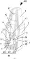
- FIG. 5 illustrates a structural diagram of a first embodiment of an atomizer according to this application.
- FIG. 6 illustrates a schematic exploded diagram of an embodiment of an atomizer according to this application.
- the number of the atomization cores 2 is two.
- the two atomization cores 2 include a first atomization core 201 and a second atomization core 202.
- the first atomization core 201 includes a first atomization surface 251 and a first liquid absorbing surface 261 opposite to each other.
- the second atomization core 202 includes a second atomization surface 252 and a second liquid absorbing surface 262 opposite to each other.
- the first atomization surface 251 and the second atomization surface 252 are provided oppositely. Both the first atomization surface 251 and the second atomization surface 252 are not perpendicular to the central axis L of the atomizer 101.
- the first atomization surface 251 of the first atomization core 201 and the second atomization surface 252 of the second atomization core 202 are inclined relative to the central axis L of the atomizer 101, and the distance between the first atomization surface 251 and the second atomization surface 252 gradually decreases along the airflow direction of the airflow channel 43.
- the included angle between the first atomization surface 251 of the first atomization core 201/the second atomization surface 252 of the second atomization core 202 and the central axis L of the atomizer 101 is ⁇ , where 0° ⁇ ⁇ 20°, as illustrated in FIG. 5 .
- the included angle ⁇ between the first atomization surface 251/the second atomization surface 252 and the central axis L of the atomizer 101 is 16°.
- the first atomization core 201 and the second atomization core 202 may be the same or different, which is not limited here. In another embodiment, the number of the atomization cores 2 may also be three, four, etc.
- the mounting seat 3 is mounted at the part of the mounting space 14 away from the first top wall 12.
- the mounting seat 3 includes a mounting top cover 31 and a mounting base 32.
- the mounting top cover 31 and the mounting base 32 are matched with each other.
- the mounting base 32 is provided on the side of the mounting top cover 31 away from the first top wall 12.
- the mounting top cover 31 is fixedly connected with part of the inner side wall of the mounting space 14.
- the part of the inner side wall of the mounting space 14 close to the first top wall 12 is matched with the outer wall of the mounting top cover 31 to form the liquid storage cavity 15.
- the liquid storage cavity 15 surrounds the periphery of the air guiding channel 13.
- the mounting top cover 31 and the mounting base 32 are matched to form the mounting cavity 33.
- the mounting cavity 33 is used for accommodating the atomization cores 2.
- the mounting top cover 31 is provided with a liquid flowing hole 313 and a vent hole 314.
- the liquid flowing hole 313 and the vent hole 314 are spaced apart.
- the number of the liquid flowing holes 313 is the same as the number of the atomization cores 2, and the multiple liquid flowing holes 313 are spaced apart.
- two liquid flowing holes 313 are provided.
- the two liquid flowing holes 313 include a first liquid flowing hole 3131 and a second liquid flowing hole 3132.
- the first liquid flowing hole 3131 and the second liquid flowing hole 3132 are spaced apart and opposite to each other, enabling the first atomization core 201 to cover the first liquid flowing hole 3131, and the first liquid absorbing surface 261 of the first atomization core 201 opposite to the first atomization surface 251 to face toward the liquid storage cavity 15; and enabling the second atomization core 202 to cover the second liquid flowing hole 3132, and the second liquid absorbing surface 262 of the first atomization core 201 opposite to the second atomization surface 252 to face toward the liquid storage cavity 15, thus making the first atomization surface 251 of the first atomization core 201 opposite to the second atomization surface 252 of the second atomization core 202.
- the end of the air guiding channel 13 away from the air outlet hole 121 is connected with the vent hole 314.
- the end of the air guiding channel 13 close to the air outlet hole 121 is communicated with the air suction hole 81.
- the end of the air guiding channel 13 away from the air outlet hole 121 is hermetically communicated with the vent hole 314 through the first seal member 6 to avoid air leakage between the air guiding channel 13 and the vent hole 314 of the mounting top cover 31.
- the air guiding channel 13 is communicated with the mounting cavity 33 through the vent hole 314.
- the atomization core 2 covers the liquid flowing hole 313, and the periphery of the atomization core 2 is in close fit with the inner wall surface of the liquid flowing hole 313 through the second seal member 7, so as to avoid the leakage of the substance to be atomized in the liquid storage cavity 15.
- the two second seal members 7 include a first seal ring 71 and a second seal ring 72.
- the end surfaces of the first seal ring 71 and the second seal ring 72 away from the liquid storage cavity 15 are respectively provided with grooves.
- the first atomization core 201 is embedded in the groove of the first seal ring 71, and the second atomization core 202 is embedded in the groove of the second seal ring 72.
- first atomization surface 251 of the first atomization core 201 is in the same plane as the end surface of the first seal ring 71 away from the liquid storage cavity 15; and the second atomization surface 252 of the second atomization core 202 is in the same plane as the end surface of the second seal ring 72 away from the liquid storage cavity 15.
- FIG. 7 illustrates a schematic structural diagram of an embodiment of a mounting top cover according to this application.
- FIG. 8 illustrates a schematic structural diagram of an embodiment of a mounting base according to this application.
- the mounting top cover 31 includes a second annular side wall 311 and a second top wall 312 connected with one end of the second annular side wall 311.
- the vent hole 314 is provided in the second top wall 312, and the liquid flowing hole 313 is provided in the second annular side wall 311, as illustrated in FIG. 7 .
- the first liquid flowing hole 3131 and the second liquid flowing hole 3132 are provided in the second annular side wall 311, and are respectively provided at opposite positions of the second annular side wall 311.
- the mounting base 32 includes a base body 321 and a support member 328 connected with the side of the base body 321 facing toward the atomization core 2.
- the support member 328 is perpendicular to the surface of the base body 321 on which the support member 328 is provided.
- a connection portion is provided on the base body 321.
- the base body 321 is clamped with the mounting top cover 31 through the connection portion, enabling the mounting base 32 and the mounting top cover 31 to be matched to form the mounting cavity 33.
- the first atomization surface 251 of the first atomization core 201 and the second atomization surface 252 of the second atomization core 202 are matched with the inner wall surface of the mounting cavity 33 to form an atomization cavity 4.
- the surface of the base body 321 on which the support member 328 is provided is used as the bottom wall of the atomization cavity 4.
- the atomization cavity 4 includes an air inlet channel 41 and an air outlet channel 42.
- the first atomization core 201 and the second atomization core 202 each have a first end 211 and a second end 212 opposite to each other.
- the first end 211 of the first atomization core 201 and the first end 211 of the second atomization core 202 are provided close to the air inlet channel 41 of the atomization cavity 4.
- the second end 212 of the second atomization core 202 and the second end 212 of the second atomization core 202 are provided close to the air outlet channel 42 of the atomization cavity 4.
- the first end 211 of the first atomization core 201 and the first end 211 of the second atomization core 202 are provided close to the base body 321.
- the air inlet channel 41 of the atomization cavity 4 is provided on the base body 321.
- the air outlet channel 42 of the atomization cavity 4 is provided opposite to the base body 321.
- the air inlet channel 41, the atomization cavity 4, the air outlet channel 42, and the air guiding channel 13 are matched to form the airflow channel 43.
- the airflow channel 43 is used for delivering the aerosol to the mouth of the user.
- the air inlet channel 41 includes a first air inlet channel 411, a second air inlet channel 412 and a central air inlet channel 413 that are spaced apart.
- the first air inlet channel 411 is provided corresponding to the first atomization core 201.
- the airflow of the first air inlet channel 411 is delivered from the end of the first atomization surface 251 close to the first air inlet channel 411 to the end away from the first air inlet channel 411 to carry the aerosol. That is, the airflow of the first air inlet channel 411 is delivered from the first end 211 of the first atomization core 201 to the second end 212 of the first atomization core 201.
- the second air inlet channel 412 is provided corresponding to the second atomization core 202.
- the airflow of the second air inlet channel 412 is delivered from the end of the second atomization surface 252 close to the second air inlet channel 412 to the end of the second atomization surface 252 away from the second air inlet channel 412 to carry the aerosol. That is, the airflow of the second air inlet channel 412 is delivered from the first end 211 of the second atomization core 202 to the second end 212 of the second atomization core 202.
- the central air inlet channel 413 is provided between the first air inlet channel 411 and the second air inlet channel 412, and the central air inlet channel 413 delivers the airflow from the end of the first atomization surface 251 close to the first air inlet channel 411 to the end of the first atomization surface 251 away from the first air inlet channel 411. That is, the airflow of the central air inlet channel 413 may carry the aerosol trapped in the low-pressure region between the first air inlet channel 411 and the second air inlet channel 412 to the air outlet channel 42 of the atomization cavity 4, thus improving the delivery efficiency of the aerosol and strengthening the mixing of the aerosol and air.
- the airflow direction of the central air inlet channel 413 is parallel to the central axis of the atomizer 101.
- the first air inlet channel 411 and the second air inlet channel 412 are symmetrically provided.
- the central air inlet channel 413 is located on the symmetrical plane between the first air inlet channel 411 and the second air inlet channel 412.
- the central air inlet channel 413 is provided in the projection region of the air outlet channel 42 on the bottom wall.
- the central axis of the central air inlet channel 413 coincides with the central axis of the air outlet channel 42 of the atomization cavity 4.
- the central air inlet channel 413 is provided on the plane where the central axis of the atomizer 101 is located, and the plane where the central axis of the atomizer 101 is located passes through the central axis of support member 328.
- the central air inlet channel 413 is provided on the base body 321, and the central axis of the central air inlet channel 413 is perpendicular to the base body 321.
- the end surface of the first air inlet channel 411 close to the first atomization core 201 is not higher than the first end 211 of the first atomization core 201. Moreover, the end surface of the first air inlet channel 411 close to the first atomization core 201 is not higher than the end of the atomization region 253 of the first atomization surface 251 close to the first end 211 of the first atomization core 201. The end surface of the second air inlet channel 412 close to the second atomization core 202 is not higher than the first end 211 of the second atomization core 202.
- the end surface of the second air inlet channel 412 close to the second atomization core 202 is not higher than the end of the atomization region 253 of the second atomization surface 252 close to the first end 211 of the second atomization core 202.
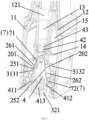
- FIG. 9 illustrates a structural diagram of a second embodiment of an atomizer according to this application.
- FIG. 10 illustrates a sectional top view at the position A-A in FIG. 9 .
- FIG. 11 illustrates a structural diagram of a third embodiment of an atomizer according to this application.
- the edge of the port of the first air inlet channel 411 close to the first atomization core 201 is a straight line and coplanar with the first atomization surface 251.
- the edge of the port of the second air inlet channel 412 close to the second atomization core 202 is a straight line and coplanar with the second atomization surface 252.
- the inner side surface of the first air inlet channel 411 close to the first atomization core 201 is a flat surface and coplanar with the first atomization surface 251.
- the inner side surface of the second air inlet channel 412 close to the second atomization core 202 is a flat surface and coplanar with the second atomization surface 252.
- the first atomization surface 251 of the first atomization core 201 and the second atomization surface 252 of the second atomization core 202 are both parallel to the central axis of the atomizer 101.
- the central axis of the first air inlet channel 411 and the central axis of the second air inlet channel 412 are perpendicular to the mounting base 32, that is, the central axis of the first air inlet channel 411 and the central axis of the second air inlet channel 412 are both parallel to the central axis of the central air inlet channel 413.
- the first end 211 of the first atomization core 201 is abutted against the end surface of the first air inlet channel 411 close to the first atomization core 201 through the first seal ring 71.
- the inner side surface of the first air inlet channel 411 close to the first atomization surface 251 is a flat surface and coplanar with the first atomization surface 251.
- the first end 211 of the second atomization core 202 is abutted against the end surface of the second air inlet channel 412 close to the second atomization core 202 through the second seal ring 72.
- the inner side surface of the second air inlet channel 412 close to the second atomization surface 252 is a flat surface and coplanar with the first atomization surface 251.
- the first atomization surface 251 of the first atomization core 201 and the second atomization surface 252 of the second atomization core 202 are both inclined relative to the central axis of the atomizer 101, and the central axis of the first air inlet channel 411 is parallel to the first atomization surface 251, that is, the central axis of the first air inlet channel 411 is inclined relative to the central axis of the central air inlet channel 413.
- the central axis of the second air inlet channel 412 is parallel to the second atomization surface 252, that is, the central axis of the second air inlet channel 412 is inclined relative to the central axis of the central air inlet channel 413.
- the first end 211 of the first atomization core 201 is abutted against the end surface of the first air inlet channel 411 close to the first atomization core 201 through the first seal ring 71.
- the inner side surface of the first air inlet channel 411 close to the first atomization surface 251 is a flat surface and coplanar with the first atomization surface 251.
- the first end 211 of the second atomization core 202 is abutted against the end surface of the second air inlet channel 412 close to the second atomization core 202 through the second seal ring 72.
- the inner side surface of the second air inlet channel 412 close to the second atomization surface 252 is a flat surface and coplanar with the first atomization surface 251.
- the first atomization surface 251 of the first atomization core 201 and the second atomization surface 252 of the second atomization core 202 are both inclined relative to the central axis of the atomizer 101.
- the central axis of the first air inlet channel 411 and the central axis of the second air inlet channel 412 are both parallel to the central axis of the central air inlet channel 413.
- the end of the inner side surface of the first air inlet channel 411 close to the first atomization surface 251 is abutted against the first end 211 of the first atomization core 201 through the first seal ring 71.
- the first atomization surface 251 of the first atomization core 201 is in flush with the surface of the first seal ring 71 close to the atomization cavity 4.
- the edge of the first seal ring 71 facing toward the atomization cavity 4 and close to the base body 321 is in close fit with the end of the inner side surface of the first air inlet channel 411 close to the first atomization core 201, that is, the end of the inner side surface of the first air inlet channel 411 close to the first atomization core 201 is coplanar with the first atomization surface 251.
- the end of the inner side surface of the second air inlet channel 412 close to the second atomization surface 252 is abutted against the first end 211 of the second atomization core 202 through the second seal ring 72.
- the second atomization surface 252 of the second atomization core 202 is in flush with the surface of the second seal ring 72 close to the atomization cavity 4.
- the edge of the second seal ring 72 facing toward the atomization cavity 4 and close to the base body 321 is in close fit with the end of the inner side surface of the second air inlet channel 412 close to the second atomization core 202, that is, the end of the inner side surface of the second air inlet channel 412 close to the second atomization core 202 is coplanar with the second atomization surface 252.
- the first air inlet channel 411, the second air inlet channel 412 and the central air inlet channel 413 are rectangular holes 325 with a rectangular cross section or multiple circular holes 326 with a circular cross section and perpendicular to the central axis of the atomizer 101.
- the first air inlet channel 411 and the second air inlet channel 412 are both rectangular holes 325 with a rectangular cross section and perpendicular to the central axis of the atomizer 101, and the length direction of the rectangular holes 325 is parallel to the atomization surface 25.
- the central air inlet channel 413 is multiple circular holes 326 with a circular cross section and perpendicular to the central axis of the atomizer 101.
- the multiple circular holes 326 are distributed along the length direction of the rectangular holes 325, and the length of the multiple circular holes 326 distributed along the length direction of the rectangular holes 325 is not less than the size of the length direction of the rectangular holes 325.
- the length of the rectangular holes 325 is 0.5-1 times the size of the atomization region 253 of the atomization surface 25 in the length direction of the rectangular holes 325.
- the width of the rectangular holes 325 is 0.3 mm-0.6 mm.
- the diameter of the circular holes 326 is 0.3 mm-0.6 mm.
- a first air inlet hole 322, a second air inlet hole 323, third air inlet holes 324 and mounting holes 327 spaced apart are provided in the base body 321.
- the first air inlet hole 322, the second air inlet hole 323, the third air inlet holes 324 and the mounting holes 327 all run through the base body 321.
- Four mounting holes 327 are provided, and the four mounting holes 327 are used for threading the electrode connectors 5.
- the first air inlet hole 322 is used as the first air inlet channel 411
- the second air inlet hole 323 is used as the second air inlet channel 412
- the third air inlet holes 324 are used as third air inlet channels 41.
- the third air inlet holes 324 are provided between the first air inlet hole 322 and the second air inlet hole 323.
- the first air inlet hole 322 and the second air inlet hole 323 are rectangular holes 325 with a rectangular cross section and perpendicular to the central axis of the atomizer 101.
- the length of the rectangular holes 325 is 2 mm and the width of the rectangular holes 325 is 0.4 mm.
- the third air inlet holes 324 are three circular holes 326 with a circular cross section and perpendicular to the central axis of the atomizer 101.
- the three circular holes 326 are distributed along the length direction of the rectangular holes 325.
- the diameter of the circular hole 326 is 0.4 mm. In other embodiments, the number of the circular holes 326 may also be four or five.
- the first air inlet channel is correspondingly provided for the first atomization core
- the second air inlet channel is correspondingly provided for the second atomization core.
- the airflow entering through the first air inlet channel carries the aerosol generated through atomization by the first atomization core
- the airflow entering through the second air inlet channel carries the aerosol generated through atomization by the second atomization core, thus improving the delivery efficiency of the aerosol.
- the airflow entering through the central air inlet channel may reduce the amount of the aerosol trapped in the low-pressure region between the first air inlet channel and the second air inlet channel, and may also enhance the mixing of the aerosol and the airflow, further improving the delivery efficiency of the aerosol.
- the support member 328 is provided on the base body 321.
- the support member 328 is provided between two adjacent atomization cores 2.
- the two side surfaces of the support member 328 are respectively abutted against the two atomization cores 2.
- the support member 328 may be of a triangular prism structure, rectangular structure, or wedge-shaped structure, or any other prism structure.
- the atomization cores 2 are parallel to the central axis of the atomizer 101.
- the support member 328 is of the wedge-shaped structure
- the atomization cores 2 are inclined relative to the central axis of the atomizer 101.
- the support member 328 is of the wedge-shaped structure, that is, the two opposite side surfaces of the support member 328 are inclined surfaces, and the support member 328 is of a symmetrical structure.
- the two opposite side surfaces of the support member 328 are inclined surfaces matched with the atomization surfaces 25 of the two atomization cores 2.
- the two opposite side surfaces of the support member 328 are respectively and fixedly connected with the edges of the atomization surfaces 25 of the two atomization cores 2.
- the first atomization core 201 and the second atomization core 202 are respectively abutted against the two opposite side surfaces of the support member 328.
- the edge of the first atomization surface 251 of the first atomization core 201 and the edge of the second atomization surface 252 of the second atomization core 202 are respectively abutted against the two opposite side surfaces of the support member 328.
- the first atomization core 201 and the support member 328 are sealed from each other through the first seal ring 71, and the second atomization core 202 and the support member 328 are sealed from each other through the second seal ring 72.
- Two support members 328 are provided. The two support members 328 are relatively parallel and spaced apart.
- the two sides of one support member 328 are respectively abutted against the edge of one side of the first atomization surface 251 and the edge of one side of the second atomization surface 252, and the two side surfaces of the other support member 328 are respectively abutted against the edge of the other side of the first atomization surface 251 and the edge of the other side of the second atomization surface 252.
- the atomization cores 2 and the support members 328 are accommodated in the mounting cavity 33, and the atomization cores 2 are clamped between the side wall of the mounting top cover 31 and the side surfaces of the support members 328.
- the cross-sectional area of the mounting cavity 33 gradually decreases along the direction of the mounting cavity 33 from the mounting base 32 to the mounting top cover 31.
- the longitudinal section of the mounting cavity 33 parallel to the support member 328 is trapezoidal.
- FIG. 12 illustrates a schematic assembly structural diagram of a first atomization core/second atomization core and an electrode connector during assembling according to this application.
- one electrode is illustrated for each atomization core.
- the atomizer 101 further includes electrode connectors 5, one ends of the electrode connectors 5 are provided on the base body 321, and the other ends of the electrode connectors 5 are abutted against the electrodes 24 on the atomization cores 2.
- the base body 321 is provided with mounting holes 327, and one ends of the electrode connectors 5 away from the electrodes 24 are provided in the mounting holes 327 in a penetrating manner.
- the electrode connectors 5 are made of a conductive material, which may be a metal material such as copper or aluminum, or a conductive polymer.
- the electrode connectors 5 are ejector pins 51, and the end surfaces of the ejector pins 51 abutted against the electrodes 24 are inclined surfaces parallel to the atomization surface 25.
- the electrode connectors 5 are elastic pieces 52, and the parts of the elastic pieces 52 abutted against the electrodes 24 are bent into curved surfaces.
- the atomizer in the electronic atomization device provided in this embodiment includes the airflow channel and two atomization cores.
- the airflow channel are used for delivering aerosol.
- the two atomization cores are provided in the airflow channel.
- Each atomization core includes an atomization surface, and the atomization surfaces of the two atomization cores are provided oppositely.
- the atomization surfaces of the atomization cores are not perpendicular to the central axis of the atomizer.
- the atomization efficiency is improved; and by providing the atomization surfaces of the two atomization cores oppositely, the aerosol generated through atomization by the atomization cores is prevented from contacting and colliding with the side wall of the atomization cavity opposite to the atomization surfaces, the liquefaction of the aerosol is reduced, and the atomization efficiency is further improved.
- FIG. 13 illustrates a flowchart of an assembly method for an atomizer according to this application.
- This embodiment provides an assembly method for an atomizer.
- the assembly method for the atomizer is used for implementing the assembling of the atomizer described in the embodiment above.
- the assembly method for the atomizer includes operations executed by the following blocks.
- a mounting top cover is provided in a housing.
- a mounting space is formed between the two opposite side walls of the mounting top cover.
- the mounting top cover is firstly mounted in the housing, the inner wall surface of the part of the mounting space close to the air outlet in the housing is matched with the mounting top cover to form a liquid storage cavity, the end of the air guiding channel of the housing away from the air outlet is inserted into the vent hole of the first seal member, and the vent hole in the mounting top cover is communicated with the air guiding channel in the housing.
- two atomization cores are fixed on the two side surfaces of a support member respectively.
- the two side surfaces of the support member are respectively parallel to the inner surfaces of the two opposite side walls of the mounting top cover.
- a first seal ring sleeves the periphery of a first atomization core, the first atomization surface of the first atomization core faces toward the mounting space, and the first atomization core sleeved with the first seal ring is mounted in a first liquid flowing hole.
- a second seal ring sleeves the periphery of a second atomization core, the second atomization surface of the second atomization core faces toward the mounting space, and the second atomization core sleeved with the second seal ring is mounted in a second liquid flowing hole.
- a mounting base is provided.
- the mounting base includes a base body and support members connected with the base body. Two support members are provided and the two support members are both of a wedge-shaped structure.
- the side of the mounting base provided with the support members are enabled faces toward the mounting space, and the connecting line between the two support members is perpendicular to the connecting line between the first atomization core and the second atomization core, so as to support the first atomization core and the second atomization core through the two side surfaces of the support members.
- electrode connectors need to be mounted on the base body, enabling the electrode connectors to be respectively connected with electrodes on the first atomization surface and electrodes on the second atomization core.
- the support member provided with the two atomization cores is pushed into the mounting space, enabling each of the two atomization cores to be clamped between the side surface of the support member and the side wall of the mounting top cover.
- the mounting base is pushed towards the direction close to the mounting top cover into the mounting space, and the two side surfaces of the support members are respectively in close fit with the first seal ring provided on the periphery of the first atomization core and the second seal ring provided on the periphery of the second atomization core, so as to support the first atomization core and the second atomization core.
- the electrode connectors are abutted against the electrodes on the atomization cores.
- the surfaces of the electrode connectors close to the electrodes are inclined surfaces parallel to the first atomization surface or the second atomization surface.
- the assembly method for the atomizer by providing the support members and supporting the first atomization core and the second atomization core through the two opposite side surfaces of the support members, the fixing of the first atomization core and the second atomization core is achieved, and the assembly method is simple and convenient to implement.
Landscapes
- Fuel-Injection Apparatus (AREA)
- Disinfection, Sterilisation Or Deodorisation Of Air (AREA)
Abstract
Description
- This application relates to the technical field of electronic atomizers, and in particular, to an electronic atomization device, an atomizer and an assembly method for an atomizer.
- In the existing technology, an electronic atomization device is mainly composed of an atomizer and a power supply assembly. The atomizer generally includes a liquid storage cavity and an atomization assembly. The liquid storage cavity is used for storing a substance to be atomized. The atomization assembly is used for heating and atomizing the substance to be atomized, to form an aerosol for an inhaler to inhale. The power supply assembly is used for supplying power to the atomizer. In the existing atomizer, a single heating element is provided, and the generated aerosol is easily in contact with the side wall of an atomization cavity opposite to an atomization surface of an atomization core, resulting in reduced atomization efficiency and poor user experience.
- The main technical problem to be solved by this application is to provide an electronic atomization device, an atomizer and an assembly method for an atomizer, which solves the problems that the atomization efficiency of a single heating element is low and the aerosol is easily in contact with the side wall of the atomization cavity opposite to the atomization surface in the existing technology.
- In order to resolve the above technical problem, a first technical solution adopted by this application is as follows. An atomizer is provided, which includes: an airflow channel configured to deliver an aerosol; and two atomization cores provided in the airflow channel. Each of the two atomization cores includes an atomization surface, and the atomization surfaces of the two atomization cores are provided oppositely. The atomization surfaces of the two atomization cores are not perpendicular to the central axis of the atomizer.
- In some embodiments, the atomizer further includes a support member provided between the two atomization cores, and the two side surfaces of the support member respectively hold the two atomization cores.
- In some embodiments, the atomization surfaces of the two atomization cores are inclined relative to the central axis of the atomizer, and the distance between the atomization surfaces of the two atomization cores gradually decreases along the airflow direction in the airflow channel; and the two opposite side surfaces of the support member include inclined surfaces respectively matched with the atomization surfaces of the two atomization cores.
- In some embodiments, the included angle between the atomization surfaces of the atomization cores and the central axis of the atomizer is θ, where 0° ≤ θ≤ 20°.
- In some embodiments, the support member includes of a wedge-shaped structure, and the two atomization cores are respectively and fixedly connected with the two opposite side surfaces of the wedge-shaped structure.
- In some embodiments, the two opposite side surfaces of the support member are respectively and fixedly connected with the edges of the atomization surfaces of the two atomization cores.
- In some embodiments, the atomizer further includes a mounting base. The mounting base includes a base body and the support member connected with the side of the base body facing toward the atomization cores.
- In some embodiments, the atomizer further includes a mounting top cover, and the mounting top cover is matched with the base body to form a mounting cavity. The mounting cavity is a part of the airflow channel. The two atomization cores and the support member are provided in the mounting cavity, and the two atomization cores are clamped between the mounting top cover and the side surfaces of the support member.
- In some embodiments, each of the tow atomization cores includes a liquid guiding substrate, a heating element and electrodes. The liquid guiding substrate includes the atomization surface and a liquid absorbing surface opposite to the atomization surface. The heating element and the electrodes are provided on the atomization surface and connected with each other.
- In some embodiments, the liquid guiding substrate includes a dense substrate. The atomization surface includes an atomization region and a non-atomization region surrounding the atomization region. The dense substrate includes a micropore array region, and the micropore array region includes a plurality of micropores configured to guide a substance to be atomized from the liquid absorbing surface to the atomization surface. The micropore array region of the atomization surface includes the atomization region of the atomization surface. The heating element is provided in the atomization region, and the electrodes are provided in the non-atomization region.
- In some embodiments, the atomizer further includes electrode connectors, one ends of the electrode connectors are provided on the base body, and the other ends of the electrode connectors are abutted against the electrodes.
- In some embodiments, the electrode connectors include ejector pins, and the end surfaces of the ejector pins abutted against the electrodes include inclined surfaces parallel to the atomization surface.
- In some embodiments, the electrode connectors include elastic pieces, and the parts of the elastic pieces abutted against the electrodes are bent into curved surfaces.
- In some embodiments, the atomizer further includes a seal member, and the seal member wraps the edges of the atomization cores, partial atomization surfaces and partial liquid absorbing surfaces of the atomization cores are exposed from the seal member. The support member holds the atomization cores through the seal member.
- In order to solve the above technical problem, a second technical solution adopted by this application is as follows. An electronic atomization device is provided, which includes an atomizer and a power supply assembly. The atomizer is the atomizer described above, and the power supply assembly supplies power to the atomizer.
- In order to resolve the above technical problem, a third technical solution adopted by this application is as follows. An assembly method for an atomizer is provided, which includes: providing a mounting top cover in a housing, where a mounting space is formed between the two opposite side walls of the mounting top cover; fixing two atomization cores on the two side surfaces of a support member respectively, where the two side surfaces of the support member are respectively parallel to the inner surfaces of the two opposite side walls of the mounting top cover; and pushing the support member provided with the two atomization cores into the mounting space, enabling each of the two atomization cores to be clamped between the side surface of the support member and the side wall of the mounting top cover.
- In some embodiments, the support member includes a wedge-shaped structure; and the fixing two atomization cores on the two side surfaces of a support member respectively includes: fixing the two atomization cores on the two opposite side surfaces of the wedge-shaped structure respectively.
- In some embodiments, before the fixing two atomization cores on the two side surfaces of a support member respectively , the method further includes: providing a mounting base, where the mounting base includes a base body and the support member connected with the base body; before the pushing the support member provided with the two atomization cores into the mounting space, the method further includes: providing one ends of electrode connectors on the base body; and the pushing the support member provided with the two atomization cores into the mounting space further includes: abutting the other ends of the electrode connectors against electrodes of the atomization cores.
- This application has the following beneficial effects: different from the existing technology, this application provides the electronic atomization device, the atomizer, and the assembly method for the atomizer. The atomizer includes: the airflow channel configured to deliver an aerosol; and two atomization cores provided in the airflow channel. Each of the two atomization cores includes an atomization surface, and the atomization surfaces of the two atomization cores are provided oppositely. The atomization surfaces of the two atomization cores are not perpendicular to the central axis of the atomizer. In this application, by providing two atomization cores to atomize the substance to be atomized through the atomization surfaces to generate the aerosol, the atomization efficiency is improved; and by providing the atomization surfaces of the two atomization cores oppositely, the aerosol generated through atomization by the atomization cores is prevented from contacting and colliding with the side wall of the atomization cavity opposite to the atomization surfaces, the liquefaction of the aerosol is reduced, and the atomization efficiency is further improved.
- To describe the technical solutions in the embodiments of this application more clearly, the accompanying drawings required for describing the embodiments are briefly described below. Apparently, the accompanying drawings in the following description show some embodiments of this application, and a person of ordinary skill in the art may still derive other drawings from these accompanying drawings without creative efforts.
-
FIG. 1 illustrates a schematic structural diagram of an electronic atomization device according to this application. -
FIG. 2 illustrates a longitudinal sectional schematic structural diagram of an atomizer in an electronic atomization device according to this application. -
FIG. 3 illustrates a partial enlarged diagram of the atomizer inFIG. 2 . -
FIG. 4 illustrates a schematic structural diagram of an embodiment of an atomization core according to this application. -
FIG. 5 illustrates a structural diagram of a first embodiment of an atomizer according to this application. -
FIG. 6 illustrates a schematic exploded diagram of an embodiment of an atomizer according to this application. -
FIG. 7 illustrates a schematic structural diagram of an embodiment of a mounting top cover according to this application. -
FIG. 8 illustrates a schematic structural diagram of an embodiment of a mounting base according to this application. -
FIG. 9 illustrates a structural diagram of a second embodiment of an atomizer according to this application. -
FIG. 10 illustrates a sectional top view at the position A-A inFIG. 9 . -
FIG. 11 illustrates a structural diagram of a third embodiment of an atomizer according to this application. -
FIG. 12 illustrates a schematic assembly structural diagram of a first atomization core/second atomization core and an electrode connector according to this application. -
FIG. 13 illustrates a flowchart of an assembly method for an atomizer according to this application. - In the figures:
-
electronic atomization device 100; -
atomizer 101; -
power supply assembly 102; -
housing 1; - first
annular side wall 11; - first top wall 12;
-
air outlet hole 121; -
air guiding channel 13; - mounting
space 14; -
liquid storage cavity 15; -
atomization core 2; -
first atomization core 201; -
second atomization core 202; -
first end 211; -
second end 212; -
dense substrate 22; -
heating element 23; -
electrode 24; -
atomization surface 25; -
first atomization surface 251; -
second atomization surface 252; -
atomization region 253; -
non-atomization region 254; - liquid absorbing
surface 26; - first
liquid absorbing surface 261; - second
liquid absorbing surface 262; - mounting
seat 3; - mounting
top cover 31; - second
annular side wall 311; - second
top wall 312; - liquid flowing
hole 313; - first
liquid flowing hole 3131; - second
liquid flowing hole 3132; - vent
hole 314; - mounting
base 32; -
base body 321; - first
air inlet hole 322; - second
air inlet hole 323; - third
air inlet hole 324; -
rectangular hole 325; -
circular hole 326; - mounting
hole 327; -
support member 328; - mounting
cavity 33; -
atomization cavity 4; -
air inlet channel 41; - first
air inlet channel 411; - second
air inlet channel 412; - central
air inlet channel 413; -
air outlet channel 42; -
airflow channel 43; -
electrode connector 5; -
ejector pin 51; -
elastic piece 52; -
first seal member 6; -
second seal member 7; -
first seal ring 71; and -
second seal ring 72. - The technical solutions in the embodiments of this application will be described below in detail with reference to the accompanying drawings.
- In the following description, for the purpose of description rather than limitation, specific details such as a specific system structure, interface, and technology are provided to thoroughly understand this application.
- The technical solutions in the embodiments of this application will be clearly and completely described below with reference to the accompanying drawings in the embodiments of this application. Apparently, the described embodiments are merely some rather than all of the embodiments of this application. All other embodiments obtained by a person of ordinary skill in the art based on the embodiments of this application without creative efforts shall fall within the protection scope of this application.
- The terms "first", "second", and "third" are merely intended for a purpose of description, and shall not be understood as indicating or implying relative importance or implicitly indicating the number of indicated technical features. Therefore, features defined by "first", "second", and "third" may explicitly or implicitly include at least one of the features. In the description of this application, the term "multiple" means at least two, such as two or three, unless otherwise specifically defined. All directional indications (for example, up, down, left, right, front, back...) in the embodiments of this application are only used for explaining relative position relationships, movement situations, or the like between various components in a specific posture (as illustrated in the drawings). If the specific posture changes, the directional indications change accordingly. In addition, the terms "include/comprise", "have", and any variant thereof are intended to cover a non-exclusive inclusion. For example, a process, method, system, product, or device that includes a series of steps or units is not limited to the listed steps or units; and instead, further optionally includes a step or unit that is not listed, or further optionally includes another step or unit that is intrinsic to the process, method, product, or device.
- The term "embodiment" mentioned in the specification means that particular features, structures, or characteristics described with reference to the embodiment may be included in at least one embodiment of this application. The term appearing at different positions of this description may not refer to the same embodiment or an independent or alternative embodiment that is mutually exclusive with another embodiment. Those skilled in the art may explicitly and implicitly understand that the embodiments described herein may be combined with other embodiments.
- Please refer to
FIG. 1. FIG. 1 illustrates a schematic structural diagram of an electronic atomization device according to this application. This embodiment provides anelectronic atomization device 100. Theelectronic atomization device 100 may be used for atomizing a substance to be atomized. Theelectronic atomization device 100 includes anatomizer 101 and apower supply assembly 102 connected with each other. Theatomizer 101 is used for storing the substance to be atomized, and atomizing the substance to be atomized to form an aerosol that may be inhaled by a user. The substance to be atomized may be a liquid substrate such as liquid medicine and plant leaf liquid. Theatomizer 101 may be used in different fields such as medicine, cosmetics and electronic aerosolization. Thepower supply assembly 102 includes a battery, an airflow sensor (not shown), a controller (not shown), etc. Thepower supply assembly 102 is used for supplying power to theatomizer 101 and controlling theatomizer 101 to work, enabling theatomizer 101 to atomize the substance to be atomized to form the aerosol. The airflow sensor is used for detecting an airflow change in theelectronic atomization device 100, and the controller activates theelectronic atomization device 100 according to the airflow change detected by the airflow sensor. Theatomizer 101 and thepower supply assembly 102 may be integrally provided or detachably connected according to specific needs. Certainly, theelectronic atomization device 100 further includes other components such as a microphone and a holder in the existingelectronic atomization device 100. Specific structures and functions of these components are the same as or similar to those in the existing technology. For details, a reference may be made to the existing technology, which will not be repeated here. - Please refer to
FIG. 2 andFIG. 3 .FIG. 2 illustrates a longitudinal sectional schematic structural diagram of an atomizer in an electronic atomization device according to this application.FIG. 3 illustrates a partial enlarged diagram of the atomizer inFIG. 2 . Theatomizer 101 includes ahousing 1, a mountingseat 3,atomization cores 2, afirst seal member 6, asecond seal member 7,electrode connectors 5, and asuction nozzle 8. - The
housing 1 is provided with a mountingspace 14. The mountingseat 3 is accommodated in the mountingspace 14, and is fixedly connected with the inner side surface of the mountingspace 14 through thefirst seal member 6. The mountingseat 3 is matched with the inner wall surface of part of the mountingspace 14 to form aliquid storage cavity 15. Theliquid storage cavity 15 is used for storing the substance to be atomized. The mountingseat 3 is provided with a mountingcavity 33. Theatomization cores 2 are accommodated in the mountingcavity 33. In addition, theatomization cores 2 are fixedly connected with the mountingseat 3 through thesecond seal member 7. In another embodiment, thesuction nozzle 8 is provided at the end of thehousing 1 away from the mountingseat 3. Thesuction nozzle 8 sleeves the end of thehousing 1. Thesuction nozzle 8 is provided with anair suction hole 81. Theair suction hole 81 is used for delivering the aerosol generated by theatomizer 101 to the mouth of the user. - The
housing 1 includes a firstannular side wall 11 and a first top wall 12 connected with one end of the firstannular side wall 11. The firstannular side wall 11 and the first top wall 12 are matched to form the mountingspace 14. The end of the mountingspace 14 away from the first top wall 12 is open. The first top wall 12 is provided with anair outlet hole 121. The edge of theair outlet hole 121 extends into the mountingspace 14 to form anair guiding channel 13. Theair guiding channel 13 is integrally formed with thehousing 1. The cross section of the mountingspace 14 may be elliptical or rectangular. In other words, the cross section of the mountingspace 14 has a length direction and a width direction. In other embodiments, the cross section of the mountingspace 14 may be circular. - Please refer to
FIG. 4. FIG. 4 illustrates a schematic structural diagram of an embodiment of an atomization core according to this application. Theatomization core 2 includes a liquid guiding substrate, aheating element 23 andelectrodes 24. Theheating element 23 and theelectrodes 24 are provided on anatomization surface 25 and connected with each other. The liquid guiding substrate includes adense substrate 22. Thedense substrate 22 includes theatomization surface 25 and aliquid absorbing surface 26 opposite to theatomization surface 25. Theliquid absorbing surface 26 directly contacts the substance to be atomized in theliquid storage cavity 15. Theatomization surface 25 is used for atomizing the substance to be atomized to obtain the aerosol. Thedense substrate 22 includes a micropore array region. The micropore array region includes a plurality of micropores for guiding the substance to be atomized from theliquid absorbing surface 26 to theatomization surface 25. The micropore array region of theatomization surface 25 includes anatomization region 253 of theatomization surface 25. A region outside the micropore array region of theatomization surface 25 is anon-atomization region 254 of theatomization surface 25. Thenon-atomization region 254 is provided around theatomization region 253. Theheating element 23 is provided in theatomization region 253. Theelectrodes 24 are provided in thenon-atomization region 254. In this embodiment, thedense substrate 22 includes a glass substrate, and may also include a dense ceramic substrate. In another embodiment, eachatomization core 2 includes a porous ceramic substrate and theheating element 23. The porous ceramic substrate includes theatomization surface 25 and theliquid absorbing surface 26 opposite to theatomization surface 25. Theheating element 23 is provided on theatomization surface 25. Theentire atomization surface 25 of theheating element 23 is theatomization region 253. - The number of the
atomization cores 2 is more than one. The atomization surfaces 25 of themultiple atomization cores 2 are provided oppositely. The atomization surfaces 25 of theatomization cores 2 are not perpendicular to the central axis of theatomizer 101. In other words, theatomization surface 25 of eachatomization core 2 is inclined relative to the central axis of theatomizer 101, and the distance between the atomization surfaces 25 of themultiple atomization cores 2 gradually decreases along the airflow direction in theairflow channel 43, i.e., the direction from the bottom of theatomizer 101 to theair suction hole 81. - Please refer to
FIG. 5 andFIG. 6 .FIG. 5 illustrates a structural diagram of a first embodiment of an atomizer according to this application.FIG. 6 illustrates a schematic exploded diagram of an embodiment of an atomizer according to this application. - In an embodiment, the number of the
atomization cores 2 is two. The twoatomization cores 2 include afirst atomization core 201 and asecond atomization core 202. Thefirst atomization core 201 includes afirst atomization surface 251 and a firstliquid absorbing surface 261 opposite to each other. Thesecond atomization core 202 includes asecond atomization surface 252 and a secondliquid absorbing surface 262 opposite to each other. Thefirst atomization surface 251 and thesecond atomization surface 252 are provided oppositely. Both thefirst atomization surface 251 and thesecond atomization surface 252 are not perpendicular to the central axis L of theatomizer 101. In other words, thefirst atomization surface 251 of thefirst atomization core 201 and thesecond atomization surface 252 of thesecond atomization core 202 are inclined relative to the central axis L of theatomizer 101, and the distance between thefirst atomization surface 251 and thesecond atomization surface 252 gradually decreases along the airflow direction of theairflow channel 43. The included angle between thefirst atomization surface 251 of thefirst atomization core 201/thesecond atomization surface 252 of thesecond atomization core 202 and the central axis L of theatomizer 101 is θ, where 0° ≤ θ≤ 20°, as illustrated inFIG. 5 . The included angle θ between thefirst atomization surface 251/thesecond atomization surface 252 and the central axis L of theatomizer 101 is 16°. Thefirst atomization core 201 and thesecond atomization core 202 may be the same or different, which is not limited here. In another embodiment, the number of theatomization cores 2 may also be three, four, etc. - The mounting
seat 3 is mounted at the part of the mountingspace 14 away from the first top wall 12. The mountingseat 3 includes a mountingtop cover 31 and a mountingbase 32. The mountingtop cover 31 and the mountingbase 32 are matched with each other. In addition, the mountingbase 32 is provided on the side of the mountingtop cover 31 away from the first top wall 12. The mountingtop cover 31 is fixedly connected with part of the inner side wall of the mountingspace 14. The part of the inner side wall of the mountingspace 14 close to the first top wall 12 is matched with the outer wall of the mountingtop cover 31 to form theliquid storage cavity 15. Theliquid storage cavity 15 surrounds the periphery of theair guiding channel 13. The mountingtop cover 31 and the mountingbase 32 are matched to form the mountingcavity 33. The mountingcavity 33 is used for accommodating theatomization cores 2. The mountingtop cover 31 is provided with aliquid flowing hole 313 and avent hole 314. The liquidflowing hole 313 and thevent hole 314 are spaced apart. The number of theliquid flowing holes 313 is the same as the number of theatomization cores 2, and the multipleliquid flowing holes 313 are spaced apart. In this embodiment, two liquid flowingholes 313 are provided. The two liquid flowingholes 313 include a firstliquid flowing hole 3131 and a secondliquid flowing hole 3132. The firstliquid flowing hole 3131 and the secondliquid flowing hole 3132 are spaced apart and opposite to each other, enabling thefirst atomization core 201 to cover the firstliquid flowing hole 3131, and the firstliquid absorbing surface 261 of thefirst atomization core 201 opposite to thefirst atomization surface 251 to face toward theliquid storage cavity 15; and enabling thesecond atomization core 202 to cover the secondliquid flowing hole 3132, and the secondliquid absorbing surface 262 of thefirst atomization core 201 opposite to thesecond atomization surface 252 to face toward theliquid storage cavity 15, thus making thefirst atomization surface 251 of thefirst atomization core 201 opposite to thesecond atomization surface 252 of thesecond atomization core 202. - The end of the
air guiding channel 13 away from theair outlet hole 121 is connected with thevent hole 314. The end of theair guiding channel 13 close to theair outlet hole 121 is communicated with theair suction hole 81. The end of theair guiding channel 13 away from theair outlet hole 121 is hermetically communicated with thevent hole 314 through thefirst seal member 6 to avoid air leakage between theair guiding channel 13 and thevent hole 314 of the mountingtop cover 31. Theair guiding channel 13 is communicated with the mountingcavity 33 through thevent hole 314. Theatomization core 2 covers theliquid flowing hole 313, and the periphery of theatomization core 2 is in close fit with the inner wall surface of theliquid flowing hole 313 through thesecond seal member 7, so as to avoid the leakage of the substance to be atomized in theliquid storage cavity 15. In this embodiment, twosecond seal members 7 are provided. The twosecond seal members 7 include afirst seal ring 71 and asecond seal ring 72. The end surfaces of thefirst seal ring 71 and thesecond seal ring 72 away from theliquid storage cavity 15 are respectively provided with grooves. Thefirst atomization core 201 is embedded in the groove of thefirst seal ring 71, and thesecond atomization core 202 is embedded in the groove of thesecond seal ring 72. In addition, thefirst atomization surface 251 of thefirst atomization core 201 is in the same plane as the end surface of thefirst seal ring 71 away from theliquid storage cavity 15; and thesecond atomization surface 252 of thesecond atomization core 202 is in the same plane as the end surface of thesecond seal ring 72 away from theliquid storage cavity 15. - Please refer to
FIG. 7 and FIG. 8. FIG. 7 illustrates a schematic structural diagram of an embodiment of a mounting top cover according to this application.FIG. 8 illustrates a schematic structural diagram of an embodiment of a mounting base according to this application. - In an embodiment, the mounting
top cover 31 includes a secondannular side wall 311 and a secondtop wall 312 connected with one end of the secondannular side wall 311. Thevent hole 314 is provided in the secondtop wall 312, and theliquid flowing hole 313 is provided in the secondannular side wall 311, as illustrated inFIG. 7 . In an embodiment, the firstliquid flowing hole 3131 and the secondliquid flowing hole 3132 are provided in the secondannular side wall 311, and are respectively provided at opposite positions of the secondannular side wall 311. Referring toFIG. 8 , the mountingbase 32 includes abase body 321 and asupport member 328 connected with the side of thebase body 321 facing toward theatomization core 2. Thesupport member 328 is perpendicular to the surface of thebase body 321 on which thesupport member 328 is provided. A connection portion is provided on thebase body 321. Thebase body 321 is clamped with the mountingtop cover 31 through the connection portion, enabling the mountingbase 32 and the mountingtop cover 31 to be matched to form the mountingcavity 33. - The
first atomization surface 251 of thefirst atomization core 201 and thesecond atomization surface 252 of thesecond atomization core 202 are matched with the inner wall surface of the mountingcavity 33 to form anatomization cavity 4. The surface of thebase body 321 on which thesupport member 328 is provided is used as the bottom wall of theatomization cavity 4. Theatomization cavity 4 includes anair inlet channel 41 and anair outlet channel 42. Thefirst atomization core 201 and thesecond atomization core 202 each have afirst end 211 and asecond end 212 opposite to each other. Thefirst end 211 of thefirst atomization core 201 and thefirst end 211 of thesecond atomization core 202 are provided close to theair inlet channel 41 of theatomization cavity 4. Thesecond end 212 of thesecond atomization core 202 and thesecond end 212 of thesecond atomization core 202 are provided close to theair outlet channel 42 of theatomization cavity 4. Thefirst end 211 of thefirst atomization core 201 and thefirst end 211 of thesecond atomization core 202 are provided close to thebase body 321. Theair inlet channel 41 of theatomization cavity 4 is provided on thebase body 321. Theair outlet channel 42 of theatomization cavity 4 is provided opposite to thebase body 321. Theair inlet channel 41, theatomization cavity 4, theair outlet channel 42, and theair guiding channel 13 are matched to form theairflow channel 43. Theairflow channel 43 is used for delivering the aerosol to the mouth of the user. - The
air inlet channel 41 includes a firstair inlet channel 411, a secondair inlet channel 412 and a centralair inlet channel 413 that are spaced apart. The firstair inlet channel 411 is provided corresponding to thefirst atomization core 201. The airflow of the firstair inlet channel 411 is delivered from the end of thefirst atomization surface 251 close to the firstair inlet channel 411 to the end away from the firstair inlet channel 411 to carry the aerosol. That is, the airflow of the firstair inlet channel 411 is delivered from thefirst end 211 of thefirst atomization core 201 to thesecond end 212 of thefirst atomization core 201. The secondair inlet channel 412 is provided corresponding to thesecond atomization core 202. The airflow of the secondair inlet channel 412 is delivered from the end of thesecond atomization surface 252 close to the secondair inlet channel 412 to the end of thesecond atomization surface 252 away from the secondair inlet channel 412 to carry the aerosol. That is, the airflow of the secondair inlet channel 412 is delivered from thefirst end 211 of thesecond atomization core 202 to thesecond end 212 of thesecond atomization core 202. The centralair inlet channel 413 is provided between the firstair inlet channel 411 and the secondair inlet channel 412, and the centralair inlet channel 413 delivers the airflow from the end of thefirst atomization surface 251 close to the firstair inlet channel 411 to the end of thefirst atomization surface 251 away from the firstair inlet channel 411. That is, the airflow of the centralair inlet channel 413 may carry the aerosol trapped in the low-pressure region between the firstair inlet channel 411 and the secondair inlet channel 412 to theair outlet channel 42 of theatomization cavity 4, thus improving the delivery efficiency of the aerosol and strengthening the mixing of the aerosol and air. - The airflow direction of the central
air inlet channel 413 is parallel to the central axis of theatomizer 101. The firstair inlet channel 411 and the secondair inlet channel 412 are symmetrically provided. The centralair inlet channel 413 is located on the symmetrical plane between the firstair inlet channel 411 and the secondair inlet channel 412. In an embodiment, the centralair inlet channel 413 is provided in the projection region of theair outlet channel 42 on the bottom wall. The central axis of the centralair inlet channel 413 coincides with the central axis of theair outlet channel 42 of theatomization cavity 4. In an embodiment, the centralair inlet channel 413 is provided on the plane where the central axis of theatomizer 101 is located, and the plane where the central axis of theatomizer 101 is located passes through the central axis ofsupport member 328. In this embodiment, the centralair inlet channel 413 is provided on thebase body 321, and the central axis of the centralair inlet channel 413 is perpendicular to thebase body 321. - In order to make the airflow of the first
air inlet channel 411 and the secondair inlet channel 412 carry more aerosol, the end surface of the firstair inlet channel 411 close to thefirst atomization core 201 is not higher than thefirst end 211 of thefirst atomization core 201. Moreover, the end surface of the firstair inlet channel 411 close to thefirst atomization core 201 is not higher than the end of theatomization region 253 of thefirst atomization surface 251 close to thefirst end 211 of thefirst atomization core 201. The end surface of the secondair inlet channel 412 close to thesecond atomization core 202 is not higher than thefirst end 211 of thesecond atomization core 202. Moreover, the end surface of the secondair inlet channel 412 close to thesecond atomization core 202 is not higher than the end of theatomization region 253 of thesecond atomization surface 252 close to thefirst end 211 of thesecond atomization core 202. - Please refer to
FIG. 9 to FIG. 11 .FIG. 9 illustrates a structural diagram of a second embodiment of an atomizer according to this application.FIG. 10 illustrates a sectional top view at the position A-A inFIG. 9 .FIG. 11 illustrates a structural diagram of a third embodiment of an atomizer according to this application. - The edge of the port of the first
air inlet channel 411 close to thefirst atomization core 201 is a straight line and coplanar with thefirst atomization surface 251. The edge of the port of the secondair inlet channel 412 close to thesecond atomization core 202 is a straight line and coplanar with thesecond atomization surface 252. The inner side surface of the firstair inlet channel 411 close to thefirst atomization core 201 is a flat surface and coplanar with thefirst atomization surface 251. The inner side surface of the secondair inlet channel 412 close to thesecond atomization core 202 is a flat surface and coplanar with thesecond atomization surface 252. - In an embodiment, referring to
FIG. 9 andFIG. 10 , thefirst atomization surface 251 of thefirst atomization core 201 and thesecond atomization surface 252 of thesecond atomization core 202 are both parallel to the central axis of theatomizer 101. The central axis of the firstair inlet channel 411 and the central axis of the secondair inlet channel 412 are perpendicular to the mountingbase 32, that is, the central axis of the firstair inlet channel 411 and the central axis of the secondair inlet channel 412 are both parallel to the central axis of the centralair inlet channel 413. Thefirst end 211 of thefirst atomization core 201 is abutted against the end surface of the firstair inlet channel 411 close to thefirst atomization core 201 through thefirst seal ring 71. The inner side surface of the firstair inlet channel 411 close to thefirst atomization surface 251 is a flat surface and coplanar with thefirst atomization surface 251. Thefirst end 211 of thesecond atomization core 202 is abutted against the end surface of the secondair inlet channel 412 close to thesecond atomization core 202 through thesecond seal ring 72. The inner side surface of the secondair inlet channel 412 close to thesecond atomization surface 252 is a flat surface and coplanar with thefirst atomization surface 251. - In another embodiment, referring to
FIG. 5 , thefirst atomization surface 251 of thefirst atomization core 201 and thesecond atomization surface 252 of thesecond atomization core 202 are both inclined relative to the central axis of theatomizer 101, and the central axis of the firstair inlet channel 411 is parallel to thefirst atomization surface 251, that is, the central axis of the firstair inlet channel 411 is inclined relative to the central axis of the centralair inlet channel 413. The central axis of the secondair inlet channel 412 is parallel to thesecond atomization surface 252, that is, the central axis of the secondair inlet channel 412 is inclined relative to the central axis of the centralair inlet channel 413. Thefirst end 211 of thefirst atomization core 201 is abutted against the end surface of the firstair inlet channel 411 close to thefirst atomization core 201 through thefirst seal ring 71. The inner side surface of the firstair inlet channel 411 close to thefirst atomization surface 251 is a flat surface and coplanar with thefirst atomization surface 251. Thefirst end 211 of thesecond atomization core 202 is abutted against the end surface of the secondair inlet channel 412 close to thesecond atomization core 202 through thesecond seal ring 72. The inner side surface of the secondair inlet channel 412 close to thesecond atomization surface 252 is a flat surface and coplanar with thefirst atomization surface 251. - In another embodiment, referring to
FIG. 11 , thefirst atomization surface 251 of thefirst atomization core 201 and thesecond atomization surface 252 of thesecond atomization core 202 are both inclined relative to the central axis of theatomizer 101. The central axis of the firstair inlet channel 411 and the central axis of the secondair inlet channel 412 are both parallel to the central axis of the centralair inlet channel 413. The end of the inner side surface of the firstair inlet channel 411 close to thefirst atomization surface 251 is abutted against thefirst end 211 of thefirst atomization core 201 through thefirst seal ring 71. Thefirst atomization surface 251 of thefirst atomization core 201 is in flush with the surface of thefirst seal ring 71 close to theatomization cavity 4. The edge of thefirst seal ring 71 facing toward theatomization cavity 4 and close to thebase body 321 is in close fit with the end of the inner side surface of the firstair inlet channel 411 close to thefirst atomization core 201, that is, the end of the inner side surface of the firstair inlet channel 411 close to thefirst atomization core 201 is coplanar with thefirst atomization surface 251. The end of the inner side surface of the secondair inlet channel 412 close to thesecond atomization surface 252 is abutted against thefirst end 211 of thesecond atomization core 202 through thesecond seal ring 72. Thesecond atomization surface 252 of thesecond atomization core 202 is in flush with the surface of thesecond seal ring 72 close to theatomization cavity 4. The edge of thesecond seal ring 72 facing toward theatomization cavity 4 and close to thebase body 321 is in close fit with the end of the inner side surface of the secondair inlet channel 412 close to thesecond atomization core 202, that is, the end of the inner side surface of the secondair inlet channel 412 close to thesecond atomization core 202 is coplanar with thesecond atomization surface 252. - In an embodiment, the first
air inlet channel 411, the secondair inlet channel 412 and the centralair inlet channel 413 arerectangular holes 325 with a rectangular cross section or multiplecircular holes 326 with a circular cross section and perpendicular to the central axis of theatomizer 101. - In this embodiment, the first
air inlet channel 411 and the secondair inlet channel 412 are bothrectangular holes 325 with a rectangular cross section and perpendicular to the central axis of theatomizer 101, and the length direction of therectangular holes 325 is parallel to theatomization surface 25. The centralair inlet channel 413 is multiplecircular holes 326 with a circular cross section and perpendicular to the central axis of theatomizer 101. The multiplecircular holes 326 are distributed along the length direction of therectangular holes 325, and the length of the multiplecircular holes 326 distributed along the length direction of therectangular holes 325 is not less than the size of the length direction of therectangular holes 325. The length of therectangular holes 325 is 0.5-1 times the size of theatomization region 253 of theatomization surface 25 in the length direction of therectangular holes 325. The width of therectangular holes 325 is 0.3 mm-0.6 mm. The diameter of thecircular holes 326 is 0.3 mm-0.6 mm. - In this embodiment, referring to
FIG. 8 , a firstair inlet hole 322, a secondair inlet hole 323, third air inlet holes 324 and mountingholes 327 spaced apart are provided in thebase body 321. The firstair inlet hole 322, the secondair inlet hole 323, the third air inlet holes 324 and the mountingholes 327 all run through thebase body 321. Four mountingholes 327 are provided, and the four mountingholes 327 are used for threading theelectrode connectors 5. The firstair inlet hole 322 is used as the firstair inlet channel 411, the secondair inlet hole 323 is used as the secondair inlet channel 412, and the third air inlet holes 324 are used as thirdair inlet channels 41. The third air inlet holes 324 are provided between the firstair inlet hole 322 and the secondair inlet hole 323. The firstair inlet hole 322 and the secondair inlet hole 323 arerectangular holes 325 with a rectangular cross section and perpendicular to the central axis of theatomizer 101. The length of therectangular holes 325 is 2 mm and the width of therectangular holes 325 is 0.4 mm. The third air inlet holes 324 are threecircular holes 326 with a circular cross section and perpendicular to the central axis of theatomizer 101. The threecircular holes 326 are distributed along the length direction of therectangular holes 325. The diameter of thecircular hole 326 is 0.4 mm. In other embodiments, the number of thecircular holes 326 may also be four or five. - In the atomizer provided in this embodiment, the first air inlet channel is correspondingly provided for the first atomization core, and the second air inlet channel is correspondingly provided for the second atomization core. The airflow entering through the first air inlet channel carries the aerosol generated through atomization by the first atomization core, and the airflow entering through the second air inlet channel carries the aerosol generated through atomization by the second atomization core, thus improving the delivery efficiency of the aerosol. The airflow entering through the central air inlet channel may reduce the amount of the aerosol trapped in the low-pressure region between the first air inlet channel and the second air inlet channel, and may also enhance the mixing of the aerosol and the airflow, further improving the delivery efficiency of the aerosol.
- In order to facilitate the mounting of two
atomization cores 2, thesupport member 328 is provided on thebase body 321. Thesupport member 328 is provided between twoadjacent atomization cores 2. The two side surfaces of thesupport member 328 are respectively abutted against the twoatomization cores 2. Thesupport member 328 may be of a triangular prism structure, rectangular structure, or wedge-shaped structure, or any other prism structure. In a case that thesupport member 328 is of the rectangular structure, theatomization cores 2 are parallel to the central axis of theatomizer 101. In a case that thesupport member 328 is of the wedge-shaped structure, theatomization cores 2 are inclined relative to the central axis of theatomizer 101. - In this embodiment, the
support member 328 is of the wedge-shaped structure, that is, the two opposite side surfaces of thesupport member 328 are inclined surfaces, and thesupport member 328 is of a symmetrical structure. The two opposite side surfaces of thesupport member 328 are inclined surfaces matched with the atomization surfaces 25 of the twoatomization cores 2. The two opposite side surfaces of thesupport member 328 are respectively and fixedly connected with the edges of the atomization surfaces 25 of the twoatomization cores 2. Thefirst atomization core 201 and thesecond atomization core 202 are respectively abutted against the two opposite side surfaces of thesupport member 328. The edge of thefirst atomization surface 251 of thefirst atomization core 201 and the edge of thesecond atomization surface 252 of thesecond atomization core 202 are respectively abutted against the two opposite side surfaces of thesupport member 328. Thefirst atomization core 201 and thesupport member 328 are sealed from each other through thefirst seal ring 71, and thesecond atomization core 202 and thesupport member 328 are sealed from each other through thesecond seal ring 72. Twosupport members 328 are provided. The twosupport members 328 are relatively parallel and spaced apart. The two sides of onesupport member 328 are respectively abutted against the edge of one side of thefirst atomization surface 251 and the edge of one side of thesecond atomization surface 252, and the two side surfaces of theother support member 328 are respectively abutted against the edge of the other side of thefirst atomization surface 251 and the edge of the other side of thesecond atomization surface 252. - The
atomization cores 2 and thesupport members 328 are accommodated in the mountingcavity 33, and theatomization cores 2 are clamped between the side wall of the mountingtop cover 31 and the side surfaces of thesupport members 328. The cross-sectional area of the mountingcavity 33 gradually decreases along the direction of the mountingcavity 33 from the mountingbase 32 to the mountingtop cover 31. The longitudinal section of the mountingcavity 33 parallel to thesupport member 328 is trapezoidal. - Please refer to
FIG. 12. FIG. 12 illustrates a schematic assembly structural diagram of a first atomization core/second atomization core and an electrode connector during assembling according to this application. InFIG. 12 , one electrode is illustrated for each atomization core. - Referring to
FIG. 6 ,FIG. 8 andFIG. 12 , theatomizer 101 further includeselectrode connectors 5, one ends of theelectrode connectors 5 are provided on thebase body 321, and the other ends of theelectrode connectors 5 are abutted against theelectrodes 24 on theatomization cores 2. Thebase body 321 is provided with mountingholes 327, and one ends of theelectrode connectors 5 away from theelectrodes 24 are provided in the mountingholes 327 in a penetrating manner. Theelectrode connectors 5 are made of a conductive material, which may be a metal material such as copper or aluminum, or a conductive polymer. - As shown in
FIG. 12(a) , in an embodiment, theelectrode connectors 5 are ejectorpins 51, and the end surfaces of the ejector pins 51 abutted against theelectrodes 24 are inclined surfaces parallel to theatomization surface 25. As shown inFIG. 12(b) , in another embodiment, theelectrode connectors 5 areelastic pieces 52, and the parts of theelastic pieces 52 abutted against theelectrodes 24 are bent into curved surfaces. - The atomizer in the electronic atomization device provided in this embodiment includes the airflow channel and two atomization cores. The airflow channel are used for delivering aerosol. The two atomization cores are provided in the airflow channel. Each atomization core includes an atomization surface, and the atomization surfaces of the two atomization cores are provided oppositely. The atomization surfaces of the atomization cores are not perpendicular to the central axis of the atomizer. In this application, by providing two atomization cores to atomize the substance to be atomized through the atomization surfaces to generate the aerosol, the atomization efficiency is improved; and by providing the atomization surfaces of the two atomization cores oppositely, the aerosol generated through atomization by the atomization cores is prevented from contacting and colliding with the side wall of the atomization cavity opposite to the atomization surfaces, the liquefaction of the aerosol is reduced, and the atomization efficiency is further improved.
- Please refer to
FIG. 13. FIG. 13 illustrates a flowchart of an assembly method for an atomizer according to this application. - This embodiment provides an assembly method for an atomizer. The assembly method for the atomizer is used for implementing the assembling of the atomizer described in the embodiment above. The assembly method for the atomizer includes operations executed by the following blocks.
- At block S1, a mounting top cover is provided in a housing. A mounting space is formed between the two opposite side walls of the mounting top cover.
- The mounting top cover is firstly mounted in the housing, the inner wall surface of the part of the mounting space close to the air outlet in the housing is matched with the mounting top cover to form a liquid storage cavity, the end of the air guiding channel of the housing away from the air outlet is inserted into the vent hole of the first seal member, and the vent hole in the mounting top cover is communicated with the air guiding channel in the housing.
- At block S2, two atomization cores are fixed on the two side surfaces of a support member respectively. The two side surfaces of the support member are respectively parallel to the inner surfaces of the two opposite side walls of the mounting top cover.
- A first seal ring sleeves the periphery of a first atomization core, the first atomization surface of the first atomization core faces toward the mounting space, and the first atomization core sleeved with the first seal ring is mounted in a first liquid flowing hole. A second seal ring sleeves the periphery of a second atomization core, the second atomization surface of the second atomization core faces toward the mounting space, and the second atomization core sleeved with the second seal ring is mounted in a second liquid flowing hole.
- A mounting base is provided. The mounting base includes a base body and support members connected with the base body. Two support members are provided and the two support members are both of a wedge-shaped structure. The side of the mounting base provided with the support members are enabled faces toward the mounting space, and the connecting line between the two support members is perpendicular to the connecting line between the first atomization core and the second atomization core, so as to support the first atomization core and the second atomization core through the two side surfaces of the support members. Further, electrode connectors need to be mounted on the base body, enabling the electrode connectors to be respectively connected with electrodes on the first atomization surface and electrodes on the second atomization core.
- At block S3, the support member provided with the two atomization cores is pushed into the mounting space, enabling each of the two atomization cores to be clamped between the side surface of the support member and the side wall of the mounting top cover.
- The mounting base is pushed towards the direction close to the mounting top cover into the mounting space, and the two side surfaces of the support members are respectively in close fit with the first seal ring provided on the periphery of the first atomization core and the second seal ring provided on the periphery of the second atomization core, so as to support the first atomization core and the second atomization core. At the same time, the electrode connectors are abutted against the electrodes on the atomization cores. The surfaces of the electrode connectors close to the electrodes are inclined surfaces parallel to the first atomization surface or the second atomization surface.
- In this embodiment, by providing the assembly method for the atomizer, providing the support members and supporting the first atomization core and the second atomization core through the two opposite side surfaces of the support members, the fixing of the first atomization core and the second atomization core is achieved, and the assembly method is simple and convenient to implement.
- What are described above are just implementations of this application, which do not limit the scope of patent protection of this application. All equivalent structures or process variations made according to the content of the description and drawings of this application or direct or indirectly applications in other related technical fields shall fall within the scope of patent protection of this application.
Claims (18)
- An atomizer, comprising:an airflow channel, configured to deliver an aerosol; andtwo atomization cores, provided in the airflow channel; wherein each of the two atomization cores comprises an atomization surface, and the atomization surfaces of the two atomization cores are provided oppositely; andwherein the atomization surfaces of the two atomization cores are not perpendicular to the central axis of the atomizer.
- The atomizer of claim 1, further comprising a support member provided between the two atomization cores, wherein the two side surfaces of the support member respectively hold the two atomization cores.
- The atomizer of claim 2, wherein the atomization surfaces of the two atomization cores are inclined relative to the central axis of the atomizer, and the distance between the atomization surfaces of the two atomization cores gradually decreases along the airflow direction in the airflow channel; and the two opposite side surfaces of the support member comprise inclined surfaces respectively matched with the atomization surfaces of the two atomization cores.
- The atomizer of claim 3, wherein the included angle between the atomization surfaces of the atomization cores and the central axis of the atomizer is θ, wherein 0° ≤ θ≤ 20°.
- The atomizer of claim 3, wherein the support member comprises a wedge-shaped structure, and the two atomization cores are respectively and fixedly connected with the two opposite side surfaces of the wedge-shaped structure.
- The atomizer of claim 5, wherein the two opposite side surfaces of the support member are respectively and fixedly connected with the edges of the atomization surfaces of the two atomization cores.
- The atomizer of claim 2, further comprising a mounting base; wherein the mounting base comprises a base body and the support member connected with the side of the base body facing toward the atomization cores.
- The atomizer of claim 7, further comprising a mounting top cover, wherein the mounting top cover is matched with the base body to form a mounting cavity; the mounting cavity is a part of the airflow channel; and the two atomization cores and the support member are provided in the mounting cavity, and the two atomization cores are clamped between the mounting top cover and the side surfaces of the support member.
- The atomizer of claim 7, wherein each of the two atomization cores comprises a liquid guiding substrate, a heating element and electrodes; the liquid guiding substrate comprises the atomization surface and a liquid absorbing surface opposite to the atomization surface, and the heating element and the electrodes are provided on the atomization surface and connected with each other.
- The atomizer of claim 9, wherein the liquid guiding substrate comprises a dense substrate; the atomization surface comprises an atomization region and a non-atomization region surrounding the atomization region, the dense substrate comprises a micropore array region, and the micropore array region comprises a plurality of micropores configured to guide a substance to be atomized from the liquid absorbing surface to the atomization surface; the micropore array region of the atomization surface comprises the atomization region of the atomization surface; and the heating element is provided in the atomization region, and the electrodes are provided in the non-atomization region.
- The atomizer of claim 9, further comprising electrode connectors, wherein one ends of the electrode connectors are provided on the base body, and the other ends of the electrode connectors are abutted against the electrodes.
- The atomizer of claim 11, wherein the electrode connectors comprise ejector pins, and the end surfaces of the ejector pins abutted against the electrodes comprise inclined surfaces parallel to the atomization surface.
- The atomizer of claim 11, wherein the electrode connectors comprise elastic pieces, and the parts of the elastic pieces abutted against the electrodes are bent into curved surfaces.
- The atomizer of claim 2, further comprising a seal member, wherein the seal member wraps the edges of the atomization cores, partial atomization surfaces and partial liquid absorbing surfaces of the atomization cores are exposed from the seal member; and the support member holds the atomization cores through the seal member.
- An electronic atomization device, comprising an atomizer and a power supply assembly, wherein the atomizer is the atomizer of claim 1, and the power supply assembly supplies power to the atomizer.
- An assembly method for an atomizer, comprising:providing a mounting top cover in a housing, wherein a mounting space is formed between the two opposite side walls of the mounting top cover;fixing two atomization cores on the two side surfaces of a support member respectively, wherein the two side surfaces of the support member are respectively parallel to the inner surfaces of the two opposite side walls of the mounting top cover; andpushing the support member provided with the two atomization cores into the mounting space, enabling each of the two atomization cores to be clamped between the side surface of the support member and the side wall of the mounting top cover.
- The assembly method for an atomizer of claim 16, wherein the support member comprises a wedge-shaped structure;
and the fixing two atomization cores on the two side surfaces of a support member respectively comprises:
fixing the two atomization cores on the two opposite side surfaces of the wedge-shaped structure respectively. - The assembly method for an atomizer of claim 16, whereinbefore the fixing two atomization cores on the two side surfaces of a support member respectively, the method further comprises:providing a mounting base, wherein the mounting base comprises a base body and the support member connected with the base body;before the pushing the support member provided with the two atomization cores into the mounting space, the method further comprises:providing one ends of electrode connectors on the base body; andthe pushing the support member provided with the two atomization cores into the mounting space further comprises:
abutting the other ends of the electrode connectors against electrodes of the atomization cores.
Applications Claiming Priority (1)
| Application Number | Priority Date | Filing Date | Title |
|---|---|---|---|
| PCT/CN2021/143242 WO2023123243A1 (en) | 2021-12-30 | 2021-12-30 | Electronic atomisation device, atomiser, and assembly method for atomiser |
Publications (3)
| Publication Number | Publication Date |
|---|---|
| EP4458177A1 true EP4458177A1 (en) | 2024-11-06 |
| EP4458177A4 EP4458177A4 (en) | 2025-03-26 |
| EP4458177B1 EP4458177B1 (en) | 2026-05-06 |
Family
ID=86996989
Family Applications (1)
| Application Number | Title | Priority Date | Filing Date |
|---|---|---|---|
| EP21969604.4A Active EP4458177B1 (en) | 2021-12-30 | 2021-12-30 | Electronic atomisation device and atomiser |
Country Status (3)
| Country | Link |
|---|---|
| US (1) | US20240349803A1 (en) |
| EP (1) | EP4458177B1 (en) |
| WO (1) | WO2023123243A1 (en) |
Family Cites Families (9)
| Publication number | Priority date | Publication date | Assignee | Title |
|---|---|---|---|---|
| CN210782915U (en) * | 2019-09-23 | 2020-06-19 | 深圳市克莱鹏科技有限公司 | Electronic atomization device |
| DE102019135176A1 (en) * | 2019-12-19 | 2021-06-24 | Hauni Maschinenbau Gmbh | Modular vaporizer system for vaporizing a composition |
| KR20220119440A (en) * | 2019-12-23 | 2022-08-29 | 필립모리스 프로덕츠 에스.에이. | an aerosol generator comprising a plurality of nebulizers |
| CN212545544U (en) * | 2020-04-02 | 2021-02-19 | 深圳麦克韦尔科技有限公司 | Atomizing core, atomizer and electronic atomization device |
| CN213756692U (en) * | 2020-08-14 | 2021-07-23 | 深圳市卓力能技术有限公司 | Atomizer |
| CN214382193U (en) * | 2020-12-09 | 2021-10-12 | 深圳市合元科技有限公司 | Atomizer and electronic atomization device with same |
| CN215075497U (en) * | 2021-01-26 | 2021-12-10 | 深圳麦克韦尔科技有限公司 | Atomizer and electronic atomization device |
| CN215224797U (en) * | 2021-03-26 | 2021-12-21 | 吉万(深圳)科技有限公司 | Atomizer and aerosol generating device |
| CN113712279A (en) * | 2021-08-27 | 2021-11-30 | 深圳麦克韦尔科技有限公司 | Electronic atomization device, atomizer, atomization core and preparation method of atomization core |
-
2021
- 2021-12-30 WO PCT/CN2021/143242 patent/WO2023123243A1/en not_active Ceased
- 2021-12-30 EP EP21969604.4A patent/EP4458177B1/en active Active
-
2024
- 2024-06-28 US US18/758,918 patent/US20240349803A1/en active Pending
Also Published As
| Publication number | Publication date |
|---|---|
| EP4458177A4 (en) | 2025-03-26 |
| WO2023123243A1 (en) | 2023-07-06 |
| US20240349803A1 (en) | 2024-10-24 |
| EP4458177B1 (en) | 2026-05-06 |
Similar Documents
| Publication | Publication Date | Title |
|---|---|---|
| US12035753B2 (en) | Atomizer and electronic atomizing device | |
| WO2022199281A1 (en) | Atomizer and electronic atomization device | |
| CN110881691A (en) | Electronic atomization device and atomizer thereof | |
| CN215013590U (en) | Battery pack and electronic atomization device | |
| CN212590243U (en) | Electronic atomization device and atomizer thereof | |
| CN112931963A (en) | Atomizer and electronic atomization device | |
| US20240349803A1 (en) | Electronic atomization device, atomizer and method for assembling atomizer | |
| CN220859433U (en) | Electronic atomizing device and atomizer thereof | |
| CN215013592U (en) | Atomizer and electronic atomization device | |
| CN215381437U (en) | Seal assembly, atomizer and electronic atomization device | |
| CN114794573A (en) | Heating element assembly, atomizer and electronic atomization device | |
| EP4678032A1 (en) | Atomizer and electronic atomization device comprising same | |
| CN219762478U (en) | Atomizer and electronic atomizing device thereof | |
| CN218245672U (en) | Atomizer and electronic atomization device | |
| EP3987957A1 (en) | Heating part and non-combustion-type inhaler | |
| CN218484962U (en) | Atomizer and electronic atomization device | |
| WO2022199546A1 (en) | Atomizer and electronic atomization device | |
| WO2024178874A1 (en) | Electronic atomizer | |
| CN215013596U (en) | Electronic atomizer | |
| CN217937248U (en) | Atomizer and electronic atomization device | |
| CN224112139U (en) | Atomizer and atomizing equipment | |
| CN117679587A (en) | Atomizer and electronic atomization device | |
| CN223195521U (en) | Atomization assembly, atomizer and electronic atomization device | |
| CN115590250A (en) | Electronic atomization device and atomizer and upper seat body thereof | |
| CN217523959U (en) | Atomizer and electronic atomization device |
Legal Events
| Date | Code | Title | Description |
|---|---|---|---|
| STAA | Information on the status of an ep patent application or granted ep patent |
Free format text: STATUS: THE INTERNATIONAL PUBLICATION HAS BEEN MADE |
|
| PUAI | Public reference made under article 153(3) epc to a published international application that has entered the european phase |
Free format text: ORIGINAL CODE: 0009012 |
|
| STAA | Information on the status of an ep patent application or granted ep patent |
Free format text: STATUS: REQUEST FOR EXAMINATION WAS MADE |
|
| 17P | Request for examination filed |
Effective date: 20240626 |
|
| AK | Designated contracting states |
Kind code of ref document: A1 Designated state(s): AL AT BE BG CH CY CZ DE DK EE ES FI FR GB GR HR HU IE IS IT LI LT LU LV MC MK MT NL NO PL PT RO RS SE SI SK SM TR |
|
| A4 | Supplementary search report drawn up and despatched |
Effective date: 20250221 |
|
| RIC1 | Information provided on ipc code assigned before grant |
Ipc: A24F 40/46 20200101ALI20250218BHEP Ipc: A24F 40/40 20200101AFI20250218BHEP |
|
| RAP3 | Party data changed (applicant data changed or rights of an application transferred) |
Owner name: SHENZHEN SMOORE TECHNOLOGY LIMITED |
|
| GRAP | Despatch of communication of intention to grant a patent |
Free format text: ORIGINAL CODE: EPIDOSNIGR1 |
|
| STAA | Information on the status of an ep patent application or granted ep patent |
Free format text: STATUS: GRANT OF PATENT IS INTENDED |
|
| GRAS | Grant fee paid |
Free format text: ORIGINAL CODE: EPIDOSNIGR3 |
|
| GRAA | (expected) grant |
Free format text: ORIGINAL CODE: 0009210 |
|
| STAA | Information on the status of an ep patent application or granted ep patent |
Free format text: STATUS: THE PATENT HAS BEEN GRANTED |
|
| INTG | Intention to grant announced |
Effective date: 20260312 |
|
| P01 | Opt-out of the competence of the unified patent court (upc) registered |
Free format text: CASE NUMBER: UPC_APP_0010706_4458177/2026 Effective date: 20260324 |
|
| AK | Designated contracting states |
Kind code of ref document: B1 Designated state(s): AL AT BE BG CH CY CZ DE DK EE ES FI FR GB GR HR HU IE IS IT LI LT LU LV MC MK MT NL NO PL PT RO RS SE SI SK SM TR |
|
| REG | Reference to a national code |
Ref country code: CH Ref legal event code: F10 Free format text: ST27 STATUS EVENT CODE: U-0-0-F10-F00 (AS PROVIDED BY THE NATIONAL OFFICE) Effective date: 20260506 Ref country code: GB Ref legal event code: FG4D |