EP4456605A2 - Low-layer based mobility management - Google Patents
Low-layer based mobility management Download PDFInfo
- Publication number
- EP4456605A2 EP4456605A2 EP24199472.2A EP24199472A EP4456605A2 EP 4456605 A2 EP4456605 A2 EP 4456605A2 EP 24199472 A EP24199472 A EP 24199472A EP 4456605 A2 EP4456605 A2 EP 4456605A2
- Authority
- EP
- European Patent Office
- Prior art keywords
- gnb
- signaling
- handover
- layer
- handover command
- Prior art date
- Legal status (The legal status is an assumption and is not a legal conclusion. Google has not performed a legal analysis and makes no representation as to the accuracy of the status listed.)
- Pending
Links
Images


Classifications
-
- H—ELECTRICITY
- H04—ELECTRIC COMMUNICATION TECHNIQUE
- H04W—WIRELESS COMMUNICATION NETWORKS
- H04W36/00—Hand-off or reselection arrangements
- H04W36/0005—Control or signalling for completing the hand-off
- H04W36/0055—Transmission or use of information for re-establishing the radio link
- H04W36/0061—Transmission or use of information for re-establishing the radio link of neighbour cell information
-
- H—ELECTRICITY
- H04—ELECTRIC COMMUNICATION TECHNIQUE
- H04W—WIRELESS COMMUNICATION NETWORKS
- H04W36/00—Hand-off or reselection arrangements
- H04W36/0005—Control or signalling for completing the hand-off
- H04W36/0055—Transmission or use of information for re-establishing the radio link
- H04W36/0072—Transmission or use of information for re-establishing the radio link of resource information of target access point
- H04W36/00725—Random access channel [RACH]-less handover
-
- H—ELECTRICITY
- H04—ELECTRIC COMMUNICATION TECHNIQUE
- H04W—WIRELESS COMMUNICATION NETWORKS
- H04W72/00—Local resource management
- H04W72/20—Control channels or signalling for resource management
- H04W72/23—Control channels or signalling for resource management in the downlink direction of a wireless link, i.e. towards a terminal
- H04W72/231—Control channels or signalling for resource management in the downlink direction of a wireless link, i.e. towards a terminal the control data signalling from the layers above the physical layer, e.g. RRC or MAC-CE signalling
-
- H—ELECTRICITY
- H04—ELECTRIC COMMUNICATION TECHNIQUE
- H04W—WIRELESS COMMUNICATION NETWORKS
- H04W72/00—Local resource management
- H04W72/20—Control channels or signalling for resource management
- H04W72/23—Control channels or signalling for resource management in the downlink direction of a wireless link, i.e. towards a terminal
- H04W72/232—Control channels or signalling for resource management in the downlink direction of a wireless link, i.e. towards a terminal the control data signalling from the physical layer, e.g. DCI signalling
-
- H—ELECTRICITY
- H04—ELECTRIC COMMUNICATION TECHNIQUE
- H04W—WIRELESS COMMUNICATION NETWORKS
- H04W74/00—Wireless channel access
- H04W74/02—Hybrid access
-
- H—ELECTRICITY
- H04—ELECTRIC COMMUNICATION TECHNIQUE
- H04W—WIRELESS COMMUNICATION NETWORKS
- H04W74/00—Wireless channel access
- H04W74/08—Non-scheduled access, e.g. ALOHA
- H04W74/0833—Random access procedures, e.g. with 4-step access
- H04W74/0841—Random access procedures, e.g. with 4-step access with collision treatment
-
- H—ELECTRICITY
- H04—ELECTRIC COMMUNICATION TECHNIQUE
- H04W—WIRELESS COMMUNICATION NETWORKS
- H04W36/00—Hand-off or reselection arrangements
- H04W36/0005—Control or signalling for completing the hand-off
- H04W36/0055—Transmission or use of information for re-establishing the radio link
- H04W36/0077—Transmission or use of information for re-establishing the radio link of access information of target access point
-
- H—ELECTRICITY
- H04—ELECTRIC COMMUNICATION TECHNIQUE
- H04W—WIRELESS COMMUNICATION NETWORKS
- H04W36/00—Hand-off or reselection arrangements
- H04W36/08—Reselecting an access point
Definitions
- a user equipment may establish a connection to at least one of multiple different networks or types of networks.
- the UE may establish this connection by connecting to a base station (e.g., large cell, small cell, access point, etc.) of a network.
- a base station e.g., large cell, small cell, access point, etc.
- the UE may have to switch from a first base station to a second base station to maintain the connection to the network.
- This switching from a first base station to a second base station is referred to as a handover, e.g., the first base station is handing the UE over to the second base station.
- Radio Resource Control (RRC) signaling between the base stations and the UE.
- RRC Radio Resource Control
- IP Internet Protocol
- Layer 3 Layer 3 protocol
- Some exemplary embodiments are related to a user equipment (UE) having a transceiver and a baseband processor.
- the transceiver is configured to connect to a first next generation Node B (gNB) of a 5G new radio (NR) network.
- the baseband processor is configured to receive a handover command from the first gNB via one of a Layer 1 signaling or Layer 2 signaling that instructs the UE to perform a handover procedure to handover to a second gNB, and conduct the handover procedure with the second gNB for the UE to connect to the second gNB.
- exemplary embodiments are related to a computer readable storage medium having a set of instructions, which when executed by a processor cause the processor to perform operations.
- the operations include receiving a handover command from a first next generation Node B (gNB) of a 5G new radio (NR) network via one of a Layer 1 signaling or Layer 2 signaling, the handover instructing a user equipment (UE) to perform a handover procedure to handover to a second gNB and conducting the handover procedure with the second gNB.
- gNB next generation Node B
- NR 5G new radio
- Still other exemplary embodiments are related to a first next generation Node B (gNB) of a 5G new radio (NR) network that has a transceiver and a baseband processor.
- the transceiver is configured to connect to a user equipment (UE).
- the baseband processor is configured to instruct the UE to perform a handover procedure from the first gNB to a second gNB based on a handover command that is transmitted from the first gNB via one of a Layer 1 signaling or Layer 2 signaling, wherein the handover command comprises an identification of a Transmission and Configuration Indication (TCI) state that is associated with the second gNB.
- TCI Transmission and Configuration Indication
- the exemplary embodiments may be further understood with reference to the following description and the related appended drawings, wherein like elements are provided with the same reference numerals.
- the exemplary embodiments relate to a handover for a UE from a first base station to a second base station using lower layer (e.g., layer 1 and/or 2) signaling.
- lower layer e.g., layer 1 and/or 2
- the exemplary embodiments are described with regard to a UE. However, reference to a UE is merely provided for illustrative purposes.
- the exemplary embodiments may be utilized with any electronic component that may establish a connection to a network and is configured with the hardware, software, and/or firmware to exchange information and data with the network. Therefore, the UE as described herein is used to represent any electronic component.
- 5G new radio (NR) radio access technology RAT
- 5G NR new radio
- RAT radio access technology
- the exemplary embodiments relate to using lower layer (e.g., layer 1 and/or 2 "L1/L2") signaling for the handover procedure.
- Using the lower layers for handover may reduce the latency and signaling overhead associated with the handover procedure.
- the exemplary embodiments start the handover procedure using L1/L2 signaling from a base station.
- the UE receives the corresponding signaling and then synchronizes to the target cell.
- the exemplary embodiments address the issues of the signaling details for the L1/L2 signaling and the UE behavior to synchronize to the target cell.
- the exemplary embodiments will be described in detail below.
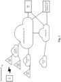
- Fig. 1 shows an exemplary network arrangement 100 according to various exemplary embodiments.
- the exemplary network arrangement 100 includes a UE 110.
- the UE 110 may be any type of electronic component that is configured to communicate via a network, e.g., mobile phones, tablet computers, desktop computers, smartphones, phablets, embedded devices, wearables, Internet of Things (IoT) devices, etc.
- IoT Internet of Things
- an actual network arrangement may include any number of UEs being used by any number of users.
- the example of a single UE 110 is merely provided for illustrative purposes.
- the UE 110 may be configured to communicate with one or more networks.
- the networks with which the UE 110 may wirelessly communicate are a 5G New Radio (NR) radio access network (5G NR-RAN) 120, an LTE radio access network (LTE-RAN) 122 and a wireless local access network (WLAN) 124.
- NR 5G New Radio
- LTE-RAN LTE radio access network
- WLAN wireless local access network
- the UE 110 may also communicate with other types of networks and the UE 110 may also communicate with networks over a wired connection. Therefore, the UE 110 may include a 5G NR chipset to communicate with the 5G NR-RAN 120, an LTE chipset to communicate with the LTE-RAN 122 and an ISM chipset to communicate with the WLAN 124.
- the 5G NR-RAN 120 and the LTE-RAN 122 may be portions of cellular networks that may be deployed by cellular providers (e.g., Verizon, AT&T, Sprint, T-Mobile, etc.). These networks 120, 122 may include, for example, cells or base stations (Node Bs, eNodeBs, HeNBs, eNBS, gNBs, gNodeBs, macrocells, microcells, small cells, femtocells, etc.) that are configured to send and receive traffic from UEs that are equipped with the appropriate cellular chip set.
- the WLAN 124 may include any type of wireless local area network (WiFi, Hot Spot, IEEE 802.11x networks, etc.).
- the UE 110 may connect to the 5G NR-RAN 120 via the gNB 120A or the gNB 120B.
- the gNBs 120A and 120B may be configured with the necessary hardware, software and/or firmware to perform massive multiple in multiple out (MIMO) functionality.
- Massive MIMO may refer to a base station that is configured to generate a plurality of beams for a plurality of UEs.
- the exemplary embodiments will provide manners of handing over the UE 110 from the gNB 120A to the gNB 120B, or vice versa.
- Reference to two gNBs 120A, 120B is merely for illustrative purposes. The exemplary embodiments may apply to any appropriate number of gNBs.
- the UE 110 may communicate with the eNB 122A of the LTE-RAN 122 or an access point of the WLAN 124.
- any association procedure may be performed for the UE 110 to connect to the 5G NR-RAN 120.
- the 5G NR-RAN 120 may be associated with a particular cellular provider where the UE 110 and/or the user thereof has a contract and credential information (e.g., stored on a SIM card).
- the UE 110 may transmit the corresponding credential information to associate with the 5G NR-RAN 120.
- the UE 110 may associate with a specific base station (e.g., the gNB 120A of the 5G NR-RAN 120).
- the network arrangement 100 also includes a cellular core network 130, the Internet 140, an IP Multimedia Subsystem (IMS) 150, and a network services backbone 160.
- the cellular core network 130 may be considered to be the interconnected set of components that manages the operation and traffic of the cellular network.
- the cellular core network 130 also manages the traffic that flows between the cellular network and the Internet 140.
- the IMS 150 may be generally described as an architecture for delivering multimedia services to the UE 110 using the IP protocol.
- the IMS 150 may communicate with the cellular core network 130 and the Internet 140 to provide the multimedia services to the UE 110.
- the network services backbone 160 is in communication either directly or indirectly with the Internet 140 and the cellular core network 130.
- the network services backbone 160 may be generally described as a set of components (e.g., servers, network storage arrangements, etc.) that implement a suite of services that may be used to extend the functionalities of the UE 110 in communication with the various networks.
- Fig. 2 shows an exemplary UE 110 according to various exemplary embodiments.
- the UE 110 will be described with regard to the network arrangement 100 of Fig. 1 .
- the UE 110 may represent any electronic device and may include a processor 205, a memory arrangement 210, a display device 215, an input/output (I/O) device 220, a transceiver 225 and other components 230.
- the other components 230 may include, for example, an audio input device, an audio output device, a battery that provides a limited power supply, a data acquisition device, ports to electrically connect the UE 110 to other electronic devices, one or more antenna panels, etc.
- the processor 205 may be configured to execute a plurality of engines of the UE 110.
- the engines may include a handover engine 235.
- the handover engine 235 may be configured to manage the operation of the UE 110 during a handover procedure from the gNB 120A to the gNB 120B. The specific operations will be described in greater detail below.
- the above referenced engine being an application (e.g., a program) executed by the processor 205 is only exemplary.
- the functionality associated with the engines may also be represented as a separate incorporated component of the UE 110 or may be a modular component coupled to the UE 110, e.g., an integrated circuit with or without firmware.
- the integrated circuit may include input circuitry to receive signals and processing circuitry to process the signals and other information.
- the engines may also be embodied as one application or separate applications.
- the functionality described for the processor 205 is split among two or more processors such as a baseband processor and an applications processor.
- the exemplary embodiments may be implemented in any of these or other configurations of a UE.
- the memory arrangement 210 may be a hardware component configured to store data related to operations performed by the UE 110.
- the display device 215 may be a hardware component configured to show data to a user while the I/O device 220 may be a hardware component that enables the user to enter inputs.
- the display device 215 and the I/O device 220 may be separate components or integrated together such as a touchscreen.
- the transceiver 225 may be a hardware component configured to establish a connection with the 5G NR-RAN 120, the LTE-RAN 122, the WLAN 124, etc. Accordingly, the transceiver 225 may operate on a variety of different frequencies or channels (e.g., set of consecutive frequencies).
- Figs. 3 and 4 will describe signaling associated with two examples of a lower layer based handover command and synchronization procedure.
- the UE 110 is currently connected to the gNB 120A and the handover procedure is being performed to handover the UE to the gNB 120B.
- the gNB 120A will be considered the "source gNB”
- the gNB 120B will be considered the "target gNB.” It should be understood that this is only for illustrative purposes and any gNB may be a source gNB or a target gNB and perform the operations described herein for each of these components.
- Fig. 3 shows a first exemplary signaling diagram 300 for a lower layer based handover command and synchronization procedure according to various exemplary embodiments.
- the signaling diagram 300 may be considered a Random Access Channel (RACH) procedure based handover.
- RACH Random Access Channel
- the source gNB 120A sends a L1/L2 based handover command to the UE 110.
- the L1/L2 based handover command will be described in greater detail below.
- the UE 110 sends an ACK for the L1/L2 handover command to the source gNB 120A. While not shown in the signaling diagram 300, the UE 110 may also send the ACK for the L1/L2 handover command to the target gNB 120B.
- the UE 110 and the target gNB 120B perform the RACH procedure to complete the handover from the source gNB 120A to the target gNB 120B. The details of the L1/L2 based handover command and the RACH procedure will be described in greater detail below.
- Fig. 4 shows a second exemplary signaling diagram 400 for a lower layer based handover command and synchronization procedure according to various exemplary embodiments.
- the signaling diagram 400 may be considered a RACH-less based handover.
- the source gNB 120A sends a L1/L2 based handover command to the UE 110.
- the UE 110 sends an ACK for the L1/L2 handover command to the source gNB 120A.
- the UE 110 and the target gNB 120B exchange handover messages on a configured Physical Uplink Shared Channel (PUSCH) to complete the handover from the source gNB 120A to the target gNB 120B.
- PUSCH Physical Uplink Shared Channel
- Fig. 5 shows a diagram of the UE 110 being handed over from a source gNB 120A to a target gNB 120B according to various exemplary embodiments.
- the source gNB 120A will send a L1/L2 based handover command to the UE 110 to initiate the handover procedure.
- the following describes an exemplary L1/L2 based handover command that will be described with reference to Fig. 5 .
- the gNB to which the UE is currently connected may provide a downlink beam indication based on a Transmission and Configuration Indication (TCI).
- TCI may be used to indicate the quasi-co-location (QCL) source reference signal for a downlink channel (PDSCH, PDCCH).
- PDSCH downlink channel
- PDCCH downlink channel
- Two antenna ports are considered to be quasi-co-located if properties of the channel over which a symbol on one antenna port is conveyed can be inferred from the channel over which a symbol on the other antenna port is conveyed.
- the UE 110 may be configured with a number (S) of TCI state sets. Within each TCI state set, a number (N) of TCI states may be configured. Each TCI state set may correspond to a serving cell.
- TCI state x corresponds to a TCI state set for the source gNB 120A and TCI state y corresponds to a TCI state set for the target gNB 120B.
- This correspondence may be based on a physical cell ID (PCI) that is configured for each of the TCI state sets or each TCI state.
- PCI physical cell ID
- This correspondence allows for implicit association, e.g. gNB can configure different PCIs in different TCI states, and the TCI states that share the same PCI may be considered to belong to the same set.
- the L1/L2 based handover command may be based on a TCI update command that is sent from the source gNB 120A to the UE 110.
- the source gNB 120A is associated with the TCI state x and the target gNB 120B is associated with the TCI state y.
- the source gNB 120A may send a TCI update command that indicates the TCI state y. Since the UE 110 is configured with information indicating that the TCI state y is associated with the target gNB 120B, the UE 110 will understand that the source gNB 120A is signaling that a handover operation should be performed to the handover to the target gNB 120B.
- the L1/L2 based handover command e.g., the TCI update command including the TCI state indication may be included in a Medium Access Control (MAC) Control Element (CE), e.g., a layer 2 message, or in a Downlink Control Information (DCI) message, e.g., a layer 1 message.
- the UE 110 may store various RRC parameters sets associated with different TCI state sets that may then be used for handover. Examples of this stored information will be provided below.
- the exemplary L1/L2 based handover command may be used in operation 310 or 410 for either the RACH based handover or the RACH-less based handover.
- the source gNB 120A may also provide Physical RACH (PRACH) resources to UE 110 to reduce additional latency for beam measurement.
- PRACH Physical RACH
- a PRACH resource may indicate the preamble index and a time/frequency resource for a PRACH transmission.
- the UE 110 may derive the pathloss for PRACH power control based on the synchronization signal blocks (SSB)/ Channel State Indication - Reference Signal (CSI-RS) configured in the TCI state.
- SSB synchronization signal blocks
- CSI-RS Channel State Indication - Reference Signal
- the source gNB 120A may configure a PRACH resource from the target cell 120B by RRC signaling.
- the RRC signaling described in this example is RRC signaling that occurs prior to the start of the handover procedure, e.g., during the normal course of RRC signaling that occurs while the UE 110 is connected to the gNB 120A.
- the UE 110 may store various RRC parameters sets associated with different TCI state sets.
- the source GNB 120A may include an indication of a PRACH resource for a TCI state.
- the UE 110 receives the L1/L2 based handover command that includes a TCI state, the UE 110 can retrieve the information associated with the TCI state that includes the PRACH resource.
- the UE 110 may then start the RACH procedure (e.g., operation 330 of Fig. 3 ) based on the configured PRACH resource.
- the initial attempt at the RACH procedure 330 may be a contention-free based RACH procedure.
- the UE 110 may monitor for a response after transmitting the PRACH, and, if after a given time window, the UE 110 does not receive any response, the UE may then fallback to use a contention-based RACH procedure. Completion of the RACH procedure 330 will complete the handover from the source gNB 120A to the target gNB 120B.
- Fig. 6 shows a block diagram 600 of a relationship between a TCI state 610, a SSBs 620, 625 and PRACH resources 630 for a RACH based handover according to various exemplary embodiments.
- the source gNB 120A may configure a SSB or CSI-RS that is QCLed with a SSB.
- the TCI state 1 610 is associated with the target gNB 120B.
- the SSB 620 is associated with the TCI 1 state 610 and the PRACH resources 631-634.
- the association between the PRACH resources 631-634 and the SSB 620 from the target cell 120B may again be configured by RRC signaling in a similar manner as was described above with reference to the TCI state information.
- the UE 110 may randomly select one of associated PRACH resources (e.g., PRACH resource 632) based on the SSB 620 associated with the TCI 1 state 610 of the target gNB 120B and perform a contention-based RACH procedure in 330.
- the radio network temporary ID (RNTI) of the UE 110 in the target cell may be configured for each TCI state.
- the UE 110 may transmit a Msg3 to the target gNB 120B that includes the RNTI.
- the target gNB 120B may not provide the UE 110 with the new RNTI. In this case, the UE 110 may transmit a Msg3 with the initial UE-ID for collision handling.
- Fig. 7 shows a scheduling diagram 700 for a RACH-less handover according to various exemplary embodiments.
- the operations described with reference to scheduling diagram 700 are related to the PUSCH signaling 430 described above with reference to Fig. 4 .
- the UE 110 sends a PUSCH message to the target gNB 120B.
- the PUSCH resource that is used by the UE 110 to communicate with the target gNB 120B may be configured in various manners.
- a PUSCH resource can be configured for each TCI state. Again, this information may be stored by the UE 110 based on RRC signaling from the source gNB 120A.
- the PUSCH configuration may include, a Modulation and Coding Scheme
- the UE 110 may use the same beam to transmit the PUSCH as that to receive the SSB/CSI-RS configured in the TCI state. In addition, the UE 110 may derive the pathloss for PUSCH power control based on the SSB/CSI-RS configured in the TCI state.
- the PUSCH resource may be triggered by a PDCCH or MAC CE from the source gNB 120A.
- an indicator in the DCI may indicate whether the PDCCH is to trigger a PUSCH to the source gNB 120A or the target gNB 120B.
- the PUSCH resource may be indicated by the L1/L2 handover command from the source gNB 120A.
- the initial scrambler of the PUSCH at 710 may be determined based on any of the configured RNTI from the source gNB 120A, an index of random access preambles or a virtual cell ID for the target gNB 120B.
- the UE 110 may also derive a timing advance (TA) for the PUSCH transmission 710.
- TA timing advance
- the TA may be assumed to be 0.
- the TA may be configured by the source gNB 120A.
- the TA may be configured per TCI state set or per TCI state.
- the TA may be based on measurements of a CSI-RS configured in the TCI state.
- the CSI-RS may be configured based on one or more of the following rules.
- the CSI-RS may be 1-port.
- the target gNB 120B responds to the PUSCH message from the UE 110.
- the target gNB 120B response may be based on a PDCCH.
- the target gNB 120B may schedule an uplink (UL) transmission with a scheduling offset K.
- the scheduling offset K may be determined as K2+delta, where K2 is the minimal scheduling offset and delta is the additional scheduling offset, which is predefined based on the subcarrier spacing of the PUSCH.
- the UE 110 may then perform the UL transmission to the target gNB 120B. Once this is completed, the handover procedure is complete and the UE 110 is connected to the target gNB 120B.
- An exemplary hardware platform for implementing the exemplary embodiments may include, for example, an Intel x86 based platform with compatible operating system, a Windows OS, a Mac platform and MAC OS, a mobile device having an operating system such as iOS, Android, etc.
- the exemplary embodiments of the above described method may be embodied as a program containing lines of code stored on a non-transitory computer readable storage medium that, when compiled, may be executed on a processor or microprocessor.
- personally identifiable information should follow privacy policies and practices that are generally recognized as meeting or exceeding industry or governmental requirements for maintaining the privacy of users.
- personally identifiable information data should be managed and handled so as to minimize risks of unintentional or unauthorized access or use, and the nature of authorized use should be clearly indicated to users.
Landscapes
- Engineering & Computer Science (AREA)
- Computer Networks & Wireless Communication (AREA)
- Signal Processing (AREA)
- Mobile Radio Communication Systems (AREA)
Abstract
Description
- A user equipment (UE) may establish a connection to at least one of multiple different networks or types of networks. The UE may establish this connection by connecting to a base station (e.g., large cell, small cell, access point, etc.) of a network. As a UE moves, the UE may have to switch from a first base station to a second base station to maintain the connection to the network. This switching from a first base station to a second base station is referred to as a handover, e.g., the first base station is handing the UE over to the second base station.
- In Rel. 15 and 16 of the 3GPP standards handovers are controlled based on Radio Resource Control (RRC) signaling between the base stations and the UE. Those skilled in the art will understand that the RRC protocol is an Internet Protocol (IP) level layer or a Layer 3 protocol.
- Some exemplary embodiments are related to a user equipment (UE) having a transceiver and a baseband processor. The transceiver is configured to connect to a first next generation Node B (gNB) of a 5G new radio (NR) network. The baseband processor is configured to receive a handover command from the first gNB via one of a Layer 1 signaling or Layer 2 signaling that instructs the UE to perform a handover procedure to handover to a second gNB, and conduct the handover procedure with the second gNB for the UE to connect to the second gNB.
- Other exemplary embodiments are related to a computer readable storage medium having a set of instructions, which when executed by a processor cause the processor to perform operations. The operations include receiving a handover command from a first next generation Node B (gNB) of a 5G new radio (NR) network via one of a Layer 1 signaling or Layer 2 signaling, the handover instructing a user equipment (UE) to perform a handover procedure to handover to a second gNB and conducting the handover procedure with the second gNB.
- Still other exemplary embodiments are related to a first next generation Node B (gNB) of a 5G new radio (NR) network that has a transceiver and a baseband processor. The transceiver is configured to connect to a user equipment (UE). The baseband processor is configured to instruct the UE to perform a handover procedure from the first gNB to a second gNB based on a handover command that is transmitted from the first gNB via one of a Layer 1 signaling or Layer 2 signaling, wherein the handover command comprises an identification of a Transmission and Configuration Indication (TCI) state that is associated with the second gNB.
-
-
Fig. 1 shows an exemplary network arrangement according to various exemplary embodiments. -
Fig. 2 shows an exemplary UE according to various exemplary embodiments. -
Fig. 3 shows a first exemplary signaling diagram for a Random Access Channel (RACH) based lower layer based handover command and synchronization procedure according to various exemplary embodiments. -
Fig. 4 shows a second exemplary signaling diagram for a RACH-less lower layer based handover command and synchronization procedure according to various exemplary embodiments. -
Fig. 5 shows a diagram of the UE being handed over from a source next generation NodeB (gNB) to a target gNB according to various exemplary embodiments. -
Fig. 6 shows a block diagram of a relationship between a Transmission and Configuration Indication (TCI) state, a synchronization signal block (SSB) and Physical RACH (PRACH) resources for a RACH based handover according to various exemplary embodiments. -
Fig. 7 shows a scheduling diagram for a RACH-less handover according to various exemplary embodiments. - The exemplary embodiments may be further understood with reference to the following description and the related appended drawings, wherein like elements are provided with the same reference numerals. The exemplary embodiments relate to a handover for a UE from a first base station to a second base station using lower layer (e.g., layer 1 and/or 2) signaling.
- The exemplary embodiments are described with regard to a UE. However, reference to a UE is merely provided for illustrative purposes. The exemplary embodiments may be utilized with any electronic component that may establish a connection to a network and is configured with the hardware, software, and/or firmware to exchange information and data with the network. Therefore, the UE as described herein is used to represent any electronic component.
- The exemplary embodiments are also described with regard to 5G new radio (NR) radio access technology (RAT). However, it should be understood that 5G NR is being used for illustrative purposes and the exemplary embodiments may be applied to any network that exhibits the characteristics and functionalities described below for the 5G NR network.
- The exemplary embodiments relate to using lower layer (e.g., layer 1 and/or 2 "L1/L2") signaling for the handover procedure. Using the lower layers for handover may reduce the latency and signaling overhead associated with the handover procedure. In general, the exemplary embodiments start the handover procedure using L1/L2 signaling from a base station. The UE receives the corresponding signaling and then synchronizes to the target cell. The exemplary embodiments address the issues of the signaling details for the L1/L2 signaling and the UE behavior to synchronize to the target cell. The exemplary embodiments will be described in detail below.
-
Fig. 1 shows anexemplary network arrangement 100 according to various exemplary embodiments. Theexemplary network arrangement 100 includes a UE 110. Those skilled in the art will understand that the UE 110 may be any type of electronic component that is configured to communicate via a network, e.g., mobile phones, tablet computers, desktop computers, smartphones, phablets, embedded devices, wearables, Internet of Things (IoT) devices, etc. It should also be understood that an actual network arrangement may include any number of UEs being used by any number of users. Thus, the example of a single UE 110 is merely provided for illustrative purposes. - The UE 110 may be configured to communicate with one or more networks. In the example of the
network configuration 100, the networks with which the UE 110 may wirelessly communicate are a 5G New Radio (NR) radio access network (5G NR-RAN) 120, an LTE radio access network (LTE-RAN) 122 and a wireless local access network (WLAN) 124. However, it should be understood that the UE 110 may also communicate with other types of networks and the UE 110 may also communicate with networks over a wired connection. Therefore, the UE 110 may include a 5G NR chipset to communicate with the 5G NR-RAN 120, an LTE chipset to communicate with the LTE-RAN 122 and an ISM chipset to communicate with theWLAN 124. - The 5G NR-RAN 120 and the LTE-RAN 122 may be portions of cellular networks that may be deployed by cellular providers (e.g., Verizon, AT&T, Sprint, T-Mobile, etc.). These
networks - The UE 110 may connect to the 5G NR-RAN 120 via the gNB 120A or the gNB 120B. The gNBs 120A and 120B may be configured with the necessary hardware, software and/or firmware to perform massive multiple in multiple out (MIMO) functionality. Massive MIMO may refer to a base station that is configured to generate a plurality of beams for a plurality of UEs. As will be described in greater detail below, the exemplary embodiments will provide manners of handing over the UE 110 from the gNB 120A to the gNB 120B, or vice versa. Reference to two
gNBs RAN 122 or an access point of theWLAN 124. - Those skilled in the art will understand that any association procedure may be performed for the UE 110 to connect to the 5G NR-
RAN 120. For example, as discussed above, the 5G NR-RAN 120 may be associated with a particular cellular provider where the UE 110 and/or the user thereof has a contract and credential information (e.g., stored on a SIM card). Upon detecting the presence of the 5G NR-RAN 120, the UE 110 may transmit the corresponding credential information to associate with the 5G NR-RAN 120. More specifically, the UE 110 may associate with a specific base station (e.g., the gNB 120A of the 5G NR-RAN 120). - In addition to the
networks network arrangement 100 also includes acellular core network 130, the Internet 140, an IP Multimedia Subsystem (IMS) 150, and anetwork services backbone 160. Thecellular core network 130 may be considered to be the interconnected set of components that manages the operation and traffic of the cellular network. Thecellular core network 130 also manages the traffic that flows between the cellular network and the Internet 140. TheIMS 150 may be generally described as an architecture for delivering multimedia services to theUE 110 using the IP protocol. TheIMS 150 may communicate with thecellular core network 130 and theInternet 140 to provide the multimedia services to theUE 110. Thenetwork services backbone 160 is in communication either directly or indirectly with theInternet 140 and thecellular core network 130. Thenetwork services backbone 160 may be generally described as a set of components (e.g., servers, network storage arrangements, etc.) that implement a suite of services that may be used to extend the functionalities of theUE 110 in communication with the various networks. -
Fig. 2 shows anexemplary UE 110 according to various exemplary embodiments. TheUE 110 will be described with regard to thenetwork arrangement 100 ofFig. 1 . TheUE 110 may represent any electronic device and may include aprocessor 205, a memory arrangement 210, a display device 215, an input/output (I/O) device 220, a transceiver 225 and other components 230. The other components 230 may include, for example, an audio input device, an audio output device, a battery that provides a limited power supply, a data acquisition device, ports to electrically connect theUE 110 to other electronic devices, one or more antenna panels, etc. - The
processor 205 may be configured to execute a plurality of engines of theUE 110. For example, the engines may include ahandover engine 235. Thehandover engine 235 may be configured to manage the operation of theUE 110 during a handover procedure from thegNB 120A to thegNB 120B. The specific operations will be described in greater detail below. - The above referenced engine being an application (e.g., a program) executed by the
processor 205 is only exemplary. The functionality associated with the engines may also be represented as a separate incorporated component of theUE 110 or may be a modular component coupled to theUE 110, e.g., an integrated circuit with or without firmware. For example, the integrated circuit may include input circuitry to receive signals and processing circuitry to process the signals and other information. The engines may also be embodied as one application or separate applications. In addition, in some UEs, the functionality described for theprocessor 205 is split among two or more processors such as a baseband processor and an applications processor. The exemplary embodiments may be implemented in any of these or other configurations of a UE. - The memory arrangement 210 may be a hardware component configured to store data related to operations performed by the
UE 110. The display device 215 may be a hardware component configured to show data to a user while the I/O device 220 may be a hardware component that enables the user to enter inputs. The display device 215 and the I/O device 220 may be separate components or integrated together such as a touchscreen. The transceiver 225 may be a hardware component configured to establish a connection with the 5G NR-RAN 120, the LTE-RAN 122, theWLAN 124, etc. Accordingly, the transceiver 225 may operate on a variety of different frequencies or channels (e.g., set of consecutive frequencies). -
Figs. 3 and 4 will describe signaling associated with two examples of a lower layer based handover command and synchronization procedure. Prior to describing the signaling ofFigs. 3 and 4 , it is noted that throughout this description it will be considered that theUE 110 is currently connected to thegNB 120A and the handover procedure is being performed to handover the UE to thegNB 120B. Thus, thegNB 120A will be considered the "source gNB" and thegNB 120B will be considered the "target gNB." It should be understood that this is only for illustrative purposes and any gNB may be a source gNB or a target gNB and perform the operations described herein for each of these components. -
Fig. 3 shows a first exemplary signaling diagram 300 for a lower layer based handover command and synchronization procedure according to various exemplary embodiments. The signaling diagram 300 may be considered a Random Access Channel (RACH) procedure based handover. - In 310, the
source gNB 120A sends a L1/L2 based handover command to theUE 110. The L1/L2 based handover command will be described in greater detail below. In 320, theUE 110 sends an ACK for the L1/L2 handover command to thesource gNB 120A. While not shown in the signaling diagram 300, theUE 110 may also send the ACK for the L1/L2 handover command to thetarget gNB 120B. In 330, theUE 110 and thetarget gNB 120B perform the RACH procedure to complete the handover from thesource gNB 120A to thetarget gNB 120B. The details of the L1/L2 based handover command and the RACH procedure will be described in greater detail below. -
Fig. 4 shows a second exemplary signaling diagram 400 for a lower layer based handover command and synchronization procedure according to various exemplary embodiments. The signaling diagram 400 may be considered a RACH-less based handover. - In 410, the
source gNB 120A sends a L1/L2 based handover command to theUE 110. In 420, theUE 110 sends an ACK for the L1/L2 handover command to thesource gNB 120A. In 430, theUE 110 and thetarget gNB 120B exchange handover messages on a configured Physical Uplink Shared Channel (PUSCH) to complete the handover from thesource gNB 120A to thetarget gNB 120B. The details of the L1/L2 based handover command and the PUSCH messaging will be described in greater detail below. -
Fig. 5 shows a diagram of theUE 110 being handed over from asource gNB 120A to atarget gNB 120B according to various exemplary embodiments. As described above, in 310 and 410, thesource gNB 120A will send a L1/L2 based handover command to theUE 110 to initiate the handover procedure. The following describes an exemplary L1/L2 based handover command that will be described with reference toFig. 5 . - The gNB to which the UE is currently connected (e.g.,
gNB 120A) may provide a downlink beam indication based on a Transmission and Configuration Indication (TCI). The TCI may be used to indicate the quasi-co-location (QCL) source reference signal for a downlink channel (PDSCH, PDCCH). Two antenna ports are considered to be quasi-co-located if properties of the channel over which a symbol on one antenna port is conveyed can be inferred from the channel over which a symbol on the other antenna port is conveyed. TheUE 110 may be configured with a number (S) of TCI state sets. Within each TCI state set, a number (N) of TCI states may be configured. Each TCI state set may correspond to a serving cell. For example, inFig. 5 , it may be considered that TCI state x corresponds to a TCI state set for thesource gNB 120A and TCI state y corresponds to a TCI state set for thetarget gNB 120B. This correspondence may be based on a physical cell ID (PCI) that is configured for each of the TCI state sets or each TCI state. This correspondence allows for implicit association, e.g. gNB can configure different PCIs in different TCI states, and the TCI states that share the same PCI may be considered to belong to the same set. - The L1/L2 based handover command may be based on a TCI update command that is sent from the
source gNB 120A to theUE 110. For example, as described in the above example, thesource gNB 120A is associated with the TCI state x and thetarget gNB 120B is associated with the TCI state y. Thus, in the L1/L2 based handover command, thesource gNB 120A may send a TCI update command that indicates the TCI state y. Since theUE 110 is configured with information indicating that the TCI state y is associated with thetarget gNB 120B, theUE 110 will understand that thesource gNB 120A is signaling that a handover operation should be performed to the handover to thetarget gNB 120B. - The L1/L2 based handover command, e.g., the TCI update command including the TCI state indication may be included in a Medium Access Control (MAC) Control Element (CE), e.g., a layer 2 message, or in a Downlink Control Information (DCI) message, e.g., a layer 1 message. The
UE 110 may store various RRC parameters sets associated with different TCI state sets that may then be used for handover. Examples of this stored information will be provided below. The exemplary L1/L2 based handover command may be used inoperation - The following provides additional information that may be used for the RACH based handover procedure as was described above with respect to
Fig. 3 . For example, since a RACH procedure is being used and the candidate beam for thetarget cell 120B has been identified, e.g., the TCI state y, thesource gNB 120A may also provide Physical RACH (PRACH) resources toUE 110 to reduce additional latency for beam measurement. A PRACH resource may indicate the preamble index and a time/frequency resource for a PRACH transmission. TheUE 110 may derive the pathloss for PRACH power control based on the synchronization signal blocks (SSB)/ Channel State Indication - Reference Signal (CSI-RS) configured in the TCI state. - In a first exemplary embodiment, for each TCI state, the
source gNB 120A may configure a PRACH resource from thetarget cell 120B by RRC signaling. The RRC signaling described in this example is RRC signaling that occurs prior to the start of the handover procedure, e.g., during the normal course of RRC signaling that occurs while theUE 110 is connected to thegNB 120A. As described above, theUE 110 may store various RRC parameters sets associated with different TCI state sets. For example, as part of the TCI state information that is signaled to theUE 110, thesource GNB 120A may include an indication of a PRACH resource for a TCI state. When theUE 110 receives the L1/L2 based handover command that includes a TCI state, theUE 110 can retrieve the information associated with the TCI state that includes the PRACH resource. - The
UE 110 may then start the RACH procedure (e.g.,operation 330 ofFig. 3 ) based on the configured PRACH resource. The initial attempt at theRACH procedure 330 may be a contention-free based RACH procedure. TheUE 110 may monitor for a response after transmitting the PRACH, and, if after a given time window, theUE 110 does not receive any response, the UE may then fallback to use a contention-based RACH procedure. Completion of theRACH procedure 330 will complete the handover from thesource gNB 120A to thetarget gNB 120B. -
Fig. 6 shows a block diagram 600 of a relationship between aTCI state 610, aSSBs source gNB 120A may configure a SSB or CSI-RS that is QCLed with a SSB. In this example, it may be considered that the TCI state 1 610 is associated with thetarget gNB 120B. TheSSB 620 is associated with the TCI 1state 610 and the PRACH resources 631-634. The association between the PRACH resources 631-634 and theSSB 620 from thetarget cell 120B may again be configured by RRC signaling in a similar manner as was described above with reference to the TCI state information. - In this exemplary embodiment, the
UE 110 may randomly select one of associated PRACH resources (e.g., PRACH resource 632) based on theSSB 620 associated with the TCI 1state 610 of thetarget gNB 120B and perform a contention-based RACH procedure in 330. For example, in some embodiments, the radio network temporary ID (RNTI) of theUE 110 in the target cell may be configured for each TCI state. TheUE 110 may transmit a Msg3 to thetarget gNB 120B that includes the RNTI. In other embodiments, thetarget gNB 120B may not provide theUE 110 with the new RNTI. In this case, theUE 110 may transmit a Msg3 with the initial UE-ID for collision handling. - The following provides additional information that may be used for the RACH-less based handover procedure as was described above with respect to
Fig. 4 .Fig. 7 shows a scheduling diagram 700 for a RACH-less handover according to various exemplary embodiments. The operations described with reference to scheduling diagram 700 are related to the PUSCH signaling 430 described above with reference toFig. 4 . - At 710, the
UE 110 sends a PUSCH message to thetarget gNB 120B. The PUSCH resource that is used by theUE 110 to communicate with thetarget gNB 120B may be configured in various manners. In some exemplary embodiments, a PUSCH resource can be configured for each TCI state. Again, this information may be stored by theUE 110 based on RRC signaling from thesource gNB 120A. The PUSCH configuration may include, a Modulation and Coding Scheme - (MCS), an allocated bandwidth, time resources, DMRS port index, power control parameters, etc. The
UE 110 may use the same beam to transmit the PUSCH as that to receive the SSB/CSI-RS configured in the TCI state. In addition, theUE 110 may derive the pathloss for PUSCH power control based on the SSB/CSI-RS configured in the TCI state. - In other exemplary embodiments, the PUSCH resource may be triggered by a PDCCH or MAC CE from the
source gNB 120A. In one example, an indicator in the DCI may indicate whether the PDCCH is to trigger a PUSCH to thesource gNB 120A or thetarget gNB 120B. In another example, the PUSCH resource may be indicated by the L1/L2 handover command from thesource gNB 120A. - The initial scrambler of the PUSCH at 710 may be determined based on any of the configured RNTI from the
source gNB 120A, an index of random access preambles or a virtual cell ID for thetarget gNB 120B. - The
UE 110 may also derive a timing advance (TA) for thePUSCH transmission 710. There may be various options for deriving the TA. In a first example, the TA may be assumed to be 0. In a second example, the TA may be configured by thesource gNB 120A. For example, the TA may be configured per TCI state set or per TCI state. - In a third example, the TA may be based on measurements of a CSI-RS configured in the TCI state. To improve the TA measurement accuracy, the CSI-RS may be configured based on one or more of the following rules. The CSI-RS may be 1-port. The frequency density for the CSI-RS may be at least x resource elements/resource block (REs/RB), e.g. x=3. The minimal bandwidth for the CSI-RS may be min{N_RB_max, N1}, where N_RB_max indicates the maximum number of RBs for the bandwidth part and N1 is a predefined value, e.g. N1=52, or based on the capability of the UE.
- At 720, the
target gNB 120B responds to the PUSCH message from theUE 110. Thetarget gNB 120B response may be based on a PDCCH. As part of the response in 720, thetarget gNB 120B may schedule an uplink (UL) transmission with a scheduling offset K. The scheduling offset K may be determined as K2+delta, where K2 is the minimal scheduling offset and delta is the additional scheduling offset, which is predefined based on the subcarrier spacing of the PUSCH. - At 730, the
UE 110 may then perform the UL transmission to thetarget gNB 120B. Once this is completed, the handover procedure is complete and theUE 110 is connected to thetarget gNB 120B. - Those skilled in the art will understand that the above-described exemplary embodiments may be implemented in any suitable software or hardware configuration or combination thereof. An exemplary hardware platform for implementing the exemplary embodiments may include, for example, an Intel x86 based platform with compatible operating system, a Windows OS, a Mac platform and MAC OS, a mobile device having an operating system such as iOS, Android, etc. In a further example, the exemplary embodiments of the above described method may be embodied as a program containing lines of code stored on a non-transitory computer readable storage medium that, when compiled, may be executed on a processor or microprocessor.
- Although this application described various embodiments each having different features in various combinations, those skilled in the art will understand that any of the features of one embodiment may be combined with the features of the other embodiments in any manner not specifically disclaimed or which is not functionally or logically inconsistent with the operation of the device or the stated functions of the disclosed embodiments.
- It is well understood that the use of personally identifiable information should follow privacy policies and practices that are generally recognized as meeting or exceeding industry or governmental requirements for maintaining the privacy of users. In particular, personally identifiable information data should be managed and handled so as to minimize risks of unintentional or unauthorized access or use, and the nature of authorized use should be clearly indicated to users.
- It will be apparent to those skilled in the art that various modifications may be made in the present disclosure, without departing from the spirit or the scope of the disclosure. Thus, it is intended that the present disclosure cover modifications and variations of this disclosure provided they come within the scope of the appended claims and their equivalent.
-
- 1. A user equipment (UE), comprising:
- a transceiver configured to connect to a first next generation Node B (gNB) of a 5G new radio (NR) network; and
- a baseband processor configured to:
- receive a handover command from the first gNB via one of a Layer 1 signaling or Layer 2 signaling that instructs the UE to perform a handover procedure to handover to a second gNB, and
- conduct the handover procedure with the second gNB for the UE to connect to the second gNB.
- 2. The UE of statement 1, wherein the Layer 1 signaling or Layer 2 signaling comprises one of a Medium Access Control (MAC) Control Element (CE) or a Downlink Control Information (DCI) message.
- 3. The UE of statement 1, wherein the handover command comprises an identification of a Transmission and Configuration Indication (TCI) state that is associated with the second gNB.
- 4. The UE of statement 3, further comprising:
a memory configured to store a relationship between the second gNB and the identified TCI state and further store relationships between the identified TCI state and parameters to perform the handover procedure. - 5. The UE of statement 1, wherein the handover procedure includes performing a Random Access Channel (RACH) procedure between the UE and the second gNB.
- 6. The UE of statement 5, wherein the UE is informed, by the first gNB, of a Physical RACH (PRACH) resource on which to perform the RACH procedure prior to receiving the handover command.
- 7. The UE of statement 6, wherein the attempts a contention-free RACH procedure on the identified PRACH resource.
- 8. The UE of statement 5, wherein the handover command comprises an identification of a Transmission and Configuration Indication (TCI) state that is associated with the second gNB and wherein the UE includes synchronization signal block (SSB) and PRACH resources corresponding to the identified TCI state, wherein the baseband processor performs a contention based RACH procedure on one of the PRACH resources corresponding to the identified TCI state.
- 9. The UE of statement 1, wherein the handover procedure includes performing Physical Uplink Shared Channel (PUSCH) messaging between the UE and the second gNB.
- 10. The UE of statement 9, wherein a PUSCH resource to perform the PUSCH messaging is one of (i) related to a Transmission and Configuration Indication (TCI) state indicated in the handover command, or (ii) signaled to the UE from the first gNB.
- 11. The UE of statement 9, wherein the baseband processor is configured to determine a timing advance (TA) for a PUSCH resource.
- 12. The UE of statement 11, wherein the TA is determined based on at least one of (i) a predetermined value, (ii) information received from the first gNB, or (iii) measurements of a Channel State Indication - Reference Signal (CSI-RS).
- 13. A computer readable storage medium comprising a set of instructions, which when executed by a processor cause the processor to perform operations comprising:
- receiving a handover command from a first next generation Node B (gNB) of a 5G new radio (NR) network via one of a Layer 1 signaling or Layer 2 signaling, the handover instructing a user equipment (UE) to perform a handover procedure to handover to a second gNB; and
- conducting the handover procedure with the second gNB.
- 14. The computer readable storage medium of statement 13, wherein the handover procedure includes performing a Random Access Channel (RACH) procedure between the UE and the second gNB.
- 15. The computer readable storage medium of statement 14, wherein the operations further comprise:
- receiving, from the first gNB and prior to receiving the handover command, an indication of a Physical RACH (PRACH) resource on which to perform the RACH procedure; and
- attempting a contention-free RACH procedure with the second gNB on the identified PRACH resource.
- 16. The computer readable storage medium of statement 13, wherein the handover procedure includes performing Physical Uplink Shared Channel (PUSCH) messaging between the UE and the second gNB, wherein a PUSCH resource to perform the PUSCH messaging is one of (i) related to a Transmission and Configuration Indication (TCI) state indicated in the handover command, or (ii) signaled to the UE from the first gNB.
- 17. A first next generation Node B (gNB) of a 5G new radio (NR) network, comprising:
- a transceiver configured to connect to a user equipment (UE) ;
- a baseband processor configured to instruct the UE to perform a handover procedure from the first gNB to a second gNB based on a handover command that is transmitted from the first gNB via one of a Layer 1 signaling or Layer 2 signaling, wherein the handover command comprises an identification of a Transmission and Configuration Indication (TCI) state that is associated with the second gNB.
- 18. The gNB of statement 17, wherein the Layer 1 signaling or Layer 2 signaling comprises one of a Medium Access Control (MAC) Control Element (CE) or a Downlink Control Information (DCI) message.
- 19. The gNB of statement 17, wherein the baseband processor informs the UE of a Physical Random Access Channel (PRACH) resource on which to perform a RACH procedure for the handover procedure.
- 20. The gNB of statement 17, wherein the baseband processor informs the UE of a Physical Uplink Shared Channel (PUSCH) resource to perform PUSCH messaging for the handover procedure, wherein the baseband processor informs the UE via one of a Physical Downlink Control Channel (PDCCH) message or a Downlink Control Information (DCI) message.
Claims (13)
- An apparatus comprising processing circuitry configured to:generate, for transmission to a user equipment, UE, (110), a handover command via one of a Layer 1 signaling or Layer 2 signaling that instructs the UE (110) to perform a handover procedure to handover to a next generation Node B, gNB, (120B), of a 5G new radio, wherein the handover command comprises an identification of a Transmission and Configuration Indication, TCI, state that is associated with the gNB (120B); andprocess, based on signaling from the UE (110), an acknowledgement, ACK, corresponding to the handover command.
- The apparatus of claim 1, wherein the Layer 1 signaling or Layer 2 signaling comprises one of a Medium Access Control, MAC, Control Element, CE, or a Downlink Control Information, DCI message.
- The apparatus of either of claims 1 or 2, wherein the processing circuitry is further configured to:
generate, for transmission to the UE (110), a message comprising an identification of a Physical Random Access Channel, PRACH, resource on which to perform a Random Access Channel, RACH, procedure between the UE (110) and the gNB (120B), wherein the message is transmitted prior to the handover command. - The apparatus of claim 3, wherein the TCI state that is associated with the gNB (120B) corresponds to the PRACH resources.
- A next generation node B, gNB, comprising the apparatus of any of claims 1-4.
- A computer readable storage medium comprising a set of instructions, which when executed by a processor cause the processor to perform operations comprising:generating, for transmission to a user equipment, UE, (110), a handover command via one of a Layer 1 signaling or Layer 2 signaling that instructs the UE (110) to perform a handover procedure to handover to a next generation Node B, gNB, (120B), of a 5G new radio, wherein the handover command comprises an identification of a Transmission and Configuration Indication, TCI, state that is associated with the gNB (120B); andprocessing, based on signaling from the UE (110), an acknowledgement, ACK, corresponding to the handover command.
- The computer readable storage medium of claim 6, wherein the Layer 1 signaling or Layer 2 signaling comprises one of a Medium Access Control, MAC, Control Element, CE, or a Downlink Control Information, DCI message.
- The computer readable storage medium of either of claims 6 or 7, wherein the operations further comprise:
generating, for transmission to the UE (110), a message comprising an identification of a Physical Random Access Channel, PRACH, resource on which to perform a Random Access Channel, RACH, procedure between the UE (110) and the gNB (120B), wherein the message is transmitted prior to the handover command. - The computer readable storage medium of claim 8, wherein the TCI state that is associated with the gNB (120B) corresponds to the PRACH resources.
- A method, comprising:generating, for transmission to a user equipment, UE, (110), a handover command via one of a Layer 1 signaling or Layer 2 signaling that instructs the UE (110) to perform a handover procedure to handover to a next generation Node B, gNB, (120B), of a 5G new radio, wherein the handover command comprises an identification of a Transmission and Configuration Indication, TCI, state that is associated with the gNB (120B); andprocessing, based on signaling from the UE (110), an acknowledgement, ACK, corresponding to the handover command.
- The method of claim 10, wherein the Layer 1 signaling or Layer 2 signaling comprises one of a Medium Access Control, MAC, Control Element, CE, or a Downlink Control Information, DCI message.
- The method of either of claims 10 or 11, wherein the operations further comprise:
generating, for transmission to the UE (110), a message comprising an identification of a Physical Random Access Channel, PRACH, resource on which to perform a Random Access Channel, RACH, procedure between the UE (110) and the gNB (120B), wherein the message is transmitted prior to the handover command. - The method of claim 12, wherein the TCI state that is associated with the gNB (120B) corresponds to the PRACH resources.
Priority Applications (1)
| Application Number | Priority Date | Filing Date | Title |
|---|---|---|---|
| EP24199472.2A EP4456605A3 (en) | 2020-05-14 | 2020-05-14 | Low-layer based mobility management |
Applications Claiming Priority (3)
| Application Number | Priority Date | Filing Date | Title |
|---|---|---|---|
| EP20935492.7A EP4133696B1 (en) | 2020-05-14 | 2020-05-14 | Low-layer based mobility management |
| EP24199472.2A EP4456605A3 (en) | 2020-05-14 | 2020-05-14 | Low-layer based mobility management |
| PCT/CN2020/090264 WO2021226934A1 (en) | 2020-05-14 | 2020-05-14 | Synchronization for low-layer based mobility management |
Related Parent Applications (2)
| Application Number | Title | Priority Date | Filing Date |
|---|---|---|---|
| EP20935492.7A Division-Into EP4133696B1 (en) | 2020-05-14 | 2020-05-14 | Low-layer based mobility management |
| EP20935492.7A Division EP4133696B1 (en) | 2020-05-14 | 2020-05-14 | Low-layer based mobility management |
Publications (2)
| Publication Number | Publication Date |
|---|---|
| EP4456605A2 true EP4456605A2 (en) | 2024-10-30 |
| EP4456605A3 EP4456605A3 (en) | 2025-01-22 |
Family
ID=78526176
Family Applications (2)
| Application Number | Title | Priority Date | Filing Date |
|---|---|---|---|
| EP24199472.2A Pending EP4456605A3 (en) | 2020-05-14 | 2020-05-14 | Low-layer based mobility management |
| EP20935492.7A Active EP4133696B1 (en) | 2020-05-14 | 2020-05-14 | Low-layer based mobility management |
Family Applications After (1)
| Application Number | Title | Priority Date | Filing Date |
|---|---|---|---|
| EP20935492.7A Active EP4133696B1 (en) | 2020-05-14 | 2020-05-14 | Low-layer based mobility management |
Country Status (5)
| Country | Link |
|---|---|
| US (1) | US20220312286A1 (en) |
| EP (2) | EP4456605A3 (en) |
| KR (1) | KR20230007376A (en) |
| CN (2) | CN115552849B (en) |
| WO (1) | WO2021226934A1 (en) |
Families Citing this family (11)
| Publication number | Priority date | Publication date | Assignee | Title |
|---|---|---|---|---|
| CN120499756A (en) * | 2020-05-15 | 2025-08-15 | 苹果公司 | Generating filtering results in user equipment triggered lower layer based handover |
| EP4478786A4 (en) * | 2022-02-08 | 2026-01-14 | Kyocera Corp | COMMUNICATION METHOD, USER DEVICE AND BASE STATION |
| JP2025510784A (en) | 2022-03-24 | 2025-04-15 | 日本電気株式会社 | UE, RAN node and method |
| KR20250005140A (en) * | 2022-04-22 | 2025-01-09 | 지티이 코포레이션 | Method and system for performing high-speed mobility based on lower layer signaling |
| WO2024013665A2 (en) * | 2022-07-12 | 2024-01-18 | Guangdong Oppo Mobile Telecommunications Corp., Ltd. | Methods and apparatus of tci state application during l1/l2 based inter-cell mobility |
| KR20240063643A (en) * | 2022-11-03 | 2024-05-10 | 삼성전자주식회사 | Method and apparatus for configurating tci state for switching cell |
| GB2624041A (en) * | 2022-11-07 | 2024-05-08 | Nokia Technologies Oy | Mobility in wireless communication systems |
| EP4666686A1 (en) * | 2023-02-14 | 2025-12-24 | Apple Inc. | Systems and methods for cell switching command construction and use |
| KR102876768B1 (en) | 2023-03-14 | 2025-10-28 | 주식회사 블랙핀 | Method and Apparatus for preamble transmission based on the first PDCCH order and the second PDCCH order in mobile wireless communication system |
| US12506666B2 (en) | 2023-03-31 | 2025-12-23 | Lockheed Martin Corporation | Method and system for creating data flow architecture of access networks |
| GB2628818A (en) * | 2023-04-05 | 2024-10-09 | Nec Corp | Communication system |
Family Cites Families (20)
| Publication number | Priority date | Publication date | Assignee | Title |
|---|---|---|---|---|
| US10568004B2 (en) * | 2017-03-23 | 2020-02-18 | Futurewei Technologies, Inc. | Layer 2 (L2) mobility for new radio (NR) networks |
| US10749920B2 (en) * | 2017-06-09 | 2020-08-18 | FG Innovation Company Limited | Monitoring system and wireless communication system equipped therewith |
| WO2019000544A1 (en) * | 2017-06-27 | 2019-01-03 | 华为技术有限公司 | Cell handover method and device for grant-free uplink transmission |
| CN111757410B (en) * | 2018-02-11 | 2022-11-25 | 维沃移动通信有限公司 | Receiving method, sending method, terminal and base station of downlink channel |
| US10972952B2 (en) * | 2018-03-22 | 2021-04-06 | Asustek Computer Inc. | Method and apparatus for PDCCH monitoring in a wireless communication system |
| WO2019245329A1 (en) * | 2018-06-21 | 2019-12-26 | Lg Electronics Inc. | Method and apparatus for performing conditional cell change in wireless communication system |
| WO2020102975A1 (en) * | 2018-11-20 | 2020-05-28 | Qualcomm Incorporated | Random access channel (rach) -less procedure |
| WO2020164817A1 (en) * | 2019-02-12 | 2020-08-20 | Sony Corporation | Timing advance validation |
| KR102643247B1 (en) * | 2019-02-13 | 2024-03-05 | 삼성전자 주식회사 | Method and apparatus for processing MSGA retransmission during a two-step random access procedure in a wireless communication system |
| CN114124330A (en) * | 2019-02-14 | 2022-03-01 | 华为技术有限公司 | State configuration method and device |
| CN113785502B (en) * | 2019-02-14 | 2024-03-12 | 株式会社Ntt都科摩 | User terminal and wireless communication method |
| EP3700257A1 (en) * | 2019-02-22 | 2020-08-26 | Panasonic Intellectual Property Corporation of America | User equipment involved in measurement reporting and handovers |
| US11729800B2 (en) * | 2019-03-28 | 2023-08-15 | Ofinno, Llc | Control channel with multiple transmission reception points |
| US11159956B2 (en) * | 2019-03-28 | 2021-10-26 | Ofinno, Llc | Uplink beam management in wireless communication system |
| US11452011B2 (en) * | 2019-03-29 | 2022-09-20 | Huawei Technologies Co., Ltd. | User equipment-centric inter-cell mobility |
| US11570706B2 (en) * | 2019-12-23 | 2023-01-31 | Qualcomm Incorporated | Operation modes for L1/L2-centric inter-cell mobility |
| US12052609B2 (en) * | 2020-02-12 | 2024-07-30 | Apple Inc. | Method for low layer inter-cell mobility management |
| EP3866349A1 (en) * | 2020-02-13 | 2021-08-18 | Nokia Technologies Oy | Base station and user equipment |
| CN111901838B (en) * | 2020-02-14 | 2024-09-10 | 中兴通讯股份有限公司 | A signaling receiving and sending method and device |
| CN113382449A (en) * | 2020-02-25 | 2021-09-10 | 索尼公司 | Electronic device and method for wireless communication, computer-readable storage medium |
-
2020
- 2020-05-14 WO PCT/CN2020/090264 patent/WO2021226934A1/en not_active Ceased
- 2020-05-14 KR KR1020227039578A patent/KR20230007376A/en active Pending
- 2020-05-14 EP EP24199472.2A patent/EP4456605A3/en active Pending
- 2020-05-14 EP EP20935492.7A patent/EP4133696B1/en active Active
- 2020-05-14 US US17/593,495 patent/US20220312286A1/en active Pending
- 2020-05-14 CN CN202080100801.9A patent/CN115552849B/en active Active
- 2020-05-14 CN CN202510152275.5A patent/CN119997123A/en active Pending
Also Published As
| Publication number | Publication date |
|---|---|
| KR20230007376A (en) | 2023-01-12 |
| EP4133696B1 (en) | 2024-12-18 |
| EP4133696A1 (en) | 2023-02-15 |
| EP4456605A3 (en) | 2025-01-22 |
| WO2021226934A1 (en) | 2021-11-18 |
| CN119997123A (en) | 2025-05-13 |
| US20220312286A1 (en) | 2022-09-29 |
| CN115552849A (en) | 2022-12-30 |
| EP4133696A4 (en) | 2023-06-07 |
| CN115552849B (en) | 2025-02-21 |
Similar Documents
| Publication | Publication Date | Title |
|---|---|---|
| EP4133696B1 (en) | Low-layer based mobility management | |
| US12082287B2 (en) | TCI change enhancement | |
| CN115606228B (en) | Beam information report for PUCCH secondary cell activation | |
| WO2023092406A1 (en) | 5g nr handover schemes | |
| US12200553B2 (en) | Target cell ID for conditional handover and conditional PSCell addition or change | |
| US12167268B2 (en) | Configuration of multiple measurement gaps for a UE | |
| EP4691094A1 (en) | Timing advance management in wireless communications | |
| EP4132176B1 (en) | Scheduling of control signaling on a primary cell by a secondary cell | |
| US12317283B2 (en) | Scheduling of control signaling on a primary cell by a secondary cell | |
| US12058701B2 (en) | Scheduling of control signaling on a primary cell by a secondary cell | |
| WO2026065065A1 (en) | Searcher resource allocation | |
| WO2025166494A1 (en) | Measurement object configuration and rrm for nes neighbor cell measurement | |
| WO2025231606A1 (en) | Rrm enhancement for layer 3 report based scell activation | |
| WO2025025140A1 (en) | Candidate cell activation for layer 1/layer 2 triggered mobility | |
| US20250311019A1 (en) | Cellular Device Radio Network Temporary Identity Protection | |
| EP4156803A1 (en) | Efficient prach transmission in a fallback rach procedure |
Legal Events
| Date | Code | Title | Description |
|---|---|---|---|
| PUAI | Public reference made under article 153(3) epc to a published international application that has entered the european phase |
Free format text: ORIGINAL CODE: 0009012 |
|
| STAA | Information on the status of an ep patent application or granted ep patent |
Free format text: STATUS: REQUEST FOR EXAMINATION WAS MADE |
|
| 17P | Request for examination filed |
Effective date: 20240910 |
|
| AC | Divisional application: reference to earlier application |
Ref document number: 4133696 Country of ref document: EP Kind code of ref document: P |
|
| AK | Designated contracting states |
Kind code of ref document: A2 Designated state(s): AL AT BE BG CH CY CZ DE DK EE ES FI FR GB GR HR HU IE IS IT LI LT LU LV MC MK MT NL NO PL PT RO RS SE SI SK SM TR |
|
| REG | Reference to a national code |
Ref country code: DE Ref legal event code: R079 Free format text: PREVIOUS MAIN CLASS: H04W0036080000 Ipc: H04W0036000000 |
|
| PUAL | Search report despatched |
Free format text: ORIGINAL CODE: 0009013 |
|
| AK | Designated contracting states |
Kind code of ref document: A3 Designated state(s): AL AT BE BG CH CY CZ DE DK EE ES FI FR GB GR HR HU IE IS IT LI LT LU LV MC MK MT NL NO PL PT RO RS SE SI SK SM TR |
|
| RIC1 | Information provided on ipc code assigned before grant |
Ipc: H04W 36/08 20090101ALN20241213BHEP Ipc: H04W 36/00 20090101AFI20241213BHEP |