EP4456426A1 - Touch control module, touch control panel and home appliance thereof - Google Patents
Touch control module, touch control panel and home appliance thereof Download PDFInfo
- Publication number
- EP4456426A1 EP4456426A1 EP24166339.2A EP24166339A EP4456426A1 EP 4456426 A1 EP4456426 A1 EP 4456426A1 EP 24166339 A EP24166339 A EP 24166339A EP 4456426 A1 EP4456426 A1 EP 4456426A1
- Authority
- EP
- European Patent Office
- Prior art keywords
- touch control
- isolation members
- control module
- support
- portions
- Prior art date
- Legal status (The legal status is an assumption and is not a legal conclusion. Google has not performed a legal analysis and makes no representation as to the accuracy of the status listed.)
- Granted
Links
Images


Classifications
-
- H—ELECTRICITY
- H03—ELECTRONIC CIRCUITRY
- H03K—PULSE TECHNIQUE
- H03K17/00—Electronic switching or gating, i.e. not by contact-making and –breaking
- H03K17/94—Electronic switching or gating, i.e. not by contact-making and –breaking characterised by the way in which the control signals are generated
- H03K17/96—Touch switches
- H03K17/962—Capacitive touch switches
- H03K17/9622—Capacitive touch switches using a plurality of detectors, e.g. keyboard
-
- G—PHYSICS
- G06—COMPUTING OR CALCULATING; COUNTING
- G06F—ELECTRIC DIGITAL DATA PROCESSING
- G06F3/00—Input arrangements for transferring data to be processed into a form capable of being handled by the computer; Output arrangements for transferring data from processing unit to output unit, e.g. interface arrangements
- G06F3/01—Input arrangements or combined input and output arrangements for interaction between user and computer
- G06F3/03—Arrangements for converting the position or the displacement of a member into a coded form
- G06F3/041—Digitisers, e.g. for touch screens or touch pads, characterised by the transducing means
-
- H—ELECTRICITY
- H03—ELECTRONIC CIRCUITRY
- H03K—PULSE TECHNIQUE
- H03K2217/00—Indexing scheme related to electronic switching or gating, i.e. not by contact-making or -breaking covered by H03K17/00
- H03K2217/94—Indexing scheme related to electronic switching or gating, i.e. not by contact-making or -breaking covered by H03K17/00 characterised by the way in which the control signal is generated
- H03K2217/96—Touch switches
- H03K2217/9607—Capacitive touch switches
- H03K2217/960755—Constructional details of capacitive touch and proximity switches
-
- H—ELECTRICITY
- H03—ELECTRONIC CIRCUITRY
- H03K—PULSE TECHNIQUE
- H03K2217/00—Indexing scheme related to electronic switching or gating, i.e. not by contact-making or -breaking covered by H03K17/00
- H03K2217/94—Indexing scheme related to electronic switching or gating, i.e. not by contact-making or -breaking covered by H03K17/00 characterised by the way in which the control signal is generated
- H03K2217/96—Touch switches
- H03K2217/9607—Capacitive touch switches
- H03K2217/960755—Constructional details of capacitive touch and proximity switches
- H03K2217/96076—Constructional details of capacitive touch and proximity switches with spring electrode
-
- H—ELECTRICITY
- H03—ELECTRONIC CIRCUITRY
- H03K—PULSE TECHNIQUE
- H03K2217/00—Indexing scheme related to electronic switching or gating, i.e. not by contact-making or -breaking covered by H03K17/00
- H03K2217/94—Indexing scheme related to electronic switching or gating, i.e. not by contact-making or -breaking covered by H03K17/00 characterised by the way in which the control signal is generated
- H03K2217/96—Touch switches
- H03K2217/9607—Capacitive touch switches
- H03K2217/960785—Capacitive touch switches with illumination
- H03K2217/96079—Capacitive touch switches with illumination using a single or more light guides
Definitions
- the utility model relates to the technical field of home appliances, and in particular, to a touch control module, a touch control panel and a home appliance thereof.
- one end of the spring is usually arranged on a circuit board, and an other end is oriented toward and is in contact with a front cover plate. Since the spring is a conductor, which may result in a safety risk, to meet safety requirements, an isolation structure is usually arranged between the spring and the front cover plate to isolate the circuit board.
- the utility model provides an improved touch control module, touch control panel and home appliance thereof.
- the utility model discloses a touch control module, including: a circuit module, provided with a first surface, where the first surface is provided with elastic conductors; and a support, arranged on the first surface of the circuit module, where positioning portions corresponding to the elastic conductors are provided on the support.
- the touch control module further includes isolation members, where the isolation members are provided with limiting portions, the isolation members are arranged on the positioning portions, the elastic conductors at least partially extend into the positioning portions and abut against inner surfaces of the isolation members, and the limiting portions abut against edges of the positioning portions to limit the isolation members to the positioning portions.
- limiting the isolation members to the positioning portions facilitates transportation of the touch control module, avoids loss of components, and facilitates fitting by the demander.
- the positioning portions are of a through hole structure formed on the support.
- the through hole structure is provided on the touch control module, the isolation members are embedded therein in a free state, and the isolation members are limited to the support through an elastic compression force of the elastic conductors.
- the isolation members are movably arranged on the positioning portions in a direction perpendicular to a front cover plate.
- the isolation members not only can be limited to the front cover plate and the support without separation, but also can elastically expand and contract in an axial direction of the positioning portions within a specific range.
- the isolation members further include walls extending in an axial direction of the elastic conductors, and the limiting portions extend radially outwards from the walls.
- the isolation members are formed in the shape of a hat, and the limiting portions are of a brim structure extending radially outwards from edges of the isolation members.
- the structure in the shapes of the hat and the brim not only facilitates integral formation, but also facilitates setting of a position and an expansion and contraction stroke of the isolation members at the positioning portions.
- the limiting portions include a plurality of protrusions, and the protrusions are distributed on the walls.
- the support includes a surface facing away from the circuit module.
- the isolation members After the circuit module is fitted to the support, under an action of the elastic conductors, the isolation members at least partially extend out of the surface by a specific height. In this way, the isolation members can have a specific expansion and extraction stroke. Therefore, when the touch control module is subsequently fitted to the front cover plate, the isolation members can be maintained in close contact with the front cover plate, without affecting detection sensitivity of a touch key. In addition, the isolation members do not generate an excessive force that damages the front cover plate.
- the height is 2 mm.
- gaps are formed radially between the isolation members and the positioning portions, to ensure that the isolation members can move flexibly, and prevent problems that lead to poor contact such as jamming and tilting.
- a thickness of the isolation members in an axial direction is in a range of 0.7 mm to 1.0 mm. This embodiment can meet strength requirements on the isolation members while ensuring that a corresponding touch signal can be detected by the touch key.
- the isolation members are made of plastic. Because the plastic material is softer than a metal member, the plastic material can abut against the front cover plate desirably without scratching and wearing the front cover plate, thereby avoiding impact on an appearance of the touch control panel.
- the touch control module further includes a display film.
- the support includes light guide portions.
- the display film is arranged on a side of the support close to a front cover plate and covers the light guide portions.
- the utility model further discloses a touch control panel, including the foregoing touch control module and a front cover plate.
- the front cover plate is arranged on a side of the support away from the circuit module, and abuts against the isolation members.
- an additional isolation member structure is added between the elastic conductors and the front cover plate, and a stroke and a position thereof are limited by using the support, so that the fitted structure is more stable.
- it is ensured that the isolation members can be maintained in close contact with the elastic conductors and the front cover plate, without affecting the touch sensitivity.
- the utility model further discloses a home appliance, including the foregoing touch control panel.
- An additional isolation member structure is added between the elastic conductors and the front cover plate, and a stroke and a position thereof are limited by using the support, to ensure that the isolation members can keep close contact, ensure touch sensitivity of the touch control panel, and improve user experience of the home appliance.
- a home appliance is usually provided with a human-machine interaction component, such as a touch control panel.
- a user may control an operation of the home appliance by using the touch control panel.
- FIG. 1 is an exploded view of components of a touch control panel 1.
- FIG. 2 is a front view of the components of the touch control panel 1 after fitting.
- the touch control panel 1 includes a front cover plate 2, a supporting portion 3, and a touch control module 4.
- An opening is provided on the supporting portion 3.
- the touch control module 4 is arranged at the opening of the supporting portion 3 and abuts against the front cover plate 2.
- the touch control panel 1 further includes a rear cover plate 5, which may be connected to the supporting portion 3 and can abut against the touch control module 4, so that a side of the touch control module 4 facing the front cover plate 2 is more snugly attached to the front cover plate.
- the front cover plate 2, the touch control module 4, and the rear cover plate 5 may be arranged on the supporting portion 3, and then the assembly of the components may be fitted to the home appliance as a whole.
- the front cover plate 2 is provided with a main body portion 20.
- the main body portion 20 is provided with touch key regions 21.
- a user may perform operations by touching indicator patterns corresponding to the touch key regions 21 or by touching corresponding touch keys 44. Functions of the touch keys 44 are implemented by using the touch control module 4.
- the front cover plate 2 may be made of glass or plastic.
- a pattern of the touch key regions 21 may be provided on a side of the front cover plate 2 facing the touch control module 4, to prevent the pattern being worn after long-term use.
- the touch control module 4 may be provided with the touch keys 44, which are configured to detect a touch of a user.
- the touch control module 4 may be further provided with a display assembly, which is configured to display content of an interface of the touch control panel, and may be further configured to display corresponding content based on a detected signal indicating that the touch keys 44 are operated.
- FIG. 5 is an exploded view of the touch control module 4.
- the touch control module 4 sequentially includes a circuit module 40, a support 42, and a display film 43 from rear to front.
- the circuit module 40 and the display film 43 are respectively arranged on two sides of the support 42.
- the support 42 includes light guide portions 421.
- the display film 43 is arranged on the support 42 and covers the light guide portions 421.
- the circuit module 40 may be provided with lighting lamps such as LED lights to realize backlight. Positions on the support corresponding to the lighting lamps are provided with the light guide portions 421, so that light can be irradiated to the display film 43 through the light guide portions 421.
- lighting lamps such as LED lights to realize backlight. Positions on the support corresponding to the lighting lamps are provided with the light guide portions 421, so that light can be irradiated to the display film 43 through the light guide portions 421.
- the circuit module 40 may be further provided with elastic conductors 41.
- the elastic conductors 41 can abut against the front cover plate 2, and are in a one-to-one correspondence with the touch key regions 21.
- a quantity of the elastic conductors 41 may be set according to a quantity of required touch keys.
- the elastic conductors 41 may be springs or elastic pieces of a specific shape.
- the touch control module 4 further includes isolation members 5.
- the isolation members 5 are arranged between the elastic conductors 41 and the front cover plate 2, to isolate a non-safety extra-low voltage, that is, the circuit module 40, to meet a safety requirement.
- the isolation members are generally made of plastic.
- the front cover plate 2 usually cannot meet the requirement. Therefore, the isolation members 5 are arranged between the elastic conductors 41 and the front cover plate 2, to prevent the front cover plate 2 from failing the ball pressure test. In addition, since plastic is softer than metal and has a smooth surface, the front cover plate can be protected, thereby preventing the front cove plate from being scratched and preventing an appearance of the touch control panel from being affected during fitting.
- the support 42 is configured with positioning portions 420. Arrangement positions of the positioning portions 420 may correspond to the touch key regions 21 of the front cover plate 2.
- the positioning portions 420 may be a hole structure on the support 42.
- the isolation members 5 may be arranged on the positioning portions 420 of the support 42, and ends of the elastic conductors 41 abut against the isolation members 5.
- the isolation members 5 are provided with limiting portions 51, so that the isolation members 5 can be limited to the positioning portions 420.
- the isolation members 5 are embedded in the support 42 of the touch control module 4, to facilitate subsequent transportation and fitting of the touch control module 4.
- FIG. 6 to FIG. 8 are schematic diagrams of components of the touch control module 4 after fitting.
- FIG. 8 is an enlarged sectional view in which the isolation members 5 are fitted to the positioning portions 420.
- the isolation members 5 are fitted to the positioning portions 420, and the elastic conductors 41 can extend into the positioning portions 420 and abut against inner surface of the isolation members 5.
- the limiting portions 51 of the isolation members 5 abut against the positioning portions 420, to limit the isolation members 5 to the positioning portions 420.
- the isolation members 5, although limited to the positioning portions 420, can move in a direction perpendicular to the front cover plate 2. In this way, after the front cover plate 2 is fitted to the touch control module 4, the isolation members 5 can come into seamless contact with the front cover plate 2 without causing excessive squeeze that damages the front cover plate.
- the support hole structure is provided on the touch control module, the isolation members are embedded therein in a free state, and the isolation members are limited to the support through an elastic compression force of the elastic conductors.
- the isolation members not only can be limited to the support without separation, but also can elastically expand and contract in an axial direction of the positioning portions within a specific range.
- the isolation members 5 may have a plurality of configurations enabling the isolation members to be limited to the positioning portions 420.
- the isolation members 5 may include isolation portions 50.
- the isolation portions 50 are substantially parallel to the front cover plate 2.
- the isolation members further include walls 52 arranged on the isolation portions 50 and extending in an axial direction of the elastic conductors 41.
- the limiting portions 51 can extend radially outwards from the walls 52.
- the isolation members 5 may be constructed in the shape of a hat, and the limiting portions 51 are of a brim structure extending radially outwards from edges of the isolation members 5.
- the walls 52 of the isolation members 5 may be peripheral walls arranged on the isolation portions 50.
- the peripheral walls may surround the elastic conductors 41 in a circumferential direction.
- the walls may be constructed to include walls distributed on the isolation portions 50 at intervals.
- the limiting portions 51 may include a plurality of protrusions, and the protrusions are distributed on the walls 52.
- the isolation members 5 may alternatively be constructed to include a plurality of claw portions distributed on the isolation portions 50.
- the limiting portions 51 are constructed as structures extending radially outwards from end portions of the claw portions.
- the foregoing epitaxial structure, the brim structure, and the protrusion structures can provide a limiting function.
- the isolation members are limited to the positioning portions 420 by the limiting structures, thereby preventing the isolation members from being separated from the positioning portions.
- the support 42 includes a surface facing the front cover plate 2.
- the isolation members 5 can at least partially extend out of the surface by a specific height.
- the height is 2 mm.
- the protruding height enables a protruding surface to be in full contact with the front cover plate after the touch control module 4 is fitted to the front cover plate, thereby ensuring seamless contact.
- the isolation members are prevented from generating excessive squeeze that damages the front cover plate.
- gaps are formed radially between the isolation members 5 and the positioning portions 420.
- the gaps need to be formed within a proper range, to ensure that the isolation members can move flexibly, and prevent problems that lead to poor contact such as jamming and tilting.
- the isolation members 5 are made of plastic, and a thickness of the isolation members in an axial direction is in a range of 0.7 mm to 1.0 mm. Since a principle of the touch keys is to detect a capacitance change in a region when a user touches the keys, to realize effective touch of the touch keys, the thickness of the isolation members arranged between the front cover plate and the elastic conductors cannot be excessively large. This preferred embodiment can meet strength requirements on the isolation members while ensuring that a corresponding touch signal can be detected by the touch key.
- FIG. 2 to FIG. 4 are schematic diagrams of the front cover plate and the touch control module after fitting.
- the assembly of the touch control module 4 and the front cover plate 2 may be arranged on the supporting portion 3. Since the isolation members can at least partially extend out of a surface of the support by a specific height under the support of the elastic conductors, outer surfaces of the isolation members can abut against the front cover plate, thereby limiting the isolation members to the positioning portions.
- the isolation members are squeezed by the front cover plate, and therefore retract towards the circuit module by a stroke.
- An additional isolation member structure is added between the elastic conductors and the front cover plate, and a stroke and a position thereof are limited by using the support, so that the fitted structure is more stable. In addition, it is ensured that the isolation members can keep close contact to provide a trigger function.
- the isolation members are embedded in the positioning portions in a free state by using the elastic conductor. Therefore, when the touch control module is subsequently fitted to the front cover plate, the isolation members can be maintained in close contact with the front cover plate, without affecting detection sensitivity of a touch key.
Landscapes
- Engineering & Computer Science (AREA)
- General Engineering & Computer Science (AREA)
- Theoretical Computer Science (AREA)
- Human Computer Interaction (AREA)
- Physics & Mathematics (AREA)
- General Physics & Mathematics (AREA)
- Switch Cases, Indication, And Locking (AREA)
- Switches That Are Operated By Magnetic Or Electric Fields (AREA)
- Push-Button Switches (AREA)
- Electronic Switches (AREA)
Abstract
Description
- The utility model relates to the technical field of home appliances, and in particular, to a touch control module, a touch control panel and a home appliance thereof.
- As technologies develop, a touch technology is used on increasing home appliances to realize human-machine interaction.
- In the prior art, a capacitive touch sensing technology may be used to operate and control home appliances. An implementation of the capacitive touch sensing technology is to use a spring as a capacitive trigger medium. When a user touches a corresponding button or icon on a touch control panel, the spring can detect the touch operation signal of the user on the touch control panel, thereby controlling a home appliance based on the operation signal.
- In the touch sensing solution using a spring, one end of the spring is usually arranged on a circuit board, and an other end is oriented toward and is in contact with a front cover plate. Since the spring is a conductor, which may result in a safety risk, to meet safety requirements, an isolation structure is usually arranged between the spring and the front cover plate to isolate the circuit board.
- In the prior art, common manners of realizing an isolation structure include wrapping a spring with a plastic member, embedding a plastic member into a center of a spring, and the like. However, the prior art does not take fitting stability of the plastic member and the spring into consideration, which leads to foreseeable risks. For example, the plastic member is separated from the spring and malfunctions, or a fitting risk of the spring and the plastic part is increased during fitting of the touch control panel.
- To resolve the foregoing problems, the utility model provides an improved touch control module, touch control panel and home appliance thereof.
- The utility model discloses a touch control module, including: a circuit module, provided with a first surface, where the first surface is provided with elastic conductors; and a support, arranged on the first surface of the circuit module, where positioning portions corresponding to the elastic conductors are provided on the support. The touch control module further includes isolation members, where the isolation members are provided with limiting portions, the isolation members are arranged on the positioning portions, the elastic conductors at least partially extend into the positioning portions and abut against inner surfaces of the isolation members, and the limiting portions abut against edges of the positioning portions to limit the isolation members to the positioning portions. Through the above solution, the isolation members are limited to the positioning portions, and a stroke and a position of the isolation members are limited by using the support, so that a fitted structure is more stable.
- Further, by limiting the isolation members to the positioning portions, fitting and transportation of the touch control module are more convenient. Specifically, a supplier and a demander have different works. In some cases, the supplier only needs to provide the touch control module, and the demander needs to fit the touch control module to another component after obtaining the component. Therefore, limiting the isolation members to the positioning portions in the touch control module facilitates transportation of the touch control module, avoids loss of components, and facilitates fitting by the demander.
- In a possible embodiment, the positioning portions are of a through hole structure formed on the support. The through hole structure is provided on the touch control module, the isolation members are embedded therein in a free state, and the isolation members are limited to the support through an elastic compression force of the elastic conductors.
- In a possible embodiment, the isolation members are movably arranged on the positioning portions in a direction perpendicular to a front cover plate. In this way, the isolation members not only can be limited to the front cover plate and the support without separation, but also can elastically expand and contract in an axial direction of the positioning portions within a specific range.
- In a possible embodiment, the isolation members further include walls extending in an axial direction of the elastic conductors, and the limiting portions extend radially outwards from the walls. Preferably, the isolation members are formed in the shape of a hat, and the limiting portions are of a brim structure extending radially outwards from edges of the isolation members. The structure in the shapes of the hat and the brim not only facilitates integral formation, but also facilitates setting of a position and an expansion and contraction stroke of the isolation members at the positioning portions.
- In a possible embodiment, the limiting portions include a plurality of protrusions, and the protrusions are distributed on the walls.
- In a possible embodiment, the support includes a surface facing away from the circuit module. After the circuit module is fitted to the support, under an action of the elastic conductors, the isolation members at least partially extend out of the surface by a specific height. In this way, the isolation members can have a specific expansion and extraction stroke. Therefore, when the touch control module is subsequently fitted to the front cover plate, the isolation members can be maintained in close contact with the front cover plate, without affecting detection sensitivity of a touch key. In addition, the isolation members do not generate an excessive force that damages the front cover plate. Preferably, the height is 2 mm.
- In a possible embodiment, gaps are formed radially between the isolation members and the positioning portions, to ensure that the isolation members can move flexibly, and prevent problems that lead to poor contact such as jamming and tilting.
- In a possible embodiment, a thickness of the isolation members in an axial direction is in a range of 0.7 mm to 1.0 mm. This embodiment can meet strength requirements on the isolation members while ensuring that a corresponding touch signal can be detected by the touch key.
- In a possible embodiment, the isolation members are made of plastic. Because the plastic material is softer than a metal member, the plastic material can abut against the front cover plate desirably without scratching and wearing the front cover plate, thereby avoiding impact on an appearance of the touch control panel.
- In a possible embodiment, the touch control module further includes a display film. The support includes light guide portions. The display film is arranged on a side of the support close to a front cover plate and covers the light guide portions.
- The utility model further discloses a touch control panel, including the foregoing touch control module and a front cover plate. The front cover plate is arranged on a side of the support away from the circuit module, and abuts against the isolation members. In the foregoing solution, an additional isolation member structure is added between the elastic conductors and the front cover plate, and a stroke and a position thereof are limited by using the support, so that the fitted structure is more stable. In addition, it is ensured that the isolation members can be maintained in close contact with the elastic conductors and the front cover plate, without affecting the touch sensitivity.
- The utility model further discloses a home appliance, including the foregoing touch control panel. An additional isolation member structure is added between the elastic conductors and the front cover plate, and a stroke and a position thereof are limited by using the support, to ensure that the isolation members can keep close contact, ensure touch sensitivity of the touch control panel, and improve user experience of the home appliance.
-
-
FIG. 1 is a schematic exploded view of a touch control panel according to an embodiment of the utility model. -
FIG. 2 is a front view of the touch control panel inFIG. 1 . -
FIG. 3 and FIG. 4 are respectively a sectional view of the touch control panel taken along a line A-A inFIG. 2 and an enlarged view of a part B. -
FIG. 5 is a schematic exploded view of a touch control module according to an embodiment of the utility model. -
FIG. 6 is a front view of the touch control module inFIG. 5 . -
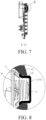
FIG. 7 and FIG. 8 are respectively a sectional view of the touch control module taken along a line C-C inFIG. 6 and an enlarged view of a part D. - A home appliance is usually provided with a human-machine interaction component, such as a touch control panel. A user may control an operation of the home appliance by using the touch control panel.
-
FIG. 1 is an exploded view of components of atouch control panel 1.FIG. 2 is a front view of the components of thetouch control panel 1 after fitting. As shown inFIG. 1 , thetouch control panel 1 includes afront cover plate 2, a supportingportion 3, and atouch control module 4. An opening is provided on the supportingportion 3. Thetouch control module 4 is arranged at the opening of the supportingportion 3 and abuts against thefront cover plate 2. - The
touch control panel 1 further includes arear cover plate 5, which may be connected to the supportingportion 3 and can abut against thetouch control module 4, so that a side of thetouch control module 4 facing thefront cover plate 2 is more snugly attached to the front cover plate. - The
front cover plate 2, thetouch control module 4, and therear cover plate 5 may be arranged on the supportingportion 3, and then the assembly of the components may be fitted to the home appliance as a whole. - As shown in
FIG. 2 , thefront cover plate 2 is provided with amain body portion 20. Themain body portion 20 is provided with touchkey regions 21. A user may perform operations by touching indicator patterns corresponding to the touchkey regions 21 or by touchingcorresponding touch keys 44. Functions of thetouch keys 44 are implemented by using thetouch control module 4. - In an embodiment, the
front cover plate 2 may be made of glass or plastic. Preferably, a pattern of the touchkey regions 21 may be provided on a side of thefront cover plate 2 facing thetouch control module 4, to prevent the pattern being worn after long-term use. - As shown in
FIG. 1 , thetouch control module 4 may be provided with thetouch keys 44, which are configured to detect a touch of a user. Thetouch control module 4 may be further provided with a display assembly, which is configured to display content of an interface of the touch control panel, and may be further configured to display corresponding content based on a detected signal indicating that thetouch keys 44 are operated. - Specifically,
FIG. 5 is an exploded view of thetouch control module 4. In a stacking order of the components, thetouch control module 4 sequentially includes acircuit module 40, asupport 42, and adisplay film 43 from rear to front. Thecircuit module 40 and thedisplay film 43 are respectively arranged on two sides of thesupport 42. Thesupport 42 includeslight guide portions 421. Thedisplay film 43 is arranged on thesupport 42 and covers thelight guide portions 421. - In some embodiments, the
circuit module 40 may be provided with lighting lamps such as LED lights to realize backlight. Positions on the support corresponding to the lighting lamps are provided with thelight guide portions 421, so that light can be irradiated to thedisplay film 43 through thelight guide portions 421. - In some embodiments, the
circuit module 40 may be further provided withelastic conductors 41. Theelastic conductors 41 can abut against thefront cover plate 2, and are in a one-to-one correspondence with the touchkey regions 21. A quantity of theelastic conductors 41 may be set according to a quantity of required touch keys. - Generally, the
elastic conductors 41 may be springs or elastic pieces of a specific shape. - In an embodiment, the
touch control module 4 further includesisolation members 5. Generally, theisolation members 5 are arranged between theelastic conductors 41 and thefront cover plate 2, to isolate a non-safety extra-low voltage, that is, thecircuit module 40, to meet a safety requirement. The isolation members are generally made of plastic. - Specifically, according to relevant regulations in the "General Safety Standards for Home Appliances", components in contact with an electrified component need to pass a ball pressure test. However, the
front cover plate 2 usually cannot meet the requirement. Therefore, theisolation members 5 are arranged between theelastic conductors 41 and thefront cover plate 2, to prevent thefront cover plate 2 from failing the ball pressure test. In addition, since plastic is softer than metal and has a smooth surface, the front cover plate can be protected, thereby preventing the front cove plate from being scratched and preventing an appearance of the touch control panel from being affected during fitting. - In an embodiment, the
support 42 is configured with positioning portions 420. Arrangement positions of the positioning portions 420 may correspond to the touchkey regions 21 of thefront cover plate 2. For example, the positioning portions 420 may be a hole structure on thesupport 42. - In an embodiment, for fitting convenience of the
isolation members 5 and stability of the isolation members after fitting, theisolation members 5 may be arranged on the positioning portions 420 of thesupport 42, and ends of theelastic conductors 41 abut against theisolation members 5. Theisolation members 5 are provided with limitingportions 51, so that theisolation members 5 can be limited to the positioning portions 420. In addition, theisolation members 5 are embedded in thesupport 42 of thetouch control module 4, to facilitate subsequent transportation and fitting of thetouch control module 4. -
FIG. 6 to FIG. 8 are schematic diagrams of components of thetouch control module 4 after fitting.FIG. 8 is an enlarged sectional view in which theisolation members 5 are fitted to the positioning portions 420. As shown in the figure, theisolation members 5 are fitted to the positioning portions 420, and theelastic conductors 41 can extend into the positioning portions 420 and abut against inner surface of theisolation members 5. In addition, under an action of theelastic conductors 41, the limitingportions 51 of theisolation members 5 abut against the positioning portions 420, to limit theisolation members 5 to the positioning portions 420. - In an embodiment, the
isolation members 5, although limited to the positioning portions 420, can move in a direction perpendicular to thefront cover plate 2. In this way, after thefront cover plate 2 is fitted to thetouch control module 4, theisolation members 5 can come into seamless contact with thefront cover plate 2 without causing excessive squeeze that damages the front cover plate. - In this embodiment, the support hole structure is provided on the touch control module, the isolation members are embedded therein in a free state, and the isolation members are limited to the support through an elastic compression force of the elastic conductors. In this solution, the isolation members not only can be limited to the support without separation, but also can elastically expand and contract in an axial direction of the positioning portions within a specific range.
- In an embodiment, the
isolation members 5 may have a plurality of configurations enabling the isolation members to be limited to the positioning portions 420. - As shown in
FIG. 4 andFIG. 8 , theisolation members 5 may includeisolation portions 50. Theisolation portions 50 are substantially parallel to thefront cover plate 2. The isolation members further includewalls 52 arranged on theisolation portions 50 and extending in an axial direction of theelastic conductors 41. The limitingportions 51 can extend radially outwards from thewalls 52. - Preferably, the
isolation members 5 may be constructed in the shape of a hat, and the limitingportions 51 are of a brim structure extending radially outwards from edges of theisolation members 5. - The
walls 52 of theisolation members 5 may be peripheral walls arranged on theisolation portions 50. The peripheral walls may surround theelastic conductors 41 in a circumferential direction. The walls may be constructed to include walls distributed on theisolation portions 50 at intervals. The limitingportions 51 may include a plurality of protrusions, and the protrusions are distributed on thewalls 52. - The
isolation members 5 may alternatively be constructed to include a plurality of claw portions distributed on theisolation portions 50. The limitingportions 51 are constructed as structures extending radially outwards from end portions of the claw portions. - The foregoing epitaxial structure, the brim structure, and the protrusion structures can provide a limiting function. For example, since the
elastic conductors 41 abut against theisolation members 5, the isolation members are limited to the positioning portions 420 by the limiting structures, thereby preventing the isolation members from being separated from the positioning portions. - In an embodiment, the
support 42 includes a surface facing thefront cover plate 2. After thecircuit module 40 is fitted to thesupport 42, under an action of theelastic conductors 41, theisolation members 5 can at least partially extend out of the surface by a specific height. Preferably, the height is 2 mm. In this way, the protruding height enables a protruding surface to be in full contact with the front cover plate after thetouch control module 4 is fitted to the front cover plate, thereby ensuring seamless contact. In addition, the isolation members are prevented from generating excessive squeeze that damages the front cover plate. - In an embodiment, gaps are formed radially between the
isolation members 5 and the positioning portions 420. The gaps need to be formed within a proper range, to ensure that the isolation members can move flexibly, and prevent problems that lead to poor contact such as jamming and tilting. - In an embodiment, the
isolation members 5 are made of plastic, and a thickness of the isolation members in an axial direction is in a range of 0.7 mm to 1.0 mm. Since a principle of the touch keys is to detect a capacitance change in a region when a user touches the keys, to realize effective touch of the touch keys, the thickness of the isolation members arranged between the front cover plate and the elastic conductors cannot be excessively large. This preferred embodiment can meet strength requirements on the isolation members while ensuring that a corresponding touch signal can be detected by the touch key. -
FIG. 2 to FIG. 4 are schematic diagrams of the front cover plate and the touch control module after fitting. In an actual fitting process, the assembly of thetouch control module 4 and thefront cover plate 2 may be arranged on the supportingportion 3. Since the isolation members can at least partially extend out of a surface of the support by a specific height under the support of the elastic conductors, outer surfaces of the isolation members can abut against the front cover plate, thereby limiting the isolation members to the positioning portions. As shown inFIG. 4 , after the front cover plate is fitted to thetouch control module 4, the isolation members are squeezed by the front cover plate, and therefore retract towards the circuit module by a stroke. An additional isolation member structure is added between the elastic conductors and the front cover plate, and a stroke and a position thereof are limited by using the support, so that the fitted structure is more stable. In addition, it is ensured that the isolation members can keep close contact to provide a trigger function. - In this embodiment, the isolation members are embedded in the positioning portions in a free state by using the elastic conductor. Therefore, when the touch control module is subsequently fitted to the front cover plate, the isolation members can be maintained in close contact with the front cover plate, without affecting detection sensitivity of a touch key.
- Although the utility model is disclosed as above, the utility model is not limited thereto. Various alterations and modifications may be made by a person skilled in the art without departing from the spirit and scope of the utility model, and therefore the protection scope of the utility model should be subject to the scope defined by the claims.
Claims (16)
- A touch control module, characterized by comprising:a circuit module (40), provided with a first surface, wherein the first surface is provided with elastic conductors (41); anda support (42), arranged on the first surface of the circuit module (40), wherein positioning portions (420) corresponding to the elastic conductors (41) are provided on the support (42); andthe touch control module further comprises isolation members (5), wherein the isolation members (5) are provided with limiting portions (51), the isolation members (5) are arranged on the positioning portions (420), the elastic conductors (41) at least partially extend into the positioning portions (420) and abut against inner surfaces of the isolation members (5), and the limiting portions (51) abut against edges of the positioning portions (420) to limit the isolation members (5) to the positioning portions (420).
- The touch control module according to claim 1, characterized in that the isolation members (5) are movably arranged on the positioning portions (420) in a direction perpendicular to a front cover plate (2).
- The touch control module according to claim 1, characterized in that the isolation members (5) further comprise walls (52) extending in an axial direction of the elastic conductors (41), and the limiting portions (51) extend radially outwards from the walls (52).
- The touch control module according to claim 3, characterized in that the isolation members (5) are formed in the shape of a hat, and the limiting portions (51) are of a brim structure extending radially outwards from edges of the isolation members (5).
- The touch control module according to claim 3, characterized in that the limiting portions (51) comprise a plurality of protrusions, and the protrusions are distributed on the walls (52).
- The touch control module according to claim 1, characterized in that the positioning portions (420) are of a through hole structure formed on the support (42).
- The touch control module according to claim 1, characterized in that the support (42) comprises a surface facing away from the circuit module (40), and after the circuit module (40) is fitted to the support (42), under an action of the elastic conductors (41), the isolation members (5) at least partially extend out of the surface by a specific height.
- The touch control module according to claim 7, characterized in that the height is 2 mm.
- The touch control module according to claim 1, characterized in that gaps are formed radially between the isolation members (5) and the positioning portions (420).
- The touch control module according to any one of claims 1 to 9, characterized in that a thickness of the isolation members (5) in an axial direction is in a range of 0.7 mm to 1.0 mm.
- The touch control module according to any one of claims 1 to 9, characterized in that the isolation members (5) are made of plastic.
- The touch control module according to claim 1, characterized by further comprising a display film (43), wherein the support (42) comprises light guide portions (421), and the display film (43) is arranged on a side of the support (42) close to a front cover plate (2) and covers the light guide portions (421).
- A touch control panel, characterized by comprising a front cover plate and the touch control module according to any one of claims 1 to 12, wherein the front cover plate (2) is arranged on a side of the support (42) away from the circuit module (40), and abuts against the isolation members (5).
- The touch control panel according to claim 13, characterized in that the front cover plate (2) comprises a main body portion (20), and the main body portion (20) is provided with touch key regions (21) corresponding to the elastic conductors (41).
- The touch control panel according to claim 13, characterized by further comprising a supporting portion (3), wherein the touch control module is arranged on the supporting portion (3).
- A home appliance, characterized by comprising the touch control panel according to any one of claims 13 to 15.
Applications Claiming Priority (1)
| Application Number | Priority Date | Filing Date | Title |
|---|---|---|---|
| CN202320981486.6U CN220438902U (en) | 2023-04-26 | 2023-04-26 | Touch modules, touch panels and home appliances |
Publications (2)
| Publication Number | Publication Date |
|---|---|
| EP4456426A1 true EP4456426A1 (en) | 2024-10-30 |
| EP4456426B1 EP4456426B1 (en) | 2026-05-06 |
Family
ID=89703071
Family Applications (1)
| Application Number | Title | Priority Date | Filing Date |
|---|---|---|---|
| EP24166339.2A Active EP4456426B1 (en) | 2023-04-26 | 2024-03-26 | Touch control module, touch control panel and home appliance thereof |
Country Status (3)
| Country | Link |
|---|---|
| US (1) | US12530094B2 (en) |
| EP (1) | EP4456426B1 (en) |
| CN (1) | CN220438902U (en) |
Citations (6)
| Publication number | Priority date | Publication date | Assignee | Title |
|---|---|---|---|---|
| US4293745A (en) * | 1978-06-23 | 1981-10-06 | Toyostar Corporation | Capacitance type contact switch |
| WO2008035838A1 (en) * | 2006-09-21 | 2008-03-27 | Ad Semiconductor Co., Ltd. | Switch module of which the brightness and sensitivity are improved |
| EP2045923A1 (en) * | 2007-09-27 | 2009-04-08 | FagorBrandt SAS | Device with lit capacitive touch switch and control keypad comprising such a device |
| DE202014101253U1 (en) * | 2014-03-18 | 2014-05-14 | Ching-Hsiung Chu | switch structure |
| US20170179952A1 (en) * | 2014-04-03 | 2017-06-22 | Micro Motion, Inc. | Capacitive touch sensor |
| DE102018002715A1 (en) * | 2018-04-05 | 2019-10-10 | Diehl Ako Stiftung & Co. Kg | Operating device, in particular for an electronic household appliance |
Family Cites Families (3)
| Publication number | Priority date | Publication date | Assignee | Title |
|---|---|---|---|---|
| DE102011006021A1 (en) * | 2011-03-24 | 2012-09-27 | E.G.O. Elektro-Gerätebau GmbH | Operating device for an electrical appliance |
| DE202013011528U1 (en) * | 2013-08-01 | 2014-11-03 | Diehl Ako Stiftung & Co. Kg | Touch and / or proximity sensitive input device |
| WO2015167734A2 (en) * | 2014-05-02 | 2015-11-05 | Illinois Tool Works Inc. | Modular capacitive touch switch system |
-
2023
- 2023-04-26 CN CN202320981486.6U patent/CN220438902U/en active Active
-
2024
- 2024-03-26 EP EP24166339.2A patent/EP4456426B1/en active Active
- 2024-04-11 US US18/632,986 patent/US12530094B2/en active Active
Patent Citations (6)
| Publication number | Priority date | Publication date | Assignee | Title |
|---|---|---|---|---|
| US4293745A (en) * | 1978-06-23 | 1981-10-06 | Toyostar Corporation | Capacitance type contact switch |
| WO2008035838A1 (en) * | 2006-09-21 | 2008-03-27 | Ad Semiconductor Co., Ltd. | Switch module of which the brightness and sensitivity are improved |
| EP2045923A1 (en) * | 2007-09-27 | 2009-04-08 | FagorBrandt SAS | Device with lit capacitive touch switch and control keypad comprising such a device |
| DE202014101253U1 (en) * | 2014-03-18 | 2014-05-14 | Ching-Hsiung Chu | switch structure |
| US20170179952A1 (en) * | 2014-04-03 | 2017-06-22 | Micro Motion, Inc. | Capacitive touch sensor |
| DE102018002715A1 (en) * | 2018-04-05 | 2019-10-10 | Diehl Ako Stiftung & Co. Kg | Operating device, in particular for an electronic household appliance |
Also Published As
| Publication number | Publication date |
|---|---|
| US12530094B2 (en) | 2026-01-20 |
| US20240361854A1 (en) | 2024-10-31 |
| EP4456426B1 (en) | 2026-05-06 |
| CN220438902U (en) | 2024-02-02 |
Similar Documents
| Publication | Publication Date | Title |
|---|---|---|
| JP3213042U (en) | Key and switch housing for keyboard assembly | |
| EP3399383B1 (en) | Mobile terminal | |
| TWI532067B (en) | Keyboard | |
| WO2016192641A1 (en) | Key device manipulation and control method, key device and terminal | |
| TWM448728U (en) | Backlight module and keyboard | |
| CN206250095U (en) | Key and key structure | |
| US20140190814A1 (en) | Touch input device with button function | |
| US20150193010A1 (en) | Hardware keyboard for display keyboard | |
| EP4456426B1 (en) | Touch control module, touch control panel and home appliance thereof | |
| EP4456427A1 (en) | Touch control panel and houshold appliance | |
| US20170338062A1 (en) | Slim key structure | |
| CN102713801A (en) | Solid state positive force touch sensing | |
| CN218850754U (en) | Touch key board and touch equipment | |
| CN210200601U (en) | Double-layer waterproof key panel structure | |
| KR101767334B1 (en) | Wearable computer mouse | |
| CN201536075U (en) | Low-height multi-direction indication key structure | |
| CN215815613U (en) | Touch display assembly and household appliance | |
| CN209248484U (en) | A kind of novel mouse being convenient for changing keycap | |
| CN106214005B (en) | A kind of non-intrusion type Waterproof key structure of cookware | |
| CN220020200U (en) | Ultra-narrow frame luminous touch pad of notebook computer | |
| CN218607993U (en) | a game machine | |
| CN220798253U (en) | Touch switch with vibration feedback | |
| CN214412697U (en) | Touch induction interactive intelligent guarding card | |
| CN101807481B (en) | Telescopic key device | |
| CN103824715A (en) | Touch control switch panel and touch control switch assembly |
Legal Events
| Date | Code | Title | Description |
|---|---|---|---|
| PUAI | Public reference made under article 153(3) epc to a published international application that has entered the european phase |
Free format text: ORIGINAL CODE: 0009012 |
|
| STAA | Information on the status of an ep patent application or granted ep patent |
Free format text: STATUS: THE APPLICATION HAS BEEN PUBLISHED |
|
| AK | Designated contracting states |
Kind code of ref document: A1 Designated state(s): AL AT BE BG CH CY CZ DE DK EE ES FI FR GB GR HR HU IE IS IT LI LT LU LV MC ME MK MT NL NO PL PT RO RS SE SI SK SM TR |
|
| STAA | Information on the status of an ep patent application or granted ep patent |
Free format text: STATUS: REQUEST FOR EXAMINATION WAS MADE |
|
| 17P | Request for examination filed |
Effective date: 20250430 |
|
| GRAP | Despatch of communication of intention to grant a patent |
Free format text: ORIGINAL CODE: EPIDOSNIGR1 |
|
| STAA | Information on the status of an ep patent application or granted ep patent |
Free format text: STATUS: GRANT OF PATENT IS INTENDED |
|
| RIC1 | Information provided on ipc code assigned before grant |
Ipc: H03K 17/96 20060101AFI20251029BHEP |
|
| INTG | Intention to grant announced |
Effective date: 20251126 |
|
| RIN1 | Information on inventor provided before grant (corrected) |
Inventor name: ZOU, QINGQIANG Inventor name: ZANG, MING Inventor name: BAI, XUEMEI Inventor name: LI, JUN |
|
| GRAS | Grant fee paid |
Free format text: ORIGINAL CODE: EPIDOSNIGR3 |
|
| GRAA | (expected) grant |
Free format text: ORIGINAL CODE: 0009210 |
|
| STAA | Information on the status of an ep patent application or granted ep patent |
Free format text: STATUS: THE PATENT HAS BEEN GRANTED |
|
| AK | Designated contracting states |
Kind code of ref document: B1 Designated state(s): AL AT BE BG CH CY CZ DE DK EE ES FI FR GB GR HR HU IE IS IT LI LT LU LV MC ME MK MT NL NO PL PT RO RS SE SI SK SM TR |
|
| REG | Reference to a national code |
Ref country code: CH Ref legal event code: F10 Free format text: ST27 STATUS EVENT CODE: U-0-0-F10-F00 (AS PROVIDED BY THE NATIONAL OFFICE) Effective date: 20260506 Ref country code: GB Ref legal event code: FG4D |