EP4456412A1 - Detection method and apparatus for motor parameters - Google Patents
Detection method and apparatus for motor parameters Download PDFInfo
- Publication number
- EP4456412A1 EP4456412A1 EP24171760.2A EP24171760A EP4456412A1 EP 4456412 A1 EP4456412 A1 EP 4456412A1 EP 24171760 A EP24171760 A EP 24171760A EP 4456412 A1 EP4456412 A1 EP 4456412A1
- Authority
- EP
- European Patent Office
- Prior art keywords
- axis
- signal
- axis voltage
- rated
- current
- Prior art date
- Legal status (The legal status is an assumption and is not a legal conclusion. Google has not performed a legal analysis and makes no representation as to the accuracy of the status listed.)
- Pending
Links
Images



Classifications
-
- H—ELECTRICITY
- H02—GENERATION; CONVERSION OR DISTRIBUTION OF ELECTRIC POWER
- H02P—CONTROL OR REGULATION OF ELECTRIC MOTORS, ELECTRIC GENERATORS OR DYNAMO-ELECTRIC CONVERTERS; CONTROLLING TRANSFORMERS, REACTORS OR CHOKE COILS
- H02P23/00—Arrangements or methods for the control of AC motors characterised by a control method other than vector control
- H02P23/14—Estimation or adaptation of motor parameters, e.g. rotor time constant, flux, speed, current or voltage
-
- H—ELECTRICITY
- H02—GENERATION; CONVERSION OR DISTRIBUTION OF ELECTRIC POWER
- H02P—CONTROL OR REGULATION OF ELECTRIC MOTORS, ELECTRIC GENERATORS OR DYNAMO-ELECTRIC CONVERTERS; CONTROLLING TRANSFORMERS, REACTORS OR CHOKE COILS
- H02P21/00—Arrangements or methods for the control of electric machines by vector control, e.g. by control of field orientation
- H02P21/14—Estimation or adaptation of machine parameters, e.g. flux, current or voltage
- H02P21/141—Flux estimation
-
- G—PHYSICS
- G01—MEASURING; TESTING
- G01R—MEASURING ELECTRIC VARIABLES; MEASURING MAGNETIC VARIABLES
- G01R31/00—Arrangements for testing electric properties; Arrangements for locating electric faults; Arrangements for electrical testing characterised by what is being tested not provided for elsewhere
- G01R31/34—Testing dynamo-electric machines
- G01R31/343—Testing dynamo-electric machines in operation
-
- H—ELECTRICITY
- H02—GENERATION; CONVERSION OR DISTRIBUTION OF ELECTRIC POWER
- H02P—CONTROL OR REGULATION OF ELECTRIC MOTORS, ELECTRIC GENERATORS OR DYNAMO-ELECTRIC CONVERTERS; CONTROLLING TRANSFORMERS, REACTORS OR CHOKE COILS
- H02P21/00—Arrangements or methods for the control of electric machines by vector control, e.g. by control of field orientation
- H02P21/14—Estimation or adaptation of machine parameters, e.g. flux, current or voltage
- H02P21/16—Estimation of constants, e.g. the rotor time constant
-
- H—ELECTRICITY
- H02—GENERATION; CONVERSION OR DISTRIBUTION OF ELECTRIC POWER
- H02P—CONTROL OR REGULATION OF ELECTRIC MOTORS, ELECTRIC GENERATORS OR DYNAMO-ELECTRIC CONVERTERS; CONTROLLING TRANSFORMERS, REACTORS OR CHOKE COILS
- H02P21/00—Arrangements or methods for the control of electric machines by vector control, e.g. by control of field orientation
- H02P21/22—Current control, e.g. using a current control loop
-
- H—ELECTRICITY
- H02—GENERATION; CONVERSION OR DISTRIBUTION OF ELECTRIC POWER
- H02P—CONTROL OR REGULATION OF ELECTRIC MOTORS, ELECTRIC GENERATORS OR DYNAMO-ELECTRIC CONVERTERS; CONTROLLING TRANSFORMERS, REACTORS OR CHOKE COILS
- H02P23/00—Arrangements or methods for the control of AC motors characterised by a control method other than vector control
- H02P23/10—Controlling by adding a DC current
-
- H—ELECTRICITY
- H02—GENERATION; CONVERSION OR DISTRIBUTION OF ELECTRIC POWER
- H02P—CONTROL OR REGULATION OF ELECTRIC MOTORS, ELECTRIC GENERATORS OR DYNAMO-ELECTRIC CONVERTERS; CONTROLLING TRANSFORMERS, REACTORS OR CHOKE COILS
- H02P25/00—Arrangements or methods for the control of AC motors characterised by the kind of AC motor or by structural details
- H02P25/02—Arrangements or methods for the control of AC motors characterised by the kind of AC motor or by structural details characterised by the kind of motor
- H02P25/022—Synchronous motors
- H02P25/024—Synchronous motors controlled by supply frequency
Definitions
- the present application relates to the field of motor parameter detection, and more specifically, to a method for detecting motor parameters, an apparatus for detecting motor parameters, a computer program product, and an air-conditioning compressor system.
- the motor used in the inverter air conditioner industry is a permanent magnet synchronous motor (referred to as PMSM), and the control algorithm of the permanent magnet synchronous motor is generally a vector control algorithm, that is, a field-oriented control algorithm (referred to as FOC).
- the vector control algorithm can be composed of coordinate transformation, current sampling and reconstruction, position estimation, speed loop regulator, current loop regulator, and space vector modulation (SVPWM for short), for example.
- a method for detecting motor parameters comprises: injecting a first direct current signal; receiving a first d-q axis feedback current corresponding to the first direct current signal and a first d-q axis voltage output by a current regulation module; injecting a second direct current signal different from the first direct current signal; receiving a second d-q axis feedback current corresponding to the second direct current signal and a second d-q axis voltage output by the current regulation module; and determining motor parameters based on the first d-q axis feedback current, the first d-q axis voltage, the second d-q axis feedback current and the second d-q axis voltage.
- the motor is a permanent magnet synchronous motor and the current regulation module is a PI controller.
- both the first direct current signal and the second direct current signal are positive currents on the d-axis.
- the above method also comprises: injecting a third signal, the third signal being a sinusoidal signal with a certain frequency and amplitude applied on the d-axis; receiving a third d-axis voltage output by the current regulation module, the third d-axis voltage being corresponding to the third signal; and determining a d-axis inductance L d according to the third d-axis voltage.
- an apparatus for detecting motor parameters comprises: a first receiving device for receiving a first d-q axis feedback current corresponding to an injected first direct current signal and a first d-q axis voltage output by a current regulation module; a second receiving device for receiving a second d-q axis feedback current corresponding to an injected second direct current signal and a second d-q axis voltage output by the current regulation module; and a determining device for determining the motor parameters based on the first d-q axis feedback current, the first d-q axis voltage, the second d-q axis feedback current and the second d-q axis voltage.
- the apparatus may be termed a motor parameter detection apparatus.
- the apparatus may be configured to detect motor parameters.
- the motor is a permanent magnet synchronous motor and the current regulation module is a PI controller, and both the first direct current signal and the second direct current signal are positive currents on the d-axis.
- the motor parameters include permanent magnet flux linkage ⁇ m
- the above apparatus further comprises: a third receiving device for receiving a third d-axis voltage output by the current regulation module, the third d-axis voltage being corresponding to the third signal which is a sinusoidal signal with a certain frequency and amplitude applied on the d-axis; and the determining device is also configured to determine a d-axis inductance L d according to the third d-axis voltage.
- a computer program product comprising a computer program
- the method according to the first aspect of the invention optionally including any of the optional features described above is implemented.
- an air-conditioning compressor system comprising a permanent magnet synchronous motor; and the apparatus according to the second aspect of the invention optionally including any of the optional features described above, for detecting motor parameters of the permanent magnet synchronous motor.
- the detection scheme of the motor parameters is implemented by receiving the first d-q axis feedback current corresponding to the injected first direct current signal and the first d-q axis voltage, the second d-q axis feedback current corresponding to the injected second direct current signal and the second d-q axis voltage and determining motor parameters based on the first d-q axis feedback current, the first d-q axis voltage, the second d-q axis feedback current and the second d-q axis voltage.
- This scheme uses the current closed-loop structure of vector control to avoid the risk of overcurrent, and does not require additional hardware equipment.
- both the first DC signal and the second DC signal are positive currents on the d-axis, which can effectively keep the rotor stationary (making the final measured motor parameters more accurate), and can avoid the risk of PMSM demagnetization.
- FIG. 1 shows a schematic flowchart of a method 1000 for detecting motor parameters according to an embodiment of the present invention. As shown in FIG. 1 , the method 1000 includes the following steps:
- the term “motor” may also be referred to as “electric motor”, which is a device that converts electrical energy into mechanical energy. It uses the energized coil (that is, the stator winding) to generate a rotating magnetic field and acts on the rotor to form a magneto-electric force rotation torque.
- the motor may be a permanent magnet synchronous motor PMSM.
- motor parameters are used to denote parameters related to vector control of the motor.
- the motor parameters include: stator resistance, inductance, and permanent magnet flux linkage.
- step S 110 and step S130 the first direct current signal and the second direct current signal are respectively injected.
- both the first DC signal and the second DC signal are injected into the input side of the current closed-loop control structure of the motor.
- FIG. 3 shows a schematic diagram of signal injection and parameter detection according to an embodiment of the present invention.
- the current closed-loop control structure consists of a first mixer 312, a second mixer 314, a first PI controller 322, a second PI controller 324, a first coordinate system transformation module 330, and a space vector modulation module 340, an inverter module 350, and a second coordinate system transformation module 370.
- i dinj represents the current injection signal of the d-axis
- i qinj represents the current injection signal of the q-axis
- i dinj is applied to the first mixer 312 so as to be mixed with the d-axis feedback current i dfdb output by the second coordinate system transformation module 370; similarly, i qinj is applied to the second mixer 314 to be mixed with the q-axis feedback current i qfdb output by the second coordinate system transformation module 370.
- the injected first/second direct current signal is to be understood as the sum of the d-axis current injection signal and the q-axis current injection signal.
- the "current regulation module” is a PI controller, also known as a proportional-integral controller.
- the current regulation module can also be a PID controller.
- i dinj and i qinj that is, components of the first DC signal on the d-axis and q-axis
- i dinj and i qinj that is, components of the first DC signal on the d-axis and q-axis
- the first PI controller 322 outputting the first d-axis voltage Vd
- the second PI controller 324 outputting the first q-axis voltage Vq
- the second coordinate system transformation module 370 outputting the first d-axis feedback current i dfdb and the first q-axis feedback current i qfdb and supplying them to the first mixer 312 and the second mixer 314 respectively. That is to say, the first d-axis voltage Vd and the first q-axis voltage Vq correspond to the injected first DC signal.
- a second DC signal different from the first DC signal (with different current vector values) is injected into the input terminals of the first mixer 312 and the second mixer 314.
- i dinj and i qinj represent the components of the second DC signal on the d-axis and q-axis
- the first PI controller 322 outputs the second d-axis voltage Vd
- the second PI controller 324 outputs the second q-axis voltage Vq
- the second coordinate system transformation module 370 outputs the second d-axis feedback current i dfdb and the second q-axis feedback current i qfdb , and provides them to the first mixer 312 and the second mixer 314 respectively. That is to say, the second d-axis voltage Vd and the second q-axis voltage Vq correspond to the injected second direct current signal.
- both the first direct current signal and the second direct current signal are positive currents on the d-axis. That is to say, the component of the first DC signal and the second DC signal on the d-axis is positive DC, while the component on the q-axis is 0. This can effectively keep the rotor stationary (making the finally measured motor parameters more accurate), and can avoid the risk of demagnetization of the permanent magnet synchronous motor 360.
- step S150 motor parameters are determined based on the received first d-q axis feedback current, first d-q axis voltage, second d-q axis feedback current and second d-q axis voltage.
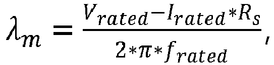
- V rated is a rated (working) voltage of the permanent magnet synchronous motor
- I rated is a rated current of the permanent magnet synchronous motor
- f rated is a rated frequency of the permanent magnet synchronous motor.
- the rated voltage, rated current and rated frequency of the permanent magnet synchronous motor are all known quantities, for example, can be obtained from the nameplate of the permanent magnet synchronous motor.
- the method 1000 may further include: injecting a third signal, the third signal is a sinusoidal signal with a certain frequency and amplitude applied on the d-axis; receiving a third d-axis voltage output by the current regulation module, the third d-axis voltage corresponding to the third signal; and determining a d-axis inductance L d according to the third d-axis voltage.
- the frequency is 400-600Hz, and this value range is a good balance between the detection accuracy of the motor parameters and the detection requirements of the digital controller----on the one hand, the frequency is much higher than the mechanical frequency (need to be as high as possible to avoid rotor rotation); on the other hand, the frequency takes into account the detection needs of the digital controller (in order to effectively restore the sine wave, the frequency cannot be too high).
- the third signal is also injected into the input side of the current closed-loop control structure of the motor. Since the third signal is only applied on the d-axis, its component on the q-axis is 0. For example, the d-axis component i dinj injected into the first mixer 312 is equal to i hd , while the i qinj injected into the input terminal of the second mixer 314 is 0.
- a third signal is injected into the input terminals of the first mixer 312 and the second mixer 314 (wherein, i dinj is equal to i hd , i qinj is equal to 0), thus the first PI controller 322 outputs the third d-axis voltage V d , the second PI controller 324 outputs the third q-axis voltage V q , and the second coordinate system transformation module 370 outputs the third d-axis feedback current i dfdb and the third q-axis feedback current i qfdb and provides them to the first mixer 312 and the second mixer 314 respectively. That is, the third d-axis voltage V d corresponds to the injected third signal.
- the method 1000 further includes: injecting a fourth signal, the fourth signal is a sinusoidal signal with a certain frequency and amplitude applied on the q-axis; receiving the fourth q-axis voltage output by the current regulation module, which corresponds to the fourth signal; and determining the q-axis inductance L q according to the fourth q-axis voltage.
- the frequency is 400-600Hz, and this value range is a good balance between the detection accuracy of the motor parameters and the detection requirements of the digital controller----on the one hand, the frequency is much higher than the mechanical frequency (the frequency needs to be as high as possible to avoid rotor rotation); on the other hand, the frequency takes into account the detection needs of the digital controller (in order to effectively restore the sine wave, the frequency cannot be too high).
- the fourth signal is also injected into the input side of the current closed-loop control structure of the motor. Since the fourth signal is only applied on the q-axis, its component on the d-axis is 0. For example, the d-axis component i dinj injected into the first mixer 312 is equal to 0, while the i qinj injected into the input terminal of the second mixer 314 is i hq .
- a fourth signal is injected into the input terminals of the first mixer 312 and the second mixer 314 (wherein, i dinj is equal to 0, i qinj is equal to i hq ), thus the first PI controller 322 outputs the fourth d-axis voltage V d , the second PI controller 324 outputs the fourth q-axis voltage V q , and the second coordinate system transformation module 370 outputs the fourth d-axis feedback current i dfdb and the fourth q-axis feedback current i qfdb and provides them to the first mixer 312 and the second mixer 314 respectively. That is, the fourth q-axis voltage V q corresponds to the injected fourth signal.
- FIG. 4 shows a waveform diagram of signals injected into the d-q axis according to an embodiment of the present invention, wherein the first DC signal, the second DC signal, the third signal and the fourth signal are injected onto the d-q axis in sequence.
- reference numeral 412 represents the component of the injected current signal on the d-axis, namely i dinj
- reference numeral 414 represents the component of the injected current signal on the q-axis, namely i qinj
- reference numeral 440 shows an enlarged view of the component on the d-axis and the component on the q-axis of the injected current signal framed by the dotted box 430. It can be seen from the enlarged part that a sine wave (i.e., the third signal) is first injected on the d-axis, and then a sine wave (i.e., the fourth signal) is injected on the q-axis.
- a sine wave i.e., the third signal
- the method 1000 provided by the foregoing one or more embodiments of the present invention can be implemented by a computer program.
- the computer program is included in a computer program product, and when the computer program is executed by a processor, the method 1000 for detecting motor parameters of one or more embodiments of the present invention is implemented.
- the computer storage medium such as a USB flash drive
- running the computer program can execute the method (1000) for detecting motor parameters of one or more embodiments of the present invention.
- FIG. 2 shows a schematic structural diagram of an apparatus for detecting motor parameters 2000 according to an embodiment of the present invention.
- the apparatus 2000 includes: a first receiving device 210, a second receiving device 220, and a determining device 230, wherein the first receiving device 210 is used for receiving a first d-q axis feedback current corresponding to an injected first direct current signal and a first d-q axis voltage output by a current regulation module; the second receiving device 220 is used for receiving a second d-q axis feedback current corresponding to an injected second direct current signal and a second d-q axis voltage output by the current regulation module; and the determining device 230 is used for determining the motor parameters based on the first d-q axis feedback current, the first d-q axis voltage, the second d-q axis feedback current and the second d-q axis voltage.
- the motor is a permanent magnet synchronous motor PMSM
- the current regulation module is a PI controller
- both the first DC signal and the second DC signal are positive currents on the d-axis.
- the motor 360 is a permanent magnet synchronous motor PMSM, and an apparatus for detecting motor parameters is denoted by reference numeral 380.
- the detection apparatus 380 receives the output d-axis feedback current i dfdb and q-axis feedback current i qfdb from the second coordinate system transformation module 370, and also receives the d-axis voltage V d from the first PI controller 322, receives the q-axis voltage V q from the second PI controller 324, and then obtain one or more motor parameters.
- the motor parameters include stator resistance R s .
- the apparatus 2000 may further include: a third receiving device for receiving the third d-axis voltage output by the current regulation module, the third d-axis voltage corresponding to the injected third signal, and the third signal is a sinusoidal signal with a certain frequency and amplitude applied on the d-axis.
- the determining device 230 is further configured to determine a d-axis inductance L d according to the third d-axis voltage.
- the apparatus 2000 further includes: a fourth receiving device for receiving a fourth q-axis voltage output by the current regulation module, the fourth q-axis voltage being corresponding to an injected fourth signal which is a sinusoidal signal with a certain frequency and amplitude applied on the q-axis; and the determining device 230 is further configured to determine the q-axis inductance L q according to the fourth q-axis voltage.
- the above apparatus for detecting motor parameters 2000 can be applied to various motor systems, including but not limited to air conditioner compressor systems.
- the air conditioner compressor system includes: a permanent magnet synchronous motor; and an apparatus for detecting motor parameters 2000, wherein the apparatus 2000 is used for detecting the motor parameters of the permanent magnet synchronous motor.
- a number of motor parameter calculation formulas are provided.
- these calculation formulas can be derived based on the d-q axis equivalent circuit model of the permanent magnet synchronous motor as shown in FIG. 5 .
- the circuit diagram of the left half shows the equivalent circuit of the d-axis
- the circuit diagram of the right half shows the equivalent circuit of the q-axis.
- the stator resistance R s is coupled in series with the counter electromotive force ⁇ ⁇ qs r and the leakage inductance L ls .
- the stator resistance R s is coupled in series with the counter electromotive force ⁇ ⁇ ds r and the leakage inductance L ls .
- the sum of the leakage inductance L ls and the d-axis excitation inductance L md is the d-axis inductance L d .
- the sum of the leakage inductance L ls and the q-axis excitation inductance L mq is the q-axis inductance L q .
Landscapes
- Engineering & Computer Science (AREA)
- Power Engineering (AREA)
- Physics & Mathematics (AREA)
- General Physics & Mathematics (AREA)
- Control Of Ac Motors In General (AREA)
Abstract
A method (1000) for detecting motor parameters, comprises: injecting (110) a first direct current signal; receiving (120) a first d-q axis feedback current corresponding to the first direct current signal and a first d-q axis voltage output by a current regulation module; injecting (130) a second direct current signal different from the first direct current signal; receiving (140) a second d-q axis feedback current corresponding to the second direct current signal and a second d-q axis voltage output by the current regulation module; and determining (150) motor parameters based on the first d-q axis feedback current, the first d-q axis voltage, the second d-q axis feedback current and the second d-q axis voltage. Also disclosed is an apparatus (2000) for detecting motor parameters, a computer program product and an air conditioner compressor system.
Description
- The present application relates to the field of motor parameter detection, and more specifically, to a method for detecting motor parameters, an apparatus for detecting motor parameters, a computer program product, and an air-conditioning compressor system.
- The motor used in the inverter air conditioner industry is a permanent magnet synchronous motor (referred to as PMSM), and the control algorithm of the permanent magnet synchronous motor is generally a vector control algorithm, that is, a field-oriented control algorithm (referred to as FOC). The vector control algorithm can be composed of coordinate transformation, current sampling and reconstruction, position estimation, speed loop regulator, current loop regulator, and space vector modulation (SVPWM for short), for example.
- The accuracy of PMSM parameters will directly determine the performance and stability of vector control. But in most PMSM-driven applications, the motor parameters are unknown and will change with age. The existing motor parameter detection methods need to rotate the rotor and use complex algorithms to detect parameters, which is inconvenient to operate.
- According to a first aspect of the present invention, a method for detecting motor parameters is provided. The method comprises: injecting a first direct current signal; receiving a first d-q axis feedback current corresponding to the first direct current signal and a first d-q axis voltage output by a current regulation module; injecting a second direct current signal different from the first direct current signal; receiving a second d-q axis feedback current corresponding to the second direct current signal and a second d-q axis voltage output by the current regulation module; and determining motor parameters based on the first d-q axis feedback current, the first d-q axis voltage, the second d-q axis feedback current and the second d-q axis voltage.
- Optionally, the motor is a permanent magnet synchronous motor and the current regulation module is a PI controller.
- Optionally, both the first direct current signal and the second direct current signal are positive currents on the d-axis.
- Optionally, the motor parameters include a stator resistance Rs, wherein the stator resistance Rs is determined according to the following formula: Rs =

- Optionally, the motor parameters include permanent magnet flux linkage λm, wherein the permanent magnet flux linkage λm is determined according to the following formula:

- Optionally, the above method also comprises: injecting a third signal, the third signal being a sinusoidal signal with a certain frequency and amplitude applied on the d-axis; receiving a third d-axis voltage output by the current regulation module, the third d-axis voltage being corresponding to the third signal; and determining a d-axis inductance Ld according to the third d-axis voltage.
- Optionally, the third signal is represented by the following formula: ihd = id + i h1sin(2 * π * f h1 * t), wherein ihd is the third signal, id is a DC offset on the d-axis, ih1 is an amplitude of the sinusoidal signal, and fh1 is a frequency of the sinusoidal signal.
- Optionally, the d-axis inductance Ld is determined according to the following formula:

- Optionally, the above method also comprises: injecting a fourth signal, the fourth signal being a sinusoidal signal with a certain frequency and amplitude applied on the q-axis; receiving a fourth q-axis voltage output by the current regulation module, the fourth q-axis voltage being corresponding to the fourth signal; and determining a q-axis inductance Lq according to the fourth q-axis voltage, wherein the fourth signal is represented by the following formula: ihq = i h2sin(2 * π * f h2 * t), wherein ihq is the fourth signal, ih2 is an amplitude of the sinusoidal signal, and fh2 is a frequency of the sinusoidal signal, wherein the q-axis inductance Lq is determined according to the following formula:

- According to a second aspect of the present invention, an apparatus for detecting motor parameters is provided. The apparatus comprises: a first receiving device for receiving a first d-q axis feedback current corresponding to an injected first direct current signal and a first d-q axis voltage output by a current regulation module; a second receiving device for receiving a second d-q axis feedback current corresponding to an injected second direct current signal and a second d-q axis voltage output by the current regulation module; and a determining device for determining the motor parameters based on the first d-q axis feedback current, the first d-q axis voltage, the second d-q axis feedback current and the second d-q axis voltage. The apparatus may be termed a motor parameter detection apparatus. The apparatus may be configured to detect motor parameters.
- Optionally, the motor is a permanent magnet synchronous motor and the current regulation module is a PI controller, and both the first direct current signal and the second direct current signal are positive currents on the d-axis.
- Optionally, the motor parameters include a stator resistance Rs, wherein the determining device is configured to determine the stator resistance Rs according to the following formula:

- Optionally, the motor parameters include permanent magnet flux linkage λm, wherein the determining device is configured to determine the permanent magnet flux linkage λm according to the following formula:

- Optionally, the above apparatus further comprises: a third receiving device for receiving a third d-axis voltage output by the current regulation module, the third d-axis voltage being corresponding to the third signal which is a sinusoidal signal with a certain frequency and amplitude applied on the d-axis; and the determining device is also configured to determine a d-axis inductance Ld according to the third d-axis voltage.
- Optionally, the third signal is represented by the following formula: ihd = id + i h1sin(2 * π * f h1 * t), wherein ihd is the third signal, id is a DC offset on the d-axis, ih1 is an amplitude of the sinusoidal signal, and fh1 is a frequency of the sinusoidal signal, and wherein the determining device is further configured to determine the d-axis inductance Ld according to the following formula:

- Optionally, the above apparatus further comprises: a fourth receiving device for receiving a fourth q-axis voltage output by the current regulation module, the fourth q-axis voltage being corresponding to an injected fourth signal which is a sinusoidal signal with a certain frequency and amplitude applied on the q-axis; and the determining device is further configured to determine a q-axis inductance Lq according to the fourth q-axis voltage, wherein the fourth signal is represented by the following formula: ihq = i h2sin(2 * π * f h2 * t), wherein ihq is the fourth signal, ih2 is an amplitude of the sinusoidal signal, and fh2 is a frequency of the sinusoidal signal, wherein the q-axis inductance Lq is determined according to the following formula: Lq =

- According to another aspect of the present invention, a computer program product comprising a computer program is provided, wherein when the computer program is executed by a processor, the method according to the first aspect of the invention optionally including any of the optional features described above is implemented.
- According to another aspect of the present invention, an air-conditioning compressor system is provided. The system comprises a permanent magnet synchronous motor; and the apparatus according to the second aspect of the invention optionally including any of the optional features described above, for detecting motor parameters of the permanent magnet synchronous motor.
- The above and other objects and advantages of the present invention will be more fully understood from the following detailed description which describes preferred embodiments of the present invention by way of example only and with reference to the accompanying drawings, wherein the same or similar elements are denoted by the same reference numerals.
-
FIG. 1 shows a schematic flow chart of a method for detecting motor parameters; -
FIG. 2 shows a schematic structural diagram of an apparatus for detecting motor parameters; -
FIG. 3 shows a schematic diagram of injecting signals into a system including an apparatus for detecting motor parameters; -
FIG. 4 shows a waveform diagram of a signal injected into the d-q axis; and -
FIG. 5 shows a d-q axis equivalent circuit diagram of a permanent magnet synchronous motor. - The present invention is described more fully hereinafter with reference to the accompanying drawings, in which illustrative embodiments of the invention are shown. However, the present invention may be embodied in different forms, and should not be construed as being limited to only the embodiments given herein. The above-mentioned embodiments are given to make the disclosure herein comprehensive and complete, so as to more fully convey the protection scope of the present invention to those skilled in the art, wherein the scope of the invention is defined by the appended claims.
- In this specification, terms such as "comprising" and "including" mean that in addition to the units and steps that are directly and explicitly stated in the specification and claims, the technical solution of the application does not exclude the situation of other units and steps not directly or explicitly stated.
- Terms such as "first" and "second" do not indicate the sequence of elements in terms of time, space, size, etc., but are only used to distinguish the elements unless otherwise specified.
- According to some embodiments of the present invention, the detection scheme of the motor parameters is implemented by receiving the first d-q axis feedback current corresponding to the injected first direct current signal and the first d-q axis voltage, the second d-q axis feedback current corresponding to the injected second direct current signal and the second d-q axis voltage and determining motor parameters based on the first d-q axis feedback current, the first d-q axis voltage, the second d-q axis feedback current and the second d-q axis voltage. By using two DC signals, the influence of the dead zone (time) of the inverter can be effectively avoided, thereby ensuring the accuracy of the motor parameters. This scheme uses the current closed-loop structure of vector control to avoid the risk of overcurrent, and does not require additional hardware equipment.
- In addition, in some embodiments of the present invention, both the first DC signal and the second DC signal are positive currents on the d-axis, which can effectively keep the rotor stationary (making the final measured motor parameters more accurate), and can avoid the risk of PMSM demagnetization.
- Specific embodiments of the present invention are further described below with reference to the accompanying drawings. It should be noted that, in order to describe the content related to the present invention more clearly, some unnecessary features or circuit elements are not shown in the drawings. However, for those skilled in the art, this omission will not cause difficulty in implementing the technical solution described in the specification of this application.
-
FIG. 1 shows a schematic flowchart of amethod 1000 for detecting motor parameters according to an embodiment of the present invention. As shown inFIG. 1 , themethod 1000 includes the following steps: - in step 110, injecting a first direct current signal;
- in step 120, receiving a first d-q axis feedback current corresponding to the first direct current signal and a first d-q axis voltage output by a current regulation module;
- in step 130, injecting a second direct current signal different from the first direct current signal;
- in
step 140, receiving a second d-q axis feedback current corresponding to the second direct current signal and a second d-q axis voltage output by the current regulation module; and - in
step 150, determining motor parameters based on the first d-q axis feedback current, the first d-q axis voltage, the second d-q axis feedback current and the second d-q axis voltage. - In the context of this application, the term "motor" may also be referred to as "electric motor", which is a device that converts electrical energy into mechanical energy. It uses the energized coil (that is, the stator winding) to generate a rotating magnetic field and acts on the rotor to form a magneto-electric force rotation torque. In one or more embodiments, the motor may be a permanent magnet synchronous motor PMSM.
- The term "motor parameters" is used to denote parameters related to vector control of the motor. In one embodiment, the motor parameters include: stator resistance, inductance, and permanent magnet flux linkage.
- In step S 110 and step S130, the first direct current signal and the second direct current signal are respectively injected. Here, both the first DC signal and the second DC signal are injected into the input side of the current closed-loop control structure of the motor. For example, see
FIG. 3 , which shows a schematic diagram of signal injection and parameter detection according to an embodiment of the present invention. As shown inFIG. 3 , the current closed-loop control structure consists of afirst mixer 312, asecond mixer 314, afirst PI controller 322, asecond PI controller 324, a first coordinatesystem transformation module 330, and a spacevector modulation module 340, aninverter module 350, and a second coordinatesystem transformation module 370. idinj represents the current injection signal of the d-axis, iqinj represents the current injection signal of the q-axis, wherein idinj is applied to thefirst mixer 312 so as to be mixed with the d-axis feedback current idfdb output by the second coordinatesystem transformation module 370; similarly, iqinj is applied to thesecond mixer 314 to be mixed with the q-axis feedback current iqfdb output by the second coordinatesystem transformation module 370. In the context of the present application, the injected first/second direct current signal is to be understood as the sum of the d-axis current injection signal and the q-axis current injection signal. - In one or more embodiments, the "current regulation module" is a PI controller, also known as a proportional-integral controller. Of course, those skilled in the art can understand that the current regulation module can also be a PID controller.
- Referring to
FIG. 3 , in the first time period, idinj and iqinj (that is, components of the first DC signal on the d-axis and q-axis) are respectively injected into the input terminals of thefirst mixer 312 and thesecond mixer 314, thereby thefirst PI controller 322 outputting the first d-axis voltage Vd, thesecond PI controller 324 outputting the first q-axis voltage Vq, and the second coordinatesystem transformation module 370 outputting the first d-axis feedback current idfdb and the first q-axis feedback current iqfdb and supplying them to thefirst mixer 312 and thesecond mixer 314 respectively. That is to say, the first d-axis voltage Vd and the first q-axis voltage Vq correspond to the injected first DC signal. - In the second time period (for example, the second time period is immediately after the first time period), a second DC signal different from the first DC signal (with different current vector values) is injected into the input terminals of the
first mixer 312 and thesecond mixer 314. It should be noted that at this time idinj and iqinj represent the components of the second DC signal on the d-axis and q-axis, so thefirst PI controller 322 outputs the second d-axis voltage Vd, thesecond PI controller 324 outputs the second q-axis voltage Vq, the second coordinatesystem transformation module 370 outputs the second d-axis feedback current idfdb and the second q-axis feedback current iqfdb, and provides them to thefirst mixer 312 and thesecond mixer 314 respectively. That is to say, the second d-axis voltage Vd and the second q-axis voltage Vq correspond to the injected second direct current signal. - In one embodiment, both the first direct current signal and the second direct current signal are positive currents on the d-axis. That is to say, the component of the first DC signal and the second DC signal on the d-axis is positive DC, while the component on the q-axis is 0. This can effectively keep the rotor stationary (making the finally measured motor parameters more accurate), and can avoid the risk of demagnetization of the permanent
magnet synchronous motor 360. - In step S150, motor parameters are determined based on the received first d-q axis feedback current, first d-q axis voltage, second d-q axis feedback current and second d-q axis voltage. In embodiments where both the first DC signal and the second DC signal are positive currents on the d-axis, the motor parameters may include stator resistance Rs, which may be determined, for example, according to the following equation:

- After calculating the stator resistance Rs, in an embodiment, the permanent magnet flux linkage λm can be further calculated, wherein the permanent magnet flux linkage λm can be determined according to the following formula:

- Although not shown in
FIG. 1 , in one embodiment, themethod 1000 may further include: injecting a third signal, the third signal is a sinusoidal signal with a certain frequency and amplitude applied on the d-axis; receiving a third d-axis voltage output by the current regulation module, the third d-axis voltage corresponding to the third signal; and determining a d-axis inductance Ld according to the third d-axis voltage. - In one embodiment, the third signal is represented by the following formula:

- Same as the first DC signal and the second DC signal, the third signal is also injected into the input side of the current closed-loop control structure of the motor. Since the third signal is only applied on the d-axis, its component on the q-axis is 0. For example, the d-axis component idinj injected into the
first mixer 312 is equal to ihd, while the iqinj injected into the input terminal of thesecond mixer 314 is 0. - Continuing to refer to
FIG. 3 , during a third time period (for example, the third time period is immediately after the second time period), a third signal is injected into the input terminals of thefirst mixer 312 and the second mixer 314 (wherein, idinj is equal to ihd, iqinj is equal to 0), thus thefirst PI controller 322 outputs the third d-axis voltage Vd, thesecond PI controller 324 outputs the third q-axis voltage Vq, and the second coordinatesystem transformation module 370 outputs the third d-axis feedback current idfdb and the third q-axis feedback current iqfdb and provides them to thefirst mixer 312 and thesecond mixer 314 respectively. That is, the third d-axis voltage Vd corresponds to the injected third signal. - In this embodiment, the d-axis inductance Ld is determined according to the following formula:

- In one embodiment, the
method 1000 further includes: injecting a fourth signal, the fourth signal is a sinusoidal signal with a certain frequency and amplitude applied on the q-axis; receiving the fourth q-axis voltage output by the current regulation module, which corresponds to the fourth signal; and determining the q-axis inductance Lq according to the fourth q-axis voltage. - In one embodiment, the fourth signal is represented by the following formula:

- Same as the first DC signal and the second DC signal, the fourth signal is also injected into the input side of the current closed-loop control structure of the motor. Since the fourth signal is only applied on the q-axis, its component on the d-axis is 0. For example, the d-axis component idinj injected into the
first mixer 312 is equal to 0, while the iqinj injected into the input terminal of thesecond mixer 314 is ihq. - Continuing to refer to
FIG. 3 , during a fourth time period (for example, the fourth time period is immediately after the third time period), a fourth signal is injected into the input terminals of thefirst mixer 312 and the second mixer 314 (wherein, idinj is equal to 0, iqinj is equal to ihq), thus thefirst PI controller 322 outputs the fourth d-axis voltage Vd, thesecond PI controller 324 outputs the fourth q-axis voltage Vq, and the second coordinatesystem transformation module 370 outputs the fourth d-axis feedback current idfdb and the fourth q-axis feedback current iqfdb and provides them to thefirst mixer 312 and thesecond mixer 314 respectively. That is, the fourth q-axis voltage Vq corresponds to the injected fourth signal. - In this embodiment, the q-axis inductance Lq is determined according to the following formula:

-
FIG. 4 shows a waveform diagram of signals injected into the d-q axis according to an embodiment of the present invention, wherein the first DC signal, the second DC signal, the third signal and the fourth signal are injected onto the d-q axis in sequence. As shown inFIG. 4 ,reference numeral 412 represents the component of the injected current signal on the d-axis, namely idinj, andreference numeral 414 represents the component of the injected current signal on the q-axis, namely iqinj. InFIG. 4 ,reference numeral 440 shows an enlarged view of the component on the d-axis and the component on the q-axis of the injected current signal framed by the dottedbox 430. It can be seen from the enlarged part that a sine wave (i.e., the third signal) is first injected on the d-axis, and then a sine wave (i.e., the fourth signal) is injected on the q-axis. - In addition, those skilled in the art can easily understand that the
method 1000 provided by the foregoing one or more embodiments of the present invention can be implemented by a computer program. For example, the computer program is included in a computer program product, and when the computer program is executed by a processor, themethod 1000 for detecting motor parameters of one or more embodiments of the present invention is implemented. For another example, when the computer storage medium (such as a USB flash drive) storing the computer program is connected to the computer, running the computer program can execute the method (1000) for detecting motor parameters of one or more embodiments of the present invention. -
FIG. 2 shows a schematic structural diagram of an apparatus for detectingmotor parameters 2000 according to an embodiment of the present invention. As shown inFIG. 2 , theapparatus 2000 includes: afirst receiving device 210, asecond receiving device 220, and a determining device 230, wherein thefirst receiving device 210 is used for receiving a first d-q axis feedback current corresponding to an injected first direct current signal and a first d-q axis voltage output by a current regulation module; thesecond receiving device 220 is used for receiving a second d-q axis feedback current corresponding to an injected second direct current signal and a second d-q axis voltage output by the current regulation module; and the determining device 230 is used for determining the motor parameters based on the first d-q axis feedback current, the first d-q axis voltage, the second d-q axis feedback current and the second d-q axis voltage. - In one embodiment, the motor is a permanent magnet synchronous motor PMSM, the current regulation module is a PI controller, and both the first DC signal and the second DC signal are positive currents on the d-axis.
- For example, continuing to refer to
FIG. 3 , themotor 360 is a permanent magnet synchronous motor PMSM, and an apparatus for detecting motor parameters is denoted byreference numeral 380. Thedetection apparatus 380 receives the output d-axis feedback current idfdb and q-axis feedback current iqfdb from the second coordinatesystem transformation module 370, and also receives the d-axis voltage Vd from thefirst PI controller 322, receives the q-axis voltage Vq from thesecond PI controller 324, and then obtain one or more motor parameters. - In one embodiment, the motor parameters include stator resistance Rs. In this embodiment, the determining device 230 is configured to determine the stator resistance Rs according to the following equation:

- In an embodiment, the motor parameters include the permanent magnet flux linkage λm and the determining device 230 is configured to determine the permanent magnet flux linkage λm according to the following formula:
- Although not shown in
FIG. 2 , in one embodiment, theapparatus 2000 may further include: a third receiving device for receiving the third d-axis voltage output by the current regulation module, the third d-axis voltage corresponding to the injected third signal, and the third signal is a sinusoidal signal with a certain frequency and amplitude applied on the d-axis. The determining device 230 is further configured to determine a d-axis inductance Ld according to the third d-axis voltage. - In one embodiment, the third signal is represented by the following formula:

- In this way, the determining device 230 is configured to determine the d-axis inductance Ld according to the following formula:

- In one embodiment, the
apparatus 2000 further includes: a fourth receiving device for receiving a fourth q-axis voltage output by the current regulation module, the fourth q-axis voltage being corresponding to an injected fourth signal which is a sinusoidal signal with a certain frequency and amplitude applied on the q-axis; and the determining device 230 is further configured to determine the q-axis inductance Lq according to the fourth q-axis voltage. - In one embodiment, the fourth signal is represented by the following formula:


- The above apparatus for detecting
motor parameters 2000 can be applied to various motor systems, including but not limited to air conditioner compressor systems. In one embodiment, the air conditioner compressor system includes: a permanent magnet synchronous motor; and an apparatus for detectingmotor parameters 2000, wherein theapparatus 2000 is used for detecting the motor parameters of the permanent magnet synchronous motor. - In the context of this application, a number of motor parameter calculation formulas are provided. In one or more embodiments, these calculation formulas can be derived based on the d-q axis equivalent circuit model of the permanent magnet synchronous motor as shown in
FIG. 5 . InFIG. 5 , the circuit diagram of the left half shows the equivalent circuit of the d-axis, and the circuit diagram of the right half shows the equivalent circuit of the q-axis. As shown inFIG. 5 , for example, in the d-axis equivalent circuit, the stator resistance Rs is coupled in series with the counter electromotive force

- The above examples mainly illustrate the technical solutions of one or more embodiments of the present invention. Although only some of the embodiments of the invention have been described, those skilled in the art should understand that the invention can be implemented in many other forms without departing from the scope thereof as defined by the appended claims. Therefore, the shown examples and embodiments are to be regarded as illustrative rather than restrictive, and the present invention may cover various modifications and substitutions without departing from the scope of the present invention as defined in the claims.
Claims (15)
- A method (1000) for detecting motor parameters, comprising:injecting (110) a first direct current signal;receiving (120) a first d-q axis feedback current corresponding to the first direct current signal and a first d-q axis voltage output by a current regulation module;injecting (130) a second direct current signal different from the first direct current signal;receiving (140) a second d-q axis feedback current corresponding to the second direct current signal and a second d-q axis voltage output by the current regulation module; anddetermining (150) motor parameters based on the first d-q axis feedback current, the first d-q axis voltage, the second d-q axis feedback current and the second d-q axis voltage.
- The method of claim 1, wherein the motor is a permanent magnet synchronous motor (360) and the current regulation module is a PI controller.
- The method of claim 1 or 2, wherein both the first direct current signal and the second direct current signal are positive currents on the d-axis.
- The method of claim 3, wherein the motor parameters include a stator resistance Rs, wherein the stator resistance Rs is determined according to the following formula:
 wherein Vdc1 is a d-axis voltage in the first d-q axis voltage, Vdc2 is a d-axis voltage in the second d-q axis voltage, idc1 is a d-axis feedback current value in the first d-q axis feedback current, and idc2 is a d-axis feedback current value in the second d-q axis feedback current, and idc1>idc2;optionallywherein the motor parameters include permanent magnet flux linkage λm, wherein the permanent magnet flux linkage λm is determined according to the following formula:
 wherein Vrated is a rated voltage of the permanent magnet synchronous motor, Irated is a rated current of the permanent magnet synchronous motor, and frated is a rated frequency of the permanent magnet synchronous motor.
 - The method of any preceding claim, further comprising:injecting a third signal, the third signal being a sinusoidal signal with a certain frequency and amplitude applied on the d-axis;receiving a third d-axis voltage output by the current regulation module, the third d-axis voltage being corresponding to the third signal; anddetermining a d-axis inductance Ld according to the third d-axis voltage;optionally wherein the third signal is represented by the following formula:
 wherein ihd is the third signal, id is a DC offset on the d-axis, ih1 is an amplitude of the sinusoidal signal, and fh1 is a frequency of the sinusoidal signal.
 - The method of claim 5, wherein the d-axis inductance Ld is determined according to the following formula:

- The method of claim 5 or 6, further comprising:injecting a fourth signal, the fourth signal being a sinusoidal signal with a certain frequency and amplitude applied on the q-axis;receiving a fourth q-axis voltage output by the current regulation module, the fourth q-axis voltage being corresponding to the fourth signal; anddetermining a q-axis inductance Lq according to the fourth q-axis voltage,wherein the fourth signal is represented by the following formula:
 wherein ihq is the fourth signal, ih2 is an amplitude of the sinusoidal signal, and fh2 is a frequency of the sinusoidal signal,wherein the q-axis inductance Lq is determined according to the following formula:
- An apparatus (2000, 380) for detecting motor parameters, comprising:a first receiving device (210) for receiving a first d-q axis feedback current corresponding to an injected first direct current signal and a first d-q axis voltage output by a current regulation module;a second receiving device (220) for receiving a second d-q axis feedback current corresponding to an injected second direct current signal and a second d-q axis voltage output by the current regulation module; anda determining device (230) for determining the motor parameters based on the first d-q axis feedback current, the first d-q axis voltage, the second d-q axis feedback current and the second d-q axis voltage.
- The apparatus of claim 8, wherein the motor is a permanent magnet synchronous motor (360) and the current regulation module is a PI controller, and both the first direct current signal and the second direct current signal are positive currents on the d-axis.
- The apparatus of claim 8 or 9, wherein the motor parameters include a stator resistance Rs, wherein the determining device (230) is configured to determine the stator resistance Rs according to the following formula:

- The apparatus of claim10, wherein the motor parameters include permanent magnet flux linkage λm, wherein the determining device (230) is configured to determine the permanent magnet flux linkage λm according to the following formula:

- The apparatus of any of claims 8 to 11, further comprising:a third receiving device for receiving a third d-axis voltage output by the current regulation module, the third d-axis voltage being corresponding to the third signal which is a sinusoidal signal with a certain frequency and amplitude applied on the d-axis; andthe determining device (230) is also configured to determine a d-axis inductance Ld according to the third d-axis voltage;optionallywherein the third signal is represented by the following formula:
 wherein ihd is the third signal, id is a DC offset on the d-axis, ih1 is an amplitude of the sinusoidal signal, and fh1 is a frequency of the sinusoidal signal, andwherein the determining device (230) is further configured to determine the d-axis inductance Ld according to the following formula:
 wherein V hd is the third d-axis voltage.
 - The apparatus of claim 12, further comprising:a fourth receiving device for receiving a fourth q-axis voltage output by the current regulation module, the fourth q-axis voltage being corresponding to an injected fourth signal which is a sinusoidal signal with a certain frequency and amplitude applied on the q-axis; andthe determining device (230) is further configured to determine a q-axis inductance Lq according to the fourth q-axis voltage,wherein the fourth signal is represented by the following formula:
 wherein ihq is the fourth signal, ih2 is an amplitude of the sinusoidal signal, and fh2 is a frequency of the sinusoidal signal,wherein the q-axis inductance Lq is determined according to the following formula:
 wherein Vhq is the fourth q-axis voltage.
 - A computer program product, comprising a computer program, wherein, when the computer program is executed by a processor, the method (1000) according to any one of claims 1 to 7 is implemented.
- An air-conditioning compressor system, comprising:a permanent magnet synchronous motor (360); andthe apparatus (2000, 380) according to any one of claims 8 to 13, for detecting motor parameters of the permanent magnet synchronous motor.
Applications Claiming Priority (1)
| Application Number | Priority Date | Filing Date | Title |
|---|---|---|---|
| CN202310443919.7A CN118837735A (en) | 2023-04-23 | 2023-04-23 | Method and equipment for detecting motor parameters |
Publications (1)
| Publication Number | Publication Date |
|---|---|
| EP4456412A1 true EP4456412A1 (en) | 2024-10-30 |
Family
ID=90826635
Family Applications (1)
| Application Number | Title | Priority Date | Filing Date |
|---|---|---|---|
| EP24171760.2A Pending EP4456412A1 (en) | 2023-04-23 | 2024-04-22 | Detection method and apparatus for motor parameters |
Country Status (3)
| Country | Link |
|---|---|
| US (1) | US20240356469A1 (en) |
| EP (1) | EP4456412A1 (en) |
| CN (1) | CN118837735A (en) |
Citations (2)
| Publication number | Priority date | Publication date | Assignee | Title |
|---|---|---|---|---|
| EP2693628A1 (en) * | 2011-03-30 | 2014-02-05 | Shenzhen Invt Electric Co., Ltd. | Method for identifying inductance parameters of synchronous electric machine and realization system thereof |
| US20170085202A1 (en) * | 2015-09-17 | 2017-03-23 | Lsis Co., Ltd. | Method for estimating parameter of induction machines |
Family Cites Families (5)
| Publication number | Priority date | Publication date | Assignee | Title |
|---|---|---|---|---|
| US7733044B2 (en) * | 2005-02-24 | 2010-06-08 | Mitsubishi Heavy Industries, Ltd. | IPM motor system and control method thereof |
| US8285451B2 (en) * | 2005-03-17 | 2012-10-09 | Nsk Ltd. | Method and apparatus for controlling electric power steering system |
| US7586286B2 (en) * | 2006-11-17 | 2009-09-08 | Continental Automotive Systems Us, Inc. | Method and apparatus for motor control |
| US8552673B2 (en) * | 2011-02-28 | 2013-10-08 | Deere & Company | Interior permanent magnet machine systems and methods for controlling interior permanent magnet machines |
| US9735722B2 (en) * | 2014-02-19 | 2017-08-15 | Deere & Company | Methods of controlling a machine using a torque command limit derived from a current limit and systems thereof |
-
2023
- 2023-04-23 CN CN202310443919.7A patent/CN118837735A/en active Pending
-
2024
- 2024-04-22 US US18/641,874 patent/US20240356469A1/en active Pending
- 2024-04-22 EP EP24171760.2A patent/EP4456412A1/en active Pending
Patent Citations (2)
| Publication number | Priority date | Publication date | Assignee | Title |
|---|---|---|---|---|
| EP2693628A1 (en) * | 2011-03-30 | 2014-02-05 | Shenzhen Invt Electric Co., Ltd. | Method for identifying inductance parameters of synchronous electric machine and realization system thereof |
| US20170085202A1 (en) * | 2015-09-17 | 2017-03-23 | Lsis Co., Ltd. | Method for estimating parameter of induction machines |
Non-Patent Citations (5)
| Title |
|---|
| LASCU CRISTIAN ET AL: "Self-commissioning of electrical parameters for PMSM in sensorless drives", 2015 INTL AEGEAN CONFERENCE ON ELECTRICAL MACHINES & POWER ELECTRONICS (ACEMP), 2015 INTL CONFERENCE ON OPTIMIZATION OF ELECTRICAL & ELECTRONIC EQUIPMENT (OPTIM) & 2015 INTL SYMPOSIUM ON ADVANCED ELECTROMECHANICAL MOTION SYSTEMS (ELECTROMOTION), IEEE, 2 September 2015 (2015-09-02), pages 605 - 610, XP032877797, DOI: 10.1109/OPTIM.2015.7427054 * |
| LI TAO ET AL: "UKF-based Offline Estimation of PMSM Magnet Flux Linkage Considering Inverter Dead-time Voltage Error", 2022 IEEE APPLIED POWER ELECTRONICS CONFERENCE AND EXPOSITION (APEC), IEEE, 20 March 2022 (2022-03-20), pages 145 - 152, XP034125052, DOI: 10.1109/APEC43599.2022.9773526 * |
| LI XINYUE ET AL: "Parameter Identification and Controller Optimization for Electrical Drives", 3 June 2022 (2022-06-03), pages 1 - 270, XP093201382, Retrieved from the Internet <URL:https://mediatum.ub.tum.de/doc/1613501/1613501.pdf> [retrieved on 20240903] * |
| NGUYEN ANH TAN ET AL: "Parameter Identification of Inverter-Fed Induction Machines at Standstill Based on Signal Injection", 2021 IEEE ENERGY CONVERSION CONGRESS AND EXPOSITION (ECCE), IEEE, 10 October 2021 (2021-10-10), pages 4902 - 4907, XP034019049, DOI: 10.1109/ECCE47101.2021.9595804 * |
| ODHANO S A ET AL: "Self-commissioning of interior permanent magnet synchronous motor drives with high-frequency current injection", 2013 IEEE ENERGY CONVERSION CONGRESS AND EXPOSITION, IEEE, 15 September 2013 (2013-09-15), pages 3852 - 3859, XP032516877, DOI: 10.1109/ECCE.2013.6647211 * |
Also Published As
| Publication number | Publication date |
|---|---|
| US20240356469A1 (en) | 2024-10-24 |
| CN118837735A (en) | 2024-10-25 |
Similar Documents
| Publication | Publication Date | Title |
|---|---|---|
| Li et al. | Maximum torque per ampere (MTPA) control for IPMSM drives based on a variable-equivalent-parameter MTPA control law | |
| Guidi et al. | A novel stator resistance estimation method for speed-sensorless induction motor drives | |
| EP1645032B1 (en) | Sensorless control method and apparatus for a motor drive system | |
| Lai et al. | Direct calculation of maximum-torque-per-ampere angle for interior PMSM control using measured speed harmonic | |
| Balamurali et al. | Noninvasive and improved torque and efficiency calculation toward current advance angle determination for maximum efficiency control of PMSM | |
| US8179065B2 (en) | Position sensorless control of permanent magnet motor | |
| EP3252942A1 (en) | Inverter control device and motor drive system | |
| US20150236631A1 (en) | System and method of rotor time constant online identification in an ac induction machine | |
| Sakamoto et al. | Position and speed sensorless control for PMSM drive using direct position error estimation | |
| Kerkman et al. | A frequency-based determination of transient inductance and rotor resistance for field commissioning purposes | |
| CN102043127A (en) | Methods and systems for performing fault diagnostics for rotors of electric motors | |
| US9211806B2 (en) | Methods, systems and apparatus for generating voltage commands used to control operation of a permanent magnet machine | |
| JP2003079200A (en) | Motor drive system | |
| Zhang et al. | None-motor-parameter model predictive current control for PMSM drives | |
| CN115459663B (en) | Motor control method | |
| JP2001352800A (en) | Method for identifying constant of synchronous motor and control device with function of identifying constant of synchronous motor | |
| Kakodia et al. | A comparative study of DFOC and IFOC for IM drive | |
| US20240356469A1 (en) | Detection method and apparatus for motor parameters | |
| Gao et al. | Model-free predictive current control of pmsm drives using recursive least squares algorithm | |
| Fot et al. | Rotor time constant identification on sensorless induction motor drives by low frequency signal injection | |
| JP2001186794A (en) | High-accuracy instantaneous produced torque detector for three-phase alternating-current motor | |
| EP4109741A1 (en) | Detecting motor stall condition | |
| Stojčić et al. | Detection of partially fallen-out magnetic slot wedges in inverter-fed AC machines at lower load conditions | |
| Odhano et al. | Unified direct-flux vector control of induction motor self-commissioning drive with analysis of parameter detuning effects | |
| Kullick et al. | Generic machine identification and maximum efficiency operation of induction machines |
Legal Events
| Date | Code | Title | Description |
|---|---|---|---|
| PUAI | Public reference made under article 153(3) epc to a published international application that has entered the european phase |
Free format text: ORIGINAL CODE: 0009012 |
|
| STAA | Information on the status of an ep patent application or granted ep patent |
Free format text: STATUS: THE APPLICATION HAS BEEN PUBLISHED |
|
| AK | Designated contracting states |
Kind code of ref document: A1 Designated state(s): AL AT BE BG CH CY CZ DE DK EE ES FI FR GB GR HR HU IE IS IT LI LT LU LV MC ME MK MT NL NO PL PT RO RS SE SI SK SM TR |
|
| STAA | Information on the status of an ep patent application or granted ep patent |
Free format text: STATUS: REQUEST FOR EXAMINATION WAS MADE |
|
| 17P | Request for examination filed |
Effective date: 20250430 |