EP4456379A1 - Electric drive assembly and an electric device - Google Patents
Electric drive assembly and an electric device Download PDFInfo
- Publication number
- EP4456379A1 EP4456379A1 EP24170383.4A EP24170383A EP4456379A1 EP 4456379 A1 EP4456379 A1 EP 4456379A1 EP 24170383 A EP24170383 A EP 24170383A EP 4456379 A1 EP4456379 A1 EP 4456379A1
- Authority
- EP
- European Patent Office
- Prior art keywords
- oil
- motor
- flow
- lubricating oil
- flow guiding
- Prior art date
- Legal status (The legal status is an assumption and is not a legal conclusion. Google has not performed a legal analysis and makes no representation as to the accuracy of the status listed.)
- Pending
Links
Images




Classifications
-
- H—ELECTRICITY
- H02—GENERATION; CONVERSION OR DISTRIBUTION OF ELECTRIC POWER
- H02K—DYNAMO-ELECTRIC MACHINES
- H02K9/00—Arrangements for cooling or ventilating
- H02K9/19—Arrangements for cooling or ventilating for machines with closed casing and closed-circuit cooling using a liquid cooling medium, e.g. oil
- H02K9/193—Arrangements for cooling or ventilating for machines with closed casing and closed-circuit cooling using a liquid cooling medium, e.g. oil with provision for replenishing the cooling medium; with means for preventing leakage of the cooling medium
-
- B—PERFORMING OPERATIONS; TRANSPORTING
- B60—VEHICLES IN GENERAL
- B60K—ARRANGEMENT OR MOUNTING OF PROPULSION UNITS OR OF TRANSMISSIONS IN VEHICLES; ARRANGEMENT OR MOUNTING OF PLURAL DIVERSE PRIME-MOVERS IN VEHICLES; AUXILIARY DRIVES FOR VEHICLES; INSTRUMENTATION OR DASHBOARDS FOR VEHICLES; ARRANGEMENTS IN CONNECTION WITH COOLING, AIR INTAKE, GAS EXHAUST OR FUEL SUPPLY OF PROPULSION UNITS IN VEHICLES
- B60K1/00—Arrangement or mounting of electrical propulsion units
- B60K1/02—Arrangement or mounting of electrical propulsion units comprising more than one electric motor
-
- B—PERFORMING OPERATIONS; TRANSPORTING
- B60—VEHICLES IN GENERAL
- B60K—ARRANGEMENT OR MOUNTING OF PROPULSION UNITS OR OF TRANSMISSIONS IN VEHICLES; ARRANGEMENT OR MOUNTING OF PLURAL DIVERSE PRIME-MOVERS IN VEHICLES; AUXILIARY DRIVES FOR VEHICLES; INSTRUMENTATION OR DASHBOARDS FOR VEHICLES; ARRANGEMENTS IN CONNECTION WITH COOLING, AIR INTAKE, GAS EXHAUST OR FUEL SUPPLY OF PROPULSION UNITS IN VEHICLES
- B60K11/00—Arrangement in connection with cooling of propulsion units
- B60K11/02—Arrangement in connection with cooling of propulsion units with liquid cooling
-
- F—MECHANICAL ENGINEERING; LIGHTING; HEATING; WEAPONS; BLASTING
- F16—ENGINEERING ELEMENTS AND UNITS; GENERAL MEASURES FOR PRODUCING AND MAINTAINING EFFECTIVE FUNCTIONING OF MACHINES OR INSTALLATIONS; THERMAL INSULATION IN GENERAL
- F16H—GEARING
- F16H57/00—General details of gearing
- F16H57/02—Gearboxes; Mounting gearing therein
- F16H57/021—Shaft support structures, e.g. partition walls, bearing eyes, casing walls or covers with bearings
-
- F—MECHANICAL ENGINEERING; LIGHTING; HEATING; WEAPONS; BLASTING
- F16—ENGINEERING ELEMENTS AND UNITS; GENERAL MEASURES FOR PRODUCING AND MAINTAINING EFFECTIVE FUNCTIONING OF MACHINES OR INSTALLATIONS; THERMAL INSULATION IN GENERAL
- F16H—GEARING
- F16H57/00—General details of gearing
- F16H57/04—Features relating to lubrication or cooling or heating
- F16H57/0402—Cleaning of lubricants, e.g. filters or magnets
- F16H57/0404—Lubricant filters
-
- F—MECHANICAL ENGINEERING; LIGHTING; HEATING; WEAPONS; BLASTING
- F16—ENGINEERING ELEMENTS AND UNITS; GENERAL MEASURES FOR PRODUCING AND MAINTAINING EFFECTIVE FUNCTIONING OF MACHINES OR INSTALLATIONS; THERMAL INSULATION IN GENERAL
- F16H—GEARING
- F16H57/00—General details of gearing
- F16H57/04—Features relating to lubrication or cooling or heating
- F16H57/0409—Features relating to lubrication or cooling or heating characterised by increasing efficiency, e.g. by reducing splash losses
-
- F—MECHANICAL ENGINEERING; LIGHTING; HEATING; WEAPONS; BLASTING
- F16—ENGINEERING ELEMENTS AND UNITS; GENERAL MEASURES FOR PRODUCING AND MAINTAINING EFFECTIVE FUNCTIONING OF MACHINES OR INSTALLATIONS; THERMAL INSULATION IN GENERAL
- F16H—GEARING
- F16H57/00—General details of gearing
- F16H57/04—Features relating to lubrication or cooling or heating
- F16H57/0412—Cooling or heating; Control of temperature
- F16H57/0413—Controlled cooling or heating of lubricant; Temperature control therefor
-
- F—MECHANICAL ENGINEERING; LIGHTING; HEATING; WEAPONS; BLASTING
- F16—ENGINEERING ELEMENTS AND UNITS; GENERAL MEASURES FOR PRODUCING AND MAINTAINING EFFECTIVE FUNCTIONING OF MACHINES OR INSTALLATIONS; THERMAL INSULATION IN GENERAL
- F16H—GEARING
- F16H57/00—General details of gearing
- F16H57/04—Features relating to lubrication or cooling or heating
- F16H57/0412—Cooling or heating; Control of temperature
- F16H57/0415—Air cooling or ventilation; Heat exchangers; Thermal insulations
- F16H57/0417—Heat exchangers adapted or integrated in the gearing
-
- F—MECHANICAL ENGINEERING; LIGHTING; HEATING; WEAPONS; BLASTING
- F16—ENGINEERING ELEMENTS AND UNITS; GENERAL MEASURES FOR PRODUCING AND MAINTAINING EFFECTIVE FUNCTIONING OF MACHINES OR INSTALLATIONS; THERMAL INSULATION IN GENERAL
- F16H—GEARING
- F16H57/00—General details of gearing
- F16H57/04—Features relating to lubrication or cooling or heating
- F16H57/042—Guidance of lubricant
- F16H57/0421—Guidance of lubricant on or within the casing, e.g. shields or baffles for collecting lubricant, tubes, pipes, grooves, channels or the like
- F16H57/0423—Lubricant guiding means mounted or supported on the casing, e.g. shields or baffles for collecting lubricant, tubes or pipes
-
- F—MECHANICAL ENGINEERING; LIGHTING; HEATING; WEAPONS; BLASTING
- F16—ENGINEERING ELEMENTS AND UNITS; GENERAL MEASURES FOR PRODUCING AND MAINTAINING EFFECTIVE FUNCTIONING OF MACHINES OR INSTALLATIONS; THERMAL INSULATION IN GENERAL
- F16H—GEARING
- F16H57/00—General details of gearing
- F16H57/04—Features relating to lubrication or cooling or heating
- F16H57/042—Guidance of lubricant
- F16H57/0421—Guidance of lubricant on or within the casing, e.g. shields or baffles for collecting lubricant, tubes, pipes, grooves, channels or the like
- F16H57/0424—Lubricant guiding means in the wall of or integrated with the casing, e.g. grooves, channels, holes
-
- F—MECHANICAL ENGINEERING; LIGHTING; HEATING; WEAPONS; BLASTING
- F16—ENGINEERING ELEMENTS AND UNITS; GENERAL MEASURES FOR PRODUCING AND MAINTAINING EFFECTIVE FUNCTIONING OF MACHINES OR INSTALLATIONS; THERMAL INSULATION IN GENERAL
- F16H—GEARING
- F16H57/00—General details of gearing
- F16H57/04—Features relating to lubrication or cooling or heating
- F16H57/042—Guidance of lubricant
- F16H57/0421—Guidance of lubricant on or within the casing, e.g. shields or baffles for collecting lubricant, tubes, pipes, grooves, channels or the like
- F16H57/0426—Means for guiding lubricant into an axial channel of a shaft
-
- F—MECHANICAL ENGINEERING; LIGHTING; HEATING; WEAPONS; BLASTING
- F16—ENGINEERING ELEMENTS AND UNITS; GENERAL MEASURES FOR PRODUCING AND MAINTAINING EFFECTIVE FUNCTIONING OF MACHINES OR INSTALLATIONS; THERMAL INSULATION IN GENERAL
- F16H—GEARING
- F16H57/00—General details of gearing
- F16H57/04—Features relating to lubrication or cooling or heating
- F16H57/042—Guidance of lubricant
- F16H57/043—Guidance of lubricant within rotary parts, e.g. axial channels or radial openings in shafts
-
- F—MECHANICAL ENGINEERING; LIGHTING; HEATING; WEAPONS; BLASTING
- F16—ENGINEERING ELEMENTS AND UNITS; GENERAL MEASURES FOR PRODUCING AND MAINTAINING EFFECTIVE FUNCTIONING OF MACHINES OR INSTALLATIONS; THERMAL INSULATION IN GENERAL
- F16H—GEARING
- F16H57/00—General details of gearing
- F16H57/04—Features relating to lubrication or cooling or heating
- F16H57/0434—Features relating to lubrication or cooling or heating relating to lubrication supply, e.g. pumps; Pressure control
-
- F—MECHANICAL ENGINEERING; LIGHTING; HEATING; WEAPONS; BLASTING
- F16—ENGINEERING ELEMENTS AND UNITS; GENERAL MEASURES FOR PRODUCING AND MAINTAINING EFFECTIVE FUNCTIONING OF MACHINES OR INSTALLATIONS; THERMAL INSULATION IN GENERAL
- F16H—GEARING
- F16H57/00—General details of gearing
- F16H57/04—Features relating to lubrication or cooling or heating
- F16H57/0434—Features relating to lubrication or cooling or heating relating to lubrication supply, e.g. pumps; Pressure control
- F16H57/0435—Pressure control for supplying lubricant; Circuits or valves therefor
-
- F—MECHANICAL ENGINEERING; LIGHTING; HEATING; WEAPONS; BLASTING
- F16—ENGINEERING ELEMENTS AND UNITS; GENERAL MEASURES FOR PRODUCING AND MAINTAINING EFFECTIVE FUNCTIONING OF MACHINES OR INSTALLATIONS; THERMAL INSULATION IN GENERAL
- F16H—GEARING
- F16H57/00—General details of gearing
- F16H57/04—Features relating to lubrication or cooling or heating
- F16H57/0467—Elements of gearings to be lubricated, cooled or heated
- F16H57/0469—Bearings or seals
- F16H57/0471—Bearing
-
- F—MECHANICAL ENGINEERING; LIGHTING; HEATING; WEAPONS; BLASTING
- F16—ENGINEERING ELEMENTS AND UNITS; GENERAL MEASURES FOR PRODUCING AND MAINTAINING EFFECTIVE FUNCTIONING OF MACHINES OR INSTALLATIONS; THERMAL INSULATION IN GENERAL
- F16H—GEARING
- F16H57/00—General details of gearing
- F16H57/04—Features relating to lubrication or cooling or heating
- F16H57/0467—Elements of gearings to be lubricated, cooled or heated
- F16H57/0476—Electric machines and gearing, i.e. joint lubrication or cooling or heating thereof
-
- H—ELECTRICITY
- H02—GENERATION; CONVERSION OR DISTRIBUTION OF ELECTRIC POWER
- H02K—DYNAMO-ELECTRIC MACHINES
- H02K1/00—Details of the magnetic circuit
- H02K1/06—Details of the magnetic circuit characterised by the shape, form or construction
- H02K1/12—Stationary parts of the magnetic circuit
- H02K1/20—Stationary parts of the magnetic circuit with channels or ducts for flow of cooling medium
-
- H—ELECTRICITY
- H02—GENERATION; CONVERSION OR DISTRIBUTION OF ELECTRIC POWER
- H02K—DYNAMO-ELECTRIC MACHINES
- H02K1/00—Details of the magnetic circuit
- H02K1/06—Details of the magnetic circuit characterised by the shape, form or construction
- H02K1/22—Rotating parts of the magnetic circuit
- H02K1/32—Rotating parts of the magnetic circuit with channels or ducts for flow of cooling medium
-
- H—ELECTRICITY
- H02—GENERATION; CONVERSION OR DISTRIBUTION OF ELECTRIC POWER
- H02K—DYNAMO-ELECTRIC MACHINES
- H02K7/00—Arrangements for handling mechanical energy structurally associated with dynamo-electric machines, e.g. structural association with mechanical driving motors or auxiliary dynamo-electric machines
- H02K7/10—Structural association with clutches, brakes, gears, pulleys or mechanical starters
- H02K7/116—Structural association with clutches, brakes, gears, pulleys or mechanical starters with gears
-
- H—ELECTRICITY
- H02—GENERATION; CONVERSION OR DISTRIBUTION OF ELECTRIC POWER
- H02K—DYNAMO-ELECTRIC MACHINES
- H02K9/00—Arrangements for cooling or ventilating
- H02K9/19—Arrangements for cooling or ventilating for machines with closed casing and closed-circuit cooling using a liquid cooling medium, e.g. oil
-
- B—PERFORMING OPERATIONS; TRANSPORTING
- B60—VEHICLES IN GENERAL
- B60K—ARRANGEMENT OR MOUNTING OF PROPULSION UNITS OR OF TRANSMISSIONS IN VEHICLES; ARRANGEMENT OR MOUNTING OF PLURAL DIVERSE PRIME-MOVERS IN VEHICLES; AUXILIARY DRIVES FOR VEHICLES; INSTRUMENTATION OR DASHBOARDS FOR VEHICLES; ARRANGEMENTS IN CONNECTION WITH COOLING, AIR INTAKE, GAS EXHAUST OR FUEL SUPPLY OF PROPULSION UNITS IN VEHICLES
- B60K17/00—Arrangement or mounting of transmissions in vehicles
- B60K17/04—Arrangement or mounting of transmissions in vehicles characterised by arrangement, location or kind of gearing
- B60K17/043—Transmission unit disposed in on near the vehicle wheel, or between the differential gear unit and the wheel
-
- B—PERFORMING OPERATIONS; TRANSPORTING
- B60—VEHICLES IN GENERAL
- B60K—ARRANGEMENT OR MOUNTING OF PROPULSION UNITS OR OF TRANSMISSIONS IN VEHICLES; ARRANGEMENT OR MOUNTING OF PLURAL DIVERSE PRIME-MOVERS IN VEHICLES; AUXILIARY DRIVES FOR VEHICLES; INSTRUMENTATION OR DASHBOARDS FOR VEHICLES; ARRANGEMENTS IN CONNECTION WITH COOLING, AIR INTAKE, GAS EXHAUST OR FUEL SUPPLY OF PROPULSION UNITS IN VEHICLES
- B60K1/00—Arrangement or mounting of electrical propulsion units
- B60K2001/003—Arrangement or mounting of electrical propulsion units with means for cooling the electrical propulsion units
- B60K2001/006—Arrangement or mounting of electrical propulsion units with means for cooling the electrical propulsion units the electric motors
-
- B—PERFORMING OPERATIONS; TRANSPORTING
- B60—VEHICLES IN GENERAL
- B60K—ARRANGEMENT OR MOUNTING OF PROPULSION UNITS OR OF TRANSMISSIONS IN VEHICLES; ARRANGEMENT OR MOUNTING OF PLURAL DIVERSE PRIME-MOVERS IN VEHICLES; AUXILIARY DRIVES FOR VEHICLES; INSTRUMENTATION OR DASHBOARDS FOR VEHICLES; ARRANGEMENTS IN CONNECTION WITH COOLING, AIR INTAKE, GAS EXHAUST OR FUEL SUPPLY OF PROPULSION UNITS IN VEHICLES
- B60K7/00—Disposition of motor in, or adjacent to, traction wheel
- B60K2007/0061—Disposition of motor in, or adjacent to, traction wheel the motor axle being parallel to the wheel axle
-
- B—PERFORMING OPERATIONS; TRANSPORTING
- B60—VEHICLES IN GENERAL
- B60K—ARRANGEMENT OR MOUNTING OF PROPULSION UNITS OR OF TRANSMISSIONS IN VEHICLES; ARRANGEMENT OR MOUNTING OF PLURAL DIVERSE PRIME-MOVERS IN VEHICLES; AUXILIARY DRIVES FOR VEHICLES; INSTRUMENTATION OR DASHBOARDS FOR VEHICLES; ARRANGEMENTS IN CONNECTION WITH COOLING, AIR INTAKE, GAS EXHAUST OR FUEL SUPPLY OF PROPULSION UNITS IN VEHICLES
- B60K7/00—Disposition of motor in, or adjacent to, traction wheel
- B60K7/0007—Disposition of motor in, or adjacent to, traction wheel the motor being electric
-
- F—MECHANICAL ENGINEERING; LIGHTING; HEATING; WEAPONS; BLASTING
- F16—ENGINEERING ELEMENTS AND UNITS; GENERAL MEASURES FOR PRODUCING AND MAINTAINING EFFECTIVE FUNCTIONING OF MACHINES OR INSTALLATIONS; THERMAL INSULATION IN GENERAL
- F16H—GEARING
- F16H57/00—General details of gearing
- F16H57/02—Gearboxes; Mounting gearing therein
- F16H2057/02034—Gearboxes combined or connected with electric machines
-
- F—MECHANICAL ENGINEERING; LIGHTING; HEATING; WEAPONS; BLASTING
- F16—ENGINEERING ELEMENTS AND UNITS; GENERAL MEASURES FOR PRODUCING AND MAINTAINING EFFECTIVE FUNCTIONING OF MACHINES OR INSTALLATIONS; THERMAL INSULATION IN GENERAL
- F16H—GEARING
- F16H57/00—General details of gearing
- F16H57/02—Gearboxes; Mounting gearing therein
- F16H2057/02039—Gearboxes for particular applications
- F16H2057/02043—Gearboxes for particular applications for vehicle transmissions
-
- F—MECHANICAL ENGINEERING; LIGHTING; HEATING; WEAPONS; BLASTING
- F16—ENGINEERING ELEMENTS AND UNITS; GENERAL MEASURES FOR PRODUCING AND MAINTAINING EFFECTIVE FUNCTIONING OF MACHINES OR INSTALLATIONS; THERMAL INSULATION IN GENERAL
- F16H—GEARING
- F16H57/00—General details of gearing
- F16H57/02—Gearboxes; Mounting gearing therein
- F16H57/021—Shaft support structures, e.g. partition walls, bearing eyes, casing walls or covers with bearings
- F16H2057/0216—Intermediate shaft supports, e.g. by using a partition wall
Definitions
- the present application belongs to the field of electric drive technology, more specifically, to an electric drive assembly and an electric device.
- the electric drive assembly is the power source of the electric vehicle, and lubrication and cooling are effective guarantees for the smooth operation of the electric drive assembly.
- the cooling efficiency of lubricating oil circuit of the electric drive assembly is low and its loss is large.
- embodiments of the present disclosure provide an electric drive assembly including: a motor; a speed shifting mechanism connected to the motor; and a cooling system configured to supply lubricating oil to the motor and the speed shifting mechanism in sequence.
- lubricating oil is sequentially supplied to the motor and the speed shifting mechanism, reducing the loss of the cooling capacity of lubricating oil in the speed shifting mechanism, improving the cooling efficiency and the utilization rate of the cooling capacity, and reducing the loss.
- the motor includes a first heat generating portion and a second heat generating portion, and the cooling system sequentially supplies lubricating oil to the first heat generating portion and the second heat generating portion.
- the first heat generating portion includes a stator oil passage configured to cool a stator of the motor, and the cooling system is connected to the stator oil passage.
- the stator oil passage is provided in the motor to cool the stator of the motor so that the stator can be smoothly operated.
- the second heat generating portion includes a rotor oil passage configured to cool a rotor of the motor, and the cooling system is connected to the rotor oil passage.
- the rotor oil passage is provided in the motor to cool the rotor of the motor, so that the rotor can be smoothly operated.
- the electric drive assembly further includes a flow guiding structure configured to guide a part of lubricating oil flowing out of the stator oil passage to the rotor oil passage.
- the flow guiding structure is configured to guide a part of lubricating oil flowing out of the stator oil passage to the rotor oil passage, not only realizing the series connection between the stator oil passage and the rotor oil passage, improving the utilization rate of the cooling capacity of lubricating oil, but also controlling the amount of lubricating oil entering the rotor oil passage through the design of the flow guiding structure, reducing oil agitation loss when the rotor rotates, and improving the working efficiency of the motor.
- the motor includes a rotor shaft
- the rotor oil passage has a first shaft hole formed at the rotor shaft and extending in an axial direction of the rotor shaft, and the flow guiding structure is connected to the first shaft hole.
- the lubricating oil can be delivered to the rotor shaft to cool the rotor and provide a good temperature environment for rotor operation.
- the speed shifting mechanism includes an input shaft coaxially connected to the rotor shaft, the input shaft has a second shaft hole formed in an axial direction of the input shaft; and the flow guiding structure is connected to the first shaft hole through the second shaft hole.
- the input shaft is connected to the rotor shaft, so that the rotor shaft drives the input shaft to rotate.
- the second shaft hole is formed at the input shaft, so that the input shaft is connected to the first shaft hole.
- the flow guiding structure can be connected to the first shaft hole as long as the flow guiding structure is connected to the second shaft hole, so as to guide lubricating oil to the first shaft hole, thereby cooling the rotor.
- an end of the input shaft facing away from the rotor shaft is provided with a first bearing.
- the electric drive assembly further includes a casing, and the casing has an accommodating cavity configured to accommodate the speed shifting mechanism and a first bearing chamber configured for mounting of the first bearing.
- the first bearing chamber is connected to each of the accommodating cavity and the cooling system, and the flow guiding structure guides a part of lubricating oil in the first bearing chamber to the second shaft hole.
- the cooling system is connected with the first bearing chamber to supply lubricating oil into the first bearing chamber, and the flow guiding structure guides a part of lubricating oil in the first bearing chamber to the second shaft hole, so as to supply lubricating oil into the second shaft hole and in turn to supply lubricating oil into the first shaft hole, thereby cooling the rotor.
- the first bearing chamber has a first oil inlet connected to the cooling system
- the flow guiding structure includes a flow guiding disc mounted in the first bearing chamber.
- the flow guiding disc is configured to receive lubricating oil from the first oil inlet and guide the lubricating oil to the second shaft hole and the first bearing.
- the cooling system can supply lubricating oil to the first bearing chamber.
- the lubricating oil entering the first oil inlet can flow to the second shaft hole and the first bearing.
- the lubricating oil is supplied to the first shaft hole through the second shaft hole to cool the rotor, and is supplied to the first bearing to lubricate the first bearing.
- the flow guiding disc is provided with a central tube extending in an axial direction of the flow guiding disc, and the central tube is connected to the second axial hole.
- the flow guiding disc has a first flow guiding channel, and the first flow guiding channel has an end connected to the central tube and another end extending to a peripheral side surface of the flow guiding disc and located adjacent to the first oil inlet.
- the central tube By providing the central tube on the flow guiding disc, the central tube can be connected to the second shaft hole and in turn to the first shaft hole.
- the first flow guiding channel By providing the first flow guiding channel in the flow guiding disc, the first flow guiding channel can be connected to the peripheral side surface of the flow guiding disc and the central tube.
- One end of the first flow guiding channel away from the central tube is located adjacent to the first oil inlet, so that the flow guiding disc is configured to receive lubricating oil from the first oil inlet and guide the lubricating oil to the central tube. Then, the lubricating oil is guided to the second shaft hole through the central tube, and then flows to the first shaft hole, so as to cool the rotor.
- the structure is simple, convenient to manufacture, and easy to assembly.
- a side surface of the flow guiding disc close to the first bearing is provided with a collar protruding in an axial direction of the flow guiding disc, and the collar is fitted with an outer ring of the first bearing and has a recess.
- the flow guiding disc has a second flow guiding channel, and the second flow guiding channel has an end extending to the recess and another end extending to the peripheral side surface of the flow guiding disc.
- the first bearing By providing the collar on the flow guiding disc and fitting the collar with the outer ring of the first bearing, the first bearing can be positioned, and the lubricating oil flowing to the first bearing chamber through the first oil inlet can flow along the peripheral side surface of the flow guiding disc so as to facilitate lubricating oil entering the first flow guiding channel.
- the recess inside the collar, and providing the second flow guiding channel on the flow guiding disc so as to connect the peripheral side surface of the flow guiding disc with the recess the lubricating oil flowing along the peripheral side surface of the flow guiding disc can enter the recess through the second flow guiding channel, and then enter the first bearing from the recess, so as to lubricate the first bearing.
- the structure is simple, convenient to manufacture, and easy to assembly.
- the other end of the second shunt channel is located adjacent to the first oil inlet.
- the other end of the second flow guiding channel is located on the peripheral side surface of the flow guiding disc and provided adjacent to the first oil inlet, so that the flow guiding disc is configured to receive lubricating oil from the first oil inlet and guide the lubricating oil to the recess.
- the other end of the first flow guiding channel is adjoined to the other end of the second flow guiding channel.
- the other end of the first flow guiding channel is adjoined to the other end of the second flow guiding channel, which not only facilitates processing and manufacture, but also facilitates the lubricating oil entering the first oil inlet to flow to the first and second flow guiding channels.
- a partition plate is disposed between the other end of the first flow guiding channel and the other end of the second flow guiding channel.
- the lubricating oil entering the first oil inlet is guided to the first flow guiding channel and the second flow guiding channel, respectively, so as to control the amount of lubricating oil entering the first flow guiding channel and the second flow guiding channel, and in turn control the amount of lubricating oil entering the rotor shaft.
- the second flow guiding channel has a notch formed at the collar, and the notch is connected to the recess.
- the second flow guiding channel can be formed.
- the structure is simple, and convenient to manufacture.
- a housing of the motor has an oil return channel connected to an end of the first shaft hole facing away from the speed shifting mechanism; and the electric drive assembly further includes an oil sump connected to the oil return channel.
- the oil return channel is formed at the housing of the motor to connect the first shaft hole with the oil sump, which facilitates lubricating oil entering the first shaft hole to flow to the oil sump, and facilitates the recovery of the lubricating oil.
- the housing of the motor has an oil return hole that connects the oil return channel with the oil sump.
- the oil return hole is formed at the housing of the motor to connect the oil return channel with the oil sump, which facilitates lubricating oil entering the first shaft hole to flow to the oil sump.
- the flow guiding structure is also configured to guide a part of lubricating oil flowing out of the stator oil passage to the speed shifting mechanism.
- the flow guiding structure guides lubricating oil flowing out of the stator oil passage to the speed shifting mechanism and the rotor oil passage to cool the rotor and lubricate the speed shifting mechanism.
- the speed shifting mechanism includes an input shaft, the input shaft has a second shaft hole formed in an axial direction of the input shaft, and the flow guiding structure is connected to the second shaft hole.
- the input shaft is cooled and the input shaft is also lubricated.
- the electric drive assembly includes two motors and two speed shifting mechanisms, the two motors and two speed shifting mechanisms being in one-to-one correspondence, the two motors are axially spaced apart from each other, and at least part of the two speed shifting mechanisms is located between the two motors.
- the integration of the two motors and the speed shifting mechanisms can be realized, improving the integration degree. At least part of the two speed shifting mechanisms is located between the two motors, so that the integration degree is further improved, and the volume of the electric drive assembly is reduced.
- the electric drive assembly further includes a controller, at least part of the controller is located between the two motors, and the two speed shifting mechanisms and the controller are located on two sides of a central axis of the motor.
- the controller By providing the controller, it is convenient to control the operation of the motor, the cooling and the lubrication of the speed shifting mechanism.
- the controller By locating a part of the controller between the two motors and locating the speed shifting mechanism and the controller on two sides of the central axis of the motor, the integration degree is improved and the volume of the electric drive assembly is reduced.
- the two speed shifting mechanisms and the controller are arranged in a first direction, and the first direction is perpendicular to each of a height direction of the electric drive assembly and an axial direction of the motor.
- the electric drive assembly further includes an oil sump, and the two speed shifting mechanisms is located above the oil sump.
- the oil return of the two speed shifting mechanisms can share one oil sump to reduce the occupied volume.
- the electric drive assembly includes two cooling systems, each of the two cooling systems is configured to supply lubricating oil to a corresponding motor and a corresponding speed shifting mechanism in sequence.
- the cooling system includes a flow diverting mechanism connected to the motor and configured to deliver the lubricating oil flowing out of the motor to the speed shifting mechanism.
- the flow diverting mechanism has an end connected to an oil outlet end of a stator oil passage of the motor and another end connected to each of an oil inlet end of a rotor oil passage of the motor and the speed shifting mechanism.
- lubricating oil of the stator oil passage can cool the rotor and lubricate the speed shifting mechanism, so as to improve the utilization efficiency of lubricating oil.
- the speed shifting mechanism includes: an input shaft connected to the motor; an output shaft; and a transmission component in a driving connection with the input shaft and the output shaft; and the flow diverting mechanism includes a flow collecting tube connected to the motor; and a flow diverting tube connected to the flow collecting tube and configured to guide lubricating oil to the transmission component.
- the flow collecting tube By providing the flow collecting tube to be connected to the motor, it is convenient to receive lubricating oil flowing out of the motor.
- the flow diverting tube By providing the flow diverting tube to guide lubricating oil in the flow collecting tube to the transmission component of the speed shifting mechanism, the transmission component can be lubricated.
- the structure is simple and easy to assemble.
- the flow diverting mechanism further includes a shunt plate connected to the flow collecting tube, the flow diverting tube is connected to the shunt plate, and the shunt plate has a flow diverting groove connecting the flow collecting tube with the flow diverting tube.
- the shunt plate and providing the flow diverting groove on the shunt plate it is convenient to guide lubricating oil in the flow collecting tube to the flow diverting tube.
- the structure is simple, and easy to process, manufacture, install and fix.
- the integration degree can be improved and the occupied space can be reduced.
- the transmission component includes a first gear fixedly disposed at the input shaft, a second gear fixedly disposed at the output shaft, and at least one intermediate gear in transmission mesh with each of the first gear and the second gear.
- the speed shifting mechanism further includes an intermediate shaft configured to support the at least one intermediate gear; and the flow diverting tube includes: a first flow diverting tube extending to a position below which the first gear meshes with the at least one intermediate gear; and a second flow diverting tube extending to a position below which the second gear meshes with the at least one intermediate gear.
- the first flow diverting tube By providing the first flow diverting tube, it is convenient to guide lubricating oil to the region where the first gear meshes with the intermediate gear to lubricate the region where the first gear meshes with the intermediate gear, reducing the wear and tear.
- the second flow diverting tube By providing the second flow diverting tube to guide lubricating oil to the region where the second gear meshes with the at least one intermediate gear so as to lubricate the region where the second gear meshes with the at least one intermediate gear, reducing the wear and tear.
- the speed shifting mechanism further includes a plurality of support bearings supporting the input shaft, the output shaft, and the intermediate shaft, respectively.
- the electric drive assembly further includes a casing having a bearing chamber for accommodating each of the plurality of support bearings.
- the flow diverting mechanism also includes a shunt tube configured to guide lubricating oil to the bearing chamber, and the shunt tube is connected to the flow collecting tube.
- the shunt tube By providing the shunt tube to guide lubricating oil in the flow collecting tube to the bearing chambers, it is convenient to lubricate the support bearings of the speed shifting mechanism to ensure flexible and smooth operation of the speed shifting mechanism and reduce wear and tear.
- the flow diverting mechanism further includes a shunt plate connected to each of the flow collecting tube and the shunt plate; the shunt plate has a shunt groove connecting the flow collecting tube with the shunt tube.
- the structure is simple, and easy to process, manufacture, install and fix.
- the integration degree can be improved and the occupied space can be reduced.
- the support bearing includes a first bearing disposed at the input shaft, a second bearing disposed at the output shaft, and a third bearing disposed at the intermediate shaft.
- the bearing chamber includes a first bearing chamber configured for mounting of the first bearing, a second bearing chamber for accommodating the second bearing, and a third bearing chamber for accommodating the third bearing.
- the shunt tube includes a first shunt tube connecting the first bearing chamber with the third bearing chamber, and a second shunt tube connected to the second bearing chamber.
- first shunt tube By providing the first shunt tube to guide lubricating oil to the first and third bearing chamber regions, it is convenient to lubricate the first and third bearings, reducing the wear and tear.
- second shunt tube By providing the second shunt tube to guide lubricating oil to the second bearing chamber to lubricate the second bearing, reducing the wear and tear.
- the casing has a first flow diverting channel connecting the first bearing chamber with an adjacent third bearing chamber, the first shunt tube extending to the first flow diverting channel; and/or the casing has a second flow diverting channel connected to the second bearing chamber, the second shunt tube extending to the second flow diverting channel.
- first flow diverting channel By providing the first flow diverting channel in the casing, it is convenient to connect the first bearing chamber with the adjacent third bearing chamber. By connecting the first shunt tube with the first flow diverting channel, it is convenient to connect the first shunt tube with the first bearing chamber and an adjacent third bearing chamber.
- the cooling system includes an oil supply passage configured to supply the lubricating oil to the motor, and the oil supply passage is provided with an oil pump configured to pump the lubricating oil to the motor
- the oil pump has an outlet, a filter is provided at the outlet.
- the filter By providing the filter at the outlet of the oil pump, it is convenient to filter the oil pumped by the oil pump to reduce impurities in the lubricating oil.
- the oil supply passage is provided with a heat exchanger configured to cool the lubricating oil entering the motor.
- the oil supply passage is provided with a one-way valve for preventing a backflow of the lubricating oil.
- a lower part of the motor in a height direction of the motor, a lower part of the motor has an oil inlet, and an upper part of the motor has an oil outlet.
- the internal heat generating portion of the motor is soaked in lubricating oil, so that the internal part of the motor is in a cooled environment and can be better cooled.
- lubricating oil By using lubricating oil to force gas out the motor, bubbles in the lubricating oil can be reduced and the cooling efficiency of the lubricating oil can be improved.
- an embodiment of the present disclosure provides an electric drive assembly including: two motors axially spaced apart from each other, each of the two motors including a stator oil passage configured to cool a stator of the motor and a rotor oil passage configured to cool a rotor of the motor; two speed shifting mechanisms respectively connected to the two motors, at least part of the two speed shifting mechanisms being located between the two motors; two oil supply passages configured to supply lubricating oil to two stator oil passages, respectively; two flow diverting mechanisms respectively connected to the two stator oil passages and configured to deliver a part of lubricating oil flowing out of each of the stator oil passages to the speed shifting mechanism; and a flow guiding structure configured to guide a part of the lubricating oil delivered by the two flow diverting mechanisms to the rotor oil passage.
- two motors and two speed shifting mechanisms are provided so as to realize the integration of the two motors and the two speed shifting mechanisms. At least part of the two speed shifting mechanisms is located between the two motors, so as to improve the integration degree and reduce the volume of the electric drive assembly.
- Two oil supply passages are provided to respectively supply oil to the two stator oil passages of the two motors, so as to respectively control active cooling of the stator of each motor.
- Two flow diverting mechanisms are provided to respectively lubricate the two speed shifting mechanisms.
- a flow guiding structure is provided to guide lubricating oil delivered by the two flow diverting mechanisms to the rotor oil passage so as to cool the rotors of the two motors, thereby achieving the active lubrication of the speed shifting mechanism and the integrated cooling of the motor, so as to enable the electric drive assembly to operate well and improve the utilization efficiency of cold energy.
- embodiments of the present disclosure provide an electric device including an electric drive assembly according to any of the embodiments described above.
- first, second, etc. are only used to distinguish different objects and cannot be understood as indicating or implying relative importance or implying the quantity, specific order, or primary and secondary relationship of the indicated technical features.
- a feature defined as “first” or “second” may explicitly or implicitly include one or more of the features.
- the term "and/or”, describing an associated relationship of an associated object only, means that three relationships may exist, for example, A and/or B, may mean three conditions: A is present alone, A and B are present together, and B is present alone.
- the word "/”, as used herein, generally indicates that the associated object is an "or" relationship.
- the term “plurality” refers to two or more (including two), and similarly, “groups” refers to two or more (including two) groups, and “pieces” refers to two or more (including two) pieces.
- the meaning of "several” means one or more, unless specifically and specifically limited otherwise.
- adjacent means close in position.
- a 1 , A 2 , and B are three components and the distance between A 1 and B is greater than the distance between A 2 and B, A 2 is closer to B than A 1 , that is, A 2 is adjacent to B, or B is adjacent to A 2 .
- a 2 is closer to B than A 1 , that is, A 2 is adjacent to B, or B is adjacent to A 2 .
- there are a plurality of C components which are respectively C 1 , C 2 , ..., C N , and one component C, such as C 2 , is closer to the B component than the other C components, B is adjacent to C 2 , or C 2 is adjacent to B.
- a drive structure employing a motor as a power source is generally referred to as an electric drive.
- the electric drive assembly may be formed by integrating the motor with one or more of a cooling system, a speed shifting mechanism, a controller, etc.
- An electric drive assembly is also referred to as an electric drive assembly or electric drive.
- the electric drive assembly is the main power device of the electric vehicle.
- the electric drive assembly is used to convert the electric energy provided by the battery into mechanical energy to drive the electric vehicle to travel.
- the electric drive assembly can be divided into a centralized electric drive assembly and a distributed electric drive assembly.
- the centralized electric drive assembly transmits the output torque of the motor to the left and right wheels of the electric vehicle through mechanical transmission drive such as a speed shifting mechanism and a speed reducer so as to drive the electric vehicle to travel.
- the distributed electric drive assembly generally includes at least two motors.
- the output torque of each motor is transmitted to one wheel so as to drive the electric vehicle to travel, so that the distributed electric drive assembly can achieve independent control on a single wheel of the electric vehicle. Therefore, compared with an electric vehicle adopting the centralized electric drive assembly, electric vehicles using distributed electric drive assemblies have better controllability, which makes distributed electric drive assemblies more and more popular with automobile manufacturers.
- An electric motor also known as a motor, generally consists of two parts, a rotor, and a stator. Electric motors are devices that convert electrical energy into mechanical energy. It uses an electrified coil to generate a rotating magnetic field and acts on a rotor to form a magnetoelectric power rotating torque. The fixed part of the motor is called a stator.
- the rotating part of the motor is called the rotor.
- the rotor In the motor, the rotor is driven to rotate by the stator, so as to convert electric energy into mechanical energy, so as to output torque.
- the stator drives the rotor, heat is generated, which requires cooling of the motor structure to remove heat from the stator and rotor.
- lubricating oil needs to be supplied to remove heat from the stator and rotor.
- a speed shifting mechanism may be provided in the casing of the electric drive assembly.
- a speed reducer is often provided in the casing to increase the torque and output power through the speed reducer.
- a speed reducer may also be used.
- a speed increaser is also required to increase the output rotational speed. That is, some drive assemblies also incorporate a speed shifting mechanism.
- a speed shifting mechanism also referred to as a gearbox, is a mechanism for changing the speed and torque from a motor, which enables fixed or stepped changes in the speed shifting mechanism ratio of the output shaft and the input shaft.
- the speed shifting mechanism consists of a gear shifting transmission component. Transmission components are mostly driven by common gears, also by planetary gears, and also by belts. There is also frictional wear during operation of the speed shifting mechanism, which also requires lubricating oil to be supplied to reduce wear during operation of the speed shifting mechanism.
- an oil passage is provided in the electric drive assembly, and an oil pump is provided to pump lubricating oil so as to realize the circulation of lubricating oil, perform good lubrication, and remove heat generated during operation.
- the lubricating oil circuit of the current electric drive assembly generally an oil pump, after pressurizing lubricating oil, will cool through a heat exchanger, and then enter components such as a speed shifting mechanism and a motor for lubrication and cooling.
- the lubricating oil will consume the cooling capacity of the lubrication when passing through various components, resulting in low utilization of cooling capacity and requiring a high power of the heat exchanger.
- Cold capacity is an energy or unit of energy concept. Cold capacity is the total amount of energy that a refrigeration apparatus or a heat-conducting facility, such as a heat exchanger, consumes or derives heat from a target space by refrigeration per unit time or period of time. Cold capacity is also often referred to as negative heat.
- embodiments of the present disclosure provide an electric drive assembly, by providing a cooling system, lubricating oil is sequentially supplied to the motor and the speed shifting mechanism, reducing the loss of the cooling capacity of lubricating oil in the speed shifting mechanism, improving the cooling efficiency and the utilization rate of the cooling capacity, and reducing the loss.
- the electric drive assembly disclosed in the embodiments of the present disclosure may be used as a power source for electric equipment, such as in electric tools, electric bicycles, electric vehicles, ships, spacecraft, etc.
- Spacecraft may include, among others, aircraft, rockets, space vehicles, and spacecraft.
- an embodiment of the present disclosure provides an electric device, which is illustrated using a vehicle as an example.
- FIG. 1 is a structural schematic diagram of a vehicle 1000 provided in some embodiments of the present disclosure.
- the vehicle 1000 may be a new energy vehicle, and the new energy automobile may be a pure electric automobile, a hybrid automobile, or an extended range automobile, etc.
- the interior of the vehicle 1000 is provided with an electric drive assembly 1001, which may be provided at the bottom, head or tail of the vehicle 1000 and drive the vehicle 1000 to travel.
- the vehicle 1000 may also include a control module 1002 configured to control the operation of the electric drive assembly 1001 and a battery 1003 configured to power the electric drive assembly 1001.
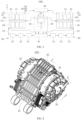
- the electric drive assembly 1001 provided by the present disclosure includes: a motor 20; a speed shifting mechanism 30 connected to the motor 20; and a cooling system 40 configured to supply lubricating oil to the motor 20 and the speed shifting mechanism 30 in sequence.
- the motor 20 is the power source component of the electric drive assembly 1001, and the motor 20 refers to an electromagnetic device for converting or transmitting electric energy according to the law of electromagnetic induction.
- the speed shifting mechanism 30 is a mechanism for changing the speed and torque from a motor 20, which enables fixed or stepped changes in the speed shifting mechanism ratio of the output shaft and the input shaft.
- the speed shifting mechanism 30 may be a gear mechanism, a belt drive mechanism, or the like.
- the speed shifting mechanism 30 is connected to the motor 20 and is driven by the motor 20 to output torque through the speed shifting mechanism 30.
- the cooling system 40 refers to a structural system for supplying lubricating oil to cool the motor 20 and lubricating the speed shifting mechanism 30.
- the cooling system 40 sequentially supplies lubricating oil to the motor 20 and the speed shifting mechanism 30, in other word, the cooling system 40 supplies the lubricating oil to the motor 20, so that the motor 20 is cooled. Then, the lubricating oil enters the speed shifting mechanism 30 after flowing out of the motor 20, so that the speed shifting mechanism 30 is lubricated.
- the motor 20 and the speed shifting mechanism 30 are sequentially supplied with lubricating oil to reduce the loss of the cooling capacity of lubricating oil in the speed shifting mechanism 30, so as to improve the cooling efficiency and the utilization rate of the cooling capacity, and reduce the loss.
- the cooling system 40 supplies oil to the motor 20 and cools the motor 20
- the motor 20 has an oil inlet and an oil outlet, so that the oil enters and flows out of the motor 20.
- the electric drive assembly 1001 has a height direction, a width direction, and a length direction.
- the Z-axis direction is the height direction
- the Y-axis direction is the width direction
- the X-axis direction is the length direction.
- the Z-axis direction, the X-axis direction, and the Y-axis direction are perpendicular to each other.
- the Z-axis direction is generally vertical
- the X-axis and Y-axis are two directions in the horizontal plane.
- a certain error or tilt may be allowed in specific use.
- the axial direction of the motor 20 is along the Y-axis.
- the motor 20 includes a first heat generating portion and a second heat generating portion.
- the cooling system 40 supplies lubricating oil to the first heat generating portion and the second heat generating portion in turn.
- the first heat generating portion refers to a part of a heating component in the motor 20, such as a stator 22, a rotor 21, or a control element.
- the first heat generating portion refers to another portion of the heating components in the motor 20, such as the stator 22, the rotor 21, or a control element.
- the second heat generating portion may be at least part of the rotor 21.
- the second heat generating portion may be at least part of the rotor 21.
- the first heat generating portion includes a stator oil passage 23 for cooling the stator 22 of the motor 20.
- the cooling system 40 is connected to the stator oil passage 23.
- the stator oil passage 23 is an oil passage that can receive lubricating oil in the motor 20 and cool the stator 22. Since lubricating oil flows through the stator oil passage 23 to cool the stator 22, the stator oil passage 23 has an oil inlet end and an oil outlet end.
- the oil inlet end of the stator oil passage 23 refers to an end through which lubricating oil enters the stator oil passage 23, and the oil outlet end of the stator oil passage 23 refers to an end through which lubricating oil flows out of the stator oil passage 23.
- the stator oil passage 23 is connected to the cooling system 40 so that the cooling system 40 supplies lubricating oil to the stator oil passage 23 to cool the stator 22.
- the stator oil passage 23 is provided in the motor 20 to cool the stator 22 of the motor 20 so that the stator 22 can be smoothly operated.
- the second heat generating portion includes a rotor oil passage 24 for cooling the rotor 21 of the motor 20.
- the cooling system 40 is connected to the rotor oil passage 24.
- the rotor oil passage 24 is an oil passage that can receive lubricating oil in the motor 20 and cool the rotor 21. Since lubricating oil flows through the rotor oil passage 24 to cool the rotor 21, the rotor oil passage 24 has an oil inlet end and an oil outlet end.
- the oil inlet end of the rotor oil passage 24 refers to an end through which lubricating oil enters the rotor oil passage 24, and the oil outlet end of the rotor oil passage 24 refers to an end through which lubricating oil flows out of the rotor oil passage 24.
- the rotor oil passage 24 is connected to a cooling system 40 so that the cooling system 40 supplies lubricating oil to the rotor oil passage 24 to cool the rotor 21.
- the rotor oil passage 24 is provided in the motor 20 to cool the rotor 21 of the motor 20 so that the rotor 21 can smoothly operate.
- the electric drive assembly 1001 further includes a flow guiding structure 70 configured to guide a part of lubricating oil flowing out of the stator oil passage 23 to the rotor oil passage 24.
- the flow guiding structure 70 refers to a structure that can guide at least part of lubricating oil flowing out of the stator oil passage 23 to the rotor oil passage 24.
- the form of the flow guiding structure 70 may be various, including but not limited to: a pipe through which lubricating oil is guided to the rotor oil passage 24.
- the heat generated by the stator 22 is usually large.
- the flow guiding structure 70 to guide a part of lubricating oil flowing out of the stator oil passage 23 to the rotor oil passage 24, it can not only cool the stator oil passage 23 firstly, so as to make full use of the cooling capacity in lubricating oil and improve the utilization rate of the cooling capacity but also realize the series connection between the stator oil passage 23 and the rotor oil passage 24, so as to improve the utilization rate of the cooling capacity of lubricating oil.
- the amount of lubricating oil entering the rotor oil passage 24 can be controlled, so as to reduce oil agitation loss when the rotor 21 rotates and improve the working efficiency of the motor 20.
- the motor 20 includes a rotor shaft 211.
- the rotor oil passage 24 has a first shaft hole 241 disposed in the rotor shaft 211.
- the first shaft hole 241 extends along an axial direction of the rotor shaft 211.
- the flow guiding structure 70 is connected to the first shaft hole 241.
- the rotor shaft 211 refers to a shaft structure provided on the rotor 21.
- power is output to the outside through the rotor shaft 211.
- the first shaft hole 241 refers to a hole structure formed at the rotor shaft 211.
- the first shaft hole 241 extends in the axial direction of the rotor shaft 211.
- lubricating oil flows through the first shaft hole 241, the rotor shaft 211 and in turn the rotor 21 can be cooled.
- lubricating oil can be delivered to the rotor shaft 211 to cool the rotor 21, thereby providing a good temperature environment for rotor 21 operation.
- the first shaft hole 241 is formed at the rotor oil passage 24, so that the rotor oil passage 24 is easily manufactured. agitation of the lubricant by the rotor 21 can be reduced and agitation loss can be reduced.
- a spray structure may also be provided in a recess in the housing of the motor 20 where the rotor 21 portion is mounted to spray lubricant onto the rotor 21 to cool the rotor 21.
- the temperature of the rotor 21 and the oil agitation loss are well controlled by controlling the amount of the spray oil.
- a housing 25 of the motor 20 refers to a housing structure that accommodate internal components of the motor 20, such as the stator 22 and the rotor 21.
- the speed shifting mechanism 30 includes an input shaft 31.
- the input shaft 31 is coaxially connected to the rotor shaft 211.
- the input shaft 31 is axially provided with a second shaft hole 311.
- the flow guiding structure 70 is connected to the first shaft hole 241 through the second shaft hole 311.
- the input shaft 31 refers to a shaft structure on the speed shifting mechanism 30, and is configured to be connected to the rotor shaft 211 of the motor 20, and drive other components of the speed shifting mechanism 30 to rotate through the input shaft 31.
- the input shaft 31 is coaxially connected to the rotor shaft 211, so that the rotor shaft 211 drives the input shaft 31 to rotate.
- the second shaft hole 311 refers to a hole structure formed at the input shaft 31.
- the second shaft hole 311 may be connected to the first shaft hole 241 in the rotor shaft 211.
- the flow guiding structure 70 is connected to the first shaft hole 241 through the second shaft hole 311, in other words, the flow guiding structure 70 is connected to the second shaft hole 311 and in turn connected to the first shaft hole 241 through the second shaft hole 311.
- the input shaft 31 is connected to the rotor shaft 211, so that the rotor shaft 211 drives the input shaft 31 to rotate.
- the second shaft hole 311 is formed at the input shaft 31, so that the second shaft hole 311 is connected to the first shaft hole 241.
- the flow guiding structure 70 can be connected to the first shaft hole 241 as long as the flow guiding structure 70 is connected to the second shaft hole 311, so as to guide lubricating oil to the first shaft hole 241, thereby cooling the rotor 21.
- the flow guiding structure 70 may also be in direct connection with the first shaft hole 241 of the rotor shaft 211.
- an end of the input shaft 31 away from the rotor shaft 211 is provided with a first bearing 351.
- the electric drive assembly 1001 further includes a casing 10.
- the casing 10 has an accommodating cavity 11 for accommodating the speed shifting mechanism 30 and a first bearing chamber 121 for mounting the first bearing 351 in cooperation therewith.
- the first bearing chamber 121 is in connection with the accommodating cavity 11.
- the cooling system 40 is in connection with the first bearing chamber 121.
- the flow guiding structure 70 guides part of lubricating oil in the first bearing chamber 121 to the second shaft hole 311.
- the bearing is a structure for supporting the rotation of a shaft, and generally includes an outer ring, an inner ring, and a ball arranged between the outer ring and the inner ring.
- the inner ring is typically mounted at the shaft and the outer ring is typically mounted in the bearing housing, so that the shaft is rotatably supported.
- the first bearing 351 is a bearing supporting the input shaft 31. An end of the input shaft 31 away from the rotor shaft 211 is provided with a first bearing 351.
- the casing 10 refers to the outer casing of the electric drive assembly 1001 to accommodate and support the internal components of drive assembly 1001.
- the accommodating cavity 11 refers to a chamber provided in the casing 10 configured to accommodate and mount the speed shifting mechanism 30, that is, the speed shifting mechanism 30 is mounted in the accommodating cavity 11.
- the bearing chamber refers to a chamber that accommodates and mounts a bearing.
- the first bearing chamber 121 refers to a chamber formed in the casing 10 and configured to fittingly mount the first bearing 351.
- the first bearing chamber 121 is connected to the accommodating cavity 11, so that the first bearing 351 can be moved to the first bearing chamber 121 from the accommodating cavity 11 and mounted in the first bearing chamber 121, facilitating assembly. In addition, it is also convenient for lubricating oil lubricating the first bearing 351 in the first bearing chamber 121 to flow to the accommodating cavity 11.
- the cooling system 40 is connected to the first bearing chamber 121 to supply lubricating oil into the first bearing chamber 121.
- the flow guiding structure 70 guides a part of lubricating oil in the first bearing chamber 121 to the second shaft hole 311, so as to supply lubricating oil to the second shaft hole 311 and in turn to supply lubricating oil into the first shaft hole 241, so that the rotor 21 is cooled.
- the first bearing chamber 121 has a first oil inlet 1211 in connection with the cooling system 40.
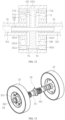
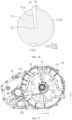
- the flow guiding structure 70 includes a flow guiding disc 71 mounted in the first bearing chamber 121, so that the flow guiding disc 71 is configured to receive lubricating oil from the first oil inlet 1211 and guide the lubricating oil to the second shaft hole 311 and the first bearing 351.
- the first oil inlet 1211 refers to a hole or an opening structure provided in the first bearing chamber 121.
- the first oil inlet 1211 is provided in the first bearing chamber 121 so that the first bearing chamber 121 is connected to the cooling system 40, thereby facilitating the supply of lubricating oil into the first bearing chamber 121 through the cooling system 40.
- the flow guiding disc 71 refers to a structural member configured to guide the flow direction of lubricating oil.
- the flow guiding disc 71 may be provided in a disc-shaped structure so as to facilitate manufacturing.
- the flow guiding disc 71 may be provided in a polygonal shape, an elliptical shape, or the like.
- the flow guiding disc 71 is mounted in the first bearing chamber 121 to mount and support the flow guiding disc 71 and to facilitate the flow of the lubricant in the first bearing chamber 121 by the flow guiding disc 71.
- the first oil inlet 1211 is formed at the first bearing chamber 121, so that the first bearing chamber 121 is connected to the cooling system 40, it is convenient for the cooling system 40 to supply lubricating oil to the first bearing chamber 121.
- the lubricating oil 1211 entering the first oil inlet can be guided to the second shaft hole 311 and the first bearing 351, so that oil is supplied to the first shaft hole 241 through the second shaft hole 311 to cool the rotor 21, and oil is supplied to the first bearing 351 to lubricate the first bearing 351.
- the structure is simple, convenient for processing and manufacture, and can reduce the occupied space.
- the flow guiding disc 71 is provided with a central tube 72 extending in an axial direction of the flow guiding disc.
- the central tube 72 is connected to the second axial hole 311.
- the flow guiding disc 71 has a first flow guiding channel 711.
- the first flow guiding channel 711 has an end connected to the central tube 72 and another end extending to a peripheral side surface of the flow guiding disc 71 and located adjacent to the first oil inlet 1211.
- the central tube 72 refers to a tube structure provided on the flow guiding disc 71.
- the central tube 72 is disposed along the axial extension of the flow guiding disc 71.
- the central tube 72 is connected to the second shaft hole 311 into which the central tube 72 can be inserted to connect the central tube 72 with the second shaft hole 311 and allow relative rotation of the central tube 72 and the input shaft 31.
- the central tube 72 may also be connected to the input shaft 31 such that the central tube 72 is connected to the second shaft hole 311.
- the first flow guiding channel 711 refers to a channel structure formed at the flow guiding disc 71 and through which lubricating oil can flow.
- the first flow guiding channel 711 has an end connected to the central tube 72 and another end extending to the peripheral side surface of the flow guiding disc 71, in other word, the first flow guiding channel 711 is connected to the central tube 72 and the peripheral side surface of the flow guiding disc 71, so that lubricating oil on the peripheral side surface of the flow guiding disc 71 can enter the central tube 72 through the first flow guiding channel 711.
- the other end of the first flow guiding channel 711 is located adjacent to the first oil inlet 1211, in other word, one end of the first flow guiding channel 711 on the peripheral side surface of the flow guiding disc 71 is adjacent to the first oil inlet 1211, that is, the other end of the first flow guiding channel 711 is located adjacent to the first oil inlet 1211, so that the lubricating oil entering the first oil inlet 1211 flows to the first flow guiding channel 711 and then is guided to the central tube 72.
- the flow guiding disc 71 By providing a central tube 72 on the flow guiding disc 71, so that the flow guiding disc 71 is connected to the second shaft hole 311 and then to the first shaft hole 241.
- a first flow guiding channel 711 in the flow guiding disc 71 so that the peripheral side surface of the flow guiding disc 71 is connected to the central tube 72.
- One end of the first flow guiding channel 711 away from the central tube 72 is located adjacent to the first oil inlet 1211, so that the lubricating oil entering the first oil inlet 1211 flows to the first flow guiding channel 711, then flows to the central tube 72, then is guided to the second shaft hole 311 through the central tube 72, and then flows to the first shaft hole 241 so as to cool the rotor 21.
- the structure is simple, convenient to manufacture, and easy to assemble.
- the first flow guiding channel 711 extends radially of the flow guiding disc 71 to facilitate manufacturing. It will be appreciated that the first flow guiding channel 711 may also be curved so long as it can guide the incoming lubrication oil to the central tube 72.
- a side surface of the flow guiding disc 71 close to the first bearing 351 is provided with a collar 73 protruding in an axial direction of the flow guiding disc 71.
- the collar 73 is fitted with an outer ring of the first bearing 351 and has a recess 730 therein.
- the flow guiding disc 71 has a second flow guiding channel 712.
- the second flow guiding channel 712 has an end extending to the recess 730 and another end extending to the peripheral side surface of the flow guiding disc 71.
- the collar 73 refers to an annular boss structure provided on the side surface of the flow guiding disc 71.
- the interior space of the collar 73 may thus form a recess 730.
- the collar 73 being fitted with an outer ring of the first bearing 351 meant that when the flow guiding disc 71 and the first bearing 351 are mounted in the first bearing chamber 121, the collar 73 engages with the outer ring of the first bearing 351, so that lubricating oil entering the first bearing chamber 121 is blocked outside the first bearing 351 through the collar 73.
- the second flow guiding channel 712 refers to a passage structure formed at the flow guiding disc 71 and through which lubricating oil can flow.
- the second flow guiding channel 712 has an end extending to the recess 730 and another end extending to the peripheral side surface of the flow guiding disc 71, in other word, the second flow guiding channel 712 connects the recess 730 with the peripheral side surface of the flow guiding disc 71, so that lubricating oil on the peripheral side surface of the flow guiding disc 71 can enter the recess 730 through the second flow guiding channel 712.
- the first bearing 351 can be positioned, lubricating oil entering the first bearing chamber 121 through the first oil inlet 1211 can flow along the peripheral side surface of the flow guiding disc 71 so as to facilitate lubricating oil entering the first flow guiding channel 711.
- lubricating oil flowing along the peripheral side surface of the flow guiding disc 71 can enter the recess 730 through the second flow guiding channel 712, and then enter the first bearing 351 from the recess 730, so as to lubricate the first bearing 351.
- the structure is simple, convenient to manufacture, and easy to assembly.
- the first bearing 351 generally includes, as an example of a rolling bearing, an outer ring 3511, an inner ring 3512, and a rolling element 3513.
- the rolling element 3513 is located between the outer ring 3511 and the inner ring 3512.
- the outer ring 3511 is fixedly supported in the first bearing chamber 121, and the inner ring 3512 is fixedly connected to a rotating shaft, such as the input shaft 31.
- lubricating oil needs to be sent to between the outer ring 3511 and the inner ring 3512, that is, to the rolling element 3513.
- the collar 73 is adjoined to the outer ring 3511 to position the first bearing 351.
- lubricating oil introduced into the first bearing chamber 121 from the first oil inlet 1211 is introduced into the central tube 72 from the first flow guiding channel 711 and into the second shaft hole 311 of the input shaft 31 to supply lubricating oil to the second shaft hole 311.
- Another portion of lubricating oil introduced into the first bearing chamber 121 from the first oil inlet 1211 enters the recess 730 from the second flow guiding channel 712, and in turn enters between the outer ring 3511 and the inner ring 3512 of the first bearing 351 from the recess 730 so as to lubricate the rolling element 3513 of the first bearing 351.
- the other end of the second flow guiding channel 712 is located adjacent to the first oil inlet 1211.
- the other end of the second flow guiding channel 712 is located on the peripheral side surface of the flow guiding disc 71 and is provided adjacent to the first oil inlet 1211, so that the lubricating oil entering the first oil inlet 1211 flows to the flow guiding disc 71 and is then guided to the recess 730 through the flow guiding disc 71.
- the flow guiding disc 71 may be fabricated separately and mounted in the first bearing housing 121 to facilitate fabrication and assembly.
- the flow guiding disc 71 may also be integrally formed with the casing 10, that is, a structure in which the flow guiding disc 71 is formed directly during processing of the casing 10.
- the other end of the first flow guiding channel 711 is adjoined to the other end of the second flow guiding channel 712.
- the other end of the first flow guiding channel 711 is an end of the first flow guiding channel 711 extending to the peripheral side surface of the flow guiding disc 71, and is also used as an inlet end of the first flow guiding channel 711.
- the other end of the second flow guiding channel 712 is an end of the second flow guiding channel 712 extending to the peripheral side surface of the flow guiding disc 71, and is also used as an inlet end of the second flow guiding channel 712.
- the other end of the first flow guiding channel 711 is adjoined to the other end of the second flow guiding channel 712, which not only facilitates processing and manufacture, but also facilitates the lubricating oil entering the first oil inlet 1211 to flow to the first and second flow guiding channels 711 and 712.
- a partition plate 74 is disposed between the other end of the first flow guiding channel 711 and the other end of the second flow guiding channel 712.
- the partition plate 74 refers to a plate-shaped structure provided on the flow guiding disc 71.
- the partition plate 74 is located between the other end of the first flow guiding channel 711 and the other end of the second flow guiding channel 712, that is, the partition plate 74 is located between the inlet end of the first flow guiding channel 711 and the inlet end of the second flow guiding channel 712.
- the lubricating oil entering the first oil inlet 1211 flows to the first flow guiding channel 711 and the second flow guiding channel 712, respectively, so as to control the amount of lubricating oil entering the first flow guiding channel 711 and the second flow guiding channel 712, and in turn control the amount of lubricating oil entering the rotor shaft 211.
- the partition plate 74 may be disposed on the flow guiding disc 71 in a variety of modes.
- the partition plate 74 may be welded to the flow guiding disc 71 or integrally formed with the flow guiding disc 71.
- both sides of the partition plate 74 are provided with baffles 75 to cooperate with the partition plate 74, thereby guiding lubricating oil into the first and second flow guiding channels 711 and 712, respectively.
- the second flow guiding channel 712 has a notch 7121 formed at the collar 73, and the notch 7121 is in connection with the recess 730.
- the notch 7121 refers to a mouth-shaped structure formed at the collar 73.
- the notch 7121 connects the recess 730 with the peripheral side surface of the flow guiding disc 71 so that lubricating oil on the peripheral side surface of the flow guiding disc 71 can enter the recess 730 from the notch 7121.
- the second flow guiding channel 712 can be formed.
- the structure is simple, and convenient to manufacture.
- the notch 7121 may be located in a lower part of the collar 73 in the height direction Z such that there is lubricating oil with a certain height on the outside of the flow guiding disc 71 in the first bearing chamber 121.
- the lubricating oil enters into the recess 730 from the notch 7121, so that the first bearing 351 is lubricated.
- connection flow passage 7122 may be provided at a peripheral side surface of the flow guiding disc 71 or inside the flow guiding disc 71, so that the flow guiding disc 71 is connected to the notch 7121 and guides lubricating oil to the notch 7121.
- the second flow guiding channel 712 may be formed at the flow guiding disc 71.
- One end of the second flow guiding channel 712 is located at the side of the flow guiding disc 71, that is, at the bottom of the depth direction of the recess 730, to guide lubricating oil directly into the recess 730.
- the first flow guiding channel 711 and the second flow guiding channel 712 may also share a segment.
- a hole structure may be formed at the side of the first flow guiding channel 711, so that the first flow guiding channel 711 is connected to the recess 730, and lubricating oil in the first flow guiding channel 711 may flow into the central tube 72 and the recess 730, respectively.
- an oil return channel 251 is provided at the housing 25 of the motor 20.
- the oil return channel 251 is in connection with an end of the first shaft hole 241 away from the speed shifting mechanism 30.
- the electric drive assembly 1001 further includes an oil sump 81, and the oil return channel 251 is in connection with the oil sump 81.
- the oil return channel 251 refers to a passage for guiding lubricating oil to return to the oil sump 81 and may be a pipe, a channel, or the like.
- the oil sump 81 refers to a space for accommodating lubricating oil.
- the oil sump 81 may be provided separately and mounted on the casing 10 of the electric drive assembly 1001.
- the bottom of the casing 10 can be used as an oil sump 81.
- the bottom of the casing 10 in the height direction of the accommodating cavity 11 for mounting the speed shifting mechanism 30 is used as the oil sump 81, so as to improve the integration and also facilitate the backflow of lubricating oil.
- the oil return channel 251 is disposed at the housing 25 of the motor 20 to connect the first shaft hole 241 with the oil sump 81, which facilitates lubricating oil entering the first shaft hole 241 to flow to the oil sump 81, and facilitates the recovery of lubricating oil.
- the oil sump 81 is formed at the bottom of the accommodating cavity 11 of the casing 10 in which the speed shifting mechanism 30 is mounted, that is, the oil sump 81 is formed at the bottom of the accommodating cavity 11 of the casing 10, so that the oil sump 81 does not need to be separately provided, simplifying the structure.
- the inner space of the accommodating cavity 11 of the casing 10 can be fully utilized.
- the backflow of lubricating oil on the speed shifting mechanism 30 can be facilitated.
- the integration degree can be improved, and the volume of the electric drive assembly 1001 can be reduced.
- the housing 25 of the motor 20 has an oil return hole 252 that connects the oil return channel 251 with the oil sump 81.
- the oil return hole 252 refers to an open hole structure provided on the housing 25 of the motor 20.
- the oil return hole 252 is formed at the housing 25 of the motor 20 to connect the oil return channel 251 with the oil sump 81 which facilitates lubricating oil entering the first shaft hole 241 to flow to the oil sump 81.
- the oil return hole 252 may be disposed outside the housing 25 of the motor 20, and the outer side of the housing 25 of the motor 20 may need to be provided with an end cap 26 to cover the outer side of the housing 25 of the motor 20 for protection.
- the flow guiding structure 70 is also configured to guide a part of lubricating oil flowing out of the stator oil passage 23 to the speed shifting mechanism 30.
- the flow guiding structure 70 guides a part of lubricating oil flowing out of the stator oil passage 23 to the speed shifting mechanism 30, so that the flow guiding structure 70 guides lubricating oil flowing out of the stator oil passage 23 to the speed shifting mechanism 30 and the rotor oil passage 24, so as to cool the rotor 21 and lubricate the speed shifting mechanism 30.
- the flow guiding structure 70 may take a variety of configurations including, but not limited to: a pipe member configured to guide lubricating oil flowing out of the stator oil passage 23 to the speed shifting mechanism 30 and the rotor oil passage 24.
- the speed shifting mechanism 30 includes an input shaft 31 that is axially perforated with a second shaft hole 311.
- the flow guiding structure 70 is in connection with the second shaft hole 311.
- the flow guiding structure 70 guides the lubricating oil to the second shaft hole 311, so that the input shaft 31 is cooled and the input shaft 31 is also lubricated.
- the cooling system 40 includes a flow diverting mechanism 60 connected to the motor 20 and configured to deliver lubricating oil flowing out of the motor 20 to the speed shifting mechanism 30.
- the flow diverting mechanism 60 can guide at least part of lubricating oil flowing out of motor 20 to speed shifting mechanism 30.
- Flow diverting mechanism 60 may take a variety of configurations, including but not limited to: a pipe through which lubricating oil is guided to the speed shifting mechanism 30.
- a nozzle structure through which lubricating oil is injected into the speed shifting mechanism 30.
- the flow diverting mechanism 60 may be connected to an oil outlet end of the stator oil passage 23, so that lubricating oil flowing out of the stator oil passage 23 may enter the flow diverting mechanism 60 which guides lubricating oil to the speed shifting mechanism 30.
- the flow diverting mechanism 60 may be connected to an oil outlet end of the rotor oil passage 24, so that lubricating oil flowing out of the rotor oil passage 24 may enter the flow diverting mechanism 60 which guides lubricating oil to the speed shifting mechanism 30.
- the flow diverting mechanism 60 has an end connected to an oil outlet end of the stator oil passage 23 of the motor 20 and another end connected to each of the oil inlet end of the rotor oil passage 24 of the motor 20 and the speed shifting mechanism 30.
- the flow diverting mechanism 60 has an end connected to the oil outlet end of the stator oil passage 23 and another end connected to the oil inlet end of the rotor oil passage 24, so that lubricating oil in the stator oil passage 23 cools the rotor 21.
- the other end of the flow diverting mechanism 60 is connected with the speed shifting mechanism 30 so as to lubricate the speed shifting mechanism 30 so as to improve the utilization efficiency of lubricating oil.
- the flow diverting mechanism 60 includes a flow collecting tube 61 connected to the oil outlet end of the motor 20.
- the flow collecting tube 61 refers to a tube structure connected to an oil outlet end of the motor 20 to receive lubricating oil discharged from the motor 20.
- the flow collecting tube 61 is provided so as to receive lubricating oil discharged from the motor 20 and to guide lubricating oil discharged from the motor 20 to the speed shifting mechanism 30.
- the flow collecting tube 61 is connected to the oil outlet end of the stator oil passage 23.
- the flow collecting tube 61 is connected to the oil outlet end of the rotor oil passage 24.
- the flow diverting mechanism 60 further includes a flow diverting structure 62 configured to guide lubricating oil in the flow collecting tube 61 to the speed shifting mechanism 30.
- the flow diverting structure 62 is connected to the flow collecting tube 61.
- the draining structure 62 refers to structures used to guide the flow of lubricating oil, including, but not limited to, pipe structures, trough structures, nozzles, and the like.
- the flow diverting structure 62 is connected to the flow collecting tube 61 so that lubricating oil in the flow collecting tube 61 can flow to the flow diverting structure 62 so that the flow diverting structure 62 serves to guide lubricating oil in the flow collecting tube 61 to the speed shifting mechanism 30, thereby lubricating the speed shifting mechanism 30.
- the speed shifting mechanism 30 includes an input shaft 31 connected to the motor 20; an output shaft 32; and a transmission component 34 in a driving connection with the input shaft 31 and the output shaft 32.
- the flow diverting structure 62 includes a flow diverting tube 622 connected to the flow collecting tube 61 and configured to guide lubricating oil to the transmission component 34.
- the input shaft 31 refers to a shaft structure on the speed shifting mechanism 30, and is configured to be connected to the rotor shaft 211 of the motor 20, and drive other components of the speed shifting mechanism 30 to rotate through the input shaft 31.
- the input shaft 31 is connected to the motor 20 so that the motor 20 drives the input shaft 31 to rotate.
- the motor 20 includes a rotor shaft 211
- the input shaft 31 is coupled to the rotor shaft 211 of the motor 20.
- the output shaft 32 refers to a shaft structure of the speed shifting mechanism 30 configured to be connected to an external device for power output.
- the transmission component 34 is a component for transmitting power.
- the transmission component 34 typically employs a gear drive, also known as a planetary gear drive, as well as a belt drive.
- the transmission component 34 drivingly connects the input shaft 31 and the output shaft 32, so that when the input shaft 31 rotates, the output shaft 32 is driven to rotate through the transmission component 34 to achieve power output.
- the flow diverting tube 622 is a piping structure that guides the flow of lubricating oil.
- the flow diverting tube 622 is connected to flow collecting tube 61 to guide lubricating oil from flow collecting tube 61 to the transmission component 34 to lubricate transmission component 34.
- the structure is simple and ease to assembly.
- the speed shifting mechanism 30 includes an input shaft 31 connected to the motor 20; an output shaft 32; a transmission component 34 drivingly connecting the input shaft 31 and the output shaft 32.
- the flow diverting mechanism 60 includes a flow collecting tube 61 connected to the motor 20; a flow diverting tube 622 connected to the flow collecting tube 61 and configured to guide lubricating oil to the transmission component 34.
- the flow collecting tube 61 is disposed to be connected to the motor 20, which facilitates lubricating oil flowing out of the motor 20 to flow to the flow collecting tube 61.
- the transmission component 34 can be lubricated.
- the structure is simple and easy to assemble.
- the flow diverting mechanism 60 further includes a shunt plate 621 connected to the flow collecting tube 61.
- the flow diverting tube 622 is connected to the shunt plate 621.
- the shunt plate 621 has a flow diverting groove 6211 that connects the flow collecting tube 61 with the flow diverting tube 622.
- the shunt plate 621 refers to a plate member structure that shunts lubricating oil.
- the flow diverting groove 6211 is a groove structure provided on the shunt plate 621 and guides the flow of lubricating oil.
- the shunt plate 621 is connected to the flow collecting tube 61.
- the flow diverting tube 622 is connected to the shunt plate 621.
- the flow diverting groove 6211 connects the flow collecting tube 61 with the flow diverting tube 622, so that lubricating oil in the flow collecting tube 61 can flow to the flow diverting tube 622 through the flow diverting groove 6211, and then is guided to the speed shifting mechanism 30, thereby lubricating the speed shifting mechanism 30.
- the shunt plate 621 is provided and the flow diverting groove 6211 is formed at the shunt plate 621, so that lubricating oil in the flow collecting tube 61 is guided to the flow diverting tube 622.
- the structure is simple, and easy to process, manufacture, install and fix. The integration degree can be improved and the occupied space can be reduced.
- the flow diverting structure 62 which may also be the flow diverting mechanism 60, includes a shunt plate 621. Because the flow diverting mechanism 60 includes the flow diverting structure 62, when the flow diverting structure 62 includes the shunt plate 621, the flow diverting mechanism 60 also includes the shunt plate 621.
- the transmission component 34 includes a first gear 341 fixedly disposed at the input shaft 31, a second gear 342 fixedly disposed at the output shaft 32, and at least one intermediate gear 343 in transmission mesh with each of the first gear 341 and the second gear 342.
- the speed shifting mechanism 30 further includes an intermediate shaft 33 configured to support the at least one intermediate gear 343.
- the flow diverting tube 622 includes a first flow diverting tube 6221 extending to a position below which the first gear 341 meshes with the at least one intermediate gear 343; and a second flow diverting tube 6222 extending to a position below which the second gear 342 meshes with the at least one intermediate gear 343.
- the first gear 341 refers to a gear structure mounted on the input shaft 31, and when the input shaft 31 rotates, the first gear 341 can be driven to rotate.
- the second gear 342 refers to a gear structure mounted on the output shaft 32, and can rotate the output shaft 32 when the second gear 342 rotates.
- the intermediate gear 343 is a gear provided between the first gear 341 and the second gear 342 to achieve gears in drive connection. When the first gear 341 rotates, the intermediate gear 343 rotates to drive the second gear 342 to rotate.
- the intermediate gear 343 may be one, two, three, etc.
- the intermediate shaft 33 refers to a shaft structure for supporting the intermediate gear 343 so that the intermediate gear 343 can rotate smoothly.
- the first flow diverting tube 6221 refers to a pipe structure that guides the flow of lubricating oil.
- the first flow diverting tube 6221 extends to a position below which the first gear 341 meshes with the corresponding intermediate gear 343, so that lubricating oil guided out by the first flow diverting tube 6221 can reach the region where the first gear 341 meshes with the corresponding intermediate gear 343, so as to lubricate the region where the first gear 341 meshes with the intermediate gear 343, reducing the wear and tear.
- the second flow diverting tube 6222 refers to a pipe structure that guides the flow of lubricating oil.
- the second flow diverting tube 6222 extends to a position below which the second gear 342 meshes with the corresponding intermediate gear 343, so that lubricating oil guided out by the second flow diverting tube 6222 can reach the region where the second gear 342 meshes with the corresponding intermediate gear 343, so as to lubricate the region where the second gear 342 meshes with the intermediate gear 343, reducing the wear and tear.
- the speed shifting mechanism 30 further includes a plurality of support bearings 35 that respectively support the input shaft 31, the output shaft 32, and the intermediate shaft 33.
- the electric drive assembly 1001 further includes a casing 10.
- the casing 10 is provided with a bearing chamber 12 configured to cooperatively accommodate each support bearing 35.
- the flow diverting mechanism 60 further includes a shunt tube 623 configured to guide lubricating oil to each of the bearing chambers 12.
- the shunt tube 623 is connected to the flow collecting tube 61.
- the support bearing 35 refers to a bearing structure for supporting a shaft member.
- Support bearings 35 are provided on the input shaft 31, the output shaft 32, and the intermediate shaft 33, respectively, not only support the input shaft 31, the output shaft 32, and the intermediate shaft 33, but also facilitate flexible and smooth rotation of the input shaft 31, the output shaft 32, and the intermediate shaft 33.
- the shunt tube 623 refers to a pipe structure that guides the flow of lubricating oil.
- the shunt tube 623 is connected to the flow collecting tube 61 so as to guide lubricating oil in the flow collecting tube 61 to each of the bearing chambers 12 to lubricate the support bearings 35 of each of the bearing chambers 12.
- the support bearings 35 of the speed shifting mechanism 30 is lubricated, to ensure flexible and smooth operation of the speed shifting mechanism 30 and reduce wear and tear.
- the flow diverting structure 62 which may also be the flow diverting mechanism 60, includes a shunt tube 623. Because the flow diverting mechanism 60 includes the flow diverting structure 62, when the flow diverting structure 62 includes the shunt tube 623, the flow diverting mechanism 60 also includes the shunt tube 623.
- the flow diverting mechanism 60 further includes: a shunt plate 621 connected to the flow collecting tube 61.
- the shunt tube 623 is connected to the shunt plate 621.
- the shunt plate 621 is provided with a shunt groove 6212.
- the shunt groove 6212 connects the flow collecting tube 61 with the shunt tube 623.
- the shunt plate 621 refers to a plate member structure that shunts lubricating oil.
- the shunt groove 6212 is a groove structure formed at the shunt plate 621 and guides the flow of lubricating oil.
- the shunt plate 621 is connected to the flow collecting tube 61.
- the shunt tube 623 is connected to the shunt plate 621.
- the shunt groove 6212 connects the flow collecting tube 61 with the shunt tube 623, so that lubricating oil in the flow collecting tube 61 can flow to the shunt tube 623 through the shunt groove 6212, and then is guided to the speed shifting mechanism 30, thereby lubricating the speed shifting mechanism 30.
- the shunt plate 621 By providing the shunt plate 621 and providing the shunt groove 6212 on the shunt plate 621, it is convenient to guide lubricating oil in the flow collecting tube 61 to the shunt tube 623.
- the structure is simple, and easy to process, manufacture, install and fix. The integration degree can be improved and the occupied space can be reduced.
- the shunt plate 621 and the shunt tube 623 may be integrally formed structures to facilitate fabrication.
- the shunt plate 621 and the shunt tube 623 may be made separately and fixedly connected.
- the shunt plate 621 and the flow diverting tube 622 may be integrally formed structures to facilitate fabrication.
- the shunt plate 621 and the flow diverting tube 622 may be made separately and fixedly connected.
- the shunt plate 621 and the flow collecting tube 61 may be integrally formed to facilitate fabrication.
- the shunt plate 621 and the flow collecting tube 61 may be formed separately and fixedly connected.
- the side of the flow collecting tube 61 has a first opening 611 to connect the flow diverting groove 6211.
- the side of the flow collecting tube 61 has a second opening 612 to connect the shunt groove 6212.
- the bottom of the first opening 611 is convexly provided with a first retaining wall 613, and the bottom of the second opening 612 is convexly provided with a second retaining wall 614, so that lubricating oil can flow in the flow collecting tube 61.
- the lubricating oil in the flow collecting tube 61 overflows out of the first opening 611 and the second opening 612 to enter the flow diverting groove 6211 and the shunt groove 6212, so as to well distribute lubricating oil into the flow diverting groove 6211 and the shunt groove 6212.
- the support bearing 35 includes a first bearing 351 disposed at the input shaft 31, a second bearing 352 disposed at the output shaft 32, and a third bearing 353 disposed at the intermediate shaft 33.
- the bearing chamber 12 includes a first bearing chamber 121 configured for mounting of the first bearing 351, a second bearing chamber 122 accommodating the second bearing 352, and a third bearing chamber 123 accommodating the third bearing 353.
- the shunt tube 623 includes a first shunt tube 6231 connecting the first bearing chamber 121 with the third bearing chamber 123; and a second shunt tube 6232 connected to the second bearing chamber 122.
- the first bearing 351 is a bearing for rotating the input shaft 31.
- the first bearings 351 may be respectively provided at both ends of the input shaft 31 to smoothly support the input shaft 31 so that the input shaft 31 can rotate flexibly.
- the first bearing 351 is mounted in the first bearing chamber 121.
- the second bearing 352 is a bearing for rotating the output shaft 32.
- the second bearings 352 may be respectively provided at both ends of the output shaft 32 to smoothly support the output shaft 32 so that the output shaft 32 can rotate flexibly.
- the second bearing 352 is mounted in the second bearing chamber 122.
- the third bearing 353 is a bearing for rotating the intermediate shaft 33.
- the third bearings 353 may be respectively provided at both ends of the intermediate shaft 33 to smoothly support the intermediate shaft 33 so that the intermediate shaft 33 can rotate flexibly.
- the third bearing 353 is mounted in the third bearing chamber 123.
- the first shunt tube 6231 connects the first bearing chamber 121 and the third bearing chamber 123, so as to guide lubricating oil to the first bearing chamber 121 and the third bearing chamber 123.
- the first shunt tube 6231 connects the first bearing chamber 121 and the second bearing chamber 122, so that the structure is simple.
- the second shunt tube 6232 is connected with the second bearing chamber 122 so as to guide lubricating oil to the second bearing chamber 122.
- the first shunt tube 6231 is connected with the second bearing chamber 122, so that the structure is simple.
- first shunt tube 6231 By providing the first shunt tube 6231 to guide lubricating oil to the first and third bearing chamber regions 121 and 123, it is convenient to lubricate the first and second bearings 351 and 352, reducing the wear and tear.
- second shunt tube 6232 By providing the second shunt tube 6232 to guide lubricating oil to the second bearing chamber 122 to lubricate the third bearing 353, reducing the wear and tear.
- a plurality of shunt tubes 623 may be disposed to connect to each of the first bearing chamber 121, the second bearing chamber 122, and the third bearing chamber 123, respectively.
- the casing 10 has a first flow diverting channel 13 connecting the first bearing chamber 121 with an adjacent third bearing chamber 123.
- the first shunt tube 6231 extends to the first flow diverting channel 13.
- Providing the first flow diverting channel 13 means a channel provided in the casing 10 for draining the flow of lubricating oil, including but not limited to a pipe structure, a groove structure, and a channel structure.
- first flow diverting channel 13 By providing the first flow diverting channel 13 in the casing 10, it is convenient to connect the first bearing chamber 121 with an adjacent third bearing chamber 123. By connecting the first shunt tube 6231 with the first flow diverting channel 13, it is convenient to connect the first shunt tube 6231 with the first bearing chamber 121 and an adjacent third bearing chamber 123.
- the casing 10 has a second flow diverting channel 14 connecting the second bearing chamber 122.
- the second shunt tube 6232 extends into the second flow diverting channel 14.
- Providing the second flow diverting channel 14 means a channel provided in the casing 10 for draining the flow of lubricating oil, including but not limited to a pipe structure, a groove structure, and a channel structure.
- the cooling system 40 includes an oil supply passage 50 configured to supply the lubricating oil to the motor 20.
- the oil supply passage 50 is provided with an oil pump 51 configured to pump the lubricating oil to the motor 20.
- the oil supply passage 50 refers to a flow structure for supplying and flowing lubricating oil.
- the oil supply passage 50 includes, but is not limited to: pipes, ducts, channels and corresponding means for treating lubricating oil.
- the oil pump 51 refers to a pumping member for adding lubricating oil, which includes, but not limited to: centrifugal pumps, gear pumps, plunger pumps, and the like, as long as they can be used as pumping elements for adding lubricating oil.
- the oil pump 51 may be connected to an oil inlet end of the stator oil passage 23 to pump lubricating oil to the stator oil passage 23.
- the oil pump 51 may be connected to an oil inlet end of the rotor oil passage 24 to pump lubricating oil to the rotor oil passage 24.
- the outlet of the oil pump 51 is provided with a filter 52.
- the filter 52 is a device for filtering lubricating oil.
- the filter 52 By providing the filter 52 at the outlet of the oil pump 51, it is convenient to filter the oil pumped by the oil pump 51 to reduce impurities in the lubricating oil.
- the oil supply passage 50 is provided with a heat exchanger 53 configured to cool the lubricating oil entering the motor 20.
- the heat exchanger 53 refers to a device for cooling lubricating oil, and includes, but is not limited to: an air-cooling device, a heat exchanger, a semiconductor refrigeration device, etc.
- the oil supply passage 50 is provided with an oil pump 51, a filter 52, and a heat exchanger 53.
- An outlet of the oil pump 51 may be connected with the filter 52.
- the filter 52 may be connected with the heat exchanger 53.
- the heat exchanger 53 may be connected with an oil inlet of the motor 20.
- the oil supply passage 50 is provided with a one-way valve 54 for preventing a backflow of the lubricating oil.
- One-way valve 54 also referred to as a check valve or non-return valve, refers to a directional control valve in which fluid can only flow in one direction but not in the opposite direction. By providing the one-way valve 54 on the oil supply passage 50 to prevent backflow of lubricating oil, it is convenient to supply lubricating oil to the motor 20.
- check valve 54 may be disposed at a location between the inlet of oil pump 51 to the oil inlet end of motor 20.
- the check valve 54 may be provided at any one or more of the inlets of the oil pump 51, between the oil pump 51 and the filter 52, between the filter 52 and the heat exchanger 53, between the heat exchanger 53 and the motor 20, etc.
- a lower part of the motor 20 has an oil inlet, and an upper part of the motor has an oil outlet.
- the height direction Z refers to the height direction of the electric drive assembly 1001 in use.
- the lower part of the motor 20 refers to the lower part in the height direction of the motor 20; the upper part of the motor 20 refers to the upper part in the height direction of the motor 20.
- the lower part and the upper part of the motor 20 may be bounded by the central axis of the motor 20, and the central axis of the motor 20 refers to the central axis of the rotor shaft 211 of the motor 20.
- the central axis of the motor 20 also refers to the central axis of the motor 20, and the "central axis" of the motor 20 refers to the axial centerline of the rotating shaft (or “rotor shaft”) of the motor 20.
- lubricating oil of the cooling system 40 needs to enter from the oil inlet of the motor 20, and after cooling the motor 20, flows out from the oil outlet of the motor 20, so that the inner heat generating portion of the motor 20 can be soaked in lubricating oil, and the inner part of the motor 20 is in a cooled environment to better cool the motor 20.
- the oil inlet of the motor 20 may be provided at the bottom of the motor 20 in the height direction, and the oil outlet of the motor 20 may be provided at the top of the motor 20 in the height direction, so as to better force the gas out the motor 20.
- the oil inlet of motor 20 may be the oil inlet end of stator oil passage 23 and the oil outlet of motor 20 may be the oil outlet end of stator oil passage 23.
- the electric drive assembly 1001 includes two motors 20 and two speed shifting mechanisms 30 corresponding to the two motors 20.
- the two motors 20 are axially spaced apart, at least a part of the two speed shifting mechanisms 30 are located between the two motors 20.
- the integration of the two motors 20 and the speed shifting mechanisms 30 can be realized, improving the integration degree. At least part of the two speed shifting mechanisms 30 is located between the two motors 20, so that the integration degree is further improved, and the volume of the electric drive assembly 1001 is reduced.
- the electric drive assembly 1001 further includes a controller 82. At least part of the controller 82 is located between the two motors 20. The two speed shifting mechanisms 30 and the controller 82 are located on two sides of a central axis of the motor 20.
- the controller 82 refers to the components that control the operation of the whole or internal components of the electric drive assembly 1001, such as the components that control the operation of the motor 20, the cooling system 40, etc.
- controller 82 By providing the controller 82, it is convenient to control the operation of the motor 20, the cooling and the lubrication of the speed shifting mechanism 30. By locating a part of the controller 82 between the two motors 20 and locating the speed shifting mechanism 30 and the controller 82 on two sides of the central axis of the motor 20, the integration degree is improved and the volume of the electric drive assembly 1001 is reduced.
- the two speed shifting mechanisms 30 and the controller 82 are arranged in a first direction, the first direction being perpendicular to each of a height direction of the electric drive assembly 1001 and an axial direction of the motor 20.
- the height direction Z of the electric drive assembly 1001 refers to the height direction of the electric drive assembly 1001 in use.
- the first direction is perpendicular to the height direction Z of the electric drive assembly 1001, and the first direction is perpendicular to the axial direction of the motor 20.
- the axial direction of the motor 20 is along the width direction Y of the electric drive assembly 1001, and the first direction is along the length direction X of the electric drive assembly 1001.
- the speed shifting mechanism 30 and the controller 82 By arranging the speed shifting mechanism 30 and the controller 82 in the first direction, it not only reduces the volume of the electric drive assembly 1001, but also reduces the space occupied by the disclosure when in use.
- the controller 82 has an insert portion disposed between the two motors 20.
- the length of the insert portion is less than the height of the insert portion to reduce the length space of the area between the two motors 20 occupied by the controller 82 while allowing the controller 82 to more fully utilize the height space of the area, such that the length dimension of the electric drive assembly 1001 is further reduced with the height dimension of the electric drive assembly 1001 unchanged, thereby further reducing the volume of the electric drive assembly 1001.
- the length of the insert portion refers to the length of the insert portion along the length direction X of the electric drive assembly 1001.
- the height of the insert portion refers to the height of the insert portion along the height direction Z of the electric drive assembly 1001.
- the controller 82 has the insert portion disposed between the two motors 20.
- the length of the insert portion is less than the width of the insert portion.
- the length of the insert portion refers to the length of the insert portion along the length direction X of the electric drive assembly 1001.
- the width of the insert portion refers to the width of the insert portion along the width direction Y of the electric drive assembly 1001.
- the width of the speed shifting mechanism 30 is generally large, and at least part of the speed shifting mechanism 30 is disposed in the region between the two motors 20, the length space of this region is smaller than the width space.
- the length space of the electric drive assembly 1001 occupied by the controller 82 can be reduced, while allowing the controller 82 to more fully utilize the width space of the electric drive assembly 1001, such that the length dimension of the electric drive assembly 1001 can be further reduced with the width dimension of the electric drive assembly 1001 unchanged, thereby further reducing the volume of the electric drive assembly 1001.
- the top side of the controller 82 in the height direction Z is defined as the top side of the controller 82
- the bottom side of the controller 82 in the height direction Z is defined as the bottom side of the controller 82.
- the top side of the controller 82 does not protrude from the motor 20, that is, the top side of the controller 82 may be flush with the outer peripheral side of the motor 20 in the height direction Z, or may be recessed with respect to the outer peripheral side of the motor 20 in the direction of the rotation shaft of the motor 20.
- the bottom side of the controller 82 does not protrude from the motor 20, that is, the bottom side of the controller 82 may be flush with the outer peripheral side of the motor 20 in the height direction Z, or may be recessed with respect to the outer peripheral side of the motor 20 in the direction of the rotating shaft of the motor 20.
- the amount of protrusion of the controller 82 in the height direction Z relative to the motor 20 may be reduced, effectively reducing the height dimension of the electric drive assembly 1001, thereby further reducing the volume of the electric drive assembly 1001.
- the two speed shifting mechanisms 30 are located above the oil sump 81.
- the oil return of the two speed shifting mechanisms 30 can share one oil sump 81 to reduce the occupied volume.
- the cooling system 40 includes two cooling systems. Each of the two cooling systems 40 is configured to supply lubricating oil to a corresponding motor 20 and a corresponding speed shifting mechanisms 30 sequentially.
- the two cooling systems 40 when there are two cooling systems 40, the two cooling systems 40 are connected to the oil outlet ends of the two motors 20 such that each of the two cooling systems 40 are connected to the oil outlet ends of the motors 20.
- Each cooling system 40 can supply oil to the two speed shifting mechanisms 30 so as to achieve the complementarity of the two cooling systems 40 supplying oil to the two speed shifting mechanisms 30.
- the amount of lubricating oil supplied to each speed shifting mechanism 30 can be ensured so as to provide good lubrication to each speed shifting mechanism 30.
- each cooling system 40 including a flow diverting mechanism 60
- the two flow diverting mechanisms 60 connect at the oil outlet end of the motor 20 so that lubricating oil in the two flow diverting mechanisms 60 can flow complementary to each other.
- the flow diverting mechanism 60 includes two, and when each flow diverting mechanism 60 includes a flow collecting tube 61, the two flow collecting tubes 61 are in connection with one end adjacent to each other. Each of the flow collecting tubes 61 is connected to the oil outlet end of the motor 20, so that the two motors 20 connect at the oil outlet end, and lubricating oil discharged from each of the motors 20 can enter the two flow collecting tubes 61.
- the two flow collecting tubes 61 are integrally formed to facilitate fabrication and also to facilitate connection of the two flow collecting tubes 61. It would be appreciated that the two flow collecting tubes 61 can also be made separately and connected directly or through a single channel.
- connection channel 16 may be provided in the casing 10 to connect the two flow collecting tubes 61 to facilitate assembly of the flow collecting tubes 61.
- the structures of the two speed shifting mechanisms 30 may be configured identically, and the two speed shifting mechanisms 30 may be configured side by side in translation, so as to facilitate manufacturing and reduce costs.
- the structure of the two flow diverting mechanisms 60 may be the same, and the two flow diverting mechanisms 60 may be configured side by side in translation to facilitate manufacturing and reduce costs.
- the casing 10 when both ends of the input shaft 31 are provided with the first bearings 351, the casing 10 is provided with two axially adjacent first bearing chambers 121 in the region between the two speed shifting mechanisms 30 to accommodate the two adjacent first bearings 351.
- the casing 10 when both ends of the output shaft 32 are provided with second bearings 352, then the casing 10 is provided with two axially adjacent second bearing chambers 122 in the region between the two speed shifting mechanisms 30 to accommodate the two adjacent second bearings 352.
- the casing 10 when both ends of the intermediate shaft 33 are provided with third bearings 353, then the casing 10 is provided with two axially adjacent third bearing chambers 123 in the region between the two speed shifting mechanisms 30 to accommodate the two adjacent third bearings 353.
- the two first shunt tubes 6231 of the two flow diverting mechanisms 60 are required to supply oil to the two first bearing chambers 121 and the two third bearing chambers 123 between the two speed shifting mechanisms 30, the two first shunt tubes 6231 are respectively provided between the two speed shifting mechanisms 30.
- the second shunt tubes 6232 of the two flow diverting mechanisms 60 are required to supply oil to the two second bearing chambers 122 between the two speed shifting mechanisms 30, two second shunt tubes 6232 are provided between the two speed shifting mechanisms 30, respectively.
- a first flow diverting channel 13 is provided in the casing 10 so as to connect the first bearing chamber 121 with an adjacent third bearing chamber 123, the first flow diverting channel 13 between the two speed shifting mechanisms 30 can be connected to the two adjacent first bearing chambers 121, and the first flow diverting channel 13 between the two speed shifting mechanisms 30 can be connected with the two adjacent third bearing chambers 123.
- the corresponding two first shunt tubes 6231 between the two speed shifting mechanisms 30 are both connected to the first flow diverting channel 13, and the corresponding two first shunt tubes 6231 between the two speed shifting mechanisms 30 are connected at the first flow diverting channel 13, so that lubricating oil flowing out of the two motors 20 can each supply lubricating oil to the first bearing chamber 121 and the third bearing chamber 123 between the two speed shifting mechanisms 30.
- a partition 15 is provided in the casing 10.
- the partition 15 is a plate structure provided in the casing 10.
- the partition 15 is located between the two speed shifting mechanisms 30 to increase the structural strength of the casing 10 and also to support the respective bearing chambers 12.
- the partition 15 and the casing 10 may be integrally formed to facilitate fabrication.
- the partition 15 may be separately formed and fixed in the casing 10.
- ribs may be provided in the casing 10 to increase the structural strength of the casing 10 and to support the bearing chambers 12.
- a partition 15 is provided in the casing 10.
- the partition 15 is located between two speed shifting mechanisms 30.
- First flow diverting channels 13 are respectively provided on two sides of the partition 15.
- a first through hole 151 in connection with two adjacent first shunt tubes 6231 is provided on the partition 15.
- the first through hole 151 is a hole structure opened in the partition 15.
- a first through hole 151 is provided in the partition 15, and two corresponding first branches 6231 between the two speed shifting mechanisms 30 can be connected through the first through hole 151 to realize the complementarity of lubricating oil in the two first flow diverting channels 13.
- a first flow diverting channel 13 is provided in the casing 10 so as to connect the first bearing chamber 121 with an adjacent third bearing chamber 123, the first flow diverting channel 13 between the two speed shifting mechanisms 30 can be connected to the two adjacent first bearing chambers 121, and the first flow diverting channel 13 between the two speed shifting mechanisms 30 can be connected to the two adjacent third bearing chambers 123.
- the corresponding two first shunt tubes 6231 between the two speed shifting mechanisms 30 are both connected to the first flow diverting channel 13.
- the corresponding two first shunt tubes 6231 between the two speed shifting mechanisms 30 are connected at the first flow diverting channel 13, so that lubricating oil flowing out of the two motors 20 can each supply lubricating oil to the first bearing chamber 121 and the third bearing chamber 123 between the two speed shifting mechanisms 30.
- the second flow diverting channel 14 between the two speed shifting mechanisms 30 is connected to two adjacent second bearing chambers 122, and each of the two corresponding second shunt tubes 6232 between the two speed shifting mechanisms 30 is connected to the second flow diverting channel 14, so that lubricating oil flowing out of the two motors 20 can each supply lubricating oil to the second bearing chambers 122 between the two speed shifting mechanisms 30.
- a partition 15 is provided in the casing 10.
- the partition 15 is located between two speed shifting mechanisms 30.
- Second flow diverting channels 14 are respectively provided on two sides of the partition 15.
- a second through hole 152 in connection with two adjacent second shunt tubes 6232 is provided on the partition 15.
- the second through hole 152 refers to a hole structure opened in the partition 15.
- the second through hole 152 is provided in the partition 15, and two corresponding second branch pipes 6232 between the two speed shifting mechanisms 30 can be connected through the second through hole 152 to realize the complementarity of lubricating oil in the two second flow diverting channels 14.
- two adjacent first bearing chambers 121 are in axial connection, that is, two corresponding first bearing chambers 121 between two speed shifting mechanisms 30 are in axial connection for ease of manufacturing and for ease of lubricating oil supply to the two first bearing chambers 121 through two flow diverting mechanisms 60.
- two adjacent second bearing chambers 122 are in axial connection, that is, two corresponding second bearing chambers 122 between two speed shifting mechanisms 30 are in axial connection for ease of manufacturing and for ease of lubricating oil supply to the two second bearing chambers 122 by two flow directing mechanisms 60.
- two adj acent third bearing chambers 123 are in axial connection, that is, two corresponding third bearing chambers 123 between two speed shifting mechanisms 30 are in axial connection for ease of manufacturing and for ease of lubricating oil supply to the two third bearing chambers 123 by two flow diverting mechanisms 60.
- the flow guiding structure 70 may guide a part of lubricating oil delivered by the two diversion mechanisms 60 to the rotor oil passages 24 to supply oil to the rotor oil passages 24 of the two motors 20.
- the flow guiding structure 70 when the flow guiding structure 70 includes a flow guiding disc 71, two first bearings 351 on a side of the two speed shifting mechanisms 30 away from the motor 20 may be clamped against the flow guiding disc 71 to position the two first bearings 351.
- the central tube 72 on the flow guiding disc 71 may extend to opposite sides to connect the second shaft holes 311 of the input shafts 31 of the two speed shifting mechanisms 30 to connect the first shaft holes 241 of the two rotor shafts 211 through the two second shaft holes 311.
- opposite sides of the flow guiding disc 71 are respectively provided with collars 73 which are adjoined to the outer rings of the two adjacent first bearings 351, and the second flow guiding channels 712 in the flow guiding disc 71 connect with the recesses 730 on opposite sides of the flow guiding disc 71 to guide lubricating oil into the two recesses 730 to supply lubricating oil to the rotating portions of the two first bearings 351.
- the present disclosure provides an electric drive assembly 1001, including: two motors 20 axially spaced apart from each other, each of the two motors 20 including a stator oil passage 23 configured to cool a stator 22 of the motor 20 and a rotor oil passage 24 configured to cool a rotor 21 of the motor 20; two speed shifting mechanisms 30 respectively connected to the two motors 20, at least part of the two speed shifting mechanisms 30 being located between the two motors 20; two oil supply passages 50 configured to supply lubricating oil 23 to two stator oil passages 23, respectively; two flow diverting mechanisms 60 respectively connected to the two stator oil passages 23 and configured to deliver a part of lubricating oil flowing out of each of the stator oil passages 23 to the speed shifting mechanism 30; and a flow guiding structure 70 configured to guide a part of the lubricating oil delivered by the two flow diverting mechanisms 60 to the rotor oil passage 24.
- Two motors 20 and two speed shifting mechanisms 30 are provided so as to realize the integration of the two motors 20 and the speed shifting mechanisms 30, and at least part of the two speed shifting mechanisms 30 is placed between the two motors 20 so as to improve the integration degree and reduce the volume of the electric drive assembly 1001.
- Two oil supply passages 50 are provided to respectively supply oil to the stator oil passages 23 of the two motors 20 so as to respectively control active cooling of the stator 22 of each motor 20.
- Two flow diverting mechanisms 60 are provided to respectively lubricate the two speed shifting mechanisms 30.
- a flow guiding structure 70 is provided to guide lubricating oil delivered by the two flow diverting mechanisms 60 to the rotor oil passage 24 so as to cool the rotors 21 of the two motors 20, thereby achieving the active lubrication of the speed shifting mechanism 30 and the integrated cooling of the motor 20, so as to enable the electric drive assembly 1001 to operate well and improve the utilization efficiency of cold energy.
- motor 20 may be divided into a radial motor and an axial motor.
- the radial motor also referred to as a radial flux motor, is a motor in which a stator and a rotor are arranged in a radial direction, such as a motor in which the stator is located at the outer periphery of the rotor or the rotor is located at the outer periphery of the stator, that is, a motor in which the stator is sheathed at the outer periphery of the rotor or the rotor is sheathed at the outer periphery of the stator is a radial motor.
- the axial motor also called axial flux motor, is a motor in which a stator and a rotor are axially arranged.
- the present disclosure also provides an electric device including the electric drive assembly 1001 of any of the above aspects. Further embodiments of the present invention are provided in the following. It should be noted that the numbering used in the following section does not necessarily need to comply with the numbering used in the previous sections.
Landscapes
- Engineering & Computer Science (AREA)
- General Engineering & Computer Science (AREA)
- Mechanical Engineering (AREA)
- Power Engineering (AREA)
- Chemical & Material Sciences (AREA)
- Combustion & Propulsion (AREA)
- Transportation (AREA)
- Motor Or Generator Cooling System (AREA)
Abstract
Description
- The present application belongs to the field of electric drive technology, more specifically, to an electric drive assembly and an electric device.
- Energy saving and emission reduction is the key to the sustainable development of automotive industry, and electric vehicles have become an important part of the sustainable development of automotive industry due to their advantages of energy saving and environmental protection. For an electric vehicle, the electric drive assembly is the power source of the electric vehicle, and lubrication and cooling are effective guarantees for the smooth operation of the electric drive assembly. At present, the cooling efficiency of lubricating oil circuit of the electric drive assembly is low and its loss is large.
- It is an object of the embodiments of the present disclosure to provide an electric drive assembly and an electric device, so as to solve the problems of low cooling efficiency and loss of a lubricating oil passage of an electric drive assembly in the related art.
- In a first aspect, embodiments of the present disclosure provide an electric drive assembly including: a motor; a speed shifting mechanism connected to the motor; and a cooling system configured to supply lubricating oil to the motor and the speed shifting mechanism in sequence.
- In the technical solution of the embodiment of the present disclosure, by providing a cooling system, lubricating oil is sequentially supplied to the motor and the speed shifting mechanism, reducing the loss of the cooling capacity of lubricating oil in the speed shifting mechanism, improving the cooling efficiency and the utilization rate of the cooling capacity, and reducing the loss.
- In some embodiments, the motor includes a first heat generating portion and a second heat generating portion, and the cooling system sequentially supplies lubricating oil to the first heat generating portion and the second heat generating portion.
- By supplying the lubricating oil to the first heat generating portion and the second heat generating portion of the motor in sequence through the cooling system, serial cooling of lubricating oil to the inside of the motor can be achieved, improving the utilization rate of cold energy and reducing the loss.
- In some embodiments, the first heat generating portion includes a stator oil passage configured to cool a stator of the motor, and the cooling system is connected to the stator oil passage.
- The stator oil passage is provided in the motor to cool the stator of the motor so that the stator can be smoothly operated.
- In some embodiments, the second heat generating portion includes a rotor oil passage configured to cool a rotor of the motor, and the cooling system is connected to the rotor oil passage.
- The rotor oil passage is provided in the motor to cool the rotor of the motor, so that the rotor can be smoothly operated.
- In some embodiments, the electric drive assembly further includes a flow guiding structure configured to guide a part of lubricating oil flowing out of the stator oil passage to the rotor oil passage.
- The flow guiding structure is configured to guide a part of lubricating oil flowing out of the stator oil passage to the rotor oil passage, not only realizing the series connection between the stator oil passage and the rotor oil passage, improving the utilization rate of the cooling capacity of lubricating oil, but also controlling the amount of lubricating oil entering the rotor oil passage through the design of the flow guiding structure, reducing oil agitation loss when the rotor rotates, and improving the working efficiency of the motor.
- In some embodiments, the motor includes a rotor shaft, the rotor oil passage has a first shaft hole formed at the rotor shaft and extending in an axial direction of the rotor shaft, and the flow guiding structure is connected to the first shaft hole.
- By providing the first shaft hole in the rotor shaft and connecting the guide structure with the first shaft hole, the lubricating oil can be delivered to the rotor shaft to cool the rotor and provide a good temperature environment for rotor operation.
- In some embodiments, the speed shifting mechanism includes an input shaft coaxially connected to the rotor shaft, the input shaft has a second shaft hole formed in an axial direction of the input shaft; and the flow guiding structure is connected to the first shaft hole through the second shaft hole.
- The input shaft is connected to the rotor shaft, so that the rotor shaft drives the input shaft to rotate. The second shaft hole is formed at the input shaft, so that the input shaft is connected to the first shaft hole. The flow guiding structure can be connected to the first shaft hole as long as the flow guiding structure is connected to the second shaft hole, so as to guide lubricating oil to the first shaft hole, thereby cooling the rotor.
- In some embodiments, an end of the input shaft facing away from the rotor shaft is provided with a first bearing. The electric drive assembly further includes a casing, and the casing has an accommodating cavity configured to accommodate the speed shifting mechanism and a first bearing chamber configured for mounting of the first bearing. The first bearing chamber is connected to each of the accommodating cavity and the cooling system, and the flow guiding structure guides a part of lubricating oil in the first bearing chamber to the second shaft hole.
- The cooling system is connected with the first bearing chamber to supply lubricating oil into the first bearing chamber, and the flow guiding structure guides a part of lubricating oil in the first bearing chamber to the second shaft hole, so as to supply lubricating oil into the second shaft hole and in turn to supply lubricating oil into the first shaft hole, thereby cooling the rotor.
- In some embodiments, the first bearing chamber has a first oil inlet connected to the cooling system, and the flow guiding structure includes a flow guiding disc mounted in the first bearing chamber. The flow guiding disc is configured to receive lubricating oil from the first oil inlet and guide the lubricating oil to the second shaft hole and the first bearing.
- By providing the first oil inlet on the first bearing chamber to connect the cooling system, the cooling system can supply lubricating oil to the first bearing chamber. By providing the flow guiding disc, the lubricating oil entering the first oil inlet can flow to the second shaft hole and the first bearing. The lubricating oil is supplied to the first shaft hole through the second shaft hole to cool the rotor, and is supplied to the first bearing to lubricate the first bearing. The structure is simple, convenient for processing and manufacture, and can reduce an occupied space.
- In some embodiments, the flow guiding disc is provided with a central tube extending in an axial direction of the flow guiding disc, and the central tube is connected to the second axial hole. The flow guiding disc has a first flow guiding channel, and the first flow guiding channel has an end connected to the central tube and another end extending to a peripheral side surface of the flow guiding disc and located adjacent to the first oil inlet.
- By providing the central tube on the flow guiding disc, the central tube can be connected to the second shaft hole and in turn to the first shaft hole. By providing the first flow guiding channel in the flow guiding disc, the first flow guiding channel can be connected to the peripheral side surface of the flow guiding disc and the central tube. One end of the first flow guiding channel away from the central tube is located adjacent to the first oil inlet, so that the flow guiding disc is configured to receive lubricating oil from the first oil inlet and guide the lubricating oil to the central tube. Then, the lubricating oil is guided to the second shaft hole through the central tube, and then flows to the first shaft hole, so as to cool the rotor. The structure is simple, convenient to manufacture, and easy to assembly.
- In some embodiments, a side surface of the flow guiding disc close to the first bearing is provided with a collar protruding in an axial direction of the flow guiding disc, and the collar is fitted with an outer ring of the first bearing and has a recess. The flow guiding disc has a second flow guiding channel, and the second flow guiding channel has an end extending to the recess and another end extending to the peripheral side surface of the flow guiding disc.
- By providing the collar on the flow guiding disc and fitting the collar with the outer ring of the first bearing, the first bearing can be positioned, and the lubricating oil flowing to the first bearing chamber through the first oil inlet can flow along the peripheral side surface of the flow guiding disc so as to facilitate lubricating oil entering the first flow guiding channel. By providing the recess inside the collar, and providing the second flow guiding channel on the flow guiding disc so as to connect the peripheral side surface of the flow guiding disc with the recess, the lubricating oil flowing along the peripheral side surface of the flow guiding disc can enter the recess through the second flow guiding channel, and then enter the first bearing from the recess, so as to lubricate the first bearing. The structure is simple, convenient to manufacture, and easy to assembly.
- In some embodiments, the other end of the second shunt channel is located adjacent to the first oil inlet.
- The other end of the second flow guiding channel is located on the peripheral side surface of the flow guiding disc and provided adjacent to the first oil inlet, so that the flow guiding disc is configured to receive lubricating oil from the first oil inlet and guide the lubricating oil to the recess.
- In some embodiments, the other end of the first flow guiding channel is adjoined to the other end of the second flow guiding channel.
- The other end of the first flow guiding channel is adjoined to the other end of the second flow guiding channel, which not only facilitates processing and manufacture, but also facilitates the lubricating oil entering the first oil inlet to flow to the first and second flow guiding channels.
- In some embodiments, a partition plate is disposed between the other end of the first flow guiding channel and the other end of the second flow guiding channel.
- By providing the partition plate, the lubricating oil entering the first oil inlet is guided to the first flow guiding channel and the second flow guiding channel, respectively, so as to control the amount of lubricating oil entering the first flow guiding channel and the second flow guiding channel, and in turn control the amount of lubricating oil entering the rotor shaft.
- In some embodiments, the second flow guiding channel has a notch formed at the collar, and the notch is connected to the recess.
- By providing the notch on the collar, the second flow guiding channel can be formed. The structure is simple, and convenient to manufacture.
- In some embodiments, a housing of the motor has an oil return channel connected to an end of the first shaft hole facing away from the speed shifting mechanism; and the electric drive assembly further includes an oil sump connected to the oil return channel.
- The oil return channel is formed at the housing of the motor to connect the first shaft hole with the oil sump, which facilitates lubricating oil entering the first shaft hole to flow to the oil sump, and facilitates the recovery of the lubricating oil.
- In some embodiments, the housing of the motor has an oil return hole that connects the oil return channel with the oil sump.
- The oil return hole is formed at the housing of the motor to connect the oil return channel with the oil sump, which facilitates lubricating oil entering the first shaft hole to flow to the oil sump.
- In some embodiments, the flow guiding structure is also configured to guide a part of lubricating oil flowing out of the stator oil passage to the speed shifting mechanism.
- By guiding a part of lubricating oil flowing out of the stator oil passage to the speed shifting mechanism by the flow guiding structure, the flow guiding structure guides lubricating oil flowing out of the stator oil passage to the speed shifting mechanism and the rotor oil passage to cool the rotor and lubricate the speed shifting mechanism.
- In some embodiments, the speed shifting mechanism includes an input shaft, the input shaft has a second shaft hole formed in an axial direction of the input shaft, and the flow guiding structure is connected to the second shaft hole.
- By guiding the lubricating oil to the second shaft hole by the flow guiding structure, the input shaft is cooled and the input shaft is also lubricated.
- In some embodiments, the electric drive assembly includes two motors and two speed shifting mechanisms, the two motors and two speed shifting mechanisms being in one-to-one correspondence, the two motors are axially spaced apart from each other, and at least part of the two speed shifting mechanisms is located between the two motors.
- By providing two motors and two speed shifting mechanisms, the integration of the two motors and the speed shifting mechanisms can be realized, improving the integration degree. At least part of the two speed shifting mechanisms is located between the two motors, so that the integration degree is further improved, and the volume of the electric drive assembly is reduced.
- In some embodiments, the electric drive assembly further includes a controller, at least part of the controller is located between the two motors, and the two speed shifting mechanisms and the controller are located on two sides of a central axis of the motor.
- By providing the controller, it is convenient to control the operation of the motor, the cooling and the lubrication of the speed shifting mechanism. By locating a part of the controller between the two motors and locating the speed shifting mechanism and the controller on two sides of the central axis of the motor, the integration degree is improved and the volume of the electric drive assembly is reduced.
- In some embodiments, the two speed shifting mechanisms and the controller are arranged in a first direction, and the first direction is perpendicular to each of a height direction of the electric drive assembly and an axial direction of the motor.
- By arranging the speed shifting mechanism and the controller in the first direction, it not only reduces the volume of the electric drive assembly but also reduces the space occupied by the disclosure when in use.
- In some embodiments, the electric drive assembly further includes an oil sump, and the two speed shifting mechanisms is located above the oil sump.
- By arranging the two speed shifting mechanisms above the oil sump, the oil return of the two speed shifting mechanisms can share one oil sump to reduce the occupied volume.
- In some embodiments, the electric drive assembly includes two cooling systems, each of the two cooling systems is configured to supply lubricating oil to a corresponding motor and a corresponding speed shifting mechanism in sequence.
- By providing two cooling systems to respectively supply lubricating oil to two motors and corresponding speed shifting mechanisms, it is convenient to control the oil supply to each motor and speed shifting mechanism, thereby facilitating the control of cooling for each motor and lubricating for each speed shifting mechanism, and facilitating the good operation of the electric drive assembly.
- In some embodiments, the cooling system includes a flow diverting mechanism connected to the motor and configured to deliver the lubricating oil flowing out of the motor to the speed shifting mechanism.
- By providing the flow diverting mechanism, it is convenient to guide lubricant oil from the motor to the speed shifting mechanism to lubricate the speed shifting mechanism.
- In some embodiments, the flow diverting mechanism has an end connected to an oil outlet end of a stator oil passage of the motor and another end connected to each of an oil inlet end of a rotor oil passage of the motor and the speed shifting mechanism.
- By connecting one end of the flow diverting mechanism to the oil outlet end of the stator oil passage, and the other end of the flow diverting mechanism to the oil inlet end of the rotor oil passage and the speed shifting mechanism, lubricating oil of the stator oil passage can cool the rotor and lubricate the speed shifting mechanism, so as to improve the utilization efficiency of lubricating oil.
- In some embodiments, the speed shifting mechanism includes: an input shaft connected to the motor; an output shaft; and a transmission component in a driving connection with the input shaft and the output shaft; and the flow diverting mechanism includes a flow collecting tube connected to the motor; and a flow diverting tube connected to the flow collecting tube and configured to guide lubricating oil to the transmission component.
- By providing the flow collecting tube to be connected to the motor, it is convenient to receive lubricating oil flowing out of the motor. By providing the flow diverting tube to guide lubricating oil in the flow collecting tube to the transmission component of the speed shifting mechanism, the transmission component can be lubricated. The structure is simple and easy to assemble.
- In some embodiments, the flow diverting mechanism further includes a shunt plate connected to the flow collecting tube, the flow diverting tube is connected to the shunt plate, and the shunt plate has a flow diverting groove connecting the flow collecting tube with the flow diverting tube.
- By providing the shunt plate and providing the flow diverting groove on the shunt plate, it is convenient to guide lubricating oil in the flow collecting tube to the flow diverting tube. The structure is simple, and easy to process, manufacture, install and fix. The integration degree can be improved and the occupied space can be reduced.
- In some embodiments, the transmission component includes a first gear fixedly disposed at the input shaft, a second gear fixedly disposed at the output shaft, and at least one intermediate gear in transmission mesh with each of the first gear and the second gear. The speed shifting mechanism further includes an intermediate shaft configured to support the at least one intermediate gear; and the flow diverting tube includes: a first flow diverting tube extending to a position below which the first gear meshes with the at least one intermediate gear; and a second flow diverting tube extending to a position below which the second gear meshes with the at least one intermediate gear.
- By providing the first flow diverting tube, it is convenient to guide lubricating oil to the region where the first gear meshes with the intermediate gear to lubricate the region where the first gear meshes with the intermediate gear, reducing the wear and tear. By providing the second flow diverting tube to guide lubricating oil to the region where the second gear meshes with the at least one intermediate gear so as to lubricate the region where the second gear meshes with the at least one intermediate gear, reducing the wear and tear.
- In some embodiments, the speed shifting mechanism further includes a plurality of support bearings supporting the input shaft, the output shaft, and the intermediate shaft, respectively. The electric drive assembly further includes a casing having a bearing chamber for accommodating each of the plurality of support bearings. The flow diverting mechanism also includes a shunt tube configured to guide lubricating oil to the bearing chamber, and the shunt tube is connected to the flow collecting tube.
- By providing the shunt tube to guide lubricating oil in the flow collecting tube to the bearing chambers, it is convenient to lubricate the support bearings of the speed shifting mechanism to ensure flexible and smooth operation of the speed shifting mechanism and reduce wear and tear.
- In some embodiments, the flow diverting mechanism further includes a shunt plate connected to each of the flow collecting tube and the shunt plate; the shunt plate has a shunt groove connecting the flow collecting tube with the shunt tube.
- By providing the shunt plate and providing the shunt groove on the shunt plate, it is convenient to guide lubricating oil in the flow diverting tube to the shunt tube. The structure is simple, and easy to process, manufacture, install and fix. The integration degree can be improved and the occupied space can be reduced.
- In some embodiments, the support bearing includes a first bearing disposed at the input shaft, a second bearing disposed at the output shaft, and a third bearing disposed at the intermediate shaft. The bearing chamber includes a first bearing chamber configured for mounting of the first bearing, a second bearing chamber for accommodating the second bearing, and a third bearing chamber for accommodating the third bearing. The shunt tube includes a first shunt tube connecting the first bearing chamber with the third bearing chamber, and a second shunt tube connected to the second bearing chamber.
- By providing the first shunt tube to guide lubricating oil to the first and third bearing chamber regions, it is convenient to lubricate the first and third bearings, reducing the wear and tear. By providing the second shunt tube to guide lubricating oil to the second bearing chamber to lubricate the second bearing, reducing the wear and tear.
- In some embodiments, the casing has a first flow diverting channel connecting the first bearing chamber with an adjacent third bearing chamber, the first shunt tube extending to the first flow diverting channel; and/or the casing has a second flow diverting channel connected to the second bearing chamber, the second shunt tube extending to the second flow diverting channel.
- By providing the first flow diverting channel in the casing, it is convenient to connect the first bearing chamber with the adjacent third bearing chamber. By connecting the first shunt tube with the first flow diverting channel, it is convenient to connect the first shunt tube with the first bearing chamber and an adjacent third bearing chamber.
- By providing the second flow diverting channel in the casing, it is convenient to connect to the second bearing chamber. By connecting the second shunt tube with the second flow diverting channel, it is convenient to connect the second shunt tube with the second bearing chamber.
- In some embodiments, the cooling system includes an oil supply passage configured to supply the lubricating oil to the motor, and the oil supply passage is provided with an oil pump configured to pump the lubricating oil to the motor
- By providing the oil supply passage to connect the motor, and providing the oil pump on the oil supply passage, it is convenient to pressurize lubricating oil to actively supply lubricating oil to the motor.
- In some embodiments, the oil pump has an outlet, a filter is provided at the outlet.
- By providing the filter at the outlet of the oil pump, it is convenient to filter the oil pumped by the oil pump to reduce impurities in the lubricating oil.
- In some embodiments, the oil supply passage is provided with a heat exchanger configured to cool the lubricating oil entering the motor.
- By providing the heat exchanger, it is convenient to cool the lubricant entering the motor so that the lubricant cools the motor.
- In some embodiments, the oil supply passage is provided with a one-way valve for preventing a backflow of the lubricating oil.
- By providing the one-way valve on the oil supply passage to prevent backflow of lubricating oil, it is convenient to supply lubricating oil to the motor.
- In some embodiments, in a height direction of the motor, a lower part of the motor has an oil inlet, and an upper part of the motor has an oil outlet.
- By providing the oil inlet of the motor in the lower part in the height direction, and providing the oil outlet in the upper part in the height direction, the internal heat generating portion of the motor is soaked in lubricating oil, so that the internal part of the motor is in a cooled environment and can be better cooled. By using lubricating oil to force gas out the motor, bubbles in the lubricating oil can be reduced and the cooling efficiency of the lubricating oil can be improved.
- In a second aspect, an embodiment of the present disclosure provides an electric drive assembly including: two motors axially spaced apart from each other, each of the two motors including a stator oil passage configured to cool a stator of the motor and a rotor oil passage configured to cool a rotor of the motor; two speed shifting mechanisms respectively connected to the two motors, at least part of the two speed shifting mechanisms being located between the two motors; two oil supply passages configured to supply lubricating oil to two stator oil passages, respectively; two flow diverting mechanisms respectively connected to the two stator oil passages and configured to deliver a part of lubricating oil flowing out of each of the stator oil passages to the speed shifting mechanism; and a flow guiding structure configured to guide a part of the lubricating oil delivered by the two flow diverting mechanisms to the rotor oil passage.
- In the technical solution of the embodiment of the present disclosure, two motors and two speed shifting mechanisms are provided so as to realize the integration of the two motors and the two speed shifting mechanisms. At least part of the two speed shifting mechanisms is located between the two motors, so as to improve the integration degree and reduce the volume of the electric drive assembly. Two oil supply passages are provided to respectively supply oil to the two stator oil passages of the two motors, so as to respectively control active cooling of the stator of each motor. Two flow diverting mechanisms are provided to respectively lubricate the two speed shifting mechanisms. In addition, a flow guiding structure is provided to guide lubricating oil delivered by the two flow diverting mechanisms to the rotor oil passage so as to cool the rotors of the two motors, thereby achieving the active lubrication of the speed shifting mechanism and the integrated cooling of the motor, so as to enable the electric drive assembly to operate well and improve the utilization efficiency of cold energy.
- In a third aspect, embodiments of the present disclosure provide an electric device including an electric drive assembly according to any of the embodiments described above.
- The above description is merely an overview of the technical solution of the present disclosure. In order to have a clearer understanding of the technical means of the present disclosure, it can be implemented according to the content of the specification. In order to make the above and other purposes, features, and advantages of the present disclosure more obvious and understandable, the specific implementation methods of the present disclosure are listed below.
- In order to more clearly illustrate the technical solutions of the embodiments of the present disclosure, a brief description will be given below of the accompanying drawings which are required to be used in the description of the embodiments. It is obvious that the drawings in the exemplary or technical description below are only some embodiments of the present disclosure, and it would be obvious for a person skilled in the art to obtain other drawings according to these drawings without involving any inventive effort.
-
FIG. 1 is a structural schematic diagram of a vehicle provided in some embodiments of the present disclosure. -
FIG. 2 is a schematic diagram of the structural framework of an electric drive assembly provided in some embodiments of the present disclosure. -
FIG. 3 is a schematic diagram of the structural framework of an electric drive assembly provided in other embodiments of the present disclosure. -
FIG. 4 is a structural schematic diagram of the electric drive assembly provided in other embodiments of the present disclosure. -
FIG. 5 is a structural schematic diagram of a combination of two speed shifting mechanisms and two flow diverting mechanisms in the electric drive assembly shown inFIG. 3 . -
FIG. 6 is a structural schematic diagram of a combination of a single speed shifting mechanism and the corresponding flow diverting mechanism ofFIG. 5 . -
FIG. 7 is a structural schematic diagram of a combination of a casing and a flow diverting mechanism in the electric drive assembly provided in an embodiment of the present disclosure. -
FIG. 8 is a front structural schematic diagram of the casing portion ofFIG. 7 . -
FIG. 9 is a structural schematic diagram of the flow diverting mechanism ofFIG. 7 . -
FIG. 10 is a structural schematic diagram of a combination of a casing, a speed shifting mechanism, a rotor, a flow diverting mechanism, and flow guiding structure in the electric drive assembly provided in an embodiment of the present disclosure. -
FIG. 11 is a structural schematic diagram of a combination of the casing, input shaft, rotor and flow guiding structure ofFIG. 10 . -
FIG. 12 is a structural schematic diagram of the flow guiding structure ofFIG. 11 with the first bearing mounted in the first bearing housing. -
FIG. 13 is a structural schematic diagram of a combination of the input shaft, rotor and flow guiding structure ofFIG. 11 . -
FIG. 14 is a structural schematic diagram of a flow guiding structure provided in an embodiment of the present disclosure. -
FIG. 15 is a side structural schematic diagram of the flow guiding structure ofFIG. 14 . -
FIG. 16 is a cut view along line A-A ofFIG. 15 . -
FIG. 17 is a side structural schematic diagram of a combination of a housing of the motor and a casing of the electric drive assembly provided in an embodiment of the present disclosure. - Reference numerals of the accompanying drawings:
- 1000-Vehicle; 1001-Electric drive assembly; 1002-Control module; 1003-Battery;
- 10-casing; 11-Accommodating cavity; 12-Bearing chamber; 121-First bearing chamber; 1211-First oil inlet; 122-Second bearing chamber; 123-Third bearing chamber; 13-First flow diverting channel; 14-Second flow diverting channel; 15-Partition; 151-First through hole; 152-Second through hole; 16-Connection channel;
- 20-Motor; 21-Rotor; 211-Rotor shaft; 22-Stator; 23-Stator oil passage; 24-Rotor oil passage; 241-First axial hole; 25-Housing of motor; 251-Oil return channel; 252-Oil return hole; 26-End cap;
- 30-Speed shifting mechanism; 31-Input shaft; 311-Second axial hole; 32-Output shaft; 33-Intermediate shaft; 34-Transmission component; 341-First gear; 342-Second gear; 343-Intermediate gear; 35-Supportbearing; 351-First bearing; 352-Second bearing; 353-Third bearing;
- 40-Cooling system;
- 50-Oil supply passage; 51-Oil pump; 52-Filter; 53-Heat exchanger; 54-One-way valve;
- 60-Flow diverting mechanism; 61-Flow collecting tube; 611-First opening; 612-Second opening; 613-First retaining wall; 614-Second retaining wall; 62-Flow diverting structure; 621-Shunt plate; 6211-Flow diverting groove; 6212-Shunt groove; 622-Flow diverting tube; 6221-First flow diverting tube; 6222-Second flow diverting tube; 623-Shunt tube; 6231-First shunt tube; 6232-Second shunt tube;
- 70-Flow guiding structure; 71-Flow guiding disc; 711-First flow guiding channel; 712-Second flow guiding channel; 7121-Notch; 7122-Connection flow passage; 72-Central tube; 73-Collar; 730-Recess; 74-Partition plate; 75-Baffle;
- 81-Oil sump; 82-Controller.
- In order that the technical problems, technical solutions and advantages to be solved by the present disclosure can be more clearly understood, the present disclosure will now be described in further detail with reference to the accompanying drawings and examples. It should be understood that the particular embodiments described herein are illustrative only and are not restrictive.
- Unless defined otherwise, all technical and scientific terms used herein have the same meaning as commonly understood by one of ordinary skill in the art to which this disclosure belongs. The terminology used herein is for the purpose of describing particular embodiments only and is not intended to be limiting of the disclosure. The terms "including" and "comprising" and any variation thereof in the description and claims of the present disclosure and in the preceding description of the figures are intended to cover a non-exclusive inclusion.
- In the description of the embodiments of this disclosure, the technical terms "first", "second", etc. are only used to distinguish different objects and cannot be understood as indicating or implying relative importance or implying the quantity, specific order, or primary and secondary relationship of the indicated technical features. Thus, a feature defined as "first" or "second" may explicitly or implicitly include one or more of the features.
- Reference herein to "embodiment" means that a particular feature, structure, or characteristic described in connection with the embodiment may be included in at least one example of the disclosure. The appearances of the phrase in various places in the specification are not necessarily all referring to the same embodiment, nor are separate or alternative embodiments mutually exclusive of other embodiments. Technicians in this field explicitly and implicitly understand that the embodiments described herein can be combined with other embodiments in any suitable manner.
- In the description of the disclosure, the term "and/or", describing an associated relationship of an associated object only, means that three relationships may exist, for example, A and/or B, may mean three conditions: A is present alone, A and B are present together, and B is present alone. In addition, the word "/", as used herein, generally indicates that the associated object is an "or" relationship.
- In the description of the embodiments of the present disclosure, the term "plurality" refers to two or more (including two), and similarly, "groups" refers to two or more (including two) groups, and "pieces" refers to two or more (including two) pieces. The meaning of "several" means one or more, unless specifically and specifically limited otherwise.
- In the description of the present disclosure, it is to be understood that the terms "central", "longitudinal", "transverse", "length", "width", "thickness", "upper", "lower", "front", "rear", "left", "right", "vertical", "horizontal", "top", "bottom", "inner", "outer", "clockwise", "counterclockwise", "axial", "radial", "circumferential", and the like, indicate the orientation or positional relationship based on the orientation or positional relationship shown in the accompanying drawings, which are only for the convenience of describing the embodiment of the present disclosure and simplifying the description, rather than indicating or implying that the referenced devices or elements must have a particular orientation, be constructed and operated in a particular orientation, and thus should not be construed as limiting the embodiment of the present disclosure.
- In the descriptor of the embodiment of the disclosure, term "and/or", describing an associated relationship of an associated object only, means that three relationships may exist, for example, A and/or B, may mean three conditions: A is present alone, A and B are present together, and B is present alone. The specific meaning of the above terms in the embodiment of the present disclosure can be understood in detail by those skilled in the art.
- In the description of the embodiments of this disclosure, unless otherwise specified and limited, when an element is referred to as being "fixed to" or "disposed on" another element, it can be directly on the other element or indirectly on the other element. When a component is referred to as "connected to" another component, it can be directly connected to another component or indirectly connected to that other component.
- In the description of the embodiments of the present disclosure, unless expressly specified and limited otherwise, the technical term "adjacent" means close in position. For example, when A1, A2, and B are three components and the distance between A1 and B is greater than the distance between A2 and B, A2 is closer to B than A1, that is, A2 is adjacent to B, or B is adjacent to A2. For another example, when there are a plurality of C components which are respectively C1, C2, ..., CN, and one component C, such as C2, is closer to the B component than the other C components, B is adjacent to C2, or C2 is adjacent to B.
- A drive structure employing a motor as a power source is generally referred to as an electric drive. The electric drive assembly may be formed by integrating the motor with one or more of a cooling system, a speed shifting mechanism, a controller, etc. An electric drive assembly is also referred to as an electric drive assembly or electric drive. The electric drive assembly is the main power device of the electric vehicle. The electric drive assembly is used to convert the electric energy provided by the battery into mechanical energy to drive the electric vehicle to travel. At present, the electric drive assembly can be divided into a centralized electric drive assembly and a distributed electric drive assembly. The centralized electric drive assembly transmits the output torque of the motor to the left and right wheels of the electric vehicle through mechanical transmission drive such as a speed shifting mechanism and a speed reducer so as to drive the electric vehicle to travel. The distributed electric drive assembly generally includes at least two motors. The output torque of each motor is transmitted to one wheel so as to drive the electric vehicle to travel, so that the distributed electric drive assembly can achieve independent control on a single wheel of the electric vehicle. Therefore, compared with an electric vehicle adopting the centralized electric drive assembly, electric vehicles using distributed electric drive assemblies have better controllability, which makes distributed electric drive assemblies more and more popular with automobile manufacturers. An electric motor, also known as a motor, generally consists of two parts, a rotor, and a stator. Electric motors are devices that convert electrical energy into mechanical energy. It uses an electrified coil to generate a rotating magnetic field and acts on a rotor to form a magnetoelectric power rotating torque. The fixed part of the motor is called a stator. The rotating part of the motor is called the rotor. In the motor, the rotor is driven to rotate by the stator, so as to convert electric energy into mechanical energy, so as to output torque. As the stator drives the rotor, heat is generated, which requires cooling of the motor structure to remove heat from the stator and rotor. In order for the motor to operate properly, lubricating oil needs to be supplied to remove heat from the stator and rotor.
- In addition, in some cases, the motor does not directly output power. A speed shifting mechanism may be provided in the casing of the electric drive assembly. In some cases where a large torque is required, a speed reducer is often provided in the casing to increase the torque and output power through the speed reducer. In some cases where drive speed requirements are low, a speed reducer may also be used. In some cases where a higher rotational speed is required, a speed increaser is also required to increase the output rotational speed. That is, some drive assemblies also incorporate a speed shifting mechanism. A speed shifting mechanism, also referred to as a gearbox, is a mechanism for changing the speed and torque from a motor, which enables fixed or stepped changes in the speed shifting mechanism ratio of the output shaft and the input shaft. The speed shifting mechanism consists of a gear shifting transmission component. Transmission components are mostly driven by common gears, also by planetary gears, and also by belts. There is also frictional wear during operation of the speed shifting mechanism, which also requires lubricating oil to be supplied to reduce wear during operation of the speed shifting mechanism.
- It can be seen from the above that in order to ensure the smooth operation of the electric drive assembly, good lubrication and cooling are required. Accordingly, an oil passage is provided in the electric drive assembly, and an oil pump is provided to pump lubricating oil so as to realize the circulation of lubricating oil, perform good lubrication, and remove heat generated during operation.
- The lubricating oil circuit of the current electric drive assembly, generally an oil pump, after pressurizing lubricating oil, will cool through a heat exchanger, and then enter components such as a speed shifting mechanism and a motor for lubrication and cooling. However, in this design, the lubricating oil will consume the cooling capacity of the lubrication when passing through various components, resulting in low utilization of cooling capacity and requiring a high power of the heat exchanger.
- Cold capacity is an energy or unit of energy concept. Cold capacity is the total amount of energy that a refrigeration apparatus or a heat-conducting facility, such as a heat exchanger, consumes or derives heat from a target space by refrigeration per unit time or period of time. Cold capacity is also often referred to as negative heat.
- Based on the above-mentioned considerations, in order to solve the problems of low cooling efficiency and large loss of lubricating oil passage of the electric drive assembly, embodiments of the present disclosure provide an electric drive assembly, by providing a cooling system, lubricating oil is sequentially supplied to the motor and the speed shifting mechanism, reducing the loss of the cooling capacity of lubricating oil in the speed shifting mechanism, improving the cooling efficiency and the utilization rate of the cooling capacity, and reducing the loss.
- The electric drive assembly disclosed in the embodiments of the present disclosure may be used as a power source for electric equipment, such as in electric tools, electric bicycles, electric vehicles, ships, spacecraft, etc. Spacecraft may include, among others, aircraft, rockets, space vehicles, and spacecraft.
- For the convenience of explanation, an embodiment of the present disclosure provides an electric device, which is illustrated using a vehicle as an example.
- Refer to
FIG. 1 , which is a structural schematic diagram of avehicle 1000 provided in some embodiments of the present disclosure. Thevehicle 1000 may be a new energy vehicle, and the new energy automobile may be a pure electric automobile, a hybrid automobile, or an extended range automobile, etc. The interior of thevehicle 1000 is provided with anelectric drive assembly 1001, which may be provided at the bottom, head or tail of thevehicle 1000 and drive thevehicle 1000 to travel. Thevehicle 1000 may also include acontrol module 1002 configured to control the operation of theelectric drive assembly 1001 and abattery 1003 configured to power theelectric drive assembly 1001. - Referring to
FIGS. 2-4 , in accordance with some embodiments of the present disclosure, theelectric drive assembly 1001 provided by the present disclosure includes: amotor 20; aspeed shifting mechanism 30 connected to themotor 20; and acooling system 40 configured to supply lubricating oil to themotor 20 and thespeed shifting mechanism 30 in sequence. - The
motor 20 is the power source component of theelectric drive assembly 1001, and themotor 20 refers to an electromagnetic device for converting or transmitting electric energy according to the law of electromagnetic induction. - The
speed shifting mechanism 30 is a mechanism for changing the speed and torque from amotor 20, which enables fixed or stepped changes in the speed shifting mechanism ratio of the output shaft and the input shaft. Thespeed shifting mechanism 30 may be a gear mechanism, a belt drive mechanism, or the like. - The
speed shifting mechanism 30 is connected to themotor 20 and is driven by themotor 20 to output torque through thespeed shifting mechanism 30. - The
cooling system 40 refers to a structural system for supplying lubricating oil to cool themotor 20 and lubricating thespeed shifting mechanism 30. - The
cooling system 40 sequentially supplies lubricating oil to themotor 20 and thespeed shifting mechanism 30, in other word, thecooling system 40 supplies the lubricating oil to themotor 20, so that themotor 20 is cooled. Then, the lubricating oil enters thespeed shifting mechanism 30 after flowing out of themotor 20, so that thespeed shifting mechanism 30 is lubricated. - Through the
cooling system 40, themotor 20 and thespeed shifting mechanism 30 are sequentially supplied with lubricating oil to reduce the loss of the cooling capacity of lubricating oil in thespeed shifting mechanism 30, so as to improve the cooling efficiency and the utilization rate of the cooling capacity, and reduce the loss. - Since the
cooling system 40 supplies oil to themotor 20 and cools themotor 20, themotor 20 has an oil inlet and an oil outlet, so that the oil enters and flows out of themotor 20. - The
electric drive assembly 1001 has a height direction, a width direction, and a length direction. As shown in the drawings, the Z-axis direction is the height direction, the Y-axis direction is the width direction and the X-axis direction is the length direction. The Z-axis direction, the X-axis direction, and the Y-axis direction are perpendicular to each other. In an operation of theelectric drive assembly 1001, the Z-axis direction is generally vertical, while the X-axis and Y-axis are two directions in the horizontal plane. Of course, a certain error or tilt may be allowed in specific use. Generally, in use, the axial direction of themotor 20 is along the Y-axis. - In some embodiments, the
motor 20 includes a first heat generating portion and a second heat generating portion. Thecooling system 40 supplies lubricating oil to the first heat generating portion and the second heat generating portion in turn. - The first heat generating portion refers to a part of a heating component in the
motor 20, such as astator 22, arotor 21, or a control element. - The first heat generating portion refers to another portion of the heating components in the
motor 20, such as thestator 22, therotor 21, or a control element. - For example, when the first heat generating portion is at least part of the
stator 22, the second heat generating portion may be at least part of therotor 21. When the first heat generating portion is at least part of therotor 21, the second heat generating portion may be at least part of therotor 21. - By supplying lubricating oil to the first heat generating portion and the second heat generating portion of the
motor 20 in sequence through thecooling system 40, serial cooling of lubricating oil to the inside of themotor 20 can be achieved, improving the utilization rate of cold energy and reducing the loss. - In some embodiments, the first heat generating portion includes a
stator oil passage 23 for cooling thestator 22 of themotor 20. Thecooling system 40 is connected to thestator oil passage 23. - The
stator oil passage 23 is an oil passage that can receive lubricating oil in themotor 20 and cool thestator 22. Since lubricating oil flows through thestator oil passage 23 to cool thestator 22, thestator oil passage 23 has an oil inlet end and an oil outlet end. The oil inlet end of thestator oil passage 23 refers to an end through which lubricating oil enters thestator oil passage 23, and the oil outlet end of thestator oil passage 23 refers to an end through which lubricating oil flows out of thestator oil passage 23. - The
stator oil passage 23 is connected to thecooling system 40 so that thecooling system 40 supplies lubricating oil to thestator oil passage 23 to cool thestator 22. - The
stator oil passage 23 is provided in themotor 20 to cool thestator 22 of themotor 20 so that thestator 22 can be smoothly operated. - In some embodiments, the second heat generating portion includes a
rotor oil passage 24 for cooling therotor 21 of themotor 20. Thecooling system 40 is connected to therotor oil passage 24. - The
rotor oil passage 24 is an oil passage that can receive lubricating oil in themotor 20 and cool therotor 21. Since lubricating oil flows through therotor oil passage 24 to cool therotor 21, therotor oil passage 24 has an oil inlet end and an oil outlet end. The oil inlet end of therotor oil passage 24 refers to an end through which lubricating oil enters therotor oil passage 24, and the oil outlet end of therotor oil passage 24 refers to an end through which lubricating oil flows out of therotor oil passage 24. - The
rotor oil passage 24 is connected to acooling system 40 so that thecooling system 40 supplies lubricating oil to therotor oil passage 24 to cool therotor 21. - The
rotor oil passage 24 is provided in themotor 20 to cool therotor 21 of themotor 20 so that therotor 21 can smoothly operate. - In some embodiments, the
electric drive assembly 1001 further includes aflow guiding structure 70 configured to guide a part of lubricating oil flowing out of thestator oil passage 23 to therotor oil passage 24. - The
flow guiding structure 70 refers to a structure that can guide at least part of lubricating oil flowing out of thestator oil passage 23 to therotor oil passage 24. The form of theflow guiding structure 70 may be various, including but not limited to: a pipe through which lubricating oil is guided to therotor oil passage 24. There may be a nozzle structure through which lubricating oil is injected into therotor oil passage 24. There may be a channel structure connected to therotor oil passage 24 to guide lubricating oil into therotor oil passage 24. - In general, in the
motor 20, the heat generated by thestator 22 is usually large. By providing theflow guiding structure 70 to guide a part of lubricating oil flowing out of thestator oil passage 23 to therotor oil passage 24, it can not only cool thestator oil passage 23 firstly, so as to make full use of the cooling capacity in lubricating oil and improve the utilization rate of the cooling capacity but also realize the series connection between thestator oil passage 23 and therotor oil passage 24, so as to improve the utilization rate of the cooling capacity of lubricating oil. Furthermore, based on the design of theflow guiding structure 70, the amount of lubricating oil entering therotor oil passage 24 can be controlled, so as to reduce oil agitation loss when therotor 21 rotates and improve the working efficiency of themotor 20. - In some embodiments, the
motor 20 includes arotor shaft 211. Therotor oil passage 24 has afirst shaft hole 241 disposed in therotor shaft 211. Thefirst shaft hole 241 extends along an axial direction of therotor shaft 211. Theflow guiding structure 70 is connected to thefirst shaft hole 241. - The
rotor shaft 211 refers to a shaft structure provided on therotor 21. When themotor 20 is operated, power is output to the outside through therotor shaft 211. - The
first shaft hole 241 refers to a hole structure formed at therotor shaft 211. Thefirst shaft hole 241 extends in the axial direction of therotor shaft 211. When lubricating oil flows through thefirst shaft hole 241, therotor shaft 211 and in turn therotor 21 can be cooled. - By providing the
first shaft hole 241 in therotor shaft 211 and connecting theflow guiding structure 70 with thefirst shaft hole 241, lubricating oil can be delivered to therotor shaft 211 to cool therotor 21, thereby providing a good temperature environment forrotor 21 operation. - In addition, the
first shaft hole 241 is formed at therotor oil passage 24, so that therotor oil passage 24 is easily manufactured. agitation of the lubricant by therotor 21 can be reduced and agitation loss can be reduced. - In some embodiments, a spray structure may also be provided in a recess in the housing of the
motor 20 where therotor 21 portion is mounted to spray lubricant onto therotor 21 to cool therotor 21. The temperature of therotor 21 and the oil agitation loss are well controlled by controlling the amount of the spray oil. - A
housing 25 of themotor 20 refers to a housing structure that accommodate internal components of themotor 20, such as thestator 22 and therotor 21. - In some embodiments, referring to
FIGS. 8 and10-13 , thespeed shifting mechanism 30 includes aninput shaft 31. Theinput shaft 31 is coaxially connected to therotor shaft 211. Theinput shaft 31 is axially provided with asecond shaft hole 311. Theflow guiding structure 70 is connected to thefirst shaft hole 241 through thesecond shaft hole 311. - The
input shaft 31 refers to a shaft structure on thespeed shifting mechanism 30, and is configured to be connected to therotor shaft 211 of themotor 20, and drive other components of thespeed shifting mechanism 30 to rotate through theinput shaft 31. Theinput shaft 31 is coaxially connected to therotor shaft 211, so that therotor shaft 211 drives theinput shaft 31 to rotate. - The
second shaft hole 311 refers to a hole structure formed at theinput shaft 31. When therotor shaft 211 is connected to theinput shaft 31, thesecond shaft hole 311 may be connected to thefirst shaft hole 241 in therotor shaft 211. - The
flow guiding structure 70 is connected to thefirst shaft hole 241 through thesecond shaft hole 311, in other words, theflow guiding structure 70 is connected to thesecond shaft hole 311 and in turn connected to thefirst shaft hole 241 through thesecond shaft hole 311. - The
input shaft 31 is connected to therotor shaft 211, so that therotor shaft 211 drives theinput shaft 31 to rotate. Thesecond shaft hole 311 is formed at theinput shaft 31, so that thesecond shaft hole 311 is connected to thefirst shaft hole 241. Theflow guiding structure 70 can be connected to thefirst shaft hole 241 as long as theflow guiding structure 70 is connected to thesecond shaft hole 311, so as to guide lubricating oil to thefirst shaft hole 241, thereby cooling therotor 21. - In some embodiments, the
flow guiding structure 70 may also be in direct connection with thefirst shaft hole 241 of therotor shaft 211. - In some embodiments, referring to
FIGS. 5-8 and10-13 , an end of theinput shaft 31 away from therotor shaft 211 is provided with afirst bearing 351. - The
electric drive assembly 1001 further includes acasing 10. Thecasing 10 has anaccommodating cavity 11 for accommodating thespeed shifting mechanism 30 and afirst bearing chamber 121 for mounting thefirst bearing 351 in cooperation therewith. Thefirst bearing chamber 121 is in connection with theaccommodating cavity 11. Thecooling system 40 is in connection with thefirst bearing chamber 121. Theflow guiding structure 70 guides part of lubricating oil in thefirst bearing chamber 121 to thesecond shaft hole 311. - The bearing is a structure for supporting the rotation of a shaft, and generally includes an outer ring, an inner ring, and a ball arranged between the outer ring and the inner ring. When the outer ring and the inner ring rotate relative to each other, friction force can be reduced to facilitate flexible rotation between the outer ring and the inner ring. The inner ring is typically mounted at the shaft and the outer ring is typically mounted in the bearing housing, so that the shaft is rotatably supported.
- The
first bearing 351 is a bearing supporting theinput shaft 31. An end of theinput shaft 31 away from therotor shaft 211 is provided with afirst bearing 351. - The
casing 10 refers to the outer casing of theelectric drive assembly 1001 to accommodate and support the internal components ofdrive assembly 1001. - The
accommodating cavity 11 refers to a chamber provided in thecasing 10 configured to accommodate and mount thespeed shifting mechanism 30, that is, thespeed shifting mechanism 30 is mounted in theaccommodating cavity 11. - The bearing chamber refers to a chamber that accommodates and mounts a bearing. The
first bearing chamber 121 refers to a chamber formed in thecasing 10 and configured to fittingly mount thefirst bearing 351. - The
first bearing chamber 121 is connected to theaccommodating cavity 11, so that thefirst bearing 351 can be moved to thefirst bearing chamber 121 from theaccommodating cavity 11 and mounted in thefirst bearing chamber 121, facilitating assembly. In addition, it is also convenient for lubricating oil lubricating thefirst bearing 351 in thefirst bearing chamber 121 to flow to theaccommodating cavity 11. - The
cooling system 40 is connected to thefirst bearing chamber 121 to supply lubricating oil into thefirst bearing chamber 121. Theflow guiding structure 70 guides a part of lubricating oil in thefirst bearing chamber 121 to thesecond shaft hole 311, so as to supply lubricating oil to thesecond shaft hole 311 and in turn to supply lubricating oil into thefirst shaft hole 241, so that therotor 21 is cooled. - In some embodiments, referring to
FIGS. 7 ,8 , and10-16 , thefirst bearing chamber 121 has afirst oil inlet 1211 in connection with thecooling system 40. Theflow guiding structure 70 includes aflow guiding disc 71 mounted in thefirst bearing chamber 121, so that theflow guiding disc 71 is configured to receive lubricating oil from thefirst oil inlet 1211 and guide the lubricating oil to thesecond shaft hole 311 and thefirst bearing 351. - The
first oil inlet 1211 refers to a hole or an opening structure provided in thefirst bearing chamber 121. Thefirst oil inlet 1211 is provided in thefirst bearing chamber 121 so that thefirst bearing chamber 121 is connected to thecooling system 40, thereby facilitating the supply of lubricating oil into thefirst bearing chamber 121 through thecooling system 40. - The
flow guiding disc 71 refers to a structural member configured to guide the flow direction of lubricating oil. Theflow guiding disc 71 may be provided in a disc-shaped structure so as to facilitate manufacturing. Of course, theflow guiding disc 71 may be provided in a polygonal shape, an elliptical shape, or the like. Theflow guiding disc 71 is mounted in thefirst bearing chamber 121 to mount and support theflow guiding disc 71 and to facilitate the flow of the lubricant in thefirst bearing chamber 121 by theflow guiding disc 71. - The
first oil inlet 1211 is formed at thefirst bearing chamber 121, so that thefirst bearing chamber 121 is connected to thecooling system 40, it is convenient for thecooling system 40 to supply lubricating oil to thefirst bearing chamber 121. By providing theflow guiding disc 71, thelubricating oil 1211 entering the first oil inlet can be guided to thesecond shaft hole 311 and thefirst bearing 351, so that oil is supplied to thefirst shaft hole 241 through thesecond shaft hole 311 to cool therotor 21, and oil is supplied to thefirst bearing 351 to lubricate thefirst bearing 351. The structure is simple, convenient for processing and manufacture, and can reduce the occupied space. - In some embodiments, the
flow guiding disc 71 is provided with acentral tube 72 extending in an axial direction of the flow guiding disc. Thecentral tube 72 is connected to the secondaxial hole 311. Theflow guiding disc 71 has a firstflow guiding channel 711. The firstflow guiding channel 711 has an end connected to thecentral tube 72 and another end extending to a peripheral side surface of theflow guiding disc 71 and located adjacent to thefirst oil inlet 1211. - The
central tube 72 refers to a tube structure provided on theflow guiding disc 71. Thecentral tube 72 is disposed along the axial extension of theflow guiding disc 71. - The
central tube 72 is connected to thesecond shaft hole 311 into which thecentral tube 72 can be inserted to connect thecentral tube 72 with thesecond shaft hole 311 and allow relative rotation of thecentral tube 72 and theinput shaft 31. Thecentral tube 72 may also be connected to theinput shaft 31 such that thecentral tube 72 is connected to thesecond shaft hole 311. - The first
flow guiding channel 711 refers to a channel structure formed at theflow guiding disc 71 and through which lubricating oil can flow. - The first
flow guiding channel 711 has an end connected to thecentral tube 72 and another end extending to the peripheral side surface of theflow guiding disc 71, in other word, the firstflow guiding channel 711 is connected to thecentral tube 72 and the peripheral side surface of theflow guiding disc 71, so that lubricating oil on the peripheral side surface of theflow guiding disc 71 can enter thecentral tube 72 through the firstflow guiding channel 711. - The other end of the first
flow guiding channel 711 is located adjacent to thefirst oil inlet 1211, in other word, one end of the firstflow guiding channel 711 on the peripheral side surface of theflow guiding disc 71 is adjacent to thefirst oil inlet 1211, that is, the other end of the firstflow guiding channel 711 is located adjacent to thefirst oil inlet 1211, so that the lubricating oil entering thefirst oil inlet 1211 flows to the firstflow guiding channel 711 and then is guided to thecentral tube 72. - By providing a
central tube 72 on theflow guiding disc 71, so that theflow guiding disc 71 is connected to thesecond shaft hole 311 and then to thefirst shaft hole 241. By providing a firstflow guiding channel 711 in theflow guiding disc 71, so that the peripheral side surface of theflow guiding disc 71 is connected to thecentral tube 72. One end of the firstflow guiding channel 711 away from thecentral tube 72 is located adjacent to thefirst oil inlet 1211, so that the lubricating oil entering thefirst oil inlet 1211 flows to the firstflow guiding channel 711, then flows to thecentral tube 72, then is guided to thesecond shaft hole 311 through thecentral tube 72, and then flows to thefirst shaft hole 241 so as to cool therotor 21. The structure is simple, convenient to manufacture, and easy to assemble. - In some embodiments, the first
flow guiding channel 711 extends radially of theflow guiding disc 71 to facilitate manufacturing. It will be appreciated that the firstflow guiding channel 711 may also be curved so long as it can guide the incoming lubrication oil to thecentral tube 72. - In some embodiments, a side surface of the
flow guiding disc 71 close to thefirst bearing 351 is provided with acollar 73 protruding in an axial direction of theflow guiding disc 71. Thecollar 73 is fitted with an outer ring of thefirst bearing 351 and has arecess 730 therein. Theflow guiding disc 71 has a secondflow guiding channel 712. The secondflow guiding channel 712 has an end extending to therecess 730 and another end extending to the peripheral side surface of theflow guiding disc 71. - The
collar 73 refers to an annular boss structure provided on the side surface of theflow guiding disc 71. The interior space of thecollar 73 may thus form arecess 730. - The
collar 73 being fitted with an outer ring of thefirst bearing 351 meant that when theflow guiding disc 71 and thefirst bearing 351 are mounted in thefirst bearing chamber 121, thecollar 73 engages with the outer ring of thefirst bearing 351, so that lubricating oil entering thefirst bearing chamber 121 is blocked outside thefirst bearing 351 through thecollar 73. - The second
flow guiding channel 712 refers to a passage structure formed at theflow guiding disc 71 and through which lubricating oil can flow. - The second
flow guiding channel 712 has an end extending to therecess 730 and another end extending to the peripheral side surface of theflow guiding disc 71, in other word, the secondflow guiding channel 712 connects therecess 730 with the peripheral side surface of theflow guiding disc 71, so that lubricating oil on the peripheral side surface of theflow guiding disc 71 can enter therecess 730 through the secondflow guiding channel 712. - By providing the
collar 73 on theflow guiding disc 71 so as to be fitted with the outer ring of thefirst bearing 351, thefirst bearing 351 can be positioned, lubricating oil entering thefirst bearing chamber 121 through thefirst oil inlet 1211 can flow along the peripheral side surface of theflow guiding disc 71 so as to facilitate lubricating oil entering the firstflow guiding channel 711. By providing therecess 730 inside thecollar 73, and providing the secondflow guiding channel 712 on theflow guiding disc 71 so as to connect the peripheral side surface of theflow guiding disc 71 with therecess 730, lubricating oil flowing along the peripheral side surface of theflow guiding disc 71 can enter therecess 730 through the secondflow guiding channel 712, and then enter thefirst bearing 351 from therecess 730, so as to lubricate thefirst bearing 351. The structure is simple, convenient to manufacture, and easy to assembly. - With reference to
FIG. 12 , thefirst bearing 351 generally includes, as an example of a rolling bearing, anouter ring 3511, aninner ring 3512, and a rollingelement 3513. The rollingelement 3513 is located between theouter ring 3511 and theinner ring 3512. In use, theouter ring 3511 is fixedly supported in thefirst bearing chamber 121, and theinner ring 3512 is fixedly connected to a rotating shaft, such as theinput shaft 31. For lubricating thefirst bearing 351, lubricating oil needs to be sent to between theouter ring 3511 and theinner ring 3512, that is, to the rollingelement 3513. Thecollar 73 is adjoined to theouter ring 3511 to position thefirst bearing 351. Apart of lubricating oil introduced into thefirst bearing chamber 121 from thefirst oil inlet 1211 is introduced into thecentral tube 72 from the firstflow guiding channel 711 and into thesecond shaft hole 311 of theinput shaft 31 to supply lubricating oil to thesecond shaft hole 311. Another portion of lubricating oil introduced into thefirst bearing chamber 121 from thefirst oil inlet 1211 enters therecess 730 from the secondflow guiding channel 712, and in turn enters between theouter ring 3511 and theinner ring 3512 of thefirst bearing 351 from therecess 730 so as to lubricate the rollingelement 3513 of thefirst bearing 351. - In some embodiments, the other end of the second
flow guiding channel 712 is located adjacent to thefirst oil inlet 1211. - The other end of the second
flow guiding channel 712 is located on the peripheral side surface of theflow guiding disc 71 and is provided adjacent to thefirst oil inlet 1211, so that the lubricating oil entering thefirst oil inlet 1211 flows to theflow guiding disc 71 and is then guided to therecess 730 through theflow guiding disc 71. - In some embodiments, the
flow guiding disc 71 may be fabricated separately and mounted in thefirst bearing housing 121 to facilitate fabrication and assembly. - In some embodiments, the
flow guiding disc 71 may also be integrally formed with thecasing 10, that is, a structure in which theflow guiding disc 71 is formed directly during processing of thecasing 10. - In some embodiments, the other end of the first
flow guiding channel 711 is adjoined to the other end of the secondflow guiding channel 712. - The other end of the first
flow guiding channel 711 is an end of the firstflow guiding channel 711 extending to the peripheral side surface of theflow guiding disc 71, and is also used as an inlet end of the firstflow guiding channel 711. - The other end of the second
flow guiding channel 712 is an end of the secondflow guiding channel 712 extending to the peripheral side surface of theflow guiding disc 71, and is also used as an inlet end of the secondflow guiding channel 712. - The other end of the first
flow guiding channel 711 is adjoined to the other end of the secondflow guiding channel 712, which not only facilitates processing and manufacture, but also facilitates the lubricating oil entering thefirst oil inlet 1211 to flow to the first and secondflow guiding channels - In some embodiments, a
partition plate 74 is disposed between the other end of the firstflow guiding channel 711 and the other end of the secondflow guiding channel 712. - The
partition plate 74 refers to a plate-shaped structure provided on theflow guiding disc 71. Thepartition plate 74 is located between the other end of the firstflow guiding channel 711 and the other end of the secondflow guiding channel 712, that is, thepartition plate 74 is located between the inlet end of the firstflow guiding channel 711 and the inlet end of the secondflow guiding channel 712. - By providing the
partition plate 74, the lubricating oil entering thefirst oil inlet 1211 flows to the firstflow guiding channel 711 and the secondflow guiding channel 712, respectively, so as to control the amount of lubricating oil entering the firstflow guiding channel 711 and the secondflow guiding channel 712, and in turn control the amount of lubricating oil entering therotor shaft 211. - In some embodiments, the
partition plate 74 may be disposed on theflow guiding disc 71 in a variety of modes. For example, thepartition plate 74 may be welded to theflow guiding disc 71 or integrally formed with theflow guiding disc 71. - In some embodiments, both sides of the
partition plate 74 are provided withbaffles 75 to cooperate with thepartition plate 74, thereby guiding lubricating oil into the first and secondflow guiding channels - In some embodiments, the second
flow guiding channel 712 has anotch 7121 formed at thecollar 73, and thenotch 7121 is in connection with therecess 730. - The
notch 7121 refers to a mouth-shaped structure formed at thecollar 73. Thenotch 7121 connects therecess 730 with the peripheral side surface of theflow guiding disc 71 so that lubricating oil on the peripheral side surface of theflow guiding disc 71 can enter therecess 730 from thenotch 7121. - By providing a
notch 7121 on thecollar 73, the secondflow guiding channel 712 can be formed. The structure is simple, and convenient to manufacture. - In some embodiments, the
notch 7121 may be located in a lower part of thecollar 73 in the height direction Z such that there is lubricating oil with a certain height on the outside of theflow guiding disc 71 in thefirst bearing chamber 121. The lubricating oil enters into therecess 730 from thenotch 7121, so that thefirst bearing 351 is lubricated. - In some embodiments, when the
notch 7121 is formed at a lower part of thecollar 73 in the height direction Z, theconnection flow passage 7122 may be provided at a peripheral side surface of theflow guiding disc 71 or inside theflow guiding disc 71, so that theflow guiding disc 71 is connected to thenotch 7121 and guides lubricating oil to thenotch 7121. - In some embodiments, the second
flow guiding channel 712 may be formed at theflow guiding disc 71. One end of the secondflow guiding channel 712 is located at the side of theflow guiding disc 71, that is, at the bottom of the depth direction of therecess 730, to guide lubricating oil directly into therecess 730. - In some embodiments, the first
flow guiding channel 711 and the secondflow guiding channel 712 may also share a segment. For example, a hole structure may be formed at the side of the firstflow guiding channel 711, so that the firstflow guiding channel 711 is connected to therecess 730, and lubricating oil in the firstflow guiding channel 711 may flow into thecentral tube 72 and therecess 730, respectively. - In some embodiments, referring to
FIGS. 3, 4 , and17 , anoil return channel 251 is provided at thehousing 25 of themotor 20. Theoil return channel 251 is in connection with an end of thefirst shaft hole 241 away from thespeed shifting mechanism 30. Theelectric drive assembly 1001 further includes anoil sump 81, and theoil return channel 251 is in connection with theoil sump 81. - The
oil return channel 251 refers to a passage for guiding lubricating oil to return to theoil sump 81 and may be a pipe, a channel, or the like. - The
oil sump 81 refers to a space for accommodating lubricating oil. Theoil sump 81 may be provided separately and mounted on thecasing 10 of theelectric drive assembly 1001. The bottom of thecasing 10 can be used as anoil sump 81. For example, the bottom of thecasing 10 in the height direction of theaccommodating cavity 11 for mounting thespeed shifting mechanism 30 is used as theoil sump 81, so as to improve the integration and also facilitate the backflow of lubricating oil. - The
oil return channel 251 is disposed at thehousing 25 of themotor 20 to connect thefirst shaft hole 241 with theoil sump 81, which facilitates lubricating oil entering thefirst shaft hole 241 to flow to theoil sump 81, and facilitates the recovery of lubricating oil. - In some embodiments, the
oil sump 81 is formed at the bottom of theaccommodating cavity 11 of thecasing 10 in which thespeed shifting mechanism 30 is mounted, that is, theoil sump 81 is formed at the bottom of theaccommodating cavity 11 of thecasing 10, so that theoil sump 81 does not need to be separately provided, simplifying the structure. The inner space of theaccommodating cavity 11 of thecasing 10 can be fully utilized. The backflow of lubricating oil on thespeed shifting mechanism 30 can be facilitated. The integration degree can be improved, and the volume of theelectric drive assembly 1001 can be reduced. - In some embodiments, the
housing 25 of themotor 20 has anoil return hole 252 that connects theoil return channel 251 with theoil sump 81. - The
oil return hole 252 refers to an open hole structure provided on thehousing 25 of themotor 20. - The
oil return hole 252 is formed at thehousing 25 of themotor 20 to connect theoil return channel 251 with theoil sump 81 which facilitates lubricating oil entering thefirst shaft hole 241 to flow to theoil sump 81. - In some embodiments, the
oil return hole 252 may be disposed outside thehousing 25 of themotor 20, and the outer side of thehousing 25 of themotor 20 may need to be provided with anend cap 26 to cover the outer side of thehousing 25 of themotor 20 for protection. - In some embodiments, the
flow guiding structure 70 is also configured to guide a part of lubricating oil flowing out of thestator oil passage 23 to thespeed shifting mechanism 30. - The
flow guiding structure 70 guides a part of lubricating oil flowing out of thestator oil passage 23 to thespeed shifting mechanism 30, so that theflow guiding structure 70 guides lubricating oil flowing out of thestator oil passage 23 to thespeed shifting mechanism 30 and therotor oil passage 24, so as to cool therotor 21 and lubricate thespeed shifting mechanism 30. Theflow guiding structure 70 may take a variety of configurations including, but not limited to: a pipe member configured to guide lubricating oil flowing out of thestator oil passage 23 to thespeed shifting mechanism 30 and therotor oil passage 24. - In some embodiments, the
speed shifting mechanism 30 includes aninput shaft 31 that is axially perforated with asecond shaft hole 311. Theflow guiding structure 70 is in connection with thesecond shaft hole 311. - The
flow guiding structure 70 guides the lubricating oil to thesecond shaft hole 311, so that theinput shaft 31 is cooled and theinput shaft 31 is also lubricated. - In some embodiments, referring to
FIGS. 2 ,3 , and5-9 , thecooling system 40 includes aflow diverting mechanism 60 connected to themotor 20 and configured to deliver lubricating oil flowing out of themotor 20 to thespeed shifting mechanism 30. - The
flow diverting mechanism 60 can guide at least part of lubricating oil flowing out ofmotor 20 to speed shiftingmechanism 30. Flow divertingmechanism 60 may take a variety of configurations, including but not limited to: a pipe through which lubricating oil is guided to thespeed shifting mechanism 30. There may be a nozzle structure through which lubricating oil is injected into thespeed shifting mechanism 30. There may also be a passage structure extending to connect to thespeed shifting mechanism 30 to guide lubricating oil into thespeed shifting mechanism 30. - By providing the
flow diverting mechanism 60, it is convenient to guide lubricant oil from themotor 20 to thespeed shifting mechanism 30 to lubricate thespeed shifting mechanism 30. - In some embodiments, when the
motor 20 includes thestator oil passage 23 and therotor oil passage 24, and oil is first supplied to thestator oil passage 23, theflow diverting mechanism 60 may be connected to an oil outlet end of thestator oil passage 23, so that lubricating oil flowing out of thestator oil passage 23 may enter theflow diverting mechanism 60 which guides lubricating oil to thespeed shifting mechanism 30. - In some embodiments, when the
motor 20 includes thestator oil passage 23 and therotor oil passage 24, and oil is first supplied to therotor oil passage 24, theflow diverting mechanism 60 may be connected to an oil outlet end of therotor oil passage 24, so that lubricating oil flowing out of therotor oil passage 24 may enter theflow diverting mechanism 60 which guides lubricating oil to thespeed shifting mechanism 30. - In some embodiments, the
flow diverting mechanism 60 has an end connected to an oil outlet end of thestator oil passage 23 of themotor 20 and another end connected to each of the oil inlet end of therotor oil passage 24 of themotor 20 and thespeed shifting mechanism 30. - The
flow diverting mechanism 60 has an end connected to the oil outlet end of thestator oil passage 23 and another end connected to the oil inlet end of therotor oil passage 24, so that lubricating oil in thestator oil passage 23 cools therotor 21. The other end of theflow diverting mechanism 60 is connected with thespeed shifting mechanism 30 so as to lubricate thespeed shifting mechanism 30 so as to improve the utilization efficiency of lubricating oil. - In some embodiments, the
flow diverting mechanism 60 includes aflow collecting tube 61 connected to the oil outlet end of themotor 20. - The
flow collecting tube 61 refers to a tube structure connected to an oil outlet end of themotor 20 to receive lubricating oil discharged from themotor 20. - The
flow collecting tube 61 is provided so as to receive lubricating oil discharged from themotor 20 and to guide lubricating oil discharged from themotor 20 to thespeed shifting mechanism 30. - In some embodiments, when the
motor 20 includes thestator oil passage 23 and therotor oil passage 24, and oil is firstly supplied to thestator oil passage 23, theflow collecting tube 61 is connected to the oil outlet end of thestator oil passage 23. - In some embodiments, when the
motor 20 includes thestator oil passage 23 and therotor oil passage 24, and oil is firstly supplied to therotor oil passage 24, theflow collecting tube 61 is connected to the oil outlet end of therotor oil passage 24. - In some embodiments, the
flow diverting mechanism 60 further includes aflow diverting structure 62 configured to guide lubricating oil in theflow collecting tube 61 to thespeed shifting mechanism 30. Theflow diverting structure 62 is connected to theflow collecting tube 61. - The draining
structure 62 refers to structures used to guide the flow of lubricating oil, including, but not limited to, pipe structures, trough structures, nozzles, and the like. - The
flow diverting structure 62 is connected to theflow collecting tube 61 so that lubricating oil in theflow collecting tube 61 can flow to theflow diverting structure 62 so that theflow diverting structure 62 serves to guide lubricating oil in theflow collecting tube 61 to thespeed shifting mechanism 30, thereby lubricating thespeed shifting mechanism 30. - In some embodiments, the
speed shifting mechanism 30 includes aninput shaft 31 connected to themotor 20; anoutput shaft 32; and atransmission component 34 in a driving connection with theinput shaft 31 and theoutput shaft 32. Theflow diverting structure 62 includes aflow diverting tube 622 connected to theflow collecting tube 61 and configured to guide lubricating oil to thetransmission component 34. - The
input shaft 31 refers to a shaft structure on thespeed shifting mechanism 30, and is configured to be connected to therotor shaft 211 of themotor 20, and drive other components of thespeed shifting mechanism 30 to rotate through theinput shaft 31. - The
input shaft 31 is connected to themotor 20 so that themotor 20 drives theinput shaft 31 to rotate. When themotor 20 includes arotor shaft 211, theinput shaft 31 is coupled to therotor shaft 211 of themotor 20. - The
output shaft 32 refers to a shaft structure of thespeed shifting mechanism 30 configured to be connected to an external device for power output. - The
transmission component 34 is a component for transmitting power. Thetransmission component 34 typically employs a gear drive, also known as a planetary gear drive, as well as a belt drive. - The
transmission component 34 drivingly connects theinput shaft 31 and theoutput shaft 32, so that when theinput shaft 31 rotates, theoutput shaft 32 is driven to rotate through thetransmission component 34 to achieve power output. - The
flow diverting tube 622 is a piping structure that guides the flow of lubricating oil. - The
flow diverting tube 622 is connected to flow collectingtube 61 to guide lubricating oil fromflow collecting tube 61 to thetransmission component 34 to lubricatetransmission component 34. The structure is simple and ease to assembly. - In some embodiments, the
speed shifting mechanism 30 includes aninput shaft 31 connected to themotor 20; anoutput shaft 32; atransmission component 34 drivingly connecting theinput shaft 31 and theoutput shaft 32. Theflow diverting mechanism 60 includes aflow collecting tube 61 connected to themotor 20; aflow diverting tube 622 connected to theflow collecting tube 61 and configured to guide lubricating oil to thetransmission component 34. - The
flow collecting tube 61 is disposed to be connected to themotor 20, which facilitates lubricating oil flowing out of themotor 20 to flow to theflow collecting tube 61. By providing theflow diverting tube 622 to guide lubricating oil in theflow collecting tube 61 to thetransmission component 34 of thespeed shifting mechanism 30, thetransmission component 34 can be lubricated. The structure is simple and easy to assemble. - In some embodiments, the
flow diverting mechanism 60 further includes ashunt plate 621 connected to theflow collecting tube 61. Theflow diverting tube 622 is connected to theshunt plate 621. Theshunt plate 621 has aflow diverting groove 6211 that connects theflow collecting tube 61 with theflow diverting tube 622. - The
shunt plate 621 refers to a plate member structure that shunts lubricating oil. Theflow diverting groove 6211 is a groove structure provided on theshunt plate 621 and guides the flow of lubricating oil. - The
shunt plate 621 is connected to theflow collecting tube 61. Theflow diverting tube 622 is connected to theshunt plate 621. Theflow diverting groove 6211 connects theflow collecting tube 61 with theflow diverting tube 622, so that lubricating oil in theflow collecting tube 61 can flow to theflow diverting tube 622 through theflow diverting groove 6211, and then is guided to thespeed shifting mechanism 30, thereby lubricating thespeed shifting mechanism 30. - The
shunt plate 621 is provided and theflow diverting groove 6211 is formed at theshunt plate 621, so that lubricating oil in theflow collecting tube 61 is guided to theflow diverting tube 622. The structure is simple, and easy to process, manufacture, install and fix. The integration degree can be improved and the occupied space can be reduced. - In some embodiments, the
flow diverting structure 62, which may also be theflow diverting mechanism 60, includes ashunt plate 621. Because theflow diverting mechanism 60 includes theflow diverting structure 62, when theflow diverting structure 62 includes theshunt plate 621, theflow diverting mechanism 60 also includes theshunt plate 621. - In some embodiments, the
transmission component 34 includes afirst gear 341 fixedly disposed at theinput shaft 31, asecond gear 342 fixedly disposed at theoutput shaft 32, and at least oneintermediate gear 343 in transmission mesh with each of thefirst gear 341 and thesecond gear 342. Thespeed shifting mechanism 30 further includes anintermediate shaft 33 configured to support the at least oneintermediate gear 343. Theflow diverting tube 622 includes a firstflow diverting tube 6221 extending to a position below which thefirst gear 341 meshes with the at least oneintermediate gear 343; and a secondflow diverting tube 6222 extending to a position below which thesecond gear 342 meshes with the at least oneintermediate gear 343. - The
first gear 341 refers to a gear structure mounted on theinput shaft 31, and when theinput shaft 31 rotates, thefirst gear 341 can be driven to rotate. - The
second gear 342 refers to a gear structure mounted on theoutput shaft 32, and can rotate theoutput shaft 32 when thesecond gear 342 rotates. - The
intermediate gear 343 is a gear provided between thefirst gear 341 and thesecond gear 342 to achieve gears in drive connection. When thefirst gear 341 rotates, theintermediate gear 343 rotates to drive thesecond gear 342 to rotate. Theintermediate gear 343 may be one, two, three, etc. - The
intermediate shaft 33 refers to a shaft structure for supporting theintermediate gear 343 so that theintermediate gear 343 can rotate smoothly. - The first
flow diverting tube 6221 refers to a pipe structure that guides the flow of lubricating oil. The firstflow diverting tube 6221 extends to a position below which thefirst gear 341 meshes with the correspondingintermediate gear 343, so that lubricating oil guided out by the firstflow diverting tube 6221 can reach the region where thefirst gear 341 meshes with the correspondingintermediate gear 343, so as to lubricate the region where thefirst gear 341 meshes with theintermediate gear 343, reducing the wear and tear. - The second
flow diverting tube 6222 refers to a pipe structure that guides the flow of lubricating oil. The secondflow diverting tube 6222 extends to a position below which thesecond gear 342 meshes with the correspondingintermediate gear 343, so that lubricating oil guided out by the secondflow diverting tube 6222 can reach the region where thesecond gear 342 meshes with the correspondingintermediate gear 343, so as to lubricate the region where thesecond gear 342 meshes with theintermediate gear 343, reducing the wear and tear. - In some embodiments, the
speed shifting mechanism 30 further includes a plurality ofsupport bearings 35 that respectively support theinput shaft 31, theoutput shaft 32, and theintermediate shaft 33. Theelectric drive assembly 1001 further includes acasing 10. Thecasing 10 is provided with a bearingchamber 12 configured to cooperatively accommodate each support bearing 35. Theflow diverting mechanism 60 further includes ashunt tube 623 configured to guide lubricating oil to each of the bearingchambers 12. Theshunt tube 623 is connected to theflow collecting tube 61. - The
support bearing 35 refers to a bearing structure for supporting a shaft member.Support bearings 35 are provided on theinput shaft 31, theoutput shaft 32, and theintermediate shaft 33, respectively, not only support theinput shaft 31, theoutput shaft 32, and theintermediate shaft 33, but also facilitate flexible and smooth rotation of theinput shaft 31, theoutput shaft 32, and theintermediate shaft 33. - The
shunt tube 623 refers to a pipe structure that guides the flow of lubricating oil. - The
shunt tube 623 is connected to theflow collecting tube 61 so as to guide lubricating oil in theflow collecting tube 61 to each of the bearingchambers 12 to lubricate thesupport bearings 35 of each of the bearingchambers 12. - By providing the
shunt tube 623 to guide lubricating oil inflow collecting tube 61 to the bearingchambers 12, thesupport bearings 35 of thespeed shifting mechanism 30 is lubricated, to ensure flexible and smooth operation of thespeed shifting mechanism 30 and reduce wear and tear. - In some embodiments, the
flow diverting structure 62, which may also be theflow diverting mechanism 60, includes ashunt tube 623. Because theflow diverting mechanism 60 includes theflow diverting structure 62, when theflow diverting structure 62 includes theshunt tube 623, theflow diverting mechanism 60 also includes theshunt tube 623. - In some embodiments, the
flow diverting mechanism 60 further includes: ashunt plate 621 connected to theflow collecting tube 61. Theshunt tube 623 is connected to theshunt plate 621. Theshunt plate 621 is provided with ashunt groove 6212. Theshunt groove 6212 connects theflow collecting tube 61 with theshunt tube 623. - The
shunt plate 621 refers to a plate member structure that shunts lubricating oil. Theshunt groove 6212 is a groove structure formed at theshunt plate 621 and guides the flow of lubricating oil. - The
shunt plate 621 is connected to theflow collecting tube 61. Theshunt tube 623 is connected to theshunt plate 621. Theshunt groove 6212 connects theflow collecting tube 61 with theshunt tube 623, so that lubricating oil in theflow collecting tube 61 can flow to theshunt tube 623 through theshunt groove 6212, and then is guided to thespeed shifting mechanism 30, thereby lubricating thespeed shifting mechanism 30. - By providing the
shunt plate 621 and providing theshunt groove 6212 on theshunt plate 621, it is convenient to guide lubricating oil in theflow collecting tube 61 to theshunt tube 623. The structure is simple, and easy to process, manufacture, install and fix. The integration degree can be improved and the occupied space can be reduced. - In some embodiments, the
shunt plate 621 and theshunt tube 623 may be integrally formed structures to facilitate fabrication. Of course, theshunt plate 621 and theshunt tube 623 may be made separately and fixedly connected. - In some embodiments, the
shunt plate 621 and theflow diverting tube 622 may be integrally formed structures to facilitate fabrication. Of course, theshunt plate 621 and theflow diverting tube 622 may be made separately and fixedly connected. - In some embodiments, the
shunt plate 621 and theflow collecting tube 61 may be integrally formed to facilitate fabrication. Of course, theshunt plate 621 and theflow collecting tube 61 may be formed separately and fixedly connected. - In some embodiments, the side of the
flow collecting tube 61 has afirst opening 611 to connect theflow diverting groove 6211. The side of theflow collecting tube 61 has asecond opening 612 to connect theshunt groove 6212. The bottom of thefirst opening 611 is convexly provided with afirst retaining wall 613, and the bottom of thesecond opening 612 is convexly provided with asecond retaining wall 614, so that lubricating oil can flow in theflow collecting tube 61. The lubricating oil in theflow collecting tube 61 overflows out of thefirst opening 611 and thesecond opening 612 to enter theflow diverting groove 6211 and theshunt groove 6212, so as to well distribute lubricating oil into theflow diverting groove 6211 and theshunt groove 6212. - In some embodiments, the support bearing 35 includes a
first bearing 351 disposed at theinput shaft 31, asecond bearing 352 disposed at theoutput shaft 32, and athird bearing 353 disposed at theintermediate shaft 33. The bearingchamber 12 includes afirst bearing chamber 121 configured for mounting of thefirst bearing 351, asecond bearing chamber 122 accommodating thesecond bearing 352, and athird bearing chamber 123 accommodating thethird bearing 353. Theshunt tube 623 includes afirst shunt tube 6231 connecting thefirst bearing chamber 121 with thethird bearing chamber 123; and asecond shunt tube 6232 connected to thesecond bearing chamber 122. - The
first bearing 351 is a bearing for rotating theinput shaft 31. Thefirst bearings 351 may be respectively provided at both ends of theinput shaft 31 to smoothly support theinput shaft 31 so that theinput shaft 31 can rotate flexibly. Thefirst bearing 351 is mounted in thefirst bearing chamber 121. - The
second bearing 352 is a bearing for rotating theoutput shaft 32. Thesecond bearings 352 may be respectively provided at both ends of theoutput shaft 32 to smoothly support theoutput shaft 32 so that theoutput shaft 32 can rotate flexibly. Thesecond bearing 352 is mounted in thesecond bearing chamber 122. - The
third bearing 353 is a bearing for rotating theintermediate shaft 33. Thethird bearings 353 may be respectively provided at both ends of theintermediate shaft 33 to smoothly support theintermediate shaft 33 so that theintermediate shaft 33 can rotate flexibly. Thethird bearing 353 is mounted in thethird bearing chamber 123. - The
first shunt tube 6231 connects thefirst bearing chamber 121 and thethird bearing chamber 123, so as to guide lubricating oil to thefirst bearing chamber 121 and thethird bearing chamber 123. Thefirst shunt tube 6231 connects thefirst bearing chamber 121 and thesecond bearing chamber 122, so that the structure is simple. - The
second shunt tube 6232 is connected with thesecond bearing chamber 122 so as to guide lubricating oil to thesecond bearing chamber 122. Thefirst shunt tube 6231 is connected with thesecond bearing chamber 122, so that the structure is simple. - By providing the
first shunt tube 6231 to guide lubricating oil to the first and thirdbearing chamber regions second bearings second shunt tube 6232 to guide lubricating oil to thesecond bearing chamber 122 to lubricate thethird bearing 353, reducing the wear and tear. - In some embodiments, a plurality of
shunt tubes 623 may be disposed to connect to each of thefirst bearing chamber 121, thesecond bearing chamber 122, and thethird bearing chamber 123, respectively. - In some embodiments, the
casing 10 has a firstflow diverting channel 13 connecting thefirst bearing chamber 121 with an adjacentthird bearing chamber 123. Thefirst shunt tube 6231 extends to the firstflow diverting channel 13. - Providing the first
flow diverting channel 13 means a channel provided in thecasing 10 for draining the flow of lubricating oil, including but not limited to a pipe structure, a groove structure, and a channel structure. - By providing the first
flow diverting channel 13 in thecasing 10, it is convenient to connect thefirst bearing chamber 121 with an adjacentthird bearing chamber 123. By connecting thefirst shunt tube 6231 with the firstflow diverting channel 13, it is convenient to connect thefirst shunt tube 6231 with thefirst bearing chamber 121 and an adjacentthird bearing chamber 123. - In some embodiments, the
casing 10 has a secondflow diverting channel 14 connecting thesecond bearing chamber 122. Thesecond shunt tube 6232 extends into the secondflow diverting channel 14. - Providing the second
flow diverting channel 14 means a channel provided in thecasing 10 for draining the flow of lubricating oil, including but not limited to a pipe structure, a groove structure, and a channel structure. - By providing the second
flow diverting channel 14 in thecasing 10, it is convenient to connect thecasing 10 with thesecond bearing chamber 122. By connecting thesecond shunt tube 6232 with the secondflow diverting channel 14, it is convenient to connect thesecond shunt tube 6232 with thesecond bearing chamber 122. - In some embodiments, referring to
FIGS. 2-4 , thecooling system 40 includes anoil supply passage 50 configured to supply the lubricating oil to themotor 20. Theoil supply passage 50 is provided with anoil pump 51 configured to pump the lubricating oil to themotor 20. - The
oil supply passage 50 refers to a flow structure for supplying and flowing lubricating oil. Theoil supply passage 50 includes, but is not limited to: pipes, ducts, channels and corresponding means for treating lubricating oil. - The
oil pump 51 refers to a pumping member for adding lubricating oil, which includes, but not limited to: centrifugal pumps, gear pumps, plunger pumps, and the like, as long as they can be used as pumping elements for adding lubricating oil. - By providing the
oil supply passage 50 to connect themotor 20, and providing theoil pump 51 on theoil supply passage 50, it is convenient to pressurize lubricating oil to actively supply lubricating oil to themotor 20. - In some embodiments, when the
motor 20 includes thestator oil passage 23 and therotor oil passage 24 and oil is firstly supplied to thestator oil passage 23, theoil pump 51 may be connected to an oil inlet end of thestator oil passage 23 to pump lubricating oil to thestator oil passage 23. - In some embodiments, when the
motor 20 includes thestator oil passage 23 and therotor oil passage 24, and oil is firstly supplied to therotor oil passage 24, theoil pump 51 may be connected to an oil inlet end of therotor oil passage 24 to pump lubricating oil to therotor oil passage 24. - In some embodiments, the outlet of the
oil pump 51 is provided with afilter 52. - The
filter 52 is a device for filtering lubricating oil. - By providing the
filter 52 at the outlet of theoil pump 51, it is convenient to filter the oil pumped by theoil pump 51 to reduce impurities in the lubricating oil. - In some embodiments, the
oil supply passage 50 is provided with aheat exchanger 53 configured to cool the lubricating oil entering themotor 20. - The
heat exchanger 53 refers to a device for cooling lubricating oil, and includes, but is not limited to: an air-cooling device, a heat exchanger, a semiconductor refrigeration device, etc. - By providing the
heat exchanger 53, it is convenient to cool the lubricant entering themotor 20 so that the lubricant cools themotor 20. - In some embodiments, the
oil supply passage 50 is provided with anoil pump 51, afilter 52, and aheat exchanger 53. An outlet of theoil pump 51 may be connected with thefilter 52. Thefilter 52 may be connected with theheat exchanger 53. Theheat exchanger 53 may be connected with an oil inlet of themotor 20. - In some embodiments, the
oil supply passage 50 is provided with a one-way valve 54 for preventing a backflow of the lubricating oil. - One-
way valve 54, also referred to as a check valve or non-return valve, refers to a directional control valve in which fluid can only flow in one direction but not in the opposite direction. By providing the one-way valve 54 on theoil supply passage 50 to prevent backflow of lubricating oil, it is convenient to supply lubricating oil to themotor 20. - In some embodiments,
check valve 54 may be disposed at a location between the inlet ofoil pump 51 to the oil inlet end ofmotor 20. For example, thecheck valve 54 may be provided at any one or more of the inlets of theoil pump 51, between theoil pump 51 and thefilter 52, between thefilter 52 and theheat exchanger 53, between theheat exchanger 53 and themotor 20, etc. - In some embodiments, in the height direction of the
motor 20, a lower part of themotor 20 has an oil inlet, and an upper part of the motor has an oil outlet. - The height direction Z refers to the height direction of the
electric drive assembly 1001 in use. The lower part of themotor 20 refers to the lower part in the height direction of themotor 20; the upper part of themotor 20 refers to the upper part in the height direction of themotor 20. The lower part and the upper part of themotor 20 may be bounded by the central axis of themotor 20, and the central axis of themotor 20 refers to the central axis of therotor shaft 211 of themotor 20. The central axis of themotor 20 also refers to the central axis of themotor 20, and the "central axis" of themotor 20 refers to the axial centerline of the rotating shaft (or "rotor shaft") of themotor 20. - By providing the oil inlet of the
motor 20 in the lower part in the height direction Z, and providing the oil outlet in the upper part in the height direction, during use, lubricating oil of thecooling system 40 needs to enter from the oil inlet of themotor 20, and after cooling themotor 20, flows out from the oil outlet of themotor 20, so that the inner heat generating portion of themotor 20 can be soaked in lubricating oil, and the inner part of themotor 20 is in a cooled environment to better cool themotor 20. By using lubricating oil to force gas out themotor 20, the risk of air entrapment is reduced, thereby reducing bubbles in lubricating oil and improving the cooling efficiency of lubricating oil. - In some embodiments, the oil inlet of the
motor 20 may be provided at the bottom of themotor 20 in the height direction, and the oil outlet of themotor 20 may be provided at the top of themotor 20 in the height direction, so as to better force the gas out themotor 20. - In some embodiments, where
motor 20 includesstator oil passage 23, the oil inlet ofmotor 20 may be the oil inlet end ofstator oil passage 23 and the oil outlet ofmotor 20 may be the oil outlet end ofstator oil passage 23. - In some embodiments, referring to
FIGS. 3-6 , theelectric drive assembly 1001 includes twomotors 20 and twospeed shifting mechanisms 30 corresponding to the twomotors 20. The twomotors 20 are axially spaced apart, at least a part of the twospeed shifting mechanisms 30 are located between the twomotors 20. - By providing two
motors 20 and twospeed shifting mechanisms 30, the integration of the twomotors 20 and thespeed shifting mechanisms 30 can be realized, improving the integration degree. At least part of the twospeed shifting mechanisms 30 is located between the twomotors 20, so that the integration degree is further improved, and the volume of theelectric drive assembly 1001 is reduced. - In some embodiments, the
electric drive assembly 1001 further includes acontroller 82. At least part of thecontroller 82 is located between the twomotors 20. The twospeed shifting mechanisms 30 and thecontroller 82 are located on two sides of a central axis of themotor 20. - The
controller 82 refers to the components that control the operation of the whole or internal components of theelectric drive assembly 1001, such as the components that control the operation of themotor 20, thecooling system 40, etc. - By providing the
controller 82, it is convenient to control the operation of themotor 20, the cooling and the lubrication of thespeed shifting mechanism 30. By locating a part of thecontroller 82 between the twomotors 20 and locating thespeed shifting mechanism 30 and thecontroller 82 on two sides of the central axis of themotor 20, the integration degree is improved and the volume of theelectric drive assembly 1001 is reduced. - In some embodiments, the two
speed shifting mechanisms 30 and thecontroller 82 are arranged in a first direction, the first direction being perpendicular to each of a height direction of theelectric drive assembly 1001 and an axial direction of themotor 20. - The height direction Z of the
electric drive assembly 1001 refers to the height direction of theelectric drive assembly 1001 in use. - The first direction is perpendicular to the height direction Z of the
electric drive assembly 1001, and the first direction is perpendicular to the axial direction of themotor 20. The axial direction of themotor 20 is along the width direction Y of theelectric drive assembly 1001, and the first direction is along the length direction X of theelectric drive assembly 1001. - By arranging the
speed shifting mechanism 30 and thecontroller 82 in the first direction, it not only reduces the volume of theelectric drive assembly 1001, but also reduces the space occupied by the disclosure when in use. - In some embodiments, the
controller 82 has an insert portion disposed between the twomotors 20. The length of the insert portion is less than the height of the insert portion to reduce the length space of the area between the twomotors 20 occupied by thecontroller 82 while allowing thecontroller 82 to more fully utilize the height space of the area, such that the length dimension of theelectric drive assembly 1001 is further reduced with the height dimension of theelectric drive assembly 1001 unchanged, thereby further reducing the volume of theelectric drive assembly 1001. The length of the insert portion refers to the length of the insert portion along the length direction X of theelectric drive assembly 1001. The height of the insert portion refers to the height of the insert portion along the height direction Z of theelectric drive assembly 1001. - In some embodiments, the
controller 82 has the insert portion disposed between the twomotors 20. The length of the insert portion is less than the width of the insert portion. - The length of the insert portion refers to the length of the insert portion along the length direction X of the
electric drive assembly 1001. The width of the insert portion refers to the width of the insert portion along the width direction Y of theelectric drive assembly 1001. - Since the width of the
speed shifting mechanism 30 is generally large, and at least part of thespeed shifting mechanism 30 is disposed in the region between the twomotors 20, the length space of this region is smaller than the width space. By making the length of the insert portion smaller than the width of the insert portion, the length space of theelectric drive assembly 1001 occupied by thecontroller 82 can be reduced, while allowing thecontroller 82 to more fully utilize the width space of theelectric drive assembly 1001, such that the length dimension of theelectric drive assembly 1001 can be further reduced with the width dimension of theelectric drive assembly 1001 unchanged, thereby further reducing the volume of theelectric drive assembly 1001. - For convenience of description below, the top side of the
controller 82 in the height direction Z is defined as the top side of thecontroller 82, and the bottom side of thecontroller 82 in the height direction Z is defined as the bottom side of thecontroller 82. - The top side of the
controller 82 does not protrude from themotor 20, that is, the top side of thecontroller 82 may be flush with the outer peripheral side of themotor 20 in the height direction Z, or may be recessed with respect to the outer peripheral side of themotor 20 in the direction of the rotation shaft of themotor 20. By the same reasoning, the bottom side of thecontroller 82 does not protrude from themotor 20, that is, the bottom side of thecontroller 82 may be flush with the outer peripheral side of themotor 20 in the height direction Z, or may be recessed with respect to the outer peripheral side of themotor 20 in the direction of the rotating shaft of themotor 20. Thus, the amount of protrusion of thecontroller 82 in the height direction Z relative to themotor 20 may be reduced, effectively reducing the height dimension of theelectric drive assembly 1001, thereby further reducing the volume of theelectric drive assembly 1001. - In some embodiments, when the
electric drive assembly 1001 includes anoil sump 81 and twospeed shifting mechanism 30, the twospeed shifting mechanisms 30 are located above theoil sump 81. - By arranging the two
speed shifting mechanisms 30 above theoil sump 81, the oil return of the twospeed shifting mechanisms 30 can share oneoil sump 81 to reduce the occupied volume. - In some embodiments, the
cooling system 40 includes two cooling systems. Each of the twocooling systems 40 is configured to supply lubricating oil to acorresponding motor 20 and a correspondingspeed shifting mechanisms 30 sequentially. - By providing the two
cooling systems 40 to respectively supply lubricating oil to twomotors 20 and correspondingspeed shifting mechanisms 30, it is convenient to control the oil supply to eachmotor 20 andspeed shifting mechanism 30, thereby facilitating the control of cooling for eachmotor 20 and lubricating for eachspeed shifting mechanism 30, so as to facilitate the good operation of theelectric drive assembly 1001. - In some embodiments, when there are two cooling
systems 40, the twocooling systems 40 are connected to the oil outlet ends of the twomotors 20 such that each of the twocooling systems 40 are connected to the oil outlet ends of themotors 20. Each coolingsystem 40 can supply oil to the twospeed shifting mechanisms 30 so as to achieve the complementarity of the twocooling systems 40 supplying oil to the twospeed shifting mechanisms 30. Particularly when the drive assembly is inclined, the amount of lubricating oil supplied to eachspeed shifting mechanism 30 can be ensured so as to provide good lubrication to eachspeed shifting mechanism 30. - In some embodiments, when there are two cooling
systems 40, each coolingsystem 40 including aflow diverting mechanism 60, the twoflow diverting mechanisms 60 connect at the oil outlet end of themotor 20 so that lubricating oil in the twoflow diverting mechanisms 60 can flow complementary to each other. - In some embodiments, the
flow diverting mechanism 60 includes two, and when eachflow diverting mechanism 60 includes aflow collecting tube 61, the twoflow collecting tubes 61 are in connection with one end adjacent to each other. Each of theflow collecting tubes 61 is connected to the oil outlet end of themotor 20, so that the twomotors 20 connect at the oil outlet end, and lubricating oil discharged from each of themotors 20 can enter the twoflow collecting tubes 61. - In some embodiments, the two
flow collecting tubes 61 are integrally formed to facilitate fabrication and also to facilitate connection of the twoflow collecting tubes 61. It would be appreciated that the twoflow collecting tubes 61 can also be made separately and connected directly or through a single channel. - In one embodiment, referring also to
FIG. 8 , when theelectric drive assembly 1001 includes acasing 10 in which theflow collecting tube 61 is mounted, aconnection channel 16 may be provided in thecasing 10 to connect the twoflow collecting tubes 61 to facilitate assembly of theflow collecting tubes 61. - In some embodiments, when two
speed shifting mechanisms 30 are provided, the structures of the twospeed shifting mechanisms 30 may be configured identically, and the twospeed shifting mechanisms 30 may be configured side by side in translation, so as to facilitate manufacturing and reduce costs. - In some embodiments, when there are two
flow diverting mechanisms 60, the structure of the twoflow diverting mechanisms 60 may be the same, and the twoflow diverting mechanisms 60 may be configured side by side in translation to facilitate manufacturing and reduce costs. - In some embodiments, when both ends of the
input shaft 31 are provided with thefirst bearings 351, thecasing 10 is provided with two axially adjacentfirst bearing chambers 121 in the region between the twospeed shifting mechanisms 30 to accommodate the two adjacentfirst bearings 351. - In some embodiments, when both ends of the
output shaft 32 are provided withsecond bearings 352, then thecasing 10 is provided with two axially adjacentsecond bearing chambers 122 in the region between the twospeed shifting mechanisms 30 to accommodate the two adjacentsecond bearings 352. - In some embodiments, when both ends of the
intermediate shaft 33 are provided withthird bearings 353, then thecasing 10 is provided with two axially adjacentthird bearing chambers 123 in the region between the twospeed shifting mechanisms 30 to accommodate the two adjacentthird bearings 353. - In some embodiments, since the
first shunt tubes 6231 of the twoflow diverting mechanisms 60 are required to supply oil to the twofirst bearing chambers 121 and the twothird bearing chambers 123 between the twospeed shifting mechanisms 30, the twofirst shunt tubes 6231 are respectively provided between the twospeed shifting mechanisms 30. - In some embodiments, since the
second shunt tubes 6232 of the twoflow diverting mechanisms 60 are required to supply oil to the twosecond bearing chambers 122 between the twospeed shifting mechanisms 30, twosecond shunt tubes 6232 are provided between the twospeed shifting mechanisms 30, respectively. - In some embodiments, since a first
flow diverting channel 13 is provided in thecasing 10 so as to connect thefirst bearing chamber 121 with an adjacentthird bearing chamber 123, the firstflow diverting channel 13 between the twospeed shifting mechanisms 30 can be connected to the two adjacentfirst bearing chambers 121, and the firstflow diverting channel 13 between the twospeed shifting mechanisms 30 can be connected with the two adjacentthird bearing chambers 123. The corresponding twofirst shunt tubes 6231 between the twospeed shifting mechanisms 30 are both connected to the firstflow diverting channel 13, and the corresponding twofirst shunt tubes 6231 between the twospeed shifting mechanisms 30 are connected at the firstflow diverting channel 13, so that lubricating oil flowing out of the twomotors 20 can each supply lubricating oil to thefirst bearing chamber 121 and thethird bearing chamber 123 between the twospeed shifting mechanisms 30. - In some embodiments, a
partition 15 is provided in thecasing 10. Thepartition 15 is a plate structure provided in thecasing 10. Thepartition 15 is located between the twospeed shifting mechanisms 30 to increase the structural strength of thecasing 10 and also to support therespective bearing chambers 12. - In some embodiments, the
partition 15 and thecasing 10 may be integrally formed to facilitate fabrication. Of course, thepartition 15 may be separately formed and fixed in thecasing 10. - In some embodiments, ribs may be provided in the
casing 10 to increase the structural strength of thecasing 10 and to support the bearingchambers 12. - In some embodiments, a
partition 15 is provided in thecasing 10. Thepartition 15 is located between twospeed shifting mechanisms 30. Firstflow diverting channels 13 are respectively provided on two sides of thepartition 15. A first throughhole 151 in connection with two adjacentfirst shunt tubes 6231 is provided on thepartition 15. - The first through
hole 151 is a hole structure opened in thepartition 15. - A first through
hole 151 is provided in thepartition 15, and two correspondingfirst branches 6231 between the twospeed shifting mechanisms 30 can be connected through the first throughhole 151 to realize the complementarity of lubricating oil in the two firstflow diverting channels 13. - In some embodiments, since a first
flow diverting channel 13 is provided in thecasing 10 so as to connect thefirst bearing chamber 121 with an adjacentthird bearing chamber 123, the firstflow diverting channel 13 between the twospeed shifting mechanisms 30 can be connected to the two adjacentfirst bearing chambers 121, and the firstflow diverting channel 13 between the twospeed shifting mechanisms 30 can be connected to the two adjacentthird bearing chambers 123. The corresponding twofirst shunt tubes 6231 between the twospeed shifting mechanisms 30 are both connected to the firstflow diverting channel 13. Thus, the corresponding twofirst shunt tubes 6231 between the twospeed shifting mechanisms 30 are connected at the firstflow diverting channel 13, so that lubricating oil flowing out of the twomotors 20 can each supply lubricating oil to thefirst bearing chamber 121 and thethird bearing chamber 123 between the twospeed shifting mechanisms 30. - In some embodiments, the second
flow diverting channel 14 between the twospeed shifting mechanisms 30 is connected to two adjacentsecond bearing chambers 122, and each of the two correspondingsecond shunt tubes 6232 between the twospeed shifting mechanisms 30 is connected to the secondflow diverting channel 14, so that lubricating oil flowing out of the twomotors 20 can each supply lubricating oil to thesecond bearing chambers 122 between the twospeed shifting mechanisms 30. - In some embodiments, a
partition 15 is provided in thecasing 10. Thepartition 15 is located between twospeed shifting mechanisms 30. Secondflow diverting channels 14 are respectively provided on two sides of thepartition 15. A second throughhole 152 in connection with two adjacentsecond shunt tubes 6232 is provided on thepartition 15. - The second through
hole 152 refers to a hole structure opened in thepartition 15. - The second through
hole 152 is provided in thepartition 15, and two correspondingsecond branch pipes 6232 between the twospeed shifting mechanisms 30 can be connected through the second throughhole 152 to realize the complementarity of lubricating oil in the two secondflow diverting channels 14. - In some embodiments, two adjacent
first bearing chambers 121 are in axial connection, that is, two corresponding first bearingchambers 121 between twospeed shifting mechanisms 30 are in axial connection for ease of manufacturing and for ease of lubricating oil supply to the twofirst bearing chambers 121 through twoflow diverting mechanisms 60. - In some embodiments, two adjacent
second bearing chambers 122 are in axial connection, that is, two corresponding second bearingchambers 122 between twospeed shifting mechanisms 30 are in axial connection for ease of manufacturing and for ease of lubricating oil supply to the twosecond bearing chambers 122 by twoflow directing mechanisms 60. - In some embodiments, two adj acent third bearing
chambers 123 are in axial connection, that is, two corresponding third bearingchambers 123 between twospeed shifting mechanisms 30 are in axial connection for ease of manufacturing and for ease of lubricating oil supply to the twothird bearing chambers 123 by twoflow diverting mechanisms 60. - In some embodiments, when there are two
speed shifting mechanisms 30 and twomotors 20, theflow guiding structure 70 may guide a part of lubricating oil delivered by the twodiversion mechanisms 60 to therotor oil passages 24 to supply oil to therotor oil passages 24 of the twomotors 20. - In some embodiments, when the
flow guiding structure 70 includes aflow guiding disc 71, twofirst bearings 351 on a side of the twospeed shifting mechanisms 30 away from themotor 20 may be clamped against theflow guiding disc 71 to position the twofirst bearings 351. Thecentral tube 72 on theflow guiding disc 71 may extend to opposite sides to connect the second shaft holes 311 of theinput shafts 31 of the twospeed shifting mechanisms 30 to connect the first shaft holes 241 of the tworotor shafts 211 through the two second shaft holes 311. - In some embodiments, when there is two
speed shifting mechanism 30, opposite sides of theflow guiding disc 71 are respectively provided withcollars 73 which are adjoined to the outer rings of the two adjacentfirst bearings 351, and the secondflow guiding channels 712 in theflow guiding disc 71 connect with therecesses 730 on opposite sides of theflow guiding disc 71 to guide lubricating oil into the tworecesses 730 to supply lubricating oil to the rotating portions of the twofirst bearings 351. - According to some embodiments of the present disclosure, the present disclosure provides an
electric drive assembly 1001, including: twomotors 20 axially spaced apart from each other, each of the twomotors 20 including astator oil passage 23 configured to cool astator 22 of themotor 20 and arotor oil passage 24 configured to cool arotor 21 of themotor 20; twospeed shifting mechanisms 30 respectively connected to the twomotors 20, at least part of the twospeed shifting mechanisms 30 being located between the twomotors 20; twooil supply passages 50 configured to supply lubricatingoil 23 to twostator oil passages 23, respectively; twoflow diverting mechanisms 60 respectively connected to the twostator oil passages 23 and configured to deliver a part of lubricating oil flowing out of each of thestator oil passages 23 to thespeed shifting mechanism 30; and aflow guiding structure 70 configured to guide a part of the lubricating oil delivered by the twoflow diverting mechanisms 60 to therotor oil passage 24. - Two
motors 20 and twospeed shifting mechanisms 30 are provided so as to realize the integration of the twomotors 20 and thespeed shifting mechanisms 30, and at least part of the twospeed shifting mechanisms 30 is placed between the twomotors 20 so as to improve the integration degree and reduce the volume of theelectric drive assembly 1001. Twooil supply passages 50 are provided to respectively supply oil to thestator oil passages 23 of the twomotors 20 so as to respectively control active cooling of thestator 22 of eachmotor 20. Twoflow diverting mechanisms 60 are provided to respectively lubricate the twospeed shifting mechanisms 30. In addition, aflow guiding structure 70 is provided to guide lubricating oil delivered by the twoflow diverting mechanisms 60 to therotor oil passage 24 so as to cool therotors 21 of the twomotors 20, thereby achieving the active lubrication of thespeed shifting mechanism 30 and the integrated cooling of themotor 20, so as to enable theelectric drive assembly 1001 to operate well and improve the utilization efficiency of cold energy. - In some embodiments,
motor 20 may be divided into a radial motor and an axial motor. The radial motor, also referred to as a radial flux motor, is a motor in which a stator and a rotor are arranged in a radial direction, such as a motor in which the stator is located at the outer periphery of the rotor or the rotor is located at the outer periphery of the stator, that is, a motor in which the stator is sheathed at the outer periphery of the rotor or the rotor is sheathed at the outer periphery of the stator is a radial motor. The axial motor, also called axial flux motor, is a motor in which a stator and a rotor are axially arranged. - According to some embodiments of the present disclosure, the present disclosure also provides an electric device including the
electric drive assembly 1001 of any of the above aspects. Further embodiments of the present invention are provided in the following. It should be noted that the numbering used in the following section does not necessarily need to comply with the numbering used in the previous sections. - Embodiment 1. An electric drive assembly, comprising:
- a motor;
- a speed shifting mechanism connected to the motor; and,
- a cooling system configured to supply lubricating oil to the motor and the speed shifting mechanism in sequence.
- Embodiment 2. The electric drive assembly according to Embodiment 1, wherein the motor comprises a first heat generating portion and a second heat generating portion, the cooling system being further configured to supply lubricating oil to the first heat generating portion and the second heat generating portion in sequence.
- Embodiment 3. The electric drive assembly according to Embodiment 2, wherein the first heat generating portion comprises a stator oil passage configured to cool a stator of the motor, the cooling system being connected to the stator oil passage.
- Embodiment 4. The electric drive assembly according to Embodiment 3, wherein the second heat generating portion comprises a rotor oil passage configured to cool a rotor of the motor, the cooling system being connected to the rotor oil passage.
- Embodiment 5. The electric drive assembly according to Embodiment 4, further comprising a flow guiding structure configured to guide a part of lubricating oil flowing out of the stator oil passage to the rotor oil passage.
- Embodiment 6. The electric drive assembly according to Embodiment 5, wherein the motor comprises a rotor shaft, wherein the rotor oil passage has a first shaft hole formed at the rotor shaft and extending in an axial direction of the rotor shaft, the flow guiding structure being in communication with the first shaft hole.
- Embodiment 7. The electric drive assembly according to Embodiment 6, wherein the speed shifting mechanism comprises an input shaft coaxially connected to the rotor shaft, the input shaft having a second shaft hole formed in an axial direction of the input shaft, and the flow guiding structure being connected to the first shaft hole through the second shaft hole.
- Embodiment 8. The electric drive assembly according to Embodiment 7, wherein:
- an end of the input shaft facing away from the rotor shaft is provided with a first bearing;
- the electric drive assembly further comprises a casing, the casing having an accommodating cavity configured to accommodate the speed shifting mechanism and a first bearing chamber configured for mounting of the first bearing, the first bearing chamber being connected to each of the accommodating cavity and the cooling system, and the flow guiding structure guiding a part of lubricating oil in the first bearing chamber to the second shaft hole.
- Embodiment 9. The electric drive assembly according to Embodiment 8, wherein the first bearing chamber has a first oil inlet connected to the cooling system; and
the flow guiding structure comprises a flow guiding disc mounted in the first bearing chamber, wherein the flow guiding disc is configured to receive lubricating oil from the first oil inlet and guide the lubricating oil to the second shaft hole and the first bearing. -
Embodiment 10. The electric drive assembly according to Embodiment 9, wherein the flow guiding disc is provided with a central tube extending in an axial direction of the flow guiding disc, the central tube being connected to the second axial hole, wherein the flow guiding disc has a first flow guiding channel, the first flow guiding channel having an end connected to the central tube and another end extending to a peripheral side surface of the flow guiding disc and disposed adjacent to the first oil inlet. -
Embodiment 11. The electric drive assembly according toEmbodiment 10, wherein a side surface of the flow guiding disc close to the first bearing is provided with a collar protruding in an axial direction of the flow guiding disc, the collar being fitted with an outer ring of the first bearing and having a recess; and
the flow guiding disc has a second flow guiding channel, wherein the second flow guiding channel has an end extending to the recess and another end extending to the peripheral side surface of the flow guiding disc. -
Embodiment 12. The electric drive assembly according toEmbodiment 11, wherein the other end of the second flow guiding channel is located adjacent to the first oil inlet. -
Embodiment 13. The electric drive assembly according toEmbodiment 12, wherein the other end of the first flow guiding channel is adj oined to the other end of the second flow guiding channel. -
Embodiment 14. The electric drive assembly according toEmbodiment 13, wherein a partition plate is disposed between the other end of the first flow guiding channel and the other end of the second flow guiding channel. -
Embodiment 15. The electric drive assembly according to any one ofEmbodiments 11 to 14, wherein the second flow guiding channel has a notch formed at the collar, the notch being connected to the recess. -
Embodiment 16. The electric drive assembly according to any one of Embodiments 6 to 15, wherein:- the motor further comprises a housing, the housing having an oil return channel connected to an end of the first shaft hole facing away from the speed shifting mechanism; and
- the electric drive assembly further comprises an oil sump connected to the oil return channel.
- Embodiment 17. The electric drive assembly according to
Embodiment 16, wherein the housing of the motor has an oil return hole that connects the oil return channel with the oil sump. - Embodiment 18. The electric drive assembly according to any one of Embodiments 5 to 17, wherein the flow guiding structure is further configured to guide a part of the lubricating oil flowing out of the stator oil passage to the speed shifting mechanism.
- Embodiment 19. The electric drive assembly according to Embodiment 18, wherein the speed shifting mechanism comprises an input shaft, the input shaft having a second shaft hole formed in the axial direction of the input shaft, and the flow guiding structure being connected to the second shaft hole.
-
Embodiment 20. The electric drive assembly according to any one of Embodiments 1 to 19, wherein the electric drive assembly comprises two motors and two speed shifting mechanisms, the two motors and two speed shifting mechanisms being in one-to-one correspondence, the two motors being axially spaced apart from each other, and at least part of the two speed shifting mechanisms being located between the two motors. -
Embodiment 21. The electric drive assembly according toEmbodiment 20, further comprising a controller, at least part of the controller being located between the two motors, and the two speed shifting mechanisms and the controller being located at two sides of a central axis of the motors, respectively. -
Embodiment 22. The electric drive assembly according toEmbodiment 21, wherein the two speed shifting mechanisms and the controller are arranged in a first direction, the first direction being perpendicular to each of a height direction of the electric drive assembly and an axial direction of the motor. -
Embodiment 23. The electric drive assembly according to any one ofEmbodiments 20 to 22, further comprising an oil sump, the two speed shifting mechanisms being located above the oil sump. -
Embodiment 24. The electric drive assembly according to any one ofEmbodiments 20 to 23, wherein the electric drive assembly comprises two cooling systems, the two cooling systems being configured to supply lubricating oil to the two motors and the two speed shifting mechanisms in sequence. -
Embodiment 25. The electric drive assembly according to any one of Embodiments 1 to 24, wherein the cooling system comprises a flow diverting mechanism connected to the motor and configured to deliver the lubricating oil flowing out of the motor to the speed shifting mechanism. -
Embodiment 26. The electric drive assembly according toEmbodiment 25, wherein the flow diverting mechanism has an end connected to an oil outlet end of a stator oil passage of the motor and another end connected to an oil inlet end of a rotor oil passage of the motor and the speed shifting mechanism. - Embodiment 27. The electric drive assembly according to
Embodiment - the speed shifting mechanism comprises an input shaft connected to the motor, an output shaft, and a transmission component in a driving connection with the input shaft and the output shaft; and
- the flow diverting mechanism comprises a flow collecting tube connected to the motor, and a flow diverting tube connected to the flow collecting tube and configured to guide lubricating oil to the transmission component.
- Embodiment 28. The electric drive assembly according to Embodiment 27, wherein the flow diverting mechanism further comprises a shunt plate connected to the flow collecting tube, the flow diverting tube being connected to the shunt plate, the shunt plate having a flow diverting groove that connects the flow collecting tube with the flow diverting tube.
- Embodiment 29. The electric drive assembly according to Embodiment 27 or 28, wherein:
- the transmission component comprises a first gear fixedly disposed at the input shaft, a second gear fixedly disposed at the output shaft, and at least one intermediate gear in transmission mesh with each of the first gear and the second gear;
- the speed shifting mechanism comprises an intermediate shaft supporting the at least one intermediate gear; and
- the flow diverting tube comprises a first flow diverting tube extending to a position below which the first gear meshes with the at least one intermediate gear, and a second flow diverting tube extending to a position below which the second gear meshes with the at least one intermediate gear.
-
Embodiment 30. The electric drive assembly according to Embodiment 29, wherein:- the speed shifting mechanism further comprises a plurality of support bearings supporting the input shaft, the output shaft, and the at least one intermediate shaft, respectively;
- the electric drive assembly further comprises a casing having a bearing chamber for accommodating each of the plurality of support bearings; and
- the flow diverting mechanism further comprises a shunt tube configured to guide lubricating oil to the bearing chamber, the shunt tube being connected to the flow collecting tube.
-
Embodiment 31. The electric drive assembly according toEmbodiment 30, wherein the flow diverting mechanism further comprises a shunt plate connected to the flow collecting tube and the shunt plate, wherein the shunt plate has a shunt groove connecting the flow collecting tube with the shunt tube. -
Embodiment 32. The electric drive assembly according toEmbodiment - the plurality of support bearings comprises a first bearing disposed at the input shaft, a second bearing disposed at the output shaft, and a third bearing disposed at the intermediate shaft;
- the bearing chamber comprises a first bearing chamber for accommodating the first bearing, a second bearing chamber for accommodating the second bearing, and a third bearing chamber for accommodating the third bearing; and
- the shunt tube comprises a first shunt tube connecting the first bearing chamber with the third bearing chamber, and a second shunt tube connected to the second bearing chamber.
-
Embodiment 33. The electric drive assembly according toEmbodiment 32, wherein:- the casing has a first flow diverting channel connecting the first bearing chamber with the adjacent third bearing chamber, the first shunt tube extending to the first flow diverting channel; and/or
- the casing has a second flow diverting channel connected to the second bearing chamber, the second shunt tube extending to the second flow diverting channel.
-
Embodiment 34. The electric drive assembly according to any one of Embodiments 1 to 33, wherein the cooling system comprises an oil supply passage configured to supply the lubricating oil to the motor, the oil supply passage being provided with an oil pump configured to pump the lubricating oil to the motor. -
Embodiment 35. The electric drive assembly according toEmbodiment 34, wherein the oil pump has an outlet, a filter being provided at the outlet. - Embodiment 36. The electric drive assembly according to
Embodiment - Embodiment 37. The electric drive assembly according to any one of
Embodiments 34 to 36, wherein the oil supply passage is provided with a one-way valve for preventing a backflow of the lubricating oil. - Embodiment 38. The electric drive assembly according to any one of Embodiments 1 to 37, wherein in a height direction of the electric drive assembly, the motor has an oil inlet located at a lower part of the motor and an oil outlet located at an upper part of the motor.
- Embodiment 39. An electric drive assembly, comprising:
- two motors axially spaced apart from each other, each of the two motors comprising a stator oil passage configured to cool a stator of the motor and a rotor oil passage configured to cool a rotor of the motor;
- two speed shifting mechanisms respectively connected to the two motors, at least part of the two speed shifting mechanisms being located between the two motors;
- two oil supply passages configured to supply lubricating oil to two stator oil passages, respectively;
- two flow diverting mechanisms respectively connected to the two stator oil passages and configured to deliver a part of lubricating oil flowing out of each of the stator oil passages to the speed shifting mechanisms; and
- a flow guiding structure configured to guide a part of the lubricating oil delivered by the two flow diverting mechanisms to the rotor oil passage.
-
Embodiment 40. An electric device, comprising the electric drive assembly according to any one of Embodiments 1 to 39. - Finally, it should be noted that the above embodiments are only used to illustrate the technical solution of this disclosure and not to limit it. Although the present disclosure has been described in detail with reference to the aforementioned embodiments, ordinary technical personnel in the art should understand that they can still modify the technical solutions recorded in the aforementioned embodiments, or equivalently replace some or all of the technical features. These modifications or substitutions do not separate the essence of the corresponding technical solutions from the scope of the technical solutions of the various embodiments of this disclosure, and they should all be covered within the scope of the claims and specifications of this disclosure. In particular, the technical features mentioned in the various embodiments can be combined in any manner as long as there is no structural conflict. This disclosure is not limited to the particular embodiments disclosed herein, but includes all embodiments falling within the scope of the claims.
Claims (15)
- An electric drive assembly, comprising:a motor;a speed shifting mechanism connected to the motor; and,a cooling system configured to supply lubricating oil to the motor and the speed shifting mechanism in sequence.
- The electric drive assembly according to claim 1, wherein the motor comprises a first heat generating portion and a second heat generating portion, the cooling system being further configured to supply lubricating oil to the first heat generating portion and the second heat generating portion in sequence;wherein preferably the first heat generating portion comprises a stator oil passage configured to cool a stator of the motor, the cooling system being connected to the stator oil passage;wherein more preferably, the second heat generating portion comprises a rotor oil passage configured to cool a rotor of the motor, the cooling system being connected to the rotor oil passage;wherein even more preferably, further comprising a flow guiding structure configured to guide a part of lubricating oil flowing out of the stator oil passage to the rotor oil passage.
- The electric drive assembly according to claim 2, wherein the motor comprises a rotor shaft, wherein the rotor oil passage has a first shaft hole formed at the rotor shaft and extending in an axial direction of the rotor shaft, the flow guiding structure being in communication with the first shaft hole;wherein preferably, the speed shifting mechanism comprises an input shaft coaxially connected to the rotor shaft, the input shaft having a second shaft hole formed in an axial direction of the input shaft, and the flow guiding structure being connected to the first shaft hole through the second shaft hole;wherein more preferably:an end of the input shaft facing away from the rotor shaft is provided with a first bearing;the electric drive assembly further comprises a casing, the casing having an accommodating cavity configured to accommodate the speed shifting mechanism and a first bearing chamber configured for mounting of the first bearing, the first bearing chamber being connected to each of the accommodating cavity and the cooling system, and the flow guiding structure guiding a part of lubricating oil in the first bearing chamber to the second shaft hole;wherein even more preferably, the first bearing chamber has a first oil inlet connected to the cooling system; andthe flow guiding structure comprises a flow guiding disc mounted in the first bearing chamber, wherein the flow guiding disc is configured to receive lubricating oil from the first oil inlet and guide the lubricating oil to the second shaft hole and the first bearing;wherein even further more preferably, the flow guiding disc is provided with a central tube extending in an axial direction of the flow guiding disc, the central tube being connected to the second axial hole, wherein the flow guiding disc has a first flow guiding channel, the first flow guiding channel having an end connected to the central tube and another end extending to a peripheral side surface of the flow guiding disc and disposed adjacent to the first oil inlet.
- The electric drive assembly according to claim 3, wherein a side surface of the flow guiding disc close to the first bearing is provided with a collar protruding in an axial direction of the flow guiding disc, the collar being fitted with an outer ring of the first bearing and having a recess; andthe flow guiding disc has a second flow guiding channel, wherein the second flow guiding channel has an end extending to the recess and another end extending to the peripheral side surface of the flow guiding disc;wherein preferably, the other end of the second flow guiding channel is located adjacent to the first oil inlet;wherein more preferably, the other end of the first flow guiding channel is adjoined to the other end of the second flow guiding channel;wherein even more preferably, a partition plate is disposed between the other end of the first flow guiding channel and the other end of the second flow guiding channel;wherein even further more preferably, the second flow guiding channel has a notch formed at the collar, the notch being connected to the recess.
- The electric drive assembly according to any one of claims 3 to 4, wherein:the motor further comprises a housing, the housing having an oil return channel connected to an end of the first shaft hole facing away from the speed shifting mechanism; andthe electric drive assembly further comprises an oil sump connected to the oil return channel;wherein preferably, the housing of the motor has an oil return hole that connects the oil return channel with the oil sump.
- The electric drive assembly according to any one of claims 2 to 5, wherein the flow guiding structure is further configured to guide a part of the lubricating oil flowing out of the stator oil passage to the speed shifting mechanism;
wherein preferably, the speed shifting mechanism comprises an input shaft, the input shaft having a second shaft hole formed in the axial direction of the input shaft, and the flow guiding structure being connected to the second shaft hole. - The electric drive assembly according to any one of claims 1 to 6, wherein the electric drive assembly comprises two motors and two speed shifting mechanisms, the two motors and two speed shifting mechanisms being in one-to-one correspondence, the two motors being axially spaced apart from each other, and at least part of the two speed shifting mechanisms being located between the two motors;wherein preferably, further comprising a controller, at least part of the controller being located between the two motors, and the two speed shifting mechanisms and the controller being located at two sides of a central axis of the motors, respectively;wherein more preferably, the two speed shifting mechanisms and the controller are arranged in a first direction, the first direction being perpendicular to each of a height direction of the electric drive assembly and an axial direction of the motor.
- The electric drive assembly according to claim 7, further comprising an oil sump, the two speed shifting mechanisms being located above the oil sump;
and/or
wherein the electric drive assembly comprises two cooling systems, the two cooling systems being configured to supply lubricating oil to the two motors and the two speed shifting mechanisms in sequence. - The electric drive assembly according to any one of claims 1 to 8, wherein the cooling system comprises a flow diverting mechanism connected to the motor and configured to deliver the lubricating oil flowing out of the motor to the speed shifting mechanism;
wherein preferably, the flow diverting mechanism has an end connected to an oil outlet end of a stator oil passage of the motor and another end connected to an oil inlet end of a rotor oil passage of the motor and the speed shifting mechanism. - The electric drive assembly according to claim 9, wherein:the speed shifting mechanism comprises an input shaft connected to the motor, an output shaft, and a transmission component in a driving connection with the input shaft and the output shaft; andthe flow diverting mechanism comprises a flow collecting tube connected to the motor, and a flow diverting tube connected to the flow collecting tube and configured to guide lubricating oil to the transmission component;wherein preferably, the flow diverting mechanism further comprises a shunt plate connected to the flow collecting tube, the flow diverting tube being connected to the shunt plate, the shunt plate having a flow diverting groove that connects the flow collecting tube with the flow diverting tube.
- The electric drive assembly according to claim 10, wherein:the transmission component comprises a first gear fixedly disposed at the input shaft, a second gear fixedly disposed at the output shaft, and at least one intermediate gear in transmission mesh with each of the first gear and the second gear;the speed shifting mechanism comprises an intermediate shaft supporting the at least one intermediate gear; andthe flow diverting tube comprises a first flow diverting tube extending to a position below which the first gear meshes with the at least one intermediate gear, and a second flow diverting tube extending to a position below which the second gear meshes with the at least one intermediate gear.
- The electric drive assembly according to claim 11, wherein:the speed shifting mechanism further comprises a plurality of support bearings supporting the input shaft, the output shaft, and the at least one intermediate shaft, respectively;the electric drive assembly further comprises a casing having a bearing chamber for accommodating each of the plurality of support bearings; andthe flow diverting mechanism further comprises a shunt tube configured to guide lubricating oil to the bearing chamber, the shunt tube being connected to the flow collecting tube, and preferably,wherein the flow diverting mechanism further comprises a shunt plate connected to the flow collecting tube and the shunt plate, wherein the shunt plate has a shunt groove connecting the flow collecting tube with the shunt tube,
and/orwherein:the plurality of support bearings comprises a first bearing disposed at the input shaft, a second bearing disposed at the output shaft, and a third bearing disposed at the intermediate shaft;the bearing chamber comprises a first bearing chamber for accommodating the first bearing, a second bearing chamber for accommodating the second bearing, and a third bearing chamber for accommodating the third bearing; andthe shunt tube comprises a first shunt tube connecting the first bearing chamber with the third bearing chamber, and a second shunt tube connected to the second bearing chamber, preferably,wherein:the casing has a first flow diverting channel connecting the first bearing chamber with the adjacent third bearing chamber, the first shunt tube extending to the first flow diverting channel; and/orthe casing has a second flow diverting channel connected to the second bearing chamber, the second shunt tube extending to the second flow diverting channel. - The electric drive assembly according to any one of claims 1 to 12, wherein the cooling system comprises an oil supply passage configured to supply the lubricating oil to the motor, the oil supply passage being provided with an oil pump configured to pump the lubricating oil to the motor, preferablywherein the oil pump has an outlet, a filter being provided at the outlet;
and/orwherein the oil supply passage is provided with a heat exchanger configured to cool the lubricating oil entering the motor;
and/orwherein the oil supply passage is provided with a one-way valve for preventing a backflow of the lubricating oil. - The electric drive assembly according to any one of claims 1 to 13, wherein in a height direction of the electric drive assembly, the motor has an oil inlet located at a lower part of the motor and an oil outlet located at an upper part of the motor.
- An electric drive assembly, comprising:two motors axially spaced apart from each other, each of the two motors comprising a stator oil passage configured to cool a stator of the motor and a rotor oil passage configured to cool a rotor of the motor;two speed shifting mechanisms respectively connected to the two motors, at least part of the two speed shifting mechanisms being located between the two motors;two oil supply passages configured to supply lubricating oil to two stator oil passages, respectively;two flow diverting mechanisms respectively connected to the two stator oil passages and configured to deliver a part of lubricating oil flowing out of each of the stator oil passages to the speed shifting mechanisms; anda flow guiding structure configured to guide a part of the lubricating oil delivered by the two flow diverting mechanisms to the rotor oil passage.
Applications Claiming Priority (1)
| Application Number | Priority Date | Filing Date | Title |
|---|---|---|---|
| CN202310412120.1A CN117419149A (en) | 2023-04-17 | 2023-04-17 | Electric drive assembly and electric equipment |
Publications (1)
| Publication Number | Publication Date |
|---|---|
| EP4456379A1 true EP4456379A1 (en) | 2024-10-30 |
Family
ID=89530751
Family Applications (1)
| Application Number | Title | Priority Date | Filing Date |
|---|---|---|---|
| EP24170383.4A Pending EP4456379A1 (en) | 2023-04-17 | 2024-04-16 | Electric drive assembly and an electric device |
Country Status (4)
| Country | Link |
|---|---|
| US (1) | US20240344604A1 (en) |
| EP (1) | EP4456379A1 (en) |
| CN (1) | CN117419149A (en) |
| WO (1) | WO2024216973A1 (en) |
Families Citing this family (3)
| Publication number | Priority date | Publication date | Assignee | Title |
|---|---|---|---|---|
| CN118659586A (en) * | 2022-02-11 | 2024-09-17 | 华为数字能源技术有限公司 | Powertrain and vehicle |
| CN120691651A (en) * | 2024-03-22 | 2025-09-23 | 宁德时代(上海)智能科技有限公司 | Electric drive assembly and electric equipment |
| CN119483093B (en) * | 2024-10-18 | 2026-02-17 | 华为数字能源技术有限公司 | Dual-motor powertrains and electric vehicles that prevent bearing electrolytic corrosion |
Citations (3)
| Publication number | Priority date | Publication date | Assignee | Title |
|---|---|---|---|---|
| US20170271958A1 (en) * | 2014-10-28 | 2017-09-21 | Mitsubishi Electric Corporation | Rotating electric machine |
| US20220049768A1 (en) * | 2020-08-12 | 2022-02-17 | Nidec Corporation | Drive apparatus |
| US20230114407A1 (en) * | 2021-10-12 | 2023-04-13 | Huawei Digital Power Technologies Co., Ltd. | Power assembly and vehicle |
Family Cites Families (6)
| Publication number | Priority date | Publication date | Assignee | Title |
|---|---|---|---|---|
| GB201709550D0 (en) * | 2017-06-15 | 2017-08-02 | Avid Tech Ltd | Integrated electric power train |
| CN112421889B (en) * | 2020-12-11 | 2022-08-02 | 合肥巨一动力系统有限公司 | Three-in-one oil cold and hot driving structure |
| EP4362291A4 (en) * | 2021-06-21 | 2025-06-25 | Yamaha Hatsudoki Kabushiki Kaisha | ENGINE UNIT |
| CN115811179A (en) * | 2021-09-14 | 2023-03-17 | 无锡中车浩夫尔动力总成有限公司 | A motor oil circuit structure |
| CN114142638B (en) * | 2021-12-14 | 2023-10-27 | 南京邦奇自动变速箱有限公司 | An integrated cooling and lubrication system for electric drive assembly |
| CN220016027U (en) * | 2023-04-17 | 2023-11-14 | 宁德时代(上海)智能科技有限公司 | Flow guide piece, transmission mechanism and driving assembly |
-
2023
- 2023-04-17 CN CN202310412120.1A patent/CN117419149A/en active Pending
- 2023-11-24 WO PCT/CN2023/134072 patent/WO2024216973A1/en not_active Ceased
-
2024
- 2024-04-16 EP EP24170383.4A patent/EP4456379A1/en active Pending
- 2024-06-20 US US18/749,444 patent/US20240344604A1/en active Pending
Patent Citations (3)
| Publication number | Priority date | Publication date | Assignee | Title |
|---|---|---|---|---|
| US20170271958A1 (en) * | 2014-10-28 | 2017-09-21 | Mitsubishi Electric Corporation | Rotating electric machine |
| US20220049768A1 (en) * | 2020-08-12 | 2022-02-17 | Nidec Corporation | Drive apparatus |
| US20230114407A1 (en) * | 2021-10-12 | 2023-04-13 | Huawei Digital Power Technologies Co., Ltd. | Power assembly and vehicle |
Also Published As
| Publication number | Publication date |
|---|---|
| CN117419149A (en) | 2024-01-19 |
| US20240344604A1 (en) | 2024-10-17 |
| WO2024216973A1 (en) | 2024-10-24 |
Similar Documents
| Publication | Publication Date | Title |
|---|---|---|
| US20240344604A1 (en) | Electric drive assembly and electric device | |
| EP4002656B1 (en) | Oil-water-cooled electric drive assembly and new energy automobile | |
| EP1049234B1 (en) | Drive unit | |
| JP3886696B2 (en) | Drive device | |
| JP2023071548A (en) | Lubrication structure of vehicle | |
| JP7849160B2 (en) | Drive unit | |
| JP2023030828A (en) | drive | |
| JP2017124749A (en) | In-wheel motor drive device | |
| CN209217849U (en) | Integrated central drive system | |
| EP3657645A1 (en) | Integrated central drive system | |
| CN117833556A (en) | Motors and electric vehicles | |
| WO2017119240A1 (en) | In-wheel motor drive device | |
| JP2018043682A (en) | In-wheel motor drive device | |
| CN118815899A (en) | Electric drive assembly and electric equipment | |
| CN116733936B (en) | Electric drive systems and automobiles | |
| CN118386810B (en) | Electric powertrain and vehicle | |
| CN210440562U (en) | Integrated central driving system | |
| CN120222695A (en) | Integrated electric drive housing structure | |
| CN119435696A (en) | Powertrain and Electric Vehicles | |
| CN118316234A (en) | Electric drive assembly and vehicle with same | |
| CN221806665U (en) | Motor and electric carrier | |
| CN218882964U (en) | Oil supply system for transmission and vehicle | |
| CN222185714U (en) | Lubricating and cooling system of distributed electric driving device | |
| CN219866194U (en) | Heat dissipation type speed reducer shell, mining speed reducer and mining crushing equipment | |
| WO2025184522A1 (en) | Electric drive unit with coolant input to inverter |
Legal Events
| Date | Code | Title | Description |
|---|---|---|---|
| PUAI | Public reference made under article 153(3) epc to a published international application that has entered the european phase |
Free format text: ORIGINAL CODE: 0009012 |
|
| STAA | Information on the status of an ep patent application or granted ep patent |
Free format text: STATUS: REQUEST FOR EXAMINATION WAS MADE |
|
| 17P | Request for examination filed |
Effective date: 20240416 |
|
| AK | Designated contracting states |
Kind code of ref document: A1 Designated state(s): AL AT BE BG CH CY CZ DE DK EE ES FI FR GB GR HR HU IE IS IT LI LT LU LV MC ME MK MT NL NO PL PT RO RS SE SI SK SM TR |
|
| STAA | Information on the status of an ep patent application or granted ep patent |
Free format text: STATUS: EXAMINATION IS IN PROGRESS |
|
| 17Q | First examination report despatched |
Effective date: 20250627 |
|
| GRAP | Despatch of communication of intention to grant a patent |
Free format text: ORIGINAL CODE: EPIDOSNIGR1 |
|
| STAA | Information on the status of an ep patent application or granted ep patent |
Free format text: STATUS: GRANT OF PATENT IS INTENDED |
|
| RIC1 | Information provided on ipc code assigned before grant |
Ipc: H02K 1/20 20060101AFI20260610BHEP Ipc: B60K 11/02 20060101ALI20260610BHEP Ipc: H02K 1/32 20060101ALI20260610BHEP Ipc: H02K 9/193 20060101ALI20260610BHEP Ipc: F16H 57/04 20100101ALI20260610BHEP Ipc: H02K 7/116 20060101ALI20260610BHEP Ipc: H02K 9/19 20060101ALI20260610BHEP Ipc: B60K 1/02 20060101ALN20260610BHEP Ipc: B60K 1/00 20060101ALN20260610BHEP Ipc: B60K 7/00 20060101ALN20260610BHEP Ipc: B60K 17/04 20060101ALN20260610BHEP Ipc: F16H 57/021 20120101ALN20260610BHEP |
|
| INTG | Intention to grant announced |
Effective date: 20260625 |