EP4456369A1 - Electric work vehicle - Google Patents
Electric work vehicle Download PDFInfo
- Publication number
- EP4456369A1 EP4456369A1 EP22910830.3A EP22910830A EP4456369A1 EP 4456369 A1 EP4456369 A1 EP 4456369A1 EP 22910830 A EP22910830 A EP 22910830A EP 4456369 A1 EP4456369 A1 EP 4456369A1
- Authority
- EP
- European Patent Office
- Prior art keywords
- housing
- drain hole
- battery
- work vehicle
- charger
- Prior art date
- Legal status (The legal status is an assumption and is not a legal conclusion. Google has not performed a legal analysis and makes no representation as to the accuracy of the status listed.)
- Pending
Links
Images


Classifications
-
- B—PERFORMING OPERATIONS; TRANSPORTING
- B60—VEHICLES IN GENERAL
- B60L—PROPULSION OF ELECTRICALLY-PROPELLED VEHICLES; SUPPLYING ELECTRIC POWER FOR AUXILIARY EQUIPMENT OF ELECTRICALLY-PROPELLED VEHICLES; ELECTRODYNAMIC BRAKE SYSTEMS FOR VEHICLES IN GENERAL; MAGNETIC SUSPENSION OR LEVITATION FOR VEHICLES; MONITORING OPERATING VARIABLES OF ELECTRICALLY-PROPELLED VEHICLES; ELECTRIC SAFETY DEVICES FOR ELECTRICALLY-PROPELLED VEHICLES
- B60L53/00—Methods of charging batteries, specially adapted for electric vehicles; Charging stations or on-board charging equipment therefor; Exchange of energy storage elements in electric vehicles
- B60L53/10—Methods of charging batteries, specially adapted for electric vehicles; Charging stations or on-board charging equipment therefor; Exchange of energy storage elements in electric vehicles characterised by the energy transfer between the charging station and the vehicle
- B60L53/14—Conductive energy transfer
- B60L53/16—Connectors, e.g. plugs or sockets, specially adapted for charging electric vehicles
-
- B—PERFORMING OPERATIONS; TRANSPORTING
- B60—VEHICLES IN GENERAL
- B60K—ARRANGEMENT OR MOUNTING OF PROPULSION UNITS OR OF TRANSMISSIONS IN VEHICLES; ARRANGEMENT OR MOUNTING OF PLURAL DIVERSE PRIME-MOVERS IN VEHICLES; AUXILIARY DRIVES FOR VEHICLES; INSTRUMENTATION OR DASHBOARDS FOR VEHICLES; ARRANGEMENTS IN CONNECTION WITH COOLING, AIR INTAKE, GAS EXHAUST OR FUEL SUPPLY OF PROPULSION UNITS IN VEHICLES
- B60K1/00—Arrangement or mounting of electrical propulsion units
-
- B—PERFORMING OPERATIONS; TRANSPORTING
- B60—VEHICLES IN GENERAL
- B60K—ARRANGEMENT OR MOUNTING OF PROPULSION UNITS OR OF TRANSMISSIONS IN VEHICLES; ARRANGEMENT OR MOUNTING OF PLURAL DIVERSE PRIME-MOVERS IN VEHICLES; AUXILIARY DRIVES FOR VEHICLES; INSTRUMENTATION OR DASHBOARDS FOR VEHICLES; ARRANGEMENTS IN CONNECTION WITH COOLING, AIR INTAKE, GAS EXHAUST OR FUEL SUPPLY OF PROPULSION UNITS IN VEHICLES
- B60K1/00—Arrangement or mounting of electrical propulsion units
- B60K1/04—Arrangement or mounting of electrical propulsion units of the electric storage means for propulsion
-
- B—PERFORMING OPERATIONS; TRANSPORTING
- B60—VEHICLES IN GENERAL
- B60K—ARRANGEMENT OR MOUNTING OF PROPULSION UNITS OR OF TRANSMISSIONS IN VEHICLES; ARRANGEMENT OR MOUNTING OF PLURAL DIVERSE PRIME-MOVERS IN VEHICLES; AUXILIARY DRIVES FOR VEHICLES; INSTRUMENTATION OR DASHBOARDS FOR VEHICLES; ARRANGEMENTS IN CONNECTION WITH COOLING, AIR INTAKE, GAS EXHAUST OR FUEL SUPPLY OF PROPULSION UNITS IN VEHICLES
- B60K11/00—Arrangement in connection with cooling of propulsion units
- B60K11/02—Arrangement in connection with cooling of propulsion units with liquid cooling
-
- B—PERFORMING OPERATIONS; TRANSPORTING
- B60—VEHICLES IN GENERAL
- B60L—PROPULSION OF ELECTRICALLY-PROPELLED VEHICLES; SUPPLYING ELECTRIC POWER FOR AUXILIARY EQUIPMENT OF ELECTRICALLY-PROPELLED VEHICLES; ELECTRODYNAMIC BRAKE SYSTEMS FOR VEHICLES IN GENERAL; MAGNETIC SUSPENSION OR LEVITATION FOR VEHICLES; MONITORING OPERATING VARIABLES OF ELECTRICALLY-PROPELLED VEHICLES; ELECTRIC SAFETY DEVICES FOR ELECTRICALLY-PROPELLED VEHICLES
- B60L1/00—Supplying electric power to auxiliary equipment of vehicles
- B60L1/003—Supplying electric power to auxiliary equipment of vehicles to auxiliary motors, e.g. for pumps, compressors
-
- B—PERFORMING OPERATIONS; TRANSPORTING
- B60—VEHICLES IN GENERAL
- B60L—PROPULSION OF ELECTRICALLY-PROPELLED VEHICLES; SUPPLYING ELECTRIC POWER FOR AUXILIARY EQUIPMENT OF ELECTRICALLY-PROPELLED VEHICLES; ELECTRODYNAMIC BRAKE SYSTEMS FOR VEHICLES IN GENERAL; MAGNETIC SUSPENSION OR LEVITATION FOR VEHICLES; MONITORING OPERATING VARIABLES OF ELECTRICALLY-PROPELLED VEHICLES; ELECTRIC SAFETY DEVICES FOR ELECTRICALLY-PROPELLED VEHICLES
- B60L50/00—Electric propulsion with power supplied within the vehicle
- B60L50/50—Electric propulsion with power supplied within the vehicle using propulsion power supplied by batteries or fuel cells
- B60L50/60—Electric propulsion with power supplied within the vehicle using propulsion power supplied by batteries or fuel cells using power supplied by batteries
- B60L50/66—Arrangements of batteries
-
- B—PERFORMING OPERATIONS; TRANSPORTING
- B60—VEHICLES IN GENERAL
- B60L—PROPULSION OF ELECTRICALLY-PROPELLED VEHICLES; SUPPLYING ELECTRIC POWER FOR AUXILIARY EQUIPMENT OF ELECTRICALLY-PROPELLED VEHICLES; ELECTRODYNAMIC BRAKE SYSTEMS FOR VEHICLES IN GENERAL; MAGNETIC SUSPENSION OR LEVITATION FOR VEHICLES; MONITORING OPERATING VARIABLES OF ELECTRICALLY-PROPELLED VEHICLES; ELECTRIC SAFETY DEVICES FOR ELECTRICALLY-PROPELLED VEHICLES
- B60L53/00—Methods of charging batteries, specially adapted for electric vehicles; Charging stations or on-board charging equipment therefor; Exchange of energy storage elements in electric vehicles
- B60L53/10—Methods of charging batteries, specially adapted for electric vehicles; Charging stations or on-board charging equipment therefor; Exchange of energy storage elements in electric vehicles characterised by the energy transfer between the charging station and the vehicle
- B60L53/14—Conductive energy transfer
-
- B—PERFORMING OPERATIONS; TRANSPORTING
- B60—VEHICLES IN GENERAL
- B60L—PROPULSION OF ELECTRICALLY-PROPELLED VEHICLES; SUPPLYING ELECTRIC POWER FOR AUXILIARY EQUIPMENT OF ELECTRICALLY-PROPELLED VEHICLES; ELECTRODYNAMIC BRAKE SYSTEMS FOR VEHICLES IN GENERAL; MAGNETIC SUSPENSION OR LEVITATION FOR VEHICLES; MONITORING OPERATING VARIABLES OF ELECTRICALLY-PROPELLED VEHICLES; ELECTRIC SAFETY DEVICES FOR ELECTRICALLY-PROPELLED VEHICLES
- B60L58/00—Methods or circuit arrangements for monitoring or controlling batteries or fuel cells, specially adapted for electric vehicles
- B60L58/10—Methods or circuit arrangements for monitoring or controlling batteries or fuel cells, specially adapted for electric vehicles for monitoring or controlling batteries
- B60L58/24—Methods or circuit arrangements for monitoring or controlling batteries or fuel cells, specially adapted for electric vehicles for monitoring or controlling batteries for controlling the temperature of batteries
- B60L58/26—Methods or circuit arrangements for monitoring or controlling batteries or fuel cells, specially adapted for electric vehicles for monitoring or controlling batteries for controlling the temperature of batteries by cooling
-
- H—ELECTRICITY
- H01—ELECTRIC ELEMENTS
- H01R—ELECTRICALLY-CONDUCTIVE CONNECTIONS; STRUCTURAL ASSOCIATIONS OF A PLURALITY OF MUTUALLY-INSULATED ELECTRICAL CONNECTING ELEMENTS; COUPLING DEVICES; CURRENT COLLECTORS
- H01R13/00—Details of coupling devices of the kinds covered by groups H01R12/70 or H01R24/00 - H01R33/00
- H01R13/46—Bases; Cases
- H01R13/52—Dustproof, splashproof, drip-proof, waterproof, or flameproof cases
-
- H—ELECTRICITY
- H02—GENERATION; CONVERSION OR DISTRIBUTION OF ELECTRIC POWER
- H02J—ELECTRIC POWER NETWORKS; CIRCUIT ARRANGEMENTS OR SYSTEMS FOR SUPPLYING OR DISTRIBUTING ELECTRIC POWER; SYSTEMS FOR STORING ELECTRIC ENERGY
- H02J7/00—Circuit arrangements for charging or discharging batteries or for supplying loads from batteries
-
- B—PERFORMING OPERATIONS; TRANSPORTING
- B60—VEHICLES IN GENERAL
- B60K—ARRANGEMENT OR MOUNTING OF PROPULSION UNITS OR OF TRANSMISSIONS IN VEHICLES; ARRANGEMENT OR MOUNTING OF PLURAL DIVERSE PRIME-MOVERS IN VEHICLES; AUXILIARY DRIVES FOR VEHICLES; INSTRUMENTATION OR DASHBOARDS FOR VEHICLES; ARRANGEMENTS IN CONNECTION WITH COOLING, AIR INTAKE, GAS EXHAUST OR FUEL SUPPLY OF PROPULSION UNITS IN VEHICLES
- B60K1/00—Arrangement or mounting of electrical propulsion units
- B60K2001/003—Arrangement or mounting of electrical propulsion units with means for cooling the electrical propulsion units
-
- B—PERFORMING OPERATIONS; TRANSPORTING
- B60—VEHICLES IN GENERAL
- B60K—ARRANGEMENT OR MOUNTING OF PROPULSION UNITS OR OF TRANSMISSIONS IN VEHICLES; ARRANGEMENT OR MOUNTING OF PLURAL DIVERSE PRIME-MOVERS IN VEHICLES; AUXILIARY DRIVES FOR VEHICLES; INSTRUMENTATION OR DASHBOARDS FOR VEHICLES; ARRANGEMENTS IN CONNECTION WITH COOLING, AIR INTAKE, GAS EXHAUST OR FUEL SUPPLY OF PROPULSION UNITS IN VEHICLES
- B60K1/00—Arrangement or mounting of electrical propulsion units
- B60K2001/003—Arrangement or mounting of electrical propulsion units with means for cooling the electrical propulsion units
- B60K2001/005—Arrangement or mounting of electrical propulsion units with means for cooling the electrical propulsion units the electric storage means
-
- B—PERFORMING OPERATIONS; TRANSPORTING
- B60—VEHICLES IN GENERAL
- B60K—ARRANGEMENT OR MOUNTING OF PROPULSION UNITS OR OF TRANSMISSIONS IN VEHICLES; ARRANGEMENT OR MOUNTING OF PLURAL DIVERSE PRIME-MOVERS IN VEHICLES; AUXILIARY DRIVES FOR VEHICLES; INSTRUMENTATION OR DASHBOARDS FOR VEHICLES; ARRANGEMENTS IN CONNECTION WITH COOLING, AIR INTAKE, GAS EXHAUST OR FUEL SUPPLY OF PROPULSION UNITS IN VEHICLES
- B60K1/00—Arrangement or mounting of electrical propulsion units
- B60K2001/003—Arrangement or mounting of electrical propulsion units with means for cooling the electrical propulsion units
- B60K2001/006—Arrangement or mounting of electrical propulsion units with means for cooling the electrical propulsion units the electric motors
-
- B—PERFORMING OPERATIONS; TRANSPORTING
- B60—VEHICLES IN GENERAL
- B60K—ARRANGEMENT OR MOUNTING OF PROPULSION UNITS OR OF TRANSMISSIONS IN VEHICLES; ARRANGEMENT OR MOUNTING OF PLURAL DIVERSE PRIME-MOVERS IN VEHICLES; AUXILIARY DRIVES FOR VEHICLES; INSTRUMENTATION OR DASHBOARDS FOR VEHICLES; ARRANGEMENTS IN CONNECTION WITH COOLING, AIR INTAKE, GAS EXHAUST OR FUEL SUPPLY OF PROPULSION UNITS IN VEHICLES
- B60K1/00—Arrangement or mounting of electrical propulsion units
- B60K1/04—Arrangement or mounting of electrical propulsion units of the electric storage means for propulsion
- B60K2001/0405—Arrangement or mounting of electrical propulsion units of the electric storage means for propulsion characterised by their position
- B60K2001/0411—Arrangement in the front part of the vehicle
-
- B—PERFORMING OPERATIONS; TRANSPORTING
- B60—VEHICLES IN GENERAL
- B60K—ARRANGEMENT OR MOUNTING OF PROPULSION UNITS OR OF TRANSMISSIONS IN VEHICLES; ARRANGEMENT OR MOUNTING OF PLURAL DIVERSE PRIME-MOVERS IN VEHICLES; AUXILIARY DRIVES FOR VEHICLES; INSTRUMENTATION OR DASHBOARDS FOR VEHICLES; ARRANGEMENTS IN CONNECTION WITH COOLING, AIR INTAKE, GAS EXHAUST OR FUEL SUPPLY OF PROPULSION UNITS IN VEHICLES
- B60K15/00—Arrangement in connection with fuel supply of combustion engines or other fuel consuming energy converters, e.g. fuel cells; Mounting or construction of fuel tanks
- B60K15/03—Fuel tanks
- B60K15/04—Tank inlets
- B60K15/05—Inlet covers
- B60K2015/0553—Details concerning the inlet box or bowl in the vehicle car body panel
-
- B—PERFORMING OPERATIONS; TRANSPORTING
- B60—VEHICLES IN GENERAL
- B60L—PROPULSION OF ELECTRICALLY-PROPELLED VEHICLES; SUPPLYING ELECTRIC POWER FOR AUXILIARY EQUIPMENT OF ELECTRICALLY-PROPELLED VEHICLES; ELECTRODYNAMIC BRAKE SYSTEMS FOR VEHICLES IN GENERAL; MAGNETIC SUSPENSION OR LEVITATION FOR VEHICLES; MONITORING OPERATING VARIABLES OF ELECTRICALLY-PROPELLED VEHICLES; ELECTRIC SAFETY DEVICES FOR ELECTRICALLY-PROPELLED VEHICLES
- B60L2200/00—Type of vehicles
- B60L2200/40—Working vehicles
-
- B—PERFORMING OPERATIONS; TRANSPORTING
- B60—VEHICLES IN GENERAL
- B60Y—INDEXING SCHEME RELATING TO ASPECTS CROSS-CUTTING VEHICLE TECHNOLOGY
- B60Y2200/00—Type of vehicle
- B60Y2200/20—Off-Road Vehicles
- B60Y2200/22—Agricultural vehicles
- B60Y2200/223—Ridable lawn mowers
-
- B—PERFORMING OPERATIONS; TRANSPORTING
- B60—VEHICLES IN GENERAL
- B60Y—INDEXING SCHEME RELATING TO ASPECTS CROSS-CUTTING VEHICLE TECHNOLOGY
- B60Y2410/00—Constructional features of vehicle sub-units
- B60Y2410/10—Housings
-
- B—PERFORMING OPERATIONS; TRANSPORTING
- B60—VEHICLES IN GENERAL
- B60Y—INDEXING SCHEME RELATING TO ASPECTS CROSS-CUTTING VEHICLE TECHNOLOGY
- B60Y2410/00—Constructional features of vehicle sub-units
- B60Y2410/115—Electric wiring; Electric connectors
-
- Y—GENERAL TAGGING OF NEW TECHNOLOGICAL DEVELOPMENTS; GENERAL TAGGING OF CROSS-SECTIONAL TECHNOLOGIES SPANNING OVER SEVERAL SECTIONS OF THE IPC; TECHNICAL SUBJECTS COVERED BY FORMER USPC CROSS-REFERENCE ART COLLECTIONS [XRACs] AND DIGESTS
- Y02—TECHNOLOGIES OR APPLICATIONS FOR MITIGATION OR ADAPTATION AGAINST CLIMATE CHANGE
- Y02T—CLIMATE CHANGE MITIGATION TECHNOLOGIES RELATED TO TRANSPORTATION
- Y02T10/00—Road transport of goods or passengers
- Y02T10/60—Other road transportation technologies with climate change mitigation effect
- Y02T10/70—Energy storage systems for electromobility, e.g. batteries
Definitions
- the present invention relates to an electric work vehicle that includes a battery and a motor driven by electric power supplied from the battery.
- Patent Document 1 The electric work vehicle described in Patent Document 1 is already known as an example of the above-described electric work vehicle. This electric work vehicle travels by means of a travel device ("front wheels” and “rear wheels” in Patent Document 1) that is driven by a motor (“electric motor” in Patent Document 1).
- Patent Document 1 JP 2013-248918A
- Patent Document 1 does not describe a connector to which a charger for charging the battery can be connected.
- the electric work vehicle described in Patent Document 1 may have a configuration that includes a connector to which a charger is connectable and is electrically connected to a battery, and in which the connector includes a connection terminal to which a charger is connectable and a housing that houses the connection terminal. With this configuration, the connection terminal is protected by the housing.
- An object of the present invention is to provide an electric work vehicle capable of reducing the labor required to operate the electric work vehicle.
- the present invention is characterized by including: a battery; a motor configured to be driven by electric power supplied from the battery; a travel device configured to be driven by the motor; and a connector to which the charger is connectable and is electrically connected to the battery, wherein the connector includes a connection terminal to which the charger is connectable and a housing that covers the connection terminal, and the housing includes a first drain hole in a lower portion thereof.
- the electric work vehicle further includes a support member disposed below the housing and supporting the housing, wherein the support member includes a second drain hole, and the second drain hole overlaps the housing in a plan view.
- the second drain hole is located directly below the housing. Therefore, water falling through the first drain hole of the housing is easily discharged through the second drain hole without accumulating on the support member. That is to say, it is easy to avoid a situation in which water falling through the first drain hole of the housing accumulates on the support member.
- the electric work vehicle further includes: a cooling device that includes a radiator and a cooling fan configured to cool the radiator, wherein the housing is disposed so as to be adjacent to the cooling device or so as to overlap the cooling device in a plan view.
- a cooling device that includes a radiator and a cooling fan configured to cool the radiator, wherein the housing is disposed so as to be adjacent to the cooling device or so as to overlap the cooling device in a plan view.
- the housing includes an opening configured to receive the charger, and is oriented with the opening facing diagonally upward, and the first drain hole is located at a position lower than a lower end position of the opening.
- the tractor includes left and right front wheels 10, left and right rear wheels 11, and a cover member 12.
- the tractor also includes a body frame 2 and a driving section 3.
- the body frame 2 is supported by the left and right front wheels 10 and the left and right rear wheels 11.
- the cover member 12 is disposed in a front portion of the body of the tractor.
- the driving section 3 is behind the cover member 12. In other words, the cover member 12 is in front of the driving section 3.
- the driving section 3 includes a protective frame 30, a driver's seat 31, and a steering wheel 32.
- An operator can sit on the driver's seat 31. Accordingly, the operator can get on the driving section 3.
- the operator steers the left and right front wheels 10 by operating the steering wheel 32.
- the operator can perform various driving operations in the driving section 3.
- the tractor includes a travel battery 4.
- the cover member 12 is configured to be pivotable about an opening/closing axis Q extending in the left-right direction of the body. Accordingly, the cover member 12 is configured to be openable and closable. When the cover member 12 is closed, the travel battery 4 is covered by the cover member 12.
- the tractor includes an inverter 14 and a motor M.
- the travel battery 4 supplies power to the inverter 14.
- the inverter 14 converts DC power supplied from the travel battery 4 to AC power, and supplies the AC power to the motor M.
- the motor M is driven by the AC power supplied from the inverter 14.
- the tractor includes a hydraulic continuously variable transmission 15 and a transmission 16.
- the hydraulic continuously variable transmission 15 includes a hydraulic pump 15a and a hydraulic motor 15b.
- the hydraulic pump 15a is driven by rotational motive power transmitted from the motor M. As a result of the hydraulic pump 15a being driven, rotational motive power is output from the hydraulic motor 15b.
- the hydraulic continuously variable transmission 15 is configured to change the speed of rotational motive power between the hydraulic pump 15a and the hydraulic motor 15b. Also, the hydraulic continuously variable transmission 15 is configured to be capable of changing the transmission ratio in a stepless manner.
- the rotational motive power output from the hydraulic motor 15b is transmitted to the transmission 16.
- the speed of the rotational motive power transmitted to the transmission 16 is changed by a gear transmission mechanism included in the transmission 16, and the rotational motive power is distributed to the left and right front wheels 10 and the left and right rear wheels 11.
- the left and right front wheels 10 and the left and right rear wheels 11 are driven.
- the tractor also includes a middle PTO shaft 17 and a rear PTO shaft 18.
- Rotational motive power output from the motor M is distributed to the hydraulic pump 15a, the middle PTO shaft 17, and the rear PTO shaft 18.
- the middle PTO shaft 17 and the rear PTO shaft 18 are rotated by the distributed rotational motive power.
- a work device is connected to the middle PTO shaft 17 or the rear PTO shaft 18, the work device is driven by rotational motive power transmitted by the middle PTO shaft 17 or the rear PTO shaft 18.
- a grass cutting device 19 is connected to the middle PTO shaft 17 as shown in FIG. 2 .
- the grass cutting device 19 is driven by rotational motive power transmitted by the middle PTO shaft 17.
- the tractor includes the travel battery 4, the motor M driven by electric power supplied from the travel battery 4, the left and right front wheels 10 and the left and right rear wheels 11 driven by the motor M.
- tractor corresponds to the "electric work vehicle” according to the present invention.
- travel battery 4 corresponds to the “battery” according to the present invention.
- the left and right front wheels 10 and the left and right rear wheels 11 both correspond to the "travel device” according to the present invention.
- the tractor includes a cooling device 20, a reserve tank 21, an auxiliary equipment battery 22, a voltage converter 23, and an oil cooler 24.
- the cooling device 20 When the cover member 12 is closed, the cooling device 20, the reserve tank 21, the auxiliary equipment battery 22, the voltage converter 23 (DC/DC converter), and the oil cooler 24 are covered by the cover member 12.
- the cooling device 20 includes a radiator 25 and a cooling fan 26.
- the radiator 25 and a water pump (not shown) are included in the cooling water path in the tractor.
- the water pump pumps the cooling water, and the cooling water circulates through this cooling water path.
- the cooling water is cooled by passing through the radiator 25.
- the reserve tank 21 can store cooling water.
- the cooling fan 26 is disposed rearward of the radiator 25.
- the cooling fan 26 sends cooling air toward the rear side. This allows outside air to be introduced into the inside of the cover member 12 via an outside air introducing portion 12a provided in a front portion of the cover member 12 and pass through the radiator 25. As a result, the radiator 25 is cooled.
- the tractor includes a cooling device 20 that includes a radiator 25 and a cooling fan 26 that cools the radiator 25.
- the auxiliary equipment battery 22 supplies electric power to various auxiliary equipment. Also, electric power is sent from the travel battery 4 to the voltage converter 23. The voltage converter 23 steps down the voltage of the electric power from the travel battery 4 and supplies it to the auxiliary equipment battery 22.
- Hydraulic oil for the tractor is cooled by passing through the oil cooler 24.
- the cooling device 20 is supported by a support frame 40.
- the support frame 40 is formed in a gate shape that covers left and right portions and an upper portion of the radiator 25.
- the support frame 40 includes a left plate portion 41, an upper plate portion 42, and a right plate portion 43. Both the left plate portion 41 and the right plate portion 43 are plate-shaped members in a vertical position.
- the left plate portion 41 is disposed on the left of the right plate portion 43.
- the upper plate portion 42 is a plate-shaped member in a horizontal position.
- the upper plate portion 42 is disposed so as to extend between the upper end portion of the left plate portion 41 and the upper end portion of the right plate portion 43.
- the left plate portion 41 covers the left portion of the radiator 25.
- the upper plate portion 42 covers the upper portion of the radiator 25.
- the right plate portion 43 covers the right portion of the radiator 25.
- the voltage converter 23 is attached to the right plate portion 43 from the right side.
- the voltage converter 23 is supported by the support frame 40.
- the support frame 40 is supported by a support member 45 disposed below the support frame 40.
- the support member 45 is a plate-shaped member in a horizontal position.
- the support member 45 is supported by the body frame 2.
- the tractor As shown in FIGS. 4 and 5 , the tractor according to the present embodiment includes an input harness 46 and a connector 47.
- An input unit 48 is disposed on a front side portion of the travel battery 4.
- the connector 47 is disposed forward of the travel battery 4 so as to be adjacent to the left end portion of the front end portion of the travel battery 4.
- the input harness 46 electrically connects the connector 47 and the input unit 48.
- the connector 47 is electrically connected to the travel battery 4 via the input harness 46 and the input unit 48.
- the connector 47 is disposed in a side portion of the body so as to face the side of the body. More specifically, the connector 47 is disposed in a left side portion of the body so as to face the left side of the body. More precisely, the connector 47 is oriented toward the upper left of the body.
- the connector 47 includes a connection terminal 50 and a housing 51.
- the connection terminal 50 is electrically connected to the travel battery 4 via the input harness 46 and the input unit 48.
- a charger 60 provided at a charging facility or the like can be connected to the connection terminal 50.
- the standards of the charger 60 and the connector 47 are not particularly limited, and may be, for example, CHAdeMO.
- the charger 60 By connecting the charger 60 to the connection terminal 50, electric power is supplied to the travel battery 4 via the input harness 46 and the input unit 48. Thus, the travel battery 4 is charged.
- the tractor includes a connector 47 to which the charger 60 is connectable and that is electrically connected to the travel battery 4.
- the connector 47 does not overlap the cover member 12 in a side view. That is to say, when the cover member 12 is open, the connector 47 is exposed.
- the cover member 12 is closed, the connector 47 is covered by the cover member 12. Note that in FIG. 4 , the cover member 12 in the open state is indicated by imaginary lines. The cover member 12 in the closed state is indicated by solid lines.
- the housing 51 has a substantially cylindrical shape.
- the housing 51 is disposed so as to enclose the connection terminal 50.
- the housing 51 covers the connection terminal 50.
- the connector 47 includes a connection terminal 50 to which the charger 60 is connectable and a housing 51 that covers the connection terminal 50.
- the tractor includes a bent plate-shaped holding portion 52 and a support stay 53.
- the housing 51 passes through a mounting opening 52a of the holding portion 52 and is fixed to the holding portion 52 with bolts.
- the holding portion 52 is fixed to the support stay 53 with bolts.
- the support stay 53 extends in the front-rear direction.
- the front end portion of the support stay 53 is fixed to the left plate portion 41 with bolts.
- the rear end portion of the support stay 53 is fixed to the travel battery 4 with bolts.
- the housing 51 is supported by the left plate portion 41 and the travel battery 4 by means of the holding portion 52 and the support stay 53.
- the housing 51 is supported by the support member 45 by means of the holding portion 52, the support stay 53, and the left plate portion 41.
- the support member 45 is disposed below the housing 51.
- the tractor according to the present embodiment includes a support member 45 that is disposed below the housing 51 and supports the housing 51.
- the housing 51 is disposed so as to overlap the cooling fan 26 of the cooling device 20 in a plan view.
- the present invention is not limited to such a configuration, and the housing 51 may be disposed adjacent to the cooling device 20 without overlapping the cooling device 20 in a plan view.
- the housing 51 is disposed so as to be adjacent to the cooling device 20 or so as to overlap the cooling device 20 in a plan view.
- the housing 51 includes an opening 51a configured to receive the charger 60.
- the housing 51 is oriented with the opening 51a facing diagonally upward.
- the housing 51 includes an opening 51a configured to receive the charger 60 and is oriented with the opening 51a facing diagonally upward.
- an output unit 49 is disposed on a front side portion of the travel battery 4.
- the output unit 49 is arranged adjacent to the left side of the input unit 48.
- the output unit 49 is electrically connected to an inverter 14 via an output harness 54.
- the electric power from the travel battery 4 is supplied to the inverter 14 via the output unit 49 and the output harness 54.
- the housing 51 includes a cylindrical portion 51b extending diagonally downward to the left.
- a first drain hole 61 is formed in a lower portion of the housing 51.
- the first drain hole 61 is located at a position lower than a lower end position P1 of the opening 51a.
- the first drain hole 61 is a hole extending from an inlet port 61a to an outlet port 61b.
- the inlet port 61a is located at the lower end portion of the space in the housing 51 in which the charger 60 is received.
- the outlet port 61b is located at the lower end portion of the cylindrical portion 51b. That is to say, a portion of the first drain hole 61 passes through the cylindrical portion 51b.
- the outlet port 61b is located at a position lower than the inlet port 61a.
- a second drain hole 45a is formed in the support member 45. As shown in FIG. 6 , the second drain hole 45a overlaps the housing 51 in a plan view. The second drain hole 45a is located between the cooling device 20 and the oil cooler 24 in a plan view.
- tractor according to the present embodiment is configured so that there is no member directly below the second drain hole 45a. Therefore, the water discharged downward from the second drain hole 45a falls to the ground.
- the configuration described above can realize a tractor capable of reducing the labor required to operate the tractor.
- the cylindrical portion 51b is provided in the above-described embodiment. A portion of the first drain hole 61 passes through the cylindrical portion 51b.
- the present invention is not limited to such a configuration.
- a first modification of the present invention will be described, focusing on the points that are different from the above embodiment.
- the configurations of components other than those described below are the same as in the above embodiment.
- the same reference signs are used for the same components as in the above embodiment.
- the cylindrical portion 51b is not provided in the first modification.
- the first drain hole 61 at least one of a third drain hole 62, a fourth drain hole 63, and a fifth drain hole 64 is provided.
- the third drain hole 62, the fourth drain hole 63, and the fifth drain hole 64 are indicated by imaginary lines.
- the third drain hole 62, the fourth drain hole 63, and the fifth drain hole 64 are all formed in the lower portion of the housing 51 and are located at positions lower than the lower end position P1 of the opening 51a.
- the third drain hole 62, the fourth drain hole 63, and the fifth drain hole 64 all correspond to the "first drain hole" according to the present invention.
- the third drain hole 62 is located near the opening 51a in the lower portion of the housing 51.
- the fourth drain hole 63 is located in the lower portion of the housing 51 at a position that is in communication with the lower end portion of the space in which the charger 60 is received.
- the fifth drain hole 64 is located below the fourth drain hole 63. If the fourth drain hole 63 and the fifth drain hole 64 are provided, water discharged downward through the fourth drain hole 63 is further discharged downward through the fifth drain hole 64.
- the housing 51 and the cooling device 20 are arranged so that the water discharged through the third drain hole 62 or the fifth drain hole 64 falls to a position near the cooling device 20, the water falling on the support member 45 is easily evaporated by the heat from the radiator 25 and the air from the cooling fan 26.
- the second drain hole 45a overlaps the housing 51 in a plan view, the water falling on the support member 45 through the third drain hole 62 or the fifth drain hole 64, even if it does not evaporate, is easily discharged downward through the second drain hole 45a by gravity.
- the present invention is applicable not only to tractors but also to various electric work vehicles such as combines, rice transplanters, and construction machines.
Landscapes
- Engineering & Computer Science (AREA)
- Transportation (AREA)
- Mechanical Engineering (AREA)
- Power Engineering (AREA)
- Chemical & Material Sciences (AREA)
- Combustion & Propulsion (AREA)
- Sustainable Development (AREA)
- Sustainable Energy (AREA)
- Life Sciences & Earth Sciences (AREA)
- Agricultural Machines (AREA)
- Charge And Discharge Circuits For Batteries Or The Like (AREA)
- Arrangement Or Mounting Of Propulsion Units For Vehicles (AREA)
- Connector Housings Or Holding Contact Members (AREA)
Abstract
Description
- The present invention relates to an electric work vehicle that includes a battery and a motor driven by electric power supplied from the battery.
- The electric work vehicle described in Patent Document 1 is already known as an example of the above-described electric work vehicle. This electric work vehicle travels by means of a travel device ("front wheels" and "rear wheels" in Patent Document 1) that is driven by a motor ("electric motor" in Patent Document 1).
- Patent Document 1:
JP 2013-248918A - Patent Document 1 does not describe a connector to which a charger for charging the battery can be connected. Here, the electric work vehicle described in Patent Document 1 may have a configuration that includes a connector to which a charger is connectable and is electrically connected to a battery, and in which the connector includes a connection terminal to which a charger is connectable and a housing that houses the connection terminal. With this configuration, the connection terminal is protected by the housing.
- However, it is envisioned that water may accumulate inside the housing due to, for example, rainwater entering the housing. In such a case, it is necessary to remove the water inside the housing before connecting the charger. As a result, the labor required to operate the electric work vehicle tends to increase.
- An object of the present invention is to provide an electric work vehicle capable of reducing the labor required to operate the electric work vehicle.
- The present invention is characterized by including: a battery; a motor configured to be driven by electric power supplied from the battery; a travel device configured to be driven by the motor; and a connector to which the charger is connectable and is electrically connected to the battery, wherein the connector includes a connection terminal to which the charger is connectable and a housing that covers the connection terminal, and the housing includes a first drain hole in a lower portion thereof.
- With the present configuration, even if water enters the housing, the water is discharged to the outside of the housing by gravity from the first drain hole in the lower portion of the housing. This makes it difficult for water to accumulate inside the housing. This will likely eliminate the need to remove water from the housing prior to connecting the charger. Therefore, the labor required to operate the electric work vehicle can be reduced.
- Therefore, with the present configuration, it is possible to realize an electric work vehicle capable of reducing the labor required to operate the electric work vehicle.
- Furthermore, in the present invention, it is preferable that the electric work vehicle further includes a support member disposed below the housing and supporting the housing, wherein the support member includes a second drain hole, and the second drain hole overlaps the housing in a plan view.
- In the present configuration, the second drain hole is located directly below the housing. Therefore, water falling through the first drain hole of the housing is easily discharged through the second drain hole without accumulating on the support member. That is to say, it is easy to avoid a situation in which water falling through the first drain hole of the housing accumulates on the support member.
- Furthermore, in the present invention, it is preferable that the electric work vehicle further includes: a cooling device that includes a radiator and a cooling fan configured to cool the radiator, wherein the housing is disposed so as to be adjacent to the cooling device or so as to overlap the cooling device in a plan view.
- With the present configuration, water discharged through the first drain hole of the housing is likely to fall to a position near the cooling device. Therefore, the water is easily evaporated by the heat from the radiator and the air from the cooling fan. Therefore, it is easy to avoid a situation in which water falling from the first drain hole of the housing accumulates below the housing.
- Furthermore, in the present invention, it is preferable that the housing includes an opening configured to receive the charger, and is oriented with the opening facing diagonally upward, and the first drain hole is located at a position lower than a lower end position of the opening.
- With the present configuration, water that has entered the housing through the opening is more likely to be reliably discharged through the first drain hole than in the case where the first drain hole is located at a position higher than the lower end position of the opening. As a result, it is possible to realize an electric work vehicle in which water that has entered the housing through the opening that receives the charger is easily and reliably discharged.
-
-
FIG. 1 is a left side view of a tractor. -
FIG. 2 is a left side view showing an arrangement of an inverter and so on. -
FIG. 3 is a diagram showing a flow of motive power transmission. -
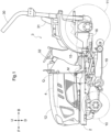
FIG. 4 is a partially cutaway left side view showing a configuration of the connector and so on. -
FIG. 5 is a partially cutaway front view showing a configuration of the connector and so on. -
FIG. 6 is a plan view showing a configuration of a second drain hole and so on. -
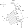
FIG. 7 is a partially cutaway front view showing a configuration of a connecting portion and so on according to a first modification. - An embodiment of the present invention will be described based on the drawings. In the following description, the direction of an arrow F and the direction of an arrow B in the drawings will be respectively referred to as "the front side" and "the rear side", and the direction of an arrow L and the direction of an arrow R in the drawings will be respectively referred to as "the left side" and "the right side" unless otherwise stated. Also, the direction of an arrow U and the direction of an arrow D in the drawings will be respectively referred to as "the upper side" and "the lower side".
- The following describes a tractor according to the present embodiment. As shown in
FIG. 1 , the tractor includes left and rightfront wheels 10, left and rightrear wheels 11, and acover member 12. - The tractor also includes a
body frame 2 and adriving section 3. Thebody frame 2 is supported by the left and rightfront wheels 10 and the left and rightrear wheels 11. - The
cover member 12 is disposed in a front portion of the body of the tractor. Thedriving section 3 is behind thecover member 12. In other words, thecover member 12 is in front of thedriving section 3. - The
driving section 3 includes aprotective frame 30, a driver'sseat 31, and asteering wheel 32. An operator can sit on the driver'sseat 31. Accordingly, the operator can get on thedriving section 3. The operator steers the left and rightfront wheels 10 by operating thesteering wheel 32. The operator can perform various driving operations in thedriving section 3. - The tractor includes a
travel battery 4. Thecover member 12 is configured to be pivotable about an opening/closing axis Q extending in the left-right direction of the body. Accordingly, thecover member 12 is configured to be openable and closable. When thecover member 12 is closed, thetravel battery 4 is covered by thecover member 12. - As shown in
FIG. 2 , the tractor includes aninverter 14 and a motor M. Thetravel battery 4 supplies power to theinverter 14. Theinverter 14 converts DC power supplied from thetravel battery 4 to AC power, and supplies the AC power to the motor M. The motor M is driven by the AC power supplied from theinverter 14. - As shown in
FIGS. 2 and3 , the tractor includes a hydraulic continuouslyvariable transmission 15 and atransmission 16. As shown inFIG. 3 , the hydraulic continuouslyvariable transmission 15 includes ahydraulic pump 15a and ahydraulic motor 15b. - The
hydraulic pump 15a is driven by rotational motive power transmitted from the motor M. As a result of thehydraulic pump 15a being driven, rotational motive power is output from thehydraulic motor 15b. The hydraulic continuouslyvariable transmission 15 is configured to change the speed of rotational motive power between thehydraulic pump 15a and thehydraulic motor 15b. Also, the hydraulic continuouslyvariable transmission 15 is configured to be capable of changing the transmission ratio in a stepless manner. - The rotational motive power output from the
hydraulic motor 15b is transmitted to thetransmission 16. The speed of the rotational motive power transmitted to thetransmission 16 is changed by a gear transmission mechanism included in thetransmission 16, and the rotational motive power is distributed to the left and rightfront wheels 10 and the left and rightrear wheels 11. Thus, the left and rightfront wheels 10 and the left and rightrear wheels 11 are driven. - As shown in
FIGS. 2 and3 , the tractor also includes amiddle PTO shaft 17 and arear PTO shaft 18. Rotational motive power output from the motor M is distributed to thehydraulic pump 15a, themiddle PTO shaft 17, and therear PTO shaft 18. Themiddle PTO shaft 17 and therear PTO shaft 18 are rotated by the distributed rotational motive power. - If a work device is connected to the
middle PTO shaft 17 or therear PTO shaft 18, the work device is driven by rotational motive power transmitted by themiddle PTO shaft 17 or therear PTO shaft 18. For example, in the present embodiment, agrass cutting device 19 is connected to themiddle PTO shaft 17 as shown inFIG. 2 . Thegrass cutting device 19 is driven by rotational motive power transmitted by themiddle PTO shaft 17. - With the above configuration, the tractor according to the present embodiment includes the
travel battery 4, the motor M driven by electric power supplied from thetravel battery 4, the left and rightfront wheels 10 and the left and rightrear wheels 11 driven by the motor M. - Note that this tractor corresponds to the "electric work vehicle" according to the present invention. The
travel battery 4 corresponds to the "battery" according to the present invention. The left and rightfront wheels 10 and the left and rightrear wheels 11 both correspond to the "travel device" according to the present invention. - As shown in
FIGS. 4 to 6 , the tractor according to the present embodiment includes acooling device 20, areserve tank 21, anauxiliary equipment battery 22, avoltage converter 23, and anoil cooler 24. When thecover member 12 is closed, thecooling device 20, thereserve tank 21, theauxiliary equipment battery 22, the voltage converter 23 (DC/DC converter), and theoil cooler 24 are covered by thecover member 12. - The
cooling device 20 includes aradiator 25 and a coolingfan 26. Theradiator 25 and a water pump (not shown) are included in the cooling water path in the tractor. The water pump pumps the cooling water, and the cooling water circulates through this cooling water path. The cooling water is cooled by passing through theradiator 25. Thereserve tank 21 can store cooling water. - The cooling
fan 26 is disposed rearward of theradiator 25. The coolingfan 26 sends cooling air toward the rear side. This allows outside air to be introduced into the inside of thecover member 12 via an outsideair introducing portion 12a provided in a front portion of thecover member 12 and pass through theradiator 25. As a result, theradiator 25 is cooled. - That is to say, the tractor according to the present embodiment includes a
cooling device 20 that includes aradiator 25 and a coolingfan 26 that cools theradiator 25. - The
auxiliary equipment battery 22 supplies electric power to various auxiliary equipment. Also, electric power is sent from thetravel battery 4 to thevoltage converter 23. Thevoltage converter 23 steps down the voltage of the electric power from thetravel battery 4 and supplies it to theauxiliary equipment battery 22. - Hydraulic oil for the tractor is cooled by passing through the
oil cooler 24. - As shown in
FIGS. 4 and6 , thecooling device 20 is supported by asupport frame 40. Thesupport frame 40 is formed in a gate shape that covers left and right portions and an upper portion of theradiator 25. Specifically, thesupport frame 40 includes aleft plate portion 41, anupper plate portion 42, and aright plate portion 43. Both theleft plate portion 41 and theright plate portion 43 are plate-shaped members in a vertical position. Theleft plate portion 41 is disposed on the left of theright plate portion 43. Theupper plate portion 42 is a plate-shaped member in a horizontal position. Theupper plate portion 42 is disposed so as to extend between the upper end portion of theleft plate portion 41 and the upper end portion of theright plate portion 43. Theleft plate portion 41 covers the left portion of theradiator 25. Theupper plate portion 42 covers the upper portion of theradiator 25. Theright plate portion 43 covers the right portion of theradiator 25. - As shown in
FIG. 6 , thevoltage converter 23 is attached to theright plate portion 43 from the right side. Thus, thevoltage converter 23 is supported by thesupport frame 40. - As shown in
FIGS. 4 and6 , thesupport frame 40 is supported by asupport member 45 disposed below thesupport frame 40. Thesupport member 45 is a plate-shaped member in a horizontal position. Thesupport member 45 is supported by thebody frame 2. - As shown in
FIGS. 4 and5 , the tractor according to the present embodiment includes aninput harness 46 and aconnector 47. - An
input unit 48 is disposed on a front side portion of thetravel battery 4. Theconnector 47 is disposed forward of thetravel battery 4 so as to be adjacent to the left end portion of the front end portion of thetravel battery 4. Theinput harness 46 electrically connects theconnector 47 and theinput unit 48. - With this configuration, the
connector 47 is electrically connected to thetravel battery 4 via theinput harness 46 and theinput unit 48. - The
connector 47 is disposed in a side portion of the body so as to face the side of the body. More specifically, theconnector 47 is disposed in a left side portion of the body so as to face the left side of the body. More precisely, theconnector 47 is oriented toward the upper left of the body. - As shown in
FIGS. 4 and5 , theconnector 47 includes aconnection terminal 50 and ahousing 51. Theconnection terminal 50 is electrically connected to thetravel battery 4 via theinput harness 46 and theinput unit 48. Acharger 60 provided at a charging facility or the like can be connected to theconnection terminal 50. Note that the standards of thecharger 60 and theconnector 47 are not particularly limited, and may be, for example, CHAdeMO. - By connecting the
charger 60 to theconnection terminal 50, electric power is supplied to thetravel battery 4 via theinput harness 46 and theinput unit 48. Thus, thetravel battery 4 is charged. - In this way, the tractor according to the present embodiment includes a
connector 47 to which thecharger 60 is connectable and that is electrically connected to thetravel battery 4. - As shown in
FIG. 4 , when thecover member 12 is open, theconnector 47 does not overlap thecover member 12 in a side view. That is to say, when thecover member 12 is open, theconnector 47 is exposed. When thecover member 12 is closed, theconnector 47 is covered by thecover member 12. Note that inFIG. 4 , thecover member 12 in the open state is indicated by imaginary lines. Thecover member 12 in the closed state is indicated by solid lines. - As shown in
FIGS. 4 to 6 , thehousing 51 has a substantially cylindrical shape. Thehousing 51 is disposed so as to enclose theconnection terminal 50. Thus, thehousing 51 covers theconnection terminal 50. - That is to say, the
connector 47 includes aconnection terminal 50 to which thecharger 60 is connectable and ahousing 51 that covers theconnection terminal 50. - As shown in
FIGS. 4 and5 , the tractor according to the present embodiment includes a bent plate-shaped holdingportion 52 and asupport stay 53. Thehousing 51 passes through a mountingopening 52a of the holdingportion 52 and is fixed to the holdingportion 52 with bolts. - As shown in
FIG. 4 , the holdingportion 52 is fixed to the support stay 53 with bolts. The support stay 53 extends in the front-rear direction. The front end portion of thesupport stay 53 is fixed to theleft plate portion 41 with bolts. The rear end portion of thesupport stay 53 is fixed to thetravel battery 4 with bolts. - With the above-described configuration, the
housing 51 is supported by theleft plate portion 41 and thetravel battery 4 by means of the holdingportion 52 and thesupport stay 53. As a result, thehousing 51 is supported by thesupport member 45 by means of the holdingportion 52, thesupport stay 53, and theleft plate portion 41. As shown inFIGS. 4 to 6 , thesupport member 45 is disposed below thehousing 51. - In this way, the tractor according to the present embodiment includes a
support member 45 that is disposed below thehousing 51 and supports thehousing 51. - As shown in
FIG. 6 , thehousing 51 is disposed so as to overlap the coolingfan 26 of thecooling device 20 in a plan view. However, the present invention is not limited to such a configuration, and thehousing 51 may be disposed adjacent to thecooling device 20 without overlapping thecooling device 20 in a plan view. - In this way, the
housing 51 is disposed so as to be adjacent to thecooling device 20 or so as to overlap thecooling device 20 in a plan view. - As shown in
FIG. 5 , thehousing 51 includes anopening 51a configured to receive thecharger 60. Thehousing 51 is oriented with theopening 51a facing diagonally upward. - That is to say, the
housing 51 includes anopening 51a configured to receive thecharger 60 and is oriented with theopening 51a facing diagonally upward. - A shown in
FIGS. 4 and5 , anoutput unit 49 is disposed on a front side portion of thetravel battery 4. Theoutput unit 49 is arranged adjacent to the left side of theinput unit 48. Theoutput unit 49 is electrically connected to aninverter 14 via anoutput harness 54. - The electric power from the
travel battery 4 is supplied to theinverter 14 via theoutput unit 49 and theoutput harness 54. - As shown in
FIG. 5 , thehousing 51 includes acylindrical portion 51b extending diagonally downward to the left. Afirst drain hole 61 is formed in a lower portion of thehousing 51. Thefirst drain hole 61 is located at a position lower than a lower end position P1 of theopening 51a. - The
first drain hole 61 is a hole extending from aninlet port 61a to anoutlet port 61b. Theinlet port 61a is located at the lower end portion of the space in thehousing 51 in which thecharger 60 is received. Theoutlet port 61b is located at the lower end portion of thecylindrical portion 51b. That is to say, a portion of thefirst drain hole 61 passes through thecylindrical portion 51b. Theoutlet port 61b is located at a position lower than theinlet port 61a. - With this configuration, when water enters the space in the
housing 51 in which thecharger 60 is received, the water enters thefirst drain hole 61 from theinlet port 61a due to gravity. Thereafter, the water moves downward through thefirst drain hole 61 due to gravity and is discharged downward from theoutlet port 61b. - As shown in
FIGS. 5 and6 , asecond drain hole 45a is formed in thesupport member 45. As shown inFIG. 6 , thesecond drain hole 45a overlaps thehousing 51 in a plan view. Thesecond drain hole 45a is located between the coolingdevice 20 and theoil cooler 24 in a plan view. - With this configuration, water discharged downward from the
outlet port 61b falls onto thesupport member 45. The water that has fallen on thesupport member 45 is easily evaporated by the heat from theradiator 25 and the air from the coolingfan 26. Even if the water that has fallen on thesupport member 45 does not evaporate, it is likely to be drained downward by gravity from thesecond drain hole 45a. - Note that the tractor according to the present embodiment is configured so that there is no member directly below the
second drain hole 45a. Therefore, the water discharged downward from thesecond drain hole 45a falls to the ground. - With the configuration described above, even if water enters the
housing 51, the water is discharged to the outside of thehousing 51 by gravity from thefirst drain hole 61 in the lower portion of thehousing 51. This makes it difficult for water to accumulate inside thehousing 51. This will likely eliminate the need to remove water from thehousing 51 prior to connecting thecharger 60. Therefore, the labor required to operate the tractor can be reduced. - Thus, the configuration described above can realize a tractor capable of reducing the labor required to operate the tractor.
- The
cylindrical portion 51b is provided in the above-described embodiment. A portion of thefirst drain hole 61 passes through thecylindrical portion 51b. - However, the present invention is not limited to such a configuration. Hereinafter, a first modification of the present invention will be described, focusing on the points that are different from the above embodiment. The configurations of components other than those described below are the same as in the above embodiment. The same reference signs are used for the same components as in the above embodiment.
- As shown in
FIG. 7 , thecylindrical portion 51b is not provided in the first modification. Instead of thefirst drain hole 61, at least one of athird drain hole 62, afourth drain hole 63, and afifth drain hole 64 is provided. InFIG. 7 , thethird drain hole 62, thefourth drain hole 63, and thefifth drain hole 64 are indicated by imaginary lines. - Note that only one, only two, or all of the
third drain hole 62, thefourth drain hole 63, and thefifth drain hole 64 may be provided. - The
third drain hole 62, thefourth drain hole 63, and thefifth drain hole 64 are all formed in the lower portion of thehousing 51 and are located at positions lower than the lower end position P1 of theopening 51a. Thethird drain hole 62, thefourth drain hole 63, and thefifth drain hole 64 all correspond to the "first drain hole" according to the present invention. - The
third drain hole 62 is located near theopening 51a in the lower portion of thehousing 51. Thefourth drain hole 63 is located in the lower portion of thehousing 51 at a position that is in communication with the lower end portion of the space in which thecharger 60 is received. Thefifth drain hole 64 is located below thefourth drain hole 63. If thefourth drain hole 63 and thefifth drain hole 64 are provided, water discharged downward through thefourth drain hole 63 is further discharged downward through thefifth drain hole 64. - Even with such a configuration, for example, if the
housing 51 and thecooling device 20 are arranged so that the water discharged through thethird drain hole 62 or thefifth drain hole 64 falls to a position near thecooling device 20, the water falling on thesupport member 45 is easily evaporated by the heat from theradiator 25 and the air from the coolingfan 26. In addition, if thesecond drain hole 45a overlaps thehousing 51 in a plan view, the water falling on thesupport member 45 through thethird drain hole 62 or thefifth drain hole 64, even if it does not evaporate, is easily discharged downward through thesecond drain hole 45a by gravity. -
- (1) The
second drain hole 45a need not be formed in thesupport member 45. - (2) The
second drain hole 45a need not overlap thehousing 51 in a plan view. - (3) The
housing 51 need not be disposed so as to be adjacent to thecooling device 20 or so as to overlap thecooling device 20 in a plan view. - (4) The
opening 51a need not face diagonally upward. - (5) The
first drain hole 61 may be located at a position higher than the lower end position P1 of theopening 51a. - Note that the configurations disclosed in the above embodiments (including the modification, the same applies hereinafter) are applicable in combination with the configurations disclosed in the other embodiments as long as no contradiction occurs. In addition, the embodiments disclosed in this specification are illustrative, and the embodiments of the present invention are not limited thereto, and can be modified as appropriate without departing from the purpose of the present invention.
- The present invention is applicable not only to tractors but also to various electric work vehicles such as combines, rice transplanters, and construction machines.
-
- 4: Travel Battery (Battery)
- 10: Front Wheel (Travel Device)
- 11: Rear Wheel (Travel Device)
- 20: Cooling Device
- 25: Radiator
- 26: Cooling Fan
- 45: Support Member
- 45a: Second Drain Hole
- 47: Connector
- 50: Connection Terminal
- 51: Housing
- 51a: Opening
- 60: Charger
- 61: First Drain Hole
- 62: Third Drain Hole (First Drain Hole)
- 63: Fourth Drain Hole (First Drain Hole)
- 64: Fifth Drain Hole (First Drain Hole)
- M: Motor
- P1: Lower End Position
Claims (4)
- An electric work vehicle comprising:a battery;a motor configured to be driven by electric power supplied from the battery;a travel device configured to be driven by the motor; anda connector to which a charger is connectable and is electrically connected to the battery,wherein the connector includes a connection terminal to which the charger is connectable and a housing that covers the connection terminal, andthe housing includes a first drain hole in a lower portion thereof.
- The electric work vehicle according to claim 1, further comprising:a support member disposed below the housing and supporting the housing,wherein the support member includes a second drain hole, andthe second drain hole overlaps the housing in a plan view.
- The electric work vehicle according to claim 1 or 2, further comprising:a cooling device that includes a radiator and a cooling fan configured to cool the radiator,wherein the housing is disposed so as to be adjacent to the cooling device or so as to overlap the cooling device in a plan view.
- The electric work vehicle according to any one of claims 1 to 3,wherein the housing includes an opening configured to receive the charger, and is oriented with the opening facing diagonally upward, andthe first drain hole is located at a position lower than a lower end position of the opening.
Applications Claiming Priority (2)
| Application Number | Priority Date | Filing Date | Title |
|---|---|---|---|
| JP2021211642A JP7675643B2 (en) | 2021-12-24 | 2021-12-24 | electric work vehicle |
| PCT/JP2022/044538 WO2023120113A1 (en) | 2021-12-24 | 2022-12-02 | Electric work vehicle |
Publications (2)
| Publication Number | Publication Date |
|---|---|
| EP4456369A1 true EP4456369A1 (en) | 2024-10-30 |
| EP4456369A4 EP4456369A4 (en) | 2025-12-24 |
Family
ID=86902132
Family Applications (1)
| Application Number | Title | Priority Date | Filing Date |
|---|---|---|---|
| EP22910830.3A Pending EP4456369A4 (en) | 2021-12-24 | 2022-12-02 | ELECTRIC WORK VEHICLE |
Country Status (4)
| Country | Link |
|---|---|
| US (1) | US20240326618A1 (en) |
| EP (1) | EP4456369A4 (en) |
| JP (1) | JP7675643B2 (en) |
| WO (1) | WO2023120113A1 (en) |
Families Citing this family (3)
| Publication number | Priority date | Publication date | Assignee | Title |
|---|---|---|---|---|
| JP7498683B2 (en) * | 2021-06-29 | 2024-06-12 | 株式会社クボタ | Electric work vehicle |
| JP2024136650A (en) * | 2023-03-24 | 2024-10-04 | 株式会社オートネットワーク技術研究所 | connector |
| JP2025035862A (en) | 2023-09-04 | 2025-03-14 | 株式会社クボタ | Work vehicle |
Family Cites Families (8)
| Publication number | Priority date | Publication date | Assignee | Title |
|---|---|---|---|---|
| JP5974637B2 (en) | 2012-05-30 | 2016-08-23 | 井関農機株式会社 | Electric work vehicle |
| JP5648032B2 (en) * | 2012-09-06 | 2015-01-07 | 本田技研工業株式会社 | Vehicle connection protection structure |
| WO2014147763A1 (en) | 2013-03-19 | 2014-09-25 | 住友電装株式会社 | Vehicle-side connector |
| JP2018166381A (en) | 2017-03-28 | 2018-10-25 | 三菱自動車工業株式会社 | Electric work vehicle |
| JP6764453B2 (en) * | 2018-09-27 | 2020-09-30 | 本田技研工業株式会社 | Body front structure |
| CN111114355B (en) | 2018-10-31 | 2022-08-09 | 比亚迪股份有限公司 | Charging port of integrated heat dissipation system |
| IT201900006855A1 (en) * | 2019-05-15 | 2020-11-15 | Autotest Suedtirol Srl | Locking module with a flap for closing a refueling area of a vehicle in particular an electric vehicle |
| JP7321008B2 (en) * | 2019-06-24 | 2023-08-04 | 株式会社クボタ | electric work vehicle |
-
2021
- 2021-12-24 JP JP2021211642A patent/JP7675643B2/en active Active
-
2022
- 2022-12-02 WO PCT/JP2022/044538 patent/WO2023120113A1/en not_active Ceased
- 2022-12-02 EP EP22910830.3A patent/EP4456369A4/en active Pending
-
2024
- 2024-06-05 US US18/734,651 patent/US20240326618A1/en active Pending
Also Published As
| Publication number | Publication date |
|---|---|
| US20240326618A1 (en) | 2024-10-03 |
| JP2023095634A (en) | 2023-07-06 |
| EP4456369A4 (en) | 2025-12-24 |
| WO2023120113A1 (en) | 2023-06-29 |
| JP7675643B2 (en) | 2025-05-13 |
Similar Documents
| Publication | Publication Date | Title |
|---|---|---|
| EP4456369A1 (en) | Electric work vehicle | |
| EP2799322A1 (en) | Saddle-type electric vehicle | |
| EP4534309A1 (en) | Work vehicle | |
| EP4534316A1 (en) | Work vehicle | |
| EP4527657A1 (en) | Work vehicle | |
| US20250108711A1 (en) | Work vehicle | |
| EP4530121A1 (en) | Agricultural work vehicle | |
| EP4529752A1 (en) | Agricultural tractor | |
| EP4530112A1 (en) | Work vehicle | |
| US12409740B2 (en) | Electric work vehicle | |
| US20240326611A1 (en) | Electric work vehicle | |
| US20250108708A1 (en) | Work vehicle | |
| JP7546543B2 (en) | Electric work vehicle | |
| EP4450310A1 (en) | Electric work vehicle | |
| EP4534314A1 (en) | Work vehicle | |
| EP4454913A1 (en) | Electric work vehicle | |
| EP4454914A1 (en) | Electric work vehicle | |
| JP7555326B2 (en) | Electric work vehicle | |
| EP4530105A1 (en) | Work vehicle | |
| EP4737177A1 (en) | Work vehicle | |
| JP2024164319A5 (en) |
Legal Events
| Date | Code | Title | Description |
|---|---|---|---|
| STAA | Information on the status of an ep patent application or granted ep patent |
Free format text: STATUS: THE INTERNATIONAL PUBLICATION HAS BEEN MADE |
|
| PUAI | Public reference made under article 153(3) epc to a published international application that has entered the european phase |
Free format text: ORIGINAL CODE: 0009012 |
|
| STAA | Information on the status of an ep patent application or granted ep patent |
Free format text: STATUS: REQUEST FOR EXAMINATION WAS MADE |
|
| 17P | Request for examination filed |
Effective date: 20240606 |
|
| AK | Designated contracting states |
Kind code of ref document: A1 Designated state(s): AL AT BE BG CH CY CZ DE DK EE ES FI FR GB GR HR HU IE IS IT LI LT LU LV MC ME MK MT NL NO PL PT RO RS SE SI SK SM TR |
|
| DAV | Request for validation of the european patent (deleted) | ||
| DAX | Request for extension of the european patent (deleted) | ||
| A4 | Supplementary search report drawn up and despatched |
Effective date: 20251125 |
|
| RIC1 | Information provided on ipc code assigned before grant |
Ipc: H02J 7/00 20060101AFI20251119BHEP Ipc: B60L 53/14 20190101ALI20251119BHEP Ipc: B60K 1/04 20190101ALI20251119BHEP Ipc: H01R 13/52 20060101ALI20251119BHEP Ipc: B60K 1/00 20060101ALI20251119BHEP Ipc: B60K 11/02 20060101ALI20251119BHEP Ipc: B60K 15/05 20060101ALN20251119BHEP |