EP4456335A1 - Insertion terminal and insertion terminal mounting structure - Google Patents
Insertion terminal and insertion terminal mounting structure Download PDFInfo
- Publication number
- EP4456335A1 EP4456335A1 EP22910119.1A EP22910119A EP4456335A1 EP 4456335 A1 EP4456335 A1 EP 4456335A1 EP 22910119 A EP22910119 A EP 22910119A EP 4456335 A1 EP4456335 A1 EP 4456335A1
- Authority
- EP
- European Patent Office
- Prior art keywords
- plug
- terminal
- fixing
- laminate base
- disposed
- Prior art date
- Legal status (The legal status is an assumption and is not a legal conclusion. Google has not performed a legal analysis and makes no representation as to the accuracy of the status listed.)
- Granted
Links
Images




Classifications
-
- H—ELECTRICITY
- H01—ELECTRIC ELEMENTS
- H01R—ELECTRICALLY-CONDUCTIVE CONNECTIONS; STRUCTURAL ASSOCIATIONS OF A PLURALITY OF MUTUALLY-INSULATED ELECTRICAL CONNECTING ELEMENTS; COUPLING DEVICES; CURRENT COLLECTORS
- H01R13/00—Details of coupling devices of the kinds covered by groups H01R12/70 or H01R24/00 - H01R33/00
- H01R13/40—Securing contact members in or to a base or case; Insulating of contact members
- H01R13/42—Securing in a demountable manner
- H01R13/424—Securing in base or case composed of a plurality of insulating parts having at least one resilient insulating part
-
- H—ELECTRICITY
- H01—ELECTRIC ELEMENTS
- H01R—ELECTRICALLY-CONDUCTIVE CONNECTIONS; STRUCTURAL ASSOCIATIONS OF A PLURALITY OF MUTUALLY-INSULATED ELECTRICAL CONNECTING ELEMENTS; COUPLING DEVICES; CURRENT COLLECTORS
- H01R13/00—Details of coupling devices of the kinds covered by groups H01R12/70 or H01R24/00 - H01R33/00
- H01R13/02—Contact members
- H01R13/10—Sockets for co-operation with pins or blades
- H01R13/11—Resilient sockets
-
- H—ELECTRICITY
- H01—ELECTRIC ELEMENTS
- H01R—ELECTRICALLY-CONDUCTIVE CONNECTIONS; STRUCTURAL ASSOCIATIONS OF A PLURALITY OF MUTUALLY-INSULATED ELECTRICAL CONNECTING ELEMENTS; COUPLING DEVICES; CURRENT COLLECTORS
- H01R13/00—Details of coupling devices of the kinds covered by groups H01R12/70 or H01R24/00 - H01R33/00
- H01R13/02—Contact members
- H01R13/10—Sockets for co-operation with pins or blades
- H01R13/11—Resilient sockets
- H01R13/112—Resilient sockets forked sockets having two legs
-
- H—ELECTRICITY
- H01—ELECTRIC ELEMENTS
- H01R—ELECTRICALLY-CONDUCTIVE CONNECTIONS; STRUCTURAL ASSOCIATIONS OF A PLURALITY OF MUTUALLY-INSULATED ELECTRICAL CONNECTING ELEMENTS; COUPLING DEVICES; CURRENT COLLECTORS
- H01R13/00—Details of coupling devices of the kinds covered by groups H01R12/70 or H01R24/00 - H01R33/00
- H01R13/02—Contact members
- H01R13/10—Sockets for co-operation with pins or blades
- H01R13/11—Resilient sockets
- H01R13/113—Resilient sockets co-operating with pins or blades having a rectangular transverse section
-
- H—ELECTRICITY
- H01—ELECTRIC ELEMENTS
- H01R—ELECTRICALLY-CONDUCTIVE CONNECTIONS; STRUCTURAL ASSOCIATIONS OF A PLURALITY OF MUTUALLY-INSULATED ELECTRICAL CONNECTING ELEMENTS; COUPLING DEVICES; CURRENT COLLECTORS
- H01R13/00—Details of coupling devices of the kinds covered by groups H01R12/70 or H01R24/00 - H01R33/00
- H01R13/02—Contact members
- H01R13/10—Sockets for co-operation with pins or blades
- H01R13/11—Resilient sockets
- H01R13/115—U-shaped sockets having inwardly bent legs, e.g. spade type
-
- H—ELECTRICITY
- H01—ELECTRIC ELEMENTS
- H01R—ELECTRICALLY-CONDUCTIVE CONNECTIONS; STRUCTURAL ASSOCIATIONS OF A PLURALITY OF MUTUALLY-INSULATED ELECTRICAL CONNECTING ELEMENTS; COUPLING DEVICES; CURRENT COLLECTORS
- H01R13/00—Details of coupling devices of the kinds covered by groups H01R12/70 or H01R24/00 - H01R33/00
- H01R13/02—Contact members
- H01R13/20—Pins, blades, or sockets shaped, or provided with separate member, to retain co-operating parts together
-
- H—ELECTRICITY
- H01—ELECTRIC ELEMENTS
- H01R—ELECTRICALLY-CONDUCTIVE CONNECTIONS; STRUCTURAL ASSOCIATIONS OF A PLURALITY OF MUTUALLY-INSULATED ELECTRICAL CONNECTING ELEMENTS; COUPLING DEVICES; CURRENT COLLECTORS
- H01R13/00—Details of coupling devices of the kinds covered by groups H01R12/70 or H01R24/00 - H01R33/00
- H01R13/02—Contact members
- H01R13/22—Contacts for co-operating by abutting
- H01R13/24—Contacts for co-operating by abutting resilient; resiliently-mounted
- H01R13/2457—Contacts for co-operating by abutting resilient; resiliently-mounted consisting of at least two resilient arms contacting the same counterpart
-
- H—ELECTRICITY
- H01—ELECTRIC ELEMENTS
- H01R—ELECTRICALLY-CONDUCTIVE CONNECTIONS; STRUCTURAL ASSOCIATIONS OF A PLURALITY OF MUTUALLY-INSULATED ELECTRICAL CONNECTING ELEMENTS; COUPLING DEVICES; CURRENT COLLECTORS
- H01R13/00—Details of coupling devices of the kinds covered by groups H01R12/70 or H01R24/00 - H01R33/00
- H01R13/02—Contact members
- H01R13/22—Contacts for co-operating by abutting
- H01R13/24—Contacts for co-operating by abutting resilient; resiliently-mounted
- H01R13/2464—Contacts for co-operating by abutting resilient; resiliently-mounted characterized by the contact point
- H01R13/2492—Contacts for co-operating by abutting resilient; resiliently-mounted characterized by the contact point multiple contact points
-
- H—ELECTRICITY
- H01—ELECTRIC ELEMENTS
- H01R—ELECTRICALLY-CONDUCTIVE CONNECTIONS; STRUCTURAL ASSOCIATIONS OF A PLURALITY OF MUTUALLY-INSULATED ELECTRICAL CONNECTING ELEMENTS; COUPLING DEVICES; CURRENT COLLECTORS
- H01R13/00—Details of coupling devices of the kinds covered by groups H01R12/70 or H01R24/00 - H01R33/00
- H01R13/40—Securing contact members in or to a base or case; Insulating of contact members
-
- H—ELECTRICITY
- H01—ELECTRIC ELEMENTS
- H01R—ELECTRICALLY-CONDUCTIVE CONNECTIONS; STRUCTURAL ASSOCIATIONS OF A PLURALITY OF MUTUALLY-INSULATED ELECTRICAL CONNECTING ELEMENTS; COUPLING DEVICES; CURRENT COLLECTORS
- H01R31/00—Coupling parts supported only by co-operation with counterpart
- H01R31/06—Intermediate parts for linking two coupling parts, e.g. adapter
-
- H—ELECTRICITY
- H01—ELECTRIC ELEMENTS
- H01R—ELECTRICALLY-CONDUCTIVE CONNECTIONS; STRUCTURAL ASSOCIATIONS OF A PLURALITY OF MUTUALLY-INSULATED ELECTRICAL CONNECTING ELEMENTS; COUPLING DEVICES; CURRENT COLLECTORS
- H01R13/00—Details of coupling devices of the kinds covered by groups H01R12/70 or H01R24/00 - H01R33/00
- H01R13/40—Securing contact members in or to a base or case; Insulating of contact members
- H01R13/42—Securing in a demountable manner
- H01R13/422—Securing in resilient one-piece base or case, e.g. by friction; One-piece base or case formed with resilient locking means
- H01R13/4223—Securing in resilient one-piece base or case, e.g. by friction; One-piece base or case formed with resilient locking means comprising integral flexible contact retaining fingers
- H01R13/4226—Securing in resilient one-piece base or case, e.g. by friction; One-piece base or case formed with resilient locking means comprising integral flexible contact retaining fingers comprising two or more integral flexible retaining fingers acting on a single contact
Definitions
- the present disclosure relates to the technical field of electrical connections, and particularly to a plug-in terminal and a plug-in terminal mounting structure.
- contacts are key components of connectors.
- Most of the existing terminals are formed by machining, which not only leads to a high cost and a low production efficiency, but also has a limited current carrying capacity.
- a sheet terminal With the same contact area and current carrying capacity, owing to the processing mode, a sheet terminal is not only far lower in cost and weight than a circular terminal, but also has a good current carrying capacity, and it is the mainstream development trend of the future connector industry.
- most of the existing sheet terminals are fixed by welding, which is difficult for later maintenance at certain extent.
- the present disclosure aims to provide a plug-in terminal and a plug-in terminal mounting structure, in which a plurality of sheet-like laminated terminals are assembled together, and a contact portion and a cantilever are disposed on a plug-in arm, thereby increasing the contact area between the laminated terminal and a mating terminal.
- This design not only achieves a strong current carrying capacity, but also enables the plug-in terminal to be conveniently assembled, so that the whole structure is simple and the maintenance cost is low.
- An embodiment of a first aspect of the present disclosure provides a plug-in terminal, comprising a plurality of laminated terminals stacked in a transverse direction, each of the laminated terminals includes: a laminate base body and plug-in arms longitudinally extending from one end of the laminate base body and disposed to be paired, with a plug-in space formed between the paired plug-in arms; a contact portion protruding toward the plug-in space and a protruding cantilever with elastic are sequentially disposed from a free end of the plug-in arm to the laminate base body; a plurality of the plug-in spaces are stacked in the transverse direction to form a plug-in groove , the plug-in groove is configured to interface with a mating terminal to realize an electrical connection between the plug-in terminal and the mating terminal.
- each of the laminated terminals further includes the plug-in arms extending longitudinally from the other end of the laminate base body and disposed to be paired.
- the contact portions in the laminated terminal are symmetrically disposed.
- the cantilevers in the laminated terminal are symmetrically disposed.
- the cantilever extends from a free end of the plug-in arm toward the laminate base body.
- a bent portion is disposed on a side at the free end of the cantilever, and an outer side of the bent portion faces the plug-in space.
- a minimum distance between the bent portions is less than or equal to a minimum distance between the contact portions.
- each of the laminate base bodies includes at least one pair of buckle recesses which are oppositely disposed; the buckle recesses of the plurality of laminate base bodies are stacked in the transverse direction to form a corresponding buckle groove;
- the plug-in terminal further includes at least one pair of first buckles, each of which includes a fixing portion and holding portions disposed at two ends of the fixing portion; the fixing portions of one pair of the first buckles are respectively buckled in the corresponding buckle grooves, and the holding portions of at least one pair of the first buckles are mutually clamped to fix the plurality of laminated terminals together.
- the plug-in terminal further includes a pair of second buckles, each of which includes a fixing portion and holding portions disposed at two ends of the fixing portion, in which the fixing portion has a hollow structure that divides the fixing portion into a first fixing portion and a second fixing portion which are respectively buckled in the corresponding buckle grooves, and the holding portions on the same side of one pair of the second buckles are clamped with each other to fix the plurality of laminated terminals together, and in which the fixing groove is exposed through the hollow structure.
- An embodiment of a second aspect of the present disclosure provides a plug-in terminal mounting structure, comprising fixing sidewalls which are oppositely disposed and the plug-in terminal according to the embodiment of the first aspect, in which inner sides of the fixing sidewalls are respectively provided with extended elastic pieces, ends of the elastic pieces are respectively provided with protruding fixing blocks, and the fixing blocks are cooperatively connected to the fixing groove.
- an embodiment of a first aspect of the present disclosure provides a plug-in terminal 100, which includes a plurality of laminated terminals 10 stacked in a transverse direction, each of the laminated terminals 10 includes a laminate base body 11 and plug-in arms 12 longitudinally extending from one end of the laminate base body 11 and disposed to be paired, such as two oppositely disposed plug-in arms 12, with a plug-in space 13 formed between the paired plug-in arms 12; a contact portion 121 protruding toward the plug-in space 13 and a protruding cantilever with elastic 122 are sequentially disposed from a free end of the plug-in arm 12 to the laminate base body 11; the plug-in spaces 13 are stacked in the transverse direction to form a plug-in groove 23, the plug-in groove 23 is configured to interface with a mating terminal 200 ( FIG. 13 ) to realize an electrical connection between the plug-in terminal 100 and the mating terminal 200; and the transverse direction is a stacking
- the plug-in arm 12 of each of the laminated terminals 10 of the plug-in terminal 100 is provided with the cantilever 122, which increases contact points between the plug-in terminal 100 and the mating terminal 200 and then increases the contact area between the plug-in terminal 100 and the mating terminal 200.
- the plug-in terminal 100 is composed of a plurality of the laminated terminals 10, which can ensure a stable clamping structure, reduce the deformation and increase the strength of the plug-in arm 12.
- each of the laminated terminals 10 further includes the plug-in arms 12 extending longitudinally from the other end of the laminate base body 11 and disposed to be paired, such as another two oppositely disposed plug-in arms 12.
- the plug-in arms 12 By disposing the plug-in arms 12 on the two ends of the laminate base 11 respectively, the laminated terminal 10 can be plugged with the mating terminal 200 in two opposite directions.
- the laminated terminal 10 may be formed by be punching or cutting a plate and has a sheet shape.
- the laminated terminals 10 are distributed in a stacked state in the plug-in terminal 100, so that the plug-in terminal 100 has a high mechanical connection performance, while ensuring the conductive connection performance between the plug-in terminal 100 and the mating terminal 200.
- the punching or cutting of the plate is simple and the process is mature, so that the laminated terminals 10 can be quickly machined in large quantities, thereby saving the machining cost and improving the production efficiency.
- the mating terminal 200 cooperated with the plug-in terminal 100 may have a sheet shape or a plate shape.
- the clamping force can be controlled to facilitate the match with the mating terminal 200 and meet various plug-in requirements.
- the plug-in arms 12 By disposing the plug-in arms 12 of different sizes, it is possible to adapt to the mating terminals 200 of different shapes.
- the contact portions 121 in the laminated terminal 10 are symmetrically disposed. Therefore, when the mating terminal 200 is plugged into the plug-in groove 23, the stresses on both sides of the mating terminal 200 are corresponding to each other to achieve a better clamping effect.
- the cantilevers 122 in the laminated terminal 10 are symmetrically disposed. Therefore, when the mating terminal 200 is plugged into the plug-in groove 23, the stresses on both sides of the mating terminal 200 are corresponding to each other to achieve a better clamping effect.
- the cantilever 122 extends from a free end of the plug-in arm 12 toward the laminate base body 11.
- a direction in which the cantilever 122 extends from the free end of the plug-in arm 12 toward the laminate base body 11 is a direction in which the mating terminal 200 is plugged into the plug groove 23. Therefore, in practical application, the failure of the cantilever 122 caused by the oblique plug-in of the mating terminal 200 is avoided, thereby avoiding the poor electrical contact between the plug-in terminal 100 and the mating terminal 200.
- a bent portion 1221 is disposed on a side at the free end of the cantilever 122, and an outer side of the bent portion 1221 faces the plug-in space 13.
- the clamping force of the laminated terminal 10 to the mating terminal 200 can be increased when the plug-in terminal 100 is plugged into the mating terminal 200.
- the outer side of the bent portion 1221 is a protruding side.
- a minimum distance between the bent portions 1221 on the paired plug-in arms 12 is less than or equal to a minimum distance between the contact portions 121 on the paired plug-in arms 12.
- a minimum distance between two opposite bent portions 1221 in a free state is less than or equal to a minimum distance between two opposite contact portions 121 in a free state, so that the cantilever 122 can generate a better clamping force for the mating terminal 200 when the mating terminal 200 is plugged into the plug-in groove 23.
- each of the laminate base bodies 11 includes at least one pair of buckle recesses 14 which are oppositely disposed.
- the buckle recesses 14 of the plurality of laminate base bodies 11 are stacked in the transverse direction to form corresponding buckle grooves 24.
- the plug-in terminal 100 further includes at least one pair of first buckles 30. As illustrated in FIG.
- the first buckle 30 includes a fixing portion 301 and holding portions 302 disposed at two ends of the fixing portion 301; the fixing portions 301 of one pair of the first buckles 30 are respectively buckled in the corresponding buckle grooves 24, and the holding portions 302 of at least one pair of the first buckles 30 are mutually clamped to fix the plurality of laminated terminals 10 together.
- one pair of the first buckles 30 may be cooperated with the plug-in terminal with one pair of the buckle grooves 24, or as illustrated in FIG. 6 , the plug-in terminal 100 includes two pairs of buckle grooves 24, with which two pairs of first buckles 30 are cooperated respectively to fix the plurality of laminated terminals 10 together.
- the first buckle 30 is made of a plastic material or any other hard material.
- the plug-in arm 12 when the mating terminal 200 is plugged into the plug-in terminal 100, the plug-in arm 12 stretches, and a tension on the laminate base body 11 will be transferred through the first buckle 30. By disposing the first buckle 30, the plug-in arm 12 can be supported to avoid the failure of the plug-in terminal 100 caused by excessive plug-in and unplug-in of the mating terminal 200.
- each of the laminate base bodies 11 are respectively provided with opposite buckle recesses 14.
- buckle recesses 14 of the plurality of laminate base bodies 11 are stacked in the transverse direction to form the corresponding buckle grooves 24
- a fixing recess 15 is further disposed between the buckle recesses 14 at the two ends of each of the laminate base bodies 11, and the fixing recesses 15 of the plurality of laminate base bodies 11 are stacked in the transverse direction to form a fixing groove 25.
- the plug-in terminal 100 further includes a pair of second buckles 31, each of which includes a fixing portion 301 and holding portions 302 disposed at two ends of the fixing portion 301, in which the fixing portion 301 has a hollow structure 32 that divides the fixing portion 301 into a first fixing portion 311 and a second fixing portion 312 which are respectively buckled in the corresponding buckle grooves 24, and the holding portions 302 on the same side of one pair of the second buckles 31 are clamped with each other to fix the plurality of laminated terminals 10 together, and in which the fixing groove 25 is exposed through the hollow structure 32.
- the second buckle 31 is made of a plastic material or any other hard material.
- An embodiment of a second aspect of the present disclosure provides a plug-in terminal mounting structure, including fixing sidewalls 40 which are oppositely disposed and a plug-in terminal 100, in which inner sides of the fixing sidewall 40 are respectively provided with extended elastic pieces 41, ends of the elastic pieces 41 are respectively provided with protruding fixing blocks 42, and the fixing blocks 42 are cooperatively connected to the fixing groove 25.
- the elastic piece 41 contracts, so that the fixing groove 25 also contracts, thereby fixing and supporting the plug-in terminal 100.
- the plug-in terminal 100 is cooperated with the fixing block 42 of the elastic piece 41, and is detachable during mounting due to the elastic effect of the elastic piece 41. In the directions as illustrated in FIGS. 11 and 12 , the plug-in terminal 100 is mounted to the fixing sidewall 40 from bottom to top, and the plug-in terminal 100 can be easily plugged between two opposite fixing sidewalls 40 due to the elastic effect of the elastic piece 41, so that the fixing block 42 can be successfully plugged into the fixing groove 25, thereby saving the cost of the later maintenance.
- the plug-in terminal 100 As illustrated in FIGS. 13 to 15 , after the plug-in terminal 100 is mounted on an insulator, it can be plugged into the mating terminal 200 in the directions of 90° and 180°, and a plug-in direction is from top to bottom, thereby achieving the adaption with the high-current mating terminal 200.
- a term such as “mount”, “connect”, “fix” or the like should be broadly understood, and for example, it may be a fixed connection, a detachable connection, an integration, a mechanical connection, an electrical connection, a direct connection, an indirect connection through an intermediate medium, or a communication between the interiors of two elements, or an interactive relationship between two elements.
- mount e.g., a fixed connection
- detachable connection e.g., it may be a fixed connection, a detachable connection, an integration, a mechanical connection, an electrical connection, a direct connection, an indirect connection through an intermediate medium, or a communication between the interiors of two elements, or an interactive relationship between two elements.
Landscapes
- Connector Housings Or Holding Contact Members (AREA)
Abstract
Description
- The present disclosure claims the priority of a Chinese utility model patent application with an application number of
202123264258.7, a patent title of "insertion terminal and insertion terminal mounting structure" and filed on December 23, 2021 - The present disclosure relates to the technical field of electrical connections, and particularly to a plug-in terminal and a plug-in terminal mounting structure.
- In the practical application of a high voltage connector, contacts are key components of connectors. Most of the existing terminals are formed by machining, which not only leads to a high cost and a low production efficiency, but also has a limited current carrying capacity. With the same contact area and current carrying capacity, owing to the processing mode, a sheet terminal is not only far lower in cost and weight than a circular terminal, but also has a good current carrying capacity, and it is the mainstream development trend of the future connector industry. In addition, most of the existing sheet terminals are fixed by welding, which is difficult for later maintenance at certain extent.
- The present disclosure aims to provide a plug-in terminal and a plug-in terminal mounting structure, in which a plurality of sheet-like laminated terminals are assembled together, and a contact portion and a cantilever are disposed on a plug-in arm, thereby increasing the contact area between the laminated terminal and a mating terminal. This design not only achieves a strong current carrying capacity, but also enables the plug-in terminal to be conveniently assembled, so that the whole structure is simple and the maintenance cost is low.
- The above objective of the present disclosure can be achieved using the following technical solutions.
- An embodiment of a first aspect of the present disclosure provides a plug-in terminal, comprising a plurality of laminated terminals stacked in a transverse direction, each of the laminated terminals includes: a laminate base body and plug-in arms longitudinally extending from one end of the laminate base body and disposed to be paired, with a plug-in space formed between the paired plug-in arms; a contact portion protruding toward the plug-in space and a protruding cantilever with elastic are sequentially disposed from a free end of the plug-in arm to the laminate base body; a plurality of the plug-in spaces are stacked in the transverse direction to form a plug-in groove , the plug-in groove is configured to interface with a mating terminal to realize an electrical connection between the plug-in terminal and the mating terminal.
- Further, each of the laminated terminals further includes the plug-in arms extending longitudinally from the other end of the laminate base body and disposed to be paired.
- Further, the contact portions in the laminated terminal are symmetrically disposed.
- Further, the cantilevers in the laminated terminal are symmetrically disposed.
- Further, the cantilever extends from a free end of the plug-in arm toward the laminate base body.
- Further, a bent portion is disposed on a side at the free end of the cantilever, and an outer side of the bent portion faces the plug-in space.
- Further, a minimum distance between the bent portions is less than or equal to a minimum distance between the contact portions.
- Further, one end of each of the laminate base bodies includes at least one pair of buckle recesses which are oppositely disposed; the buckle recesses of the plurality of laminate base bodies are stacked in the transverse direction to form a corresponding buckle groove; the plug-in terminal further includes at least one pair of first buckles, each of which includes a fixing portion and holding portions disposed at two ends of the fixing portion; the fixing portions of one pair of the first buckles are respectively buckled in the corresponding buckle grooves, and the holding portions of at least one pair of the first buckles are mutually clamped to fix the plurality of laminated terminals together.
- Further, two ends of each of the laminate base bodies are respectively provided with opposite buckle recesses, a fixing recess is further disposed between the buckle recesses at the two ends of each of the laminate base bodies, and two pairs the of buckle recesses of the plurality of laminate base bodies are stacked in the transverse direction to form corresponding buckle grooves, and the fixing recesses of the plurality of laminate base bodies are stacked in the transverse direction to form a fixing groove; the plug-in terminal further includes a pair of second buckles, each of which includes a fixing portion and holding portions disposed at two ends of the fixing portion, in which the fixing portion has a hollow structure that divides the fixing portion into a first fixing portion and a second fixing portion which are respectively buckled in the corresponding buckle grooves, and the holding portions on the same side of one pair of the second buckles are clamped with each other to fix the plurality of laminated terminals together, and in which the fixing groove is exposed through the hollow structure.
- An embodiment of a second aspect of the present disclosure provides a plug-in terminal mounting structure, comprising fixing sidewalls which are oppositely disposed and the plug-in terminal according to the embodiment of the first aspect, in which inner sides of the fixing sidewalls are respectively provided with extended elastic pieces, ends of the elastic pieces are respectively provided with protruding fixing blocks, and the fixing blocks are cooperatively connected to the fixing groove.
- The present disclosure has the following characteristics and advantages:
- 1. The plug-in arm of the plug-in terminal is provided with the cantilever, which increases contact points between the plug-in terminal and the mating terminal and then increases the contact area between the plug-in terminal and the mating terminal.
- 2. A direction in which the cantilever extends from the free end of the plug-in arm toward the laminate base body is a direction in which the mating terminal is plugged into the plug groove. In practical application, the failure of the cantilever caused by the oblique plug-in of the mating terminal is avoided, thereby preventing the electrical contact between the plug-in terminal and the mating terminal from being affected.
- 3. The laminated terminals are fixed by buckles after being stacked, which prevents the laminated terminals from rotating and fixes the laminated terminals, and the buckles may be made of a plastic material or any other hard material, thereby saving the cost.
- 4. When the mating terminal is plugged into the plug-in terminal, the plug-in arm stretches, and a tension on the laminate base body will be transferred through the first buckle. By disposing the buckle, the plug-in arm can be supported to avoid the failure of the plug-in terminal caused by excessive plug-in and unplug-in of the mating terminal.
- 5. Since the inner side of the fixing sidewall is provided with the elastic piece, when the mating terminal is plugged into the plug-in terminal, the elastic piece contracts, so that the fixing groove also contracts, thereby fixing and supporting the plug-in terminal.
- 6. The plug-in terminal is cooperated with the fixing block of the elastic piece, and is detachable during mounting due to the elastic effect of the elastic piece, thereby saving the cost of the later maintenance.
- 7. After the plug-in terminal is mounted on an insulator, it can be plugged into the mating terminal in the directions of 90° and 180°, thereby achieving the adaption with the high-current mating terminal.
- In order to more clearly explain the technical solutions in the embodiments of the present disclosure, the drawings to be used in the description of the embodiments will be briefly introduced as follows. Obviously, the drawings used in the following description only illustrate some embodiments of the present disclosure, and those of ordinary skill in the art can obtain other drawings from them without paying any creative effort.
-
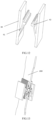
FIG. 1 illustrates a schematic diagram of a structure of a laminated terminal according to an embodiment of the present disclosure; -
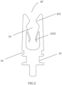
FIG. 2 illustrates a schematic diagram of a planar structure of the laminated terminal ofFIG. 1 ; -
FIG. 3 illustrates a schematic diagram of a structure of a plug-in terminal composed of the laminated terminals ofFIG. 1 ; -
FIG. 4 illustrates a schematic diagram of a structure of a laminated terminal according to another embodiment of the present disclosure; -
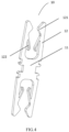
FIG. 5 illustrates a schematic diagram of a planar structure of the laminated terminal ofFIG. 4 ; -
FIG. 6 illustrates a schematic diagram of a structure of a plug-in terminal composed of the laminated terminals ofFIG. 4 and a first buckle; -
FIG. 7 illustrates a schematic diagram of a plug-in terminal composed of the laminated terminals ofFIG. 4 and a second buckle; -
FIG. 8 illustrates a schematic diagram of a structure of the laminated terminals ofFIG. 4 which are stacked together; -
FIG. 9 illustrates a schematic diagram of a structure of a first buckle; -
FIG. 10 illustrates a schematic diagram of a structure of a second buckle; -
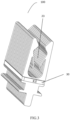
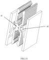
FIG. 11 illustrates a schematic diagram of a mounting structure for a plug-in terminal and a fixing sidewall; -
FIG. 12 illustrates a schematic diagram of a structure of a fixing sidewall; -
FIG. 13 illustrates a schematic diagram of a mounting structure for a terminal mounting structure and a mating terminal in a direction of 180°; -
FIG. 14 illustrates a schematic diagram of a mounting structure for a terminal mounting structure and a mating terminal in a direction of 90°; and -
FIG. 15 illustrates a plan view of a mounting structure for a terminal mounting structure and a mating terminal. -
- 100: plug-in terminal;
- 10: laminated terminal; 11: laminate base body; 12: plug-in arm; 13: plug-in space; 14: buckle recess; 15: fixing recess;
- 121: contact portion; 122: cantilever; 1221: bent portion;
- 23: plug-in groove; 24: buckle groove; 25: fixing groove;
- 30: first buckle; 301: fixing portion; 302: holding portion; 31: second buckle; 311: first fixing portion; 312: second fixing portion; 32: hollow structure;
- 40: fixing sidewall; 41: elastic piece; 42: fixing block;
- 200: mating terminal.
- The technical solutions in the embodiments of the present disclosure will be clearly and completely described below in conjunction with the drawings for the embodiments of the present disclosure. Obviously, those described are merely apart, rather than all, of the embodiments of the present disclosure. Based on the embodiments of the present disclosure, any other embodiment obtained by those of ordinary skill in the art without paying any creative effort should fall within the protection scope of the present disclosure.
- As illustrated in
FIGS. 1 to 3 , an embodiment of a first aspect of the present disclosure provides a plug-interminal 100, which includes a plurality oflaminated terminals 10 stacked in a transverse direction, each of thelaminated terminals 10 includes alaminate base body 11 and plug-inarms 12 longitudinally extending from one end of thelaminate base body 11 and disposed to be paired, such as two oppositely disposed plug-inarms 12, with a plug-inspace 13 formed between the paired plug-inarms 12; acontact portion 121 protruding toward the plug-inspace 13 and a protruding cantilever with elastic 122 are sequentially disposed from a free end of the plug-inarm 12 to thelaminate base body 11; the plug-inspaces 13 are stacked in the transverse direction to form a plug-ingroove 23, the plug-ingroove 23 is configured to interface with a mating terminal 200 (FIG. 13 ) to realize an electrical connection between the plug-interminal 100 and themating terminal 200; and the transverse direction is a stacking direction of thelaminated terminals 10 as illustrated inFIG. 3 . - The plug-in
arm 12 of each of thelaminated terminals 10 of the plug-interminal 100 is provided with thecantilever 122, which increases contact points between the plug-interminal 100 and themating terminal 200 and then increases the contact area between the plug-interminal 100 and themating terminal 200. - When the
mating terminal 200 is plugged into the plug-interminal 100, thecontact portion 121 and thecantilever 122 are in contact with themating terminal 200 and realize an electrical connection, thereby ensuring the connection reliability and the conductive effect. The plug-interminal 100 is composed of a plurality of thelaminated terminals 10, which can ensure a stable clamping structure, reduce the deformation and increase the strength of the plug-inarm 12. - In an embodiment, as illustrated in
FIGS. 4 to 7 , each of thelaminated terminals 10 further includes the plug-inarms 12 extending longitudinally from the other end of thelaminate base body 11 and disposed to be paired, such as another two oppositely disposed plug-inarms 12. By disposing the plug-inarms 12 on the two ends of thelaminate base 11 respectively, thelaminated terminal 10 can be plugged with themating terminal 200 in two opposite directions. - The
laminated terminal 10 may be formed by be punching or cutting a plate and has a sheet shape. Thelaminated terminals 10 are distributed in a stacked state in the plug-interminal 100, so that the plug-interminal 100 has a high mechanical connection performance, while ensuring the conductive connection performance between the plug-interminal 100 and themating terminal 200. The punching or cutting of the plate is simple and the process is mature, so that thelaminated terminals 10 can be quickly machined in large quantities, thereby saving the machining cost and improving the production efficiency. Themating terminal 200 cooperated with the plug-in terminal 100 may have a sheet shape or a plate shape. By adjusting the width of the plug-inarm 12 or the number of thelaminated terminals 10, the clamping force can be controlled to facilitate the match with themating terminal 200 and meet various plug-in requirements. By disposing the plug-inarms 12 of different sizes, it is possible to adapt to themating terminals 200 of different shapes. - In an embodiment, as illustrated in
FIGS. 4 and5 , thecontact portions 121 in thelaminated terminal 10 are symmetrically disposed. Therefore, when themating terminal 200 is plugged into the plug-ingroove 23, the stresses on both sides of themating terminal 200 are corresponding to each other to achieve a better clamping effect. - In an embodiment, as illustrated in
FIGS. 4 and5 , thecantilevers 122 in thelaminated terminal 10 are symmetrically disposed. Therefore, when themating terminal 200 is plugged into the plug-ingroove 23, the stresses on both sides of themating terminal 200 are corresponding to each other to achieve a better clamping effect. - In an embodiment, as illustrated in
FIGS. 1 to 7 , thecantilever 122 extends from a free end of the plug-inarm 12 toward thelaminate base body 11. A direction in which thecantilever 122 extends from the free end of the plug-inarm 12 toward thelaminate base body 11 is a direction in which themating terminal 200 is plugged into theplug groove 23. Therefore, in practical application, the failure of thecantilever 122 caused by the oblique plug-in of themating terminal 200 is avoided, thereby avoiding the poor electrical contact between the plug-interminal 100 and themating terminal 200. - In an embodiment, as illustrated in
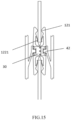
FIG. 5 , abent portion 1221 is disposed on a side at the free end of thecantilever 122, and an outer side of thebent portion 1221 faces the plug-inspace 13. - By disposing the
bent portion 1221 on thecantilever 122, the clamping force of thelaminated terminal 10 to themating terminal 200 can be increased when the plug-interminal 100 is plugged into themating terminal 200. The outer side of thebent portion 1221 is a protruding side. - In an embodiment, a minimum distance between the
bent portions 1221 on the paired plug-inarms 12 is less than or equal to a minimum distance between thecontact portions 121 on the paired plug-inarms 12. A minimum distance between two oppositebent portions 1221 in a free state is less than or equal to a minimum distance between twoopposite contact portions 121 in a free state, so that thecantilever 122 can generate a better clamping force for themating terminal 200 when themating terminal 200 is plugged into the plug-ingroove 23. - In an embodiment, as illustrated in
FIGS. 1 to 3 , one end of each of thelaminate base bodies 11 includes at least one pair of buckle recesses 14 which are oppositely disposed. As illustrated inFIG. 8 , the buckle recesses 14 of the plurality oflaminate base bodies 11 are stacked in the transverse direction to form correspondingbuckle grooves 24. As illustrated inFIG. 3 , the plug-in terminal 100 further includes at least one pair offirst buckles 30. As illustrated inFIG. 9 , thefirst buckle 30 includes a fixingportion 301 and holdingportions 302 disposed at two ends of the fixingportion 301; the fixingportions 301 of one pair of the first buckles 30 are respectively buckled in thecorresponding buckle grooves 24, and the holdingportions 302 of at least one pair of the first buckles 30 are mutually clamped to fix the plurality oflaminated terminals 10 together. - As illustrated in
FIG. 3 , one pair of the first buckles 30 may be cooperated with the plug-in terminal with one pair of thebuckle grooves 24, or as illustrated inFIG. 6 , the plug-interminal 100 includes two pairs ofbuckle grooves 24, with which two pairs offirst buckles 30 are cooperated respectively to fix the plurality oflaminated terminals 10 together. - The
first buckle 30 is made of a plastic material or any other hard material. - In an embodiment, as illustrated in
FIGS. 13 and14 , when themating terminal 200 is plugged into the plug-interminal 100, the plug-inarm 12 stretches, and a tension on thelaminate base body 11 will be transferred through thefirst buckle 30. By disposing thefirst buckle 30, the plug-inarm 12 can be supported to avoid the failure of the plug-in terminal 100 caused by excessive plug-in and unplug-in of themating terminal 200. - In an embodiment, as illustrated in
FIGS. 4 to 6 and7 , two ends of each of thelaminate base bodies 11 are respectively provided with opposite buckle recesses 14. As illustrated inFIG. 8 , two pairs the of buckle recesses 14 of the plurality oflaminate base bodies 11 are stacked in the transverse direction to form thecorresponding buckle grooves 24, a fixingrecess 15 is further disposed between the buckle recesses 14 at the two ends of each of thelaminate base bodies 11, and the fixing recesses 15 of the plurality oflaminate base bodies 11 are stacked in the transverse direction to form a fixinggroove 25. As illustrated inFIG. 10 , the plug-in terminal 100 further includes a pair ofsecond buckles 31, each of which includes a fixingportion 301 and holdingportions 302 disposed at two ends of the fixingportion 301, in which the fixingportion 301 has ahollow structure 32 that divides the fixingportion 301 into afirst fixing portion 311 and asecond fixing portion 312 which are respectively buckled in thecorresponding buckle grooves 24, and the holdingportions 302 on the same side of one pair of the second buckles 31 are clamped with each other to fix the plurality oflaminated terminals 10 together, and in which the fixinggroove 25 is exposed through thehollow structure 32. - The
second buckle 31 is made of a plastic material or any other hard material. - An embodiment of a second aspect of the present disclosure provides a plug-in terminal mounting structure, including fixing
sidewalls 40 which are oppositely disposed and a plug-interminal 100, in which inner sides of the fixingsidewall 40 are respectively provided with extendedelastic pieces 41, ends of theelastic pieces 41 are respectively provided with protruding fixing blocks 42, and the fixing blocks 42 are cooperatively connected to the fixinggroove 25. - Since the inner side of the fixing
sidewall 40 is provided with theelastic piece 41, when themating terminal 200 is plugged into the plug-interminal 100, theelastic piece 41 contracts, so that the fixinggroove 25 also contracts, thereby fixing and supporting the plug-interminal 100. The plug-interminal 100 is cooperated with the fixingblock 42 of theelastic piece 41, and is detachable during mounting due to the elastic effect of theelastic piece 41. In the directions as illustrated inFIGS. 11 and12 , the plug-interminal 100 is mounted to the fixingsidewall 40 from bottom to top, and the plug-in terminal 100 can be easily plugged between two opposite fixing sidewalls 40 due to the elastic effect of theelastic piece 41, so that the fixingblock 42 can be successfully plugged into the fixinggroove 25, thereby saving the cost of the later maintenance. As illustrated inFIGS. 13 to 15 , after the plug-interminal 100 is mounted on an insulator, it can be plugged into themating terminal 200 in the directions of 90° and 180°, and a plug-in direction is from top to bottom, thereby achieving the adaption with the high-current mating terminal 200. - Those described above are only several embodiments of the present disclosure, and those skilled in the art can make various modifications or variations to the embodiments of the present disclosure according to the application document without departing from the spirit and scope of the present disclosure. It should be understood that the orientations or positional relationships indicated by the terms "length", "width", "upper", "lower", "front", "rear", "left", "right", "vertical", "horizontal", "top", "bottom", "inner", "outer", etc. are based on those illustrated in the drawings, merely for the convenience of describing the present disclosure and simplifying the description, rather than indicating or implying that a device or element referred to must have a particular orientation or must be constructed and operated in a particular orientation, and hence cannot be construed as limitations to the present disclosure.
- In addition, the terms "first", "second", "third" and "fourth" are used for descriptive purposes only, and cannot be understood as indicating or implying relative importance or implicitly indicating the number of the technical features referred to.
- In the present disclosure, unless otherwise expressly specified and limited, a term such as "mount", "connect", "fix" or the like should be broadly understood, and for example, it may be a fixed connection, a detachable connection, an integration, a mechanical connection, an electrical connection, a direct connection, an indirect connection through an intermediate medium, or a communication between the interiors of two elements, or an interactive relationship between two elements. For those skilled in the art, the specific meanings of the above terms in the present disclosure can be understood according to specific situations.
Claims (10)
- A plug-in terminal, wherein comprising a plurality of laminated terminals stacked in a transverse direction, each of the laminated terminals comprises: a laminate base body and plug-in arms longitudinally extending from one end of the laminate base body and disposed to be paired, with a plug-in space formed between the paired plug-in arms;a contact portion protruding toward the plug-in space and a protruding cantilever with elastic are sequentially disposed from a free end of the plug-in arm to the laminate base body; anda plurality of the plug-in spaces are stacked in the transverse direction to form a plug-in groove, the plug-in groove is configured to interface with a mating terminal to realize an electrical connection between the plug-in terminal and the mating terminal.
- The plug-in terminal according to claim 1, wherein each of the laminated terminals further comprises the plug-in arms extending longitudinally from the other end of the laminate base body and disposed to be paired.
- The plug-in terminal according to claim 1, wherein the contact portions on the paired plug-in arms in the laminated terminal are symmetrically disposed.
- The plug-in terminal according to claim 1, wherein the cantilevers on the paired plug-in arms in the laminated terminal are symmetrically disposed.
- The plug-in terminal according to claim 1, wherein the cantilever extends from a free end of the plug-in arm toward the laminate base body.
- The plug-in terminal according to claim 5, wherein a bent portion is disposed on a side at the free end of the cantilever, and an outer side of the bent portion faces the plug-in space.
- The plug-in terminal according to claim 6, wherein a minimum distance between the bent portions on the paired plug-in arms is less than or equal to a minimum distance between the contact portions on the paired plug-in arms.
- The plug-in terminal according to claim 1, wherein one end of each of the laminate base bodies comprises at least one pair of buckle recesses which are oppositely disposed; the buckle recesses of the plurality of laminate base bodies are stacked in the transverse direction to form corresponding buckle groove; the plug-in terminal further comprises at least one pair of first buckles, the first buckle comprises a fixing portion and holding portions disposed at two ends of the fixing portion; the fixing portions of one pair of the first buckles are respectively buckled in the corresponding buckle grooves, and the holding portions of at least one pair of the first buckles are mutually clamped to fix the plurality of laminated terminals together.
- The plug-in terminal according to claim 1, wherein two ends of each of the laminate base bodies are respectively provided with opposite buckle recesses, a fixing recess is further disposed between the buckle recesses at the two ends of each of the laminate base bodies, and two pairs the of buckle recesses of the plurality of laminate base bodies are stacked in the transverse direction to form corresponding buckle grooves, and the fixing recesses of the plurality of laminate base bodies are stacked in the transverse direction to form a fixing groove; the plug-in terminal further comprises a pair of second buckles, each of the second buckles comprises a fixing portion and holding portions disposed at two ends of the fixing portion, and the fixing portion has a hollow structure that divides the fixing portion into a first fixing portion and a second fixing portion which are respectively buckled in the corresponding buckle grooves, and the holding portions on the same side of one pair of the second buckles are clamped with each other to fix the plurality of laminated terminals together, and the fixing groove is exposed through the hollow structure.
- A plug-in terminal mounting structure, wherein comprising fixing sidewalls which are oppositely disposed and the plug-in terminal according to any one of claims 1 to 9, inner sides of the fixing sidewalls are respectively provided with extended elastic pieces, ends of the elastic pieces are respectively provided with protruding fixing blocks, and the fixing blocks are cooperatively connected to the fixing groove.
Applications Claiming Priority (2)
| Application Number | Priority Date | Filing Date | Title |
|---|---|---|---|
| CN202123264258.7U CN217215185U (en) | 2021-12-23 | 2021-12-23 | Plug terminal and plug terminal mounting structure |
| PCT/CN2022/140902 WO2023116807A1 (en) | 2021-12-23 | 2022-12-22 | Insertion terminal and insertion terminal mounting structure |
Publications (4)
| Publication Number | Publication Date |
|---|---|
| EP4456335A1 true EP4456335A1 (en) | 2024-10-30 |
| EP4456335A4 EP4456335A4 (en) | 2025-03-19 |
| EP4456335C0 EP4456335C0 (en) | 2026-03-04 |
| EP4456335B1 EP4456335B1 (en) | 2026-03-04 |
Family
ID=82785590
Family Applications (1)
| Application Number | Title | Priority Date | Filing Date |
|---|---|---|---|
| EP22910119.1A Active EP4456335B1 (en) | 2021-12-23 | 2022-12-22 | Insertion terminal and insertion terminal mounting structure |
Country Status (5)
| Country | Link |
|---|---|
| US (1) | US20250070497A1 (en) |
| EP (1) | EP4456335B1 (en) |
| JP (1) | JP3250751U (en) |
| CN (1) | CN217215185U (en) |
| WO (1) | WO2023116807A1 (en) |
Families Citing this family (3)
| Publication number | Priority date | Publication date | Assignee | Title |
|---|---|---|---|---|
| JP7601484B2 (en) * | 2020-07-31 | 2024-12-17 | TE Connectivity Japan合同会社 | Contact Assembly |
| CN113571934A (en) * | 2021-08-17 | 2021-10-29 | 长春捷翼汽车零部件有限公司 | Plug terminal, plug structure and motor vehicle |
| CN217215185U (en) * | 2021-12-23 | 2022-08-16 | 长春捷翼汽车零部件有限公司 | Plug terminal and plug terminal mounting structure |
Family Cites Families (9)
| Publication number | Priority date | Publication date | Assignee | Title |
|---|---|---|---|---|
| JPH06111871A (en) * | 1992-09-30 | 1994-04-22 | Matsushita Electric Works Ltd | Connector |
| US5913699A (en) * | 1997-11-03 | 1999-06-22 | Molex Incorporated | Laminated spring structure and flexible circuitry connector incorporating same |
| JP5701915B2 (en) * | 2013-02-05 | 2015-04-15 | ヒロセ電機株式会社 | Electrical connector with multi-contact terminals |
| CN203312506U (en) * | 2013-05-10 | 2013-11-27 | 町洋机电(中国)有限公司 | Multi-point contact low-impedance plug-in type electric connector |
| JP6815029B2 (en) * | 2016-11-25 | 2021-01-20 | 日本圧着端子製造株式会社 | Contact, connector member, connector and connected member |
| CN110364842B (en) * | 2018-03-26 | 2021-05-28 | 泰科电子(上海)有限公司 | Conductive Terminals and Connectors |
| CN110729580B (en) * | 2019-11-20 | 2025-01-28 | 四川永贵科技有限公司 | A staggered superimposed spring fork assembly |
| CN112928512B (en) * | 2019-12-05 | 2023-01-31 | 泰科电子(上海)有限公司 | Electrical connector |
| CN217215185U (en) * | 2021-12-23 | 2022-08-16 | 长春捷翼汽车零部件有限公司 | Plug terminal and plug terminal mounting structure |
-
2021
- 2021-12-23 CN CN202123264258.7U patent/CN217215185U/en active Active
-
2022
- 2022-12-22 JP JP2024600090U patent/JP3250751U/en active Active
- 2022-12-22 WO PCT/CN2022/140902 patent/WO2023116807A1/en not_active Ceased
- 2022-12-22 EP EP22910119.1A patent/EP4456335B1/en active Active
- 2022-12-22 US US18/721,095 patent/US20250070497A1/en active Pending
Also Published As
| Publication number | Publication date |
|---|---|
| CN217215185U (en) | 2022-08-16 |
| EP4456335C0 (en) | 2026-03-04 |
| WO2023116807A1 (en) | 2023-06-29 |
| EP4456335A4 (en) | 2025-03-19 |
| JP3250751U (en) | 2025-03-27 |
| US20250070497A1 (en) | 2025-02-27 |
| EP4456335B1 (en) | 2026-03-04 |
Similar Documents
| Publication | Publication Date | Title |
|---|---|---|
| US20250070497A1 (en) | Insertion terminal and insertion terminal mounting structure | |
| CN2757364Y (en) | Electric connector | |
| CN220341535U (en) | Floating electric connector | |
| CN116544691A (en) | Terminal module and electric connector | |
| CN112072356A (en) | Two-way heap heavy current jack terminal and have its connector | |
| US6629853B2 (en) | Self-aligning power connector system | |
| CN209119379U (en) | A kind of dislocation single side elastic slice and combination dislocation single side elastic slice | |
| CN115603085A (en) | Piece type contact piece jack structure | |
| CN213692499U (en) | A small volume and high current electrical connection shrapnel | |
| CN221305041U (en) | Contact and connector | |
| CN201805027U (en) | a battery connector | |
| CN215527891U (en) | Battery switching structure, connection piece, connection structure and battery module | |
| CN216289234U (en) | Connector with a locking member | |
| CN211530249U (en) | Female terminal electric connector | |
| CN113346197A (en) | Battery switching structure, connection piece, connection structure and battery module | |
| EP4583319A1 (en) | Chip-type contact element and connector using chip-type contact element | |
| CN212750734U (en) | Conductive rod, connecting seat and contactor applied to contactor | |
| US20230369816A1 (en) | Connector and Connector Assembly | |
| CN219534904U (en) | Connector | |
| CN223260975U (en) | Conductive terminal, battery breaking device, battery pack and electricity utilization device | |
| CN219163720U (en) | Novel main line electric terminal | |
| CN2399842Y (en) | Eelctrical connector | |
| CN222282309U (en) | Socket and power adapter | |
| CN222735489U (en) | Connector and electrical device | |
| CN217848364U (en) | Connector for electronic equipment |
Legal Events
| Date | Code | Title | Description |
|---|---|---|---|
| STAA | Information on the status of an ep patent application or granted ep patent |
Free format text: STATUS: THE INTERNATIONAL PUBLICATION HAS BEEN MADE |
|
| PUAI | Public reference made under article 153(3) epc to a published international application that has entered the european phase |
Free format text: ORIGINAL CODE: 0009012 |
|
| STAA | Information on the status of an ep patent application or granted ep patent |
Free format text: STATUS: REQUEST FOR EXAMINATION WAS MADE |
|
| 17P | Request for examination filed |
Effective date: 20240708 |
|
| AK | Designated contracting states |
Kind code of ref document: A1 Designated state(s): AL AT BE BG CH CY CZ DE DK EE ES FI FR GB GR HR HU IE IS IT LI LT LU LV MC ME MK MT NL NO PL PT RO RS SE SI SK SM TR |
|
| P01 | Opt-out of the competence of the unified patent court (upc) registered |
Free format text: CASE NUMBER: APP_62556/2024 Effective date: 20241123 |
|
| A4 | Supplementary search report drawn up and despatched |
Effective date: 20250219 |
|
| RIC1 | Information provided on ipc code assigned before grant |
Ipc: H01R 13/422 20060101ALN20250213BHEP Ipc: H01R 13/24 20060101ALI20250213BHEP Ipc: H01R 31/06 20060101ALI20250213BHEP Ipc: H01R 13/20 20060101ALI20250213BHEP Ipc: H01R 13/40 20060101ALI20250213BHEP Ipc: H01R 13/11 20060101AFI20250213BHEP |
|
| DAV | Request for validation of the european patent (deleted) | ||
| DAX | Request for extension of the european patent (deleted) | ||
| GRAP | Despatch of communication of intention to grant a patent |
Free format text: ORIGINAL CODE: EPIDOSNIGR1 |
|
| STAA | Information on the status of an ep patent application or granted ep patent |
Free format text: STATUS: GRANT OF PATENT IS INTENDED |
|
| RIC1 | Information provided on ipc code assigned before grant |
Ipc: H01R 13/11 20060101AFI20251014BHEP Ipc: H01R 13/40 20060101ALI20251014BHEP Ipc: H01R 13/20 20060101ALI20251014BHEP Ipc: H01R 31/06 20060101ALI20251014BHEP Ipc: H01R 13/24 20060101ALI20251014BHEP Ipc: H01R 13/422 20060101ALN20251014BHEP |
|
| INTG | Intention to grant announced |
Effective date: 20251028 |
|
| RIC1 | Information provided on ipc code assigned before grant |
Ipc: H01R 13/11 20060101AFI20251020BHEP Ipc: H01R 13/40 20060101ALI20251020BHEP Ipc: H01R 13/20 20060101ALI20251020BHEP Ipc: H01R 31/06 20060101ALI20251020BHEP Ipc: H01R 13/24 20060101ALI20251020BHEP Ipc: H01R 13/422 20060101ALN20251020BHEP |
|
| GRAS | Grant fee paid |
Free format text: ORIGINAL CODE: EPIDOSNIGR3 |
|
| GRAA | (expected) grant |
Free format text: ORIGINAL CODE: 0009210 |
|
| STAA | Information on the status of an ep patent application or granted ep patent |
Free format text: STATUS: THE PATENT HAS BEEN GRANTED |
|
| AK | Designated contracting states |
Kind code of ref document: B1 Designated state(s): AL AT BE BG CH CY CZ DE DK EE ES FI FR GB GR HR HU IE IS IT LI LT LU LV MC ME MK MT NL NO PL PT RO RS SE SI SK SM TR |
|
| REG | Reference to a national code |
Ref country code: CH Ref legal event code: F10 Free format text: ST27 STATUS EVENT CODE: U-0-0-F10-F00 (AS PROVIDED BY THE NATIONAL OFFICE) Effective date: 20260304 Ref country code: GB Ref legal event code: FG4D |
|
| REG | Reference to a national code |
Ref country code: DE Ref legal event code: R096 Ref document number: 602022031900 Country of ref document: DE |
|
| REG | Reference to a national code |
Ref country code: IE Ref legal event code: FG4D |
|
| U01 | Request for unitary effect filed |
Effective date: 20260319 |
|
| P04 | Withdrawal of opt-out of the competence of the unified patent court (upc) registered |
Free format text: CASE NUMBER: APP_62556_1/2024 Effective date: 20260324 |
|
| U07 | Unitary effect registered |
Designated state(s): AT BE BG DE DK EE FI FR IT LT LU LV MT NL PT RO SE SI Effective date: 20260324 |