EP4456333A1 - Connector - Google Patents
Connector Download PDFInfo
- Publication number
- EP4456333A1 EP4456333A1 EP24164122.4A EP24164122A EP4456333A1 EP 4456333 A1 EP4456333 A1 EP 4456333A1 EP 24164122 A EP24164122 A EP 24164122A EP 4456333 A1 EP4456333 A1 EP 4456333A1
- Authority
- EP
- European Patent Office
- Prior art keywords
- connector terminal
- balls
- connection surface
- retention member
- ball
- Prior art date
- Legal status (The legal status is an assumption and is not a legal conclusion. Google has not performed a legal analysis and makes no representation as to the accuracy of the status listed.)
- Granted
Links
Images

Classifications
-
- H—ELECTRICITY
- H01—ELECTRIC ELEMENTS
- H01R—ELECTRICALLY-CONDUCTIVE CONNECTIONS; STRUCTURAL ASSOCIATIONS OF A PLURALITY OF MUTUALLY-INSULATED ELECTRICAL CONNECTING ELEMENTS; COUPLING DEVICES; CURRENT COLLECTORS
- H01R13/00—Details of coupling devices of the kinds covered by groups H01R12/70 or H01R24/00 - H01R33/00
- H01R13/02—Contact members
- H01R13/20—Pins, blades, or sockets shaped, or provided with separate member, to retain co-operating parts together
-
- H—ELECTRICITY
- H01—ELECTRIC ELEMENTS
- H01R—ELECTRICALLY-CONDUCTIVE CONNECTIONS; STRUCTURAL ASSOCIATIONS OF A PLURALITY OF MUTUALLY-INSULATED ELECTRICAL CONNECTING ELEMENTS; COUPLING DEVICES; CURRENT COLLECTORS
- H01R13/00—Details of coupling devices of the kinds covered by groups H01R12/70 or H01R24/00 - H01R33/00
- H01R13/62—Means for facilitating engagement or disengagement of coupling parts or for holding them in engagement
-
- H—ELECTRICITY
- H01—ELECTRIC ELEMENTS
- H01R—ELECTRICALLY-CONDUCTIVE CONNECTIONS; STRUCTURAL ASSOCIATIONS OF A PLURALITY OF MUTUALLY-INSULATED ELECTRICAL CONNECTING ELEMENTS; COUPLING DEVICES; CURRENT COLLECTORS
- H01R13/00—Details of coupling devices of the kinds covered by groups H01R12/70 or H01R24/00 - H01R33/00
- H01R13/02—Contact members
- H01R13/10—Sockets for co-operation with pins or blades
- H01R13/14—Resiliently-mounted rigid sockets
-
- H—ELECTRICITY
- H01—ELECTRIC ELEMENTS
- H01R—ELECTRICALLY-CONDUCTIVE CONNECTIONS; STRUCTURAL ASSOCIATIONS OF A PLURALITY OF MUTUALLY-INSULATED ELECTRICAL CONNECTING ELEMENTS; COUPLING DEVICES; CURRENT COLLECTORS
- H01R13/00—Details of coupling devices of the kinds covered by groups H01R12/70 or H01R24/00 - H01R33/00
- H01R13/02—Contact members
- H01R13/10—Sockets for co-operation with pins or blades
-
- H—ELECTRICITY
- H01—ELECTRIC ELEMENTS
- H01R—ELECTRICALLY-CONDUCTIVE CONNECTIONS; STRUCTURAL ASSOCIATIONS OF A PLURALITY OF MUTUALLY-INSULATED ELECTRICAL CONNECTING ELEMENTS; COUPLING DEVICES; CURRENT COLLECTORS
- H01R13/00—Details of coupling devices of the kinds covered by groups H01R12/70 or H01R24/00 - H01R33/00
- H01R13/02—Contact members
- H01R13/10—Sockets for co-operation with pins or blades
- H01R13/11—Resilient sockets
- H01R13/111—Resilient sockets co-operating with pins having a circular transverse section
-
- H—ELECTRICITY
- H01—ELECTRIC ELEMENTS
- H01R—ELECTRICALLY-CONDUCTIVE CONNECTIONS; STRUCTURAL ASSOCIATIONS OF A PLURALITY OF MUTUALLY-INSULATED ELECTRICAL CONNECTING ELEMENTS; COUPLING DEVICES; CURRENT COLLECTORS
- H01R13/00—Details of coupling devices of the kinds covered by groups H01R12/70 or H01R24/00 - H01R33/00
- H01R13/02—Contact members
- H01R13/15—Pins, blades or sockets having separate spring member for producing or increasing contact pressure
- H01R13/18—Pins, blades or sockets having separate spring member for producing or increasing contact pressure with the spring member surrounding the socket
-
- H—ELECTRICITY
- H01—ELECTRIC ELEMENTS
- H01R—ELECTRICALLY-CONDUCTIVE CONNECTIONS; STRUCTURAL ASSOCIATIONS OF A PLURALITY OF MUTUALLY-INSULATED ELECTRICAL CONNECTING ELEMENTS; COUPLING DEVICES; CURRENT COLLECTORS
- H01R13/00—Details of coupling devices of the kinds covered by groups H01R12/70 or H01R24/00 - H01R33/00
- H01R13/02—Contact members
- H01R13/15—Pins, blades or sockets having separate spring member for producing or increasing contact pressure
- H01R13/187—Pins, blades or sockets having separate spring member for producing or increasing contact pressure with spring member in the socket
-
- H—ELECTRICITY
- H01—ELECTRIC ELEMENTS
- H01R—ELECTRICALLY-CONDUCTIVE CONNECTIONS; STRUCTURAL ASSOCIATIONS OF A PLURALITY OF MUTUALLY-INSULATED ELECTRICAL CONNECTING ELEMENTS; COUPLING DEVICES; CURRENT COLLECTORS
- H01R13/00—Details of coupling devices of the kinds covered by groups H01R12/70 or H01R24/00 - H01R33/00
- H01R13/02—Contact members
- H01R13/22—Contacts for co-operating by abutting
- H01R13/24—Contacts for co-operating by abutting resilient; resiliently-mounted
- H01R13/2407—Contacts for co-operating by abutting resilient; resiliently-mounted characterized by the resilient means
-
- H—ELECTRICITY
- H01—ELECTRIC ELEMENTS
- H01R—ELECTRICALLY-CONDUCTIVE CONNECTIONS; STRUCTURAL ASSOCIATIONS OF A PLURALITY OF MUTUALLY-INSULATED ELECTRICAL CONNECTING ELEMENTS; COUPLING DEVICES; CURRENT COLLECTORS
- H01R13/00—Details of coupling devices of the kinds covered by groups H01R12/70 or H01R24/00 - H01R33/00
- H01R13/02—Contact members
- H01R13/22—Contacts for co-operating by abutting
- H01R13/24—Contacts for co-operating by abutting resilient; resiliently-mounted
- H01R13/2407—Contacts for co-operating by abutting resilient; resiliently-mounted characterized by the resilient means
- H01R13/2421—Contacts for co-operating by abutting resilient; resiliently-mounted characterized by the resilient means using coil springs
-
- H—ELECTRICITY
- H01—ELECTRIC ELEMENTS
- H01R—ELECTRICALLY-CONDUCTIVE CONNECTIONS; STRUCTURAL ASSOCIATIONS OF A PLURALITY OF MUTUALLY-INSULATED ELECTRICAL CONNECTING ELEMENTS; COUPLING DEVICES; CURRENT COLLECTORS
- H01R13/00—Details of coupling devices of the kinds covered by groups H01R12/70 or H01R24/00 - H01R33/00
- H01R13/02—Contact members
- H01R13/22—Contacts for co-operating by abutting
- H01R13/24—Contacts for co-operating by abutting resilient; resiliently-mounted
- H01R13/2464—Contacts for co-operating by abutting resilient; resiliently-mounted characterized by the contact point
- H01R13/2478—Contacts for co-operating by abutting resilient; resiliently-mounted characterized by the contact point spherical
-
- H—ELECTRICITY
- H01—ELECTRIC ELEMENTS
- H01R—ELECTRICALLY-CONDUCTIVE CONNECTIONS; STRUCTURAL ASSOCIATIONS OF A PLURALITY OF MUTUALLY-INSULATED ELECTRICAL CONNECTING ELEMENTS; COUPLING DEVICES; CURRENT COLLECTORS
- H01R13/00—Details of coupling devices of the kinds covered by groups H01R12/70 or H01R24/00 - H01R33/00
- H01R13/40—Securing contact members in or to a base or case; Insulating of contact members
- H01R13/405—Securing in non-demountable manner, e.g. moulding, riveting
-
- H—ELECTRICITY
- H01—ELECTRIC ELEMENTS
- H01R—ELECTRICALLY-CONDUCTIVE CONNECTIONS; STRUCTURAL ASSOCIATIONS OF A PLURALITY OF MUTUALLY-INSULATED ELECTRICAL CONNECTING ELEMENTS; COUPLING DEVICES; CURRENT COLLECTORS
- H01R13/00—Details of coupling devices of the kinds covered by groups H01R12/70 or H01R24/00 - H01R33/00
- H01R13/46—Bases; Cases
- H01R13/502—Bases; Cases composed of different pieces
- H01R13/5025—Bases; Cases composed of different pieces one or more pieces being of resilient material
-
- H—ELECTRICITY
- H01—ELECTRIC ELEMENTS
- H01R—ELECTRICALLY-CONDUCTIVE CONNECTIONS; STRUCTURAL ASSOCIATIONS OF A PLURALITY OF MUTUALLY-INSULATED ELECTRICAL CONNECTING ELEMENTS; COUPLING DEVICES; CURRENT COLLECTORS
- H01R24/00—Two-part coupling devices, or either of their cooperating parts, characterised by their overall structure
- H01R24/005—Two-part coupling devices, or either of their cooperating parts, characterised by their overall structure requiring successive relative motions to complete the coupling, e.g. bayonet type
-
- H—ELECTRICITY
- H01—ELECTRIC ELEMENTS
- H01R—ELECTRICALLY-CONDUCTIVE CONNECTIONS; STRUCTURAL ASSOCIATIONS OF A PLURALITY OF MUTUALLY-INSULATED ELECTRICAL CONNECTING ELEMENTS; COUPLING DEVICES; CURRENT COLLECTORS
- H01R4/00—Electrically-conductive connections between two or more conductive members in direct contact, i.e. touching one another; Means for effecting or maintaining such contact; Electrically-conductive connections having two or more spaced connecting locations for conductors and using contact members penetrating insulation
- H01R4/28—Clamped connections, spring connections
- H01R4/50—Clamped connections, spring connections utilising a cam, wedge, cone or ball also combined with a screw
- H01R4/5058—Clamped connections, spring connections utilising a cam, wedge, cone or ball also combined with a screw using a ball
-
- H—ELECTRICITY
- H01—ELECTRIC ELEMENTS
- H01R—ELECTRICALLY-CONDUCTIVE CONNECTIONS; STRUCTURAL ASSOCIATIONS OF A PLURALITY OF MUTUALLY-INSULATED ELECTRICAL CONNECTING ELEMENTS; COUPLING DEVICES; CURRENT COLLECTORS
- H01R13/00—Details of coupling devices of the kinds covered by groups H01R12/70 or H01R24/00 - H01R33/00
- H01R13/02—Contact members
- H01R13/10—Sockets for co-operation with pins or blades
- H01R13/11—Resilient sockets
- H01R13/113—Resilient sockets co-operating with pins or blades having a rectangular transverse section
-
- H—ELECTRICITY
- H01—ELECTRIC ELEMENTS
- H01R—ELECTRICALLY-CONDUCTIVE CONNECTIONS; STRUCTURAL ASSOCIATIONS OF A PLURALITY OF MUTUALLY-INSULATED ELECTRICAL CONNECTING ELEMENTS; COUPLING DEVICES; CURRENT COLLECTORS
- H01R13/00—Details of coupling devices of the kinds covered by groups H01R12/70 or H01R24/00 - H01R33/00
- H01R13/02—Contact members
- H01R13/22—Contacts for co-operating by abutting
- H01R13/24—Contacts for co-operating by abutting resilient; resiliently-mounted
-
- H—ELECTRICITY
- H01—ELECTRIC ELEMENTS
- H01R—ELECTRICALLY-CONDUCTIVE CONNECTIONS; STRUCTURAL ASSOCIATIONS OF A PLURALITY OF MUTUALLY-INSULATED ELECTRICAL CONNECTING ELEMENTS; COUPLING DEVICES; CURRENT COLLECTORS
- H01R13/00—Details of coupling devices of the kinds covered by groups H01R12/70 or H01R24/00 - H01R33/00
- H01R13/02—Contact members
- H01R13/22—Contacts for co-operating by abutting
- H01R13/24—Contacts for co-operating by abutting resilient; resiliently-mounted
- H01R13/2407—Contacts for co-operating by abutting resilient; resiliently-mounted characterized by the resilient means
- H01R13/2428—Contacts for co-operating by abutting resilient; resiliently-mounted characterized by the resilient means using meander springs
-
- H—ELECTRICITY
- H01—ELECTRIC ELEMENTS
- H01R—ELECTRICALLY-CONDUCTIVE CONNECTIONS; STRUCTURAL ASSOCIATIONS OF A PLURALITY OF MUTUALLY-INSULATED ELECTRICAL CONNECTING ELEMENTS; COUPLING DEVICES; CURRENT COLLECTORS
- H01R13/00—Details of coupling devices of the kinds covered by groups H01R12/70 or H01R24/00 - H01R33/00
- H01R13/02—Contact members
- H01R13/22—Contacts for co-operating by abutting
- H01R13/24—Contacts for co-operating by abutting resilient; resiliently-mounted
- H01R13/2464—Contacts for co-operating by abutting resilient; resiliently-mounted characterized by the contact point
- H01R13/2485—Contacts for co-operating by abutting resilient; resiliently-mounted characterized by the contact point for contacting a ball
-
- H—ELECTRICITY
- H01—ELECTRIC ELEMENTS
- H01R—ELECTRICALLY-CONDUCTIVE CONNECTIONS; STRUCTURAL ASSOCIATIONS OF A PLURALITY OF MUTUALLY-INSULATED ELECTRICAL CONNECTING ELEMENTS; COUPLING DEVICES; CURRENT COLLECTORS
- H01R13/00—Details of coupling devices of the kinds covered by groups H01R12/70 or H01R24/00 - H01R33/00
- H01R13/40—Securing contact members in or to a base or case; Insulating of contact members
-
- H—ELECTRICITY
- H01—ELECTRIC ELEMENTS
- H01R—ELECTRICALLY-CONDUCTIVE CONNECTIONS; STRUCTURAL ASSOCIATIONS OF A PLURALITY OF MUTUALLY-INSULATED ELECTRICAL CONNECTING ELEMENTS; COUPLING DEVICES; CURRENT COLLECTORS
- H01R13/00—Details of coupling devices of the kinds covered by groups H01R12/70 or H01R24/00 - H01R33/00
- H01R13/46—Bases; Cases
-
- H—ELECTRICITY
- H01—ELECTRIC ELEMENTS
- H01R—ELECTRICALLY-CONDUCTIVE CONNECTIONS; STRUCTURAL ASSOCIATIONS OF A PLURALITY OF MUTUALLY-INSULATED ELECTRICAL CONNECTING ELEMENTS; COUPLING DEVICES; CURRENT COLLECTORS
- H01R13/00—Details of coupling devices of the kinds covered by groups H01R12/70 or H01R24/00 - H01R33/00
- H01R13/46—Bases; Cases
- H01R13/502—Bases; Cases composed of different pieces
-
- H—ELECTRICITY
- H01—ELECTRIC ELEMENTS
- H01R—ELECTRICALLY-CONDUCTIVE CONNECTIONS; STRUCTURAL ASSOCIATIONS OF A PLURALITY OF MUTUALLY-INSULATED ELECTRICAL CONNECTING ELEMENTS; COUPLING DEVICES; CURRENT COLLECTORS
- H01R13/00—Details of coupling devices of the kinds covered by groups H01R12/70 or H01R24/00 - H01R33/00
- H01R13/46—Bases; Cases
- H01R13/502—Bases; Cases composed of different pieces
- H01R13/508—Bases; Cases composed of different pieces assembled by a separate clip or spring
Definitions
- the present invention relates to a connector, particularly to a connector having a counter connector terminal housing portion in which a part of a counter connector terminal is inserted.
- a connector having a metal ball serving as a contact that is movably disposed between a connector terminal and a counter connector terminal for the purpose of reducing the sliding resistance of the counter connector terminal inserted into and pulled out from the connector terminal.
- the connector terminal is electrically connected to the counter connector terminal via the metal ball.
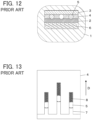
- JP 2019-67499 A discloses a connector in which a connector terminal 2 is electrically connected to a counter connector terminal 3 in a connector housing 1 made of a resin material, as shown in FIG. 12 .
- Three metal balls 5 held by a contact holder 4 and a diagonally wound coil spring 6 are disposed in the connector housing 1, and the connector terminal 2 is pressed against the three metal balls 5 by the diagonally wound coil spring 6 and thereby electrically connected to the counter connector terminal 3 via the three metal balls 5.
- the three metal balls 5 are housed together with compression coil springs 8 separately in three contact housing portions 7 formed in the contact holder 4 as shown in FIG. 13 .
- the three metal balls 5 rotate and move in accordance with movement of the counter connector terminal 3 while elastically compressing the corresponding compression coil springs 8. This structure reduces the sliding resistance during insertion of the counter connector terminal 3.
- the three contact housing portions 7 formed in the contact holder 4 extend in parallel along an insertion direction D of the counter connector terminal 3 as shown in FIG. 13 .
- the three metal balls 5 cannot move in a direction perpendicular to the insertion direction D of the counter connector terminal 3 while being able to rotate and move along the insertion direction D.
- the present invention has been made to overcome the conventional problem as above and aims at providing a connector that can establish electrical connection between a connector terminal and a counter connector terminal with high reliability no matter which direction the counter connector terminal moves relative to the connector terminal.
- a connector according to the present invention is one having a counter connector terminal housing portion in which part of a counter connector terminal is inserted, the connector comprising:
- FIG. 1 shows a connector 11 according to the embodiment and a counter connector terminal 21 to be inserted into the connector 11.
- the connector 11 includes a connector terminal 12 to be electrically connected to the counter connector terminal 21, and a shell 13 illustrated by broken lines is attached to the connector terminal 12.
- the counter connector terminal 21 is formed of a plug contact having a flat plate shape.
- the connector terminal 12 is formed of a socket contact having a flat plate shape as with the counter connector terminal 21, and has a flat connection surface 12A.
- connection surface 12A of the connector terminal 12 is defined as extending along an XY plane, the direction in which the counter connector terminal 21 is inserted with respect to the connector 11 is defined as a +Y direction, and the direction perpendicular to the connection surface 12A of the connector terminal 12 is defined as a Z direction.
- a ball assembly BA used for electrically connecting the connector terminal 12 and the counter connector terminal 21 together is mounted on the connection surface 12A of the connector terminal 12.
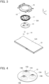
- the ball assembly BA includes three balls 14 that relay electrical connection between the connector terminal 12 and the counter connector terminal 21, a ball retention member 15 that rotatably retains the three balls 14, and a ball guide portion 16 that movably retains the ball retention member 15 along the connection surface 12A.
- FIG. 3 shows an assembly view of the ball assembly BA.
- the three balls 14 are disposed on the +Z direction side of the connection surface 12A of the connector terminal 12, the ball retention member 15 is disposed on the +Z direction side of the three balls 14, and a spring member 17 and a cover member 18 that constitute the ball guide portion 16 are sequentially disposed on the +Z direction side of the ball retention member 15.
- the three balls 14 are arranged such that all the balls 14 are not aligned in a straight line in an XY plane. In other words, in one example of the embodiment, the three balls 14 are arranged such that the shape formed by connecting the centers of the balls 14 is a triangle in an XY plane.
- the three balls 14 have a spherical shape having the same diameter and are made of, for instance, electrically conductive metal. It is sufficient for the balls 14 that at least their surfaces are electrically conductive, and for instance, use may be made of balls in each of which an electrically conductive metal layer is formed on a surface of a spherical member made of a nonconductor.
- the ball retention member 15 is formed of a plate member made of metal or another material, and includes a base portion 15A of disc shape extending along an XY plane and three projection portions 15B projecting in the +Z direction from a surface of the base portion 15A.
- the three projection portions 15B are arranged at positions of the three vertices of an equilateral triangle whose center corresponds to the center of the base portion 15A of disc shape.
- Each projection portion 15B has a cone surface 15C tapering toward the +Z direction and is provided with a circular opening 15D at its +Z directional end.
- the ball retention member 15 as above is fabricated by, for example, shearing and drawing a flat metal plate, and the three balls 14 can be housed in three recess portions formed on the -Z direction side of the three projection portions 15B.
- the spring member 17 is a plate-like member made of metal or another material, and includes a base portion 17A of equilateral triangular shape extending along an XY plane, three frame portions 17B of arc shape separately joined to the base portion 17A, and three return springs 17C extending separately from the three frame portions 17B.
- the spring member 17 is fabricated by, for example, shearing a flat metal plate.
- the three frame portions 17B of arc shape are disposed at positions of the three vertices of the base portion 17A of equilateral triangular shape, and each frame portion 17B in combination with an arc edge portion of the base portion 17A forms a circular opening portion 17D.
- the spring member 17 is configured to be fitted to the ball retention member 15 by inserting the three projection portions 15B of the ball retention member 15 into the three opening portions 17D formed by the three frame portions 17B, and the base portion 17A and the three frame portions 17B constitute a fitting portion 17E that is fitted to the ball retention member 15.
- the three return springs 17C are formed of band members having the same shape, have a spiral shape extending around the outside of the base portion 17A and the three frame portions 17B, and are elastically deformable in an XY plane.
- Each return spring 17C includes a first end portion T1 joined to the corresponding frame portion 17B of the fitting portion 17E and a second end portion T2 that is a free end.
- the second end portion T2 is provided with a bent portion 17F bent toward the +Z direction.
- the return springs 17C each have a spiral shape, a longer spring length can be ensured while an installation space for the spring member 17 is minimized, and a spring constant can be easily adjusted.
- the ball retention member 15 is disposed such that the surface, on the -Z direction side, of the base portion 15A makes contact with the connection surface 12A of the connector terminal 12 with the balls 14 being housed in ball housing portions 15E of recess shape formed on the -Z direction side of the respective projection portions 15B, as shown in FIG. 6 .
- each projection portion 15B of the ball retention member 15 is situated higher than the height corresponding to the radius of the ball 14 and lower than the height corresponding to the diameter of the ball 14 in the +Z direction from the connection surface 12A of the connector terminal 12, and has a smaller diameter than that of the ball 14. Owing to this configuration, the ball 14 housed in the ball housing portion 15E can rotate within the ball housing portion 15E without coming out of the ball housing portion 15E.
- the projection portion 15B of the ball retention member 15 has the opening 15D as above, the -Z directional end of the ball 14 housed in the ball housing portion 15E surrounded by the connection surface 12A of the connector terminal 12 and the projection portion 15B makes contact with the connection surface 12A, while the +Z directional end of the ball 14 protrudes from the opening 15D in the +Z direction, as shown in FIG. 6 .
- the spring member 17 is disposed on the ball retention member 15, and the three opening portions 17D formed by the three frame portions 17B make contact separately with the cone surfaces 15C of the three projection portions 15B of the ball retention member 15, whereby the fitting portion 17E of the spring member 17 is fitted to the ball retention member 15.
- the fitting portion 17E of the spring member 17, the ball retention member 15, and the three balls 14 are configured to be integrally movable in a two-dimensional manner along the connection surface 12A of the connector terminal 12.
- the cover member 18 is formed of a plate member made of, for example, metal and includes a cover body 18A in a frame shape extending along an XY plane, a pair of fixing portions 18B joined to the opposite ends, in the X direction, of the cover body 18A, and a pair of counter connector terminal guide portions 18C joined to the pair of fixing portions 18B.
- the cover body 18A has the shape of a ring having in its center a circular opening portion 18D.
- a circular outer peripheral portion of the cover body 18A extends along an XY plane, while an inner peripheral portion of the cover body 18A adjacent to the opening portion 18D extends along an XY plane at a height situated on the +Z direction side of the outer peripheral portion.
- the cover body 18A has such a shape as to bulge in the +Z direction from the outer peripheral portion toward the inner peripheral portion as a whole.
- the thickness of the cover body 18A in the Z direction has a smaller dimension than the diameter of the ball 14.
- the ring-shaped cover body 18A is provided with insertion holes 18E penetrating the cover body 18A in the Z direction at rotational positions spaced at 120-degree intervals about the central axis of the cover body 18A extending in the Z direction.
- the pair of fixing portions 18B are used to fix the cover member 18 to the connection surface 12A of the connector terminal 12 and extend in the X direction along an XY plane separately from the +X directional end and the -X directional end of the cover body 18A.
- the pair of counter connector terminal guide portions 18C joined to the pair of fixing portions 18B are used to guide the counter connector terminal 21 when the counter connector terminal 21 is inserted into the connector 11 as shown in FIG. 1 .
- Each counter connector terminal guide portion 18C extends in the +Y direction and the -Y direction from the corresponding fixing portion 18B and is formed of a pair of arm portions 18F that are curved in the Z direction.
- the cover member 18 is disposed on the connection surface 12A of the connector terminal 12 to cover the spring member 17 that is fitted to the ball retention member 15 by the fitting portion 17E.
- the cover member 18 is illustrated by dashed lines to show portions covered with the cover member 18.
- the three return springs 17C of the spring member 17 have a spiral shape extending along the outer peripheral portion of the ball retention member 15 on the connection surface 12A of the connector terminal 12 and are situated on the -Z direction side of the cover body 18A of the cover member 18, and the +Z directional ends of the three balls 14 retained in the ball retention member 15 are exposed through the opening portion 18D of the cover member 18.
- the thickness of the cover body 18A in the Z direction has a smaller dimension than the diameter of the ball 14, the +Z directional ends of the three balls 14 protrude in the +Z direction from the cover member 18.
- each return spring 17C of the spring member 17 is inserted in the corresponding insertion hole 18E of the cover body 18A of the cover member 18. Owing to this configuration, the positions of the second end portions T2 of the three return springs 17C are restricted.
- connection surface 12A being a horizontal surface and no external force other than gravity acts on the spring member 17, the ball retention member 15, and the three balls 14, as shown in FIG. 8
- the three return springs 17C of the spring member 17 lie in a rotationally symmetrical arrangement along the connection surface 12A, and the ball retention member 15 is in an initial position P1 in which the center of the base portion 15A of disc shape substantially coincides with the center of the circular opening portion 18D of the cover member 18.
- the insertion hole 18E of the cover body 18A of the cover member 18 is formed to be larger than the bent portion 17F at the second end portion T2 of the return spring 17C as shown in FIG. 9 such that the bent portion 17F is inserted in the insertion hole 18E with an extra margin.
- the shell 13 is formed of a plate member such as a bent metal plate as shown in FIG. 10 and includes a bottom plate portion 13A situated on the -Z direction side and extending along an XY plane, a top plate portion 13B situated on the +Z direction side and extending along an XY plane, a front plate portion 13C situated on the -Y direction side and extending along an XZ plane, and a rear plate portion 13D situated on the +Y direction side and extending along an XZ plane.
- a plate member such as a bent metal plate as shown in FIG. 10 and includes a bottom plate portion 13A situated on the -Z direction side and extending along an XY plane, a top plate portion 13B situated on the +Z direction side and extending along an XY plane, a front plate portion 13C situated on the -Y direction side and extending along an XZ plane, and a rear plate portion 13D situated on the +Y direction side and extending along an XZ plane.
- the front plate portion 13C and the rear plate portion 13D are respectively provided with opening portions 13E and 13F into which the counter connector terminal 21 is to be inserted.
- a terminal spring 13G extending while being bent in the -Z direction and the +Y direction is formed at the -Y directional end of the top plate portion 13B.
- the height of the top plate portion 13B with respect to the bottom plate portion 13A in the Z direction has a larger dimension than the sum of the thickness of the connector terminal 12 in the Z direction, the thickness of the counter connector terminal 21 in the Z direction, and the diameter of the ball 14.
- the shell 13 is attached to the connector terminal 12 such that the connector terminal 12 is situated inside the shell 13 to be in contact with the bottom plate portion 13A of the shell 13, and a counter connector terminal housing portion 13H to which the counter connector terminal 21 is to be inserted is formed between the terminal spring 13G and the connection surface 12A of the connector terminal 12.
- the ball retention member 15 When the connector 11 is assembled, first, the ball retention member 15 is disposed on the connection surface 12A of the connector terminal 12 while the balls 14 are separately housed in the three ball housing portions 15E of the ball retention member 15 as shown in FIG. 6 . At this time, the base portion 15A of the ball retention member 15 makes contact with the connection surface 12A of the connector terminal 12.
- the spring member 17 is disposed on the ball retention member 15 such that the three opening portions 17D of the spring member 17 make contact with the cone surfaces 15C of the corresponding projection portions 15B of the ball retention member 15, and the fitting portion 17E of the spring member 17 is fitted to the ball retention member 15.
- cover member 18 is put over the ball retention member 15 and the spring member 17 as shown in FIG. 8 , and the bent portions 17F of the three return springs 17C of the spring member 17 are inserted into the corresponding insertion holes 18E of the cover body 18A of the cover member 18 as shown in FIG. 9 .
- the pair of fixing portions 18B of the cover member 18 are, in plural positions, welded to the connection surface 12A of the connector terminal 12 by laser welding or another method, whereby the cover member 18 is fixed to the connector terminal 12. Consequently, the fitting portion 17E of the spring member 17, the ball retention member 15, and the three balls 14 are integrally movable along the connection surface 12A of the connector terminal 12 within the cover member 18, and the +Z directional ends of the three balls 14 retained in the ball retention member 15 are exposed through the opening portion 18D of the cover member 18.
- the shell 13 is attached to the connector terminal 12 such that the surface, on the -Z directional side, of the connector terminal 12 makes contact with the bottom plate portion 13A of the shell 13.
- the assembling operation of the connector 11 is completed.
- the insertion hole 18E of the cover member 18 is formed to be larger than the bent portion 17F of the return spring 17C as shown in FIG. 9 , the bent portion 17F can be inserted into the insertion hole 18E with an extra margin, which facilitates the assembling operation of the connector 11.
- the counter connector terminal 21 shown in FIG. 1 is moved from the -Y direction toward the +Y direction and inserted into the shell 13 of the connector 11.
- the counter connector terminal 21 is inserted into the shell 13 while being guided by the pair of counter connector terminal guide portions 18C of the cover member 18 shown in FIG. 7 to be parallel to the connection surface 12A of the connector terminal 12, and a +Y directional end portion of the counter connector terminal 21 is inserted into the counter connector terminal housing portion 13H formed between the terminal spring 13G of the shell 13 shown in FIG. 10 and the connection surface 12A of the connector terminal 12 while elastically compressing the terminal spring 13G toward the +Z direction, and is thereby pressed by the terminal spring 13G against the connection surface 12A of the connector terminal 12 in the -Z direction.
- the surface of the counter connector terminal 21 on the -Z direction side makes contact at a predetermined contact pressure with the +Z directional ends of the three balls 14 protruding from the cover member 18 in the +Z direction, the three balls 14 being retained in the ball retention member 15, and this allows the -Z directional ends of the three balls 14 to contact the connection surface 12A of the connector terminal 12 at the predetermined contact pressure.
- the counter connector terminal 21 and the connector terminal 12 are electrically connected to each other via the three balls 14.
- the three balls 14 contact the surface, on the -Z direction side, of the counter connector terminal 21 and the connection surface 12A of the connector terminal 12 at the predetermined contact pressure and, accordingly, are urged to move in the +Y direction while rotating with the insertion movement of the counter connector terminal 21 into the counter connector terminal housing portion 13H.
- the positions of the second end portions T2 of the three return springs 17C are separately restricted because the bent portions 17F formed at the second end portions T2 of the respective return springs 17C of the spring member 17 are inserted in the corresponding insertion holes 18E of the cover member 18. Accordingly, the ball retention member 15 being in the initial position P1 as shown in FIG. 8 before insertion of the counter connector terminal 21 moves together with the three balls 14 in the +Y direction along the connection surface 12A of the connector terminal 12 while elastically deforming each of the three return springs 17C.
- the three balls 14 disposed between the counter connector terminal 21 and the connector terminal 12 thus move in the +Y direction while rotating, and this makes it possible to reduce the sliding resistance associated with insertion of the counter connector terminal 21 into the counter connector terminal housing portion 13H.
- the sliding resistance can be reduced also when the counter connector terminal 21 connected to the connector terminal 12 is pulled out from the counter connector terminal housing portion 13H.
- the ball retention member 15 is held to be movable on the connection surface 12A of the connector terminal 12 not only in the Y direction but in a two-dimensional manner in an XY plane, when the counter connector terminal 21 is inserted into or pulled out from the counter connector terminal housing portion 13H, if the counter connector terminal 21 moves relative to the connector terminal 12 in a direction different from the Y direction, the three balls 14 also move in the same direction as the direction of movement of the counter connector terminal 21, thereby reducing the sliding resistance.
- the three return springs 17C of the spring member 17 lie in a rotationally symmetrical arrangement along the connection surface 12A of the connector terminal 12 when the ball retention member 15 is in the initial position P1, no matter which direction the ball retention member 15 is going to move in an XY plane, equal elastic forces act from the three return springs 17C to the ball retention member 15, so that the ball retention member 15 can smoothly move regardless of the moving direction.
- the counter connector terminal 21 may move relative to the connector terminal 12 not only when it is inserted into or pulled out from the counter connector terminal housing portion 13H but also in the connected state with the connector terminal 12 because of an external force such as vibration acting on the connector 11.
- the ball retention member 15 can move together with the three balls 14 in the same direction as the direction of movement of the counter connector terminal 21 regardless of which direction the counter connector terminal 21 moves relative to the connector terminal 12.
- the sliding resistance can be reduced, and the connector terminal 12 and the counter connector terminal 21 can be electrically connected to each other with high reliability.
- the three return springs 17C of the spring member 17 do not necessarily need to lie in a rotationally symmetrical arrangement along the connection surface 12A of the connector terminal 12 when the ball retention member 15 is in the initial position P1; as long as the three return springs 17C are arranged to surround the ball retention member 15, substantially equal elastic forces act on the ball retention member 15 owing to the three return springs 17C, so that the ball retention member 15 can smoothly move, thus reducing the sliding resistance.
- the three return springs 17C lie in a rotationally symmetrical arrangement as shown in FIG. 8 because this allows equal elastic forces to act on the ball retention member 15 in an XY plane regardless of which direction the ball retention member 15 moves.
- the spring member 17 is configured such that the center of gravity G of the spring member 17 is situated inside a region R of triangular shape surrounded by the centers 14A of the three respective balls 14 retained in the ball retention member 15 as shown in FIG. 11 .
- the three balls 14 can rotate and smoothly move on the connection surface 12A of the connector terminal 12 together with the ball retention member 15 and the base portion 17A of the spring member 17 when the counter connector terminal 21 moves relative to the connector terminal 12, so that the sliding resistance is effectively reduced, thus improving the reliability of electrical connection between the connector terminal 12 and the counter connector terminal 21.
- the center of gravity G of the spring member 17 does not necessarily need to be situated inside the region R surrounded by the centers 14A of the three respective balls 14 retained in the ball retention member 15 and may be situated outside the region R.
- the center of gravity G of the spring member 17 is situated outside the region R, unequal forces tend to act on the three balls 14, and this may make it difficult to smoothly rotate the three balls 14; therefore, it is preferable that the center of gravity G of the spring member 17 be situated inside the region R.
- the expression "inside the region R" herein includes a position on the boundary of the region R.
- the number of the balls 14 is not limited to three, and two or four or more balls 14 may be retained.
- the center of gravity G of the spring member 17 is preferably situated inside the region R surrounded by the centers 14A of the plural respective balls 14.
- a straight line connecting the centers 14A of the two respective balls 14 is regarded as the "region R,” and the center of gravity G of the spring member 17 is preferably situated on the straight line.
- the three balls 14 are retained in the ball retention member 15, and the spring member 17 has the three return springs 17C correspondingly; thus, the number of the return springs 17C is the same as the number of the balls 14, but the invention is not limited thereto.
- the number of the return springs 17C is preferably greater than or equal to the number of the balls 14 because with this configuration, elastic forces acting from plural return springs 17C to plural balls 14 via the ball retention member 15 are more likely to be equal, and this allows the plural balls 14 to stably rotate regardless of the moving direction.
- the terminal spring 13G of the shell 13 contacts the counter connector terminal 21 inserted in the counter connector terminal housing portion 13H and presses the counter connector terminal 21 against the connection surface 12A of the connector terminal 12; however, the invention is not limited thereto.
- the shell 13 has a terminal spring that presses the counter connector terminal 21 inserted in the counter connector terminal housing portion 13H and/or the connection surface 12A of the connector terminal 12 in a direction closer together.
- a terminal spring that presses the counter connector terminal 21 inserted in the counter connector terminal housing portion 13H and/or the connection surface 12A of the connector terminal 12 in a direction closer together.
- it may be configured such that the connector terminal 12 is pressed against the counter connector terminal 21 by a terminal spring to allow plural balls 14 to contact the surface, on the -Z direction side, of the counter connector terminal 21 and the connection surface 12A of the connector terminal 12 at a predetermined contact pressure.
Landscapes
- Details Of Connecting Devices For Male And Female Coupling (AREA)
- Coupling Device And Connection With Printed Circuit (AREA)
Abstract
Description
- The present invention relates to a connector, particularly to a connector having a counter connector terminal housing portion in which a part of a counter connector terminal is inserted.
- Conventionally, there has been known a connector having a metal ball serving as a contact that is movably disposed between a connector terminal and a counter connector terminal for the purpose of reducing the sliding resistance of the counter connector terminal inserted into and pulled out from the connector terminal. The connector terminal is electrically connected to the counter connector terminal via the metal ball.
- For instance,
JP 2019-67499 A connector terminal 2 is electrically connected to acounter connector terminal 3 in aconnector housing 1 made of a resin material, as shown inFIG. 12 . Threemetal balls 5 held by acontact holder 4 and a diagonallywound coil spring 6 are disposed in theconnector housing 1, and theconnector terminal 2 is pressed against the threemetal balls 5 by the diagonallywound coil spring 6 and thereby electrically connected to thecounter connector terminal 3 via the threemetal balls 5. - The three
metal balls 5 are housed together withcompression coil springs 8 separately in threecontact housing portions 7 formed in thecontact holder 4 as shown inFIG. 13 . When thecounter connector terminal 3 is inserted into theconnector housing 1, the threemetal balls 5 rotate and move in accordance with movement of thecounter connector terminal 3 while elastically compressing the correspondingcompression coil springs 8. This structure reduces the sliding resistance during insertion of thecounter connector terminal 3. - Meanwhile, the three
contact housing portions 7 formed in thecontact holder 4 extend in parallel along an insertion direction D of thecounter connector terminal 3 as shown inFIG. 13 . Thus, the threemetal balls 5 cannot move in a direction perpendicular to the insertion direction D of thecounter connector terminal 3 while being able to rotate and move along the insertion direction D. - Accordingly, when the
counter connector terminal 3 moves relative to theconnector terminal 2 in a direction different from the insertion direction D due to, for instance, receipt of a certain external force during insertion of thecounter connector terminal 3 into theconnector housing 1 or in the connected state between theconnector terminal 2 and thecounter connector terminal 3, the sliding resistance cannot be reduced, which may result in lower reliability of electrical connection between theconnector terminal 2 and thecounter connector terminal 3. - The present invention has been made to overcome the conventional problem as above and aims at providing a connector that can establish electrical connection between a connector terminal and a counter connector terminal with high reliability no matter which direction the counter connector terminal moves relative to the connector terminal.
- A connector according to the present invention is one having a counter connector terminal housing portion in which part of a counter connector terminal is inserted, the connector comprising:
- a connector terminal having a connection surface in a flat shape that faces the counter connector terminal inserted in the counter connector terminal housing portion;
- a plurality of balls in a spherical shape being disposed on the connection surface, at least surfaces of the plurality of balls having electrical conductivity;
- a ball retention member rotatably retaining the plurality of balls in such a manner part of the surfaces of the plurality of balls contacts the connection surface and another part of the surfaces of the plurality of balls that faces opposite from the connection surface protrudes;
- a ball guide portion fixed to the connector terminal and retaining the ball retention member such that the ball retention member is movable in a two-dimensional manner along the connection surface; and
- a terminal spring pressing the counter connector terminal inserted in the counter connector terminal housing portion or the connection surface of the connector terminal in a direction closer together,
- wherein the ball guide portion includes a plurality of return springs that are disposed to surround the ball retention member along the connection surface and act to return the ball retention member to an initial position on the connection surface,
- the ball retention member moves in a two-dimensional manner along the connection surface in accordance with movement of the counter connector terminal when the counter connector terminal is inserted into the counter connector terminal housing portion and in a connected state between the counter connector terminal and the connector terminal, and the ball retention member returns to the initial position due to action of the plurality of return springs when the counter connector terminal is pulled out from the counter connector terminal housing portion, and
- the counter connector terminal inserted in the counter connector terminal housing portion is pressed against the connection surface by the terminal spring, contacts protruding parts of the surfaces of the plurality of balls retained in the ball retention member, and is electrically connected to the connector terminal via the plurality of balls.
-
-
FIG. 1 is a perspective view showing a connector according to an embodiment of the invention and a counter connector terminal. -
FIG. 2 is a perspective view showing a ball assembly mounted on a connector terminal of the connector according to the embodiment. -
FIG. 3 is an assembly view of the ball assembly in the embodiment. -
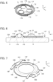
FIG. 4 is a perspective view showing a ball retention member in the embodiment. -
FIG. 5 is a perspective view showing a spring member of a ball guide portion in the embodiment. -
FIG. 6 is a cross-sectional view showing a ball, the ball retention member, and the spring member in the embodiment. -
FIG. 7 is a perspective view showing a cover member of the ball guide portion in the embodiment. -
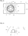
FIG. 8 is a plan view showing the ball assembly in the embodiment. -
FIG. 9 is a perspective view showing a second end portion of a return spring inserted in an insertion hole of the cover member in the embodiment. -
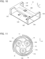
FIG. 10 is a perspective view showing a shell in the embodiment. -
FIG. 11 is an enlarged view of a main part ofFIG. 8 . -
FIG. 12 is a cross-sectional view showing a conventional connector. -
FIG. 13 is a plan view showing a contact holder and three metal balls of the conventional connector. - An embodiment of the present invention is described below based on the accompanying drawings.
-
FIG. 1 shows aconnector 11 according to the embodiment and acounter connector terminal 21 to be inserted into theconnector 11. Theconnector 11 includes aconnector terminal 12 to be electrically connected to thecounter connector terminal 21, and ashell 13 illustrated by broken lines is attached to theconnector terminal 12. - The
counter connector terminal 21 is formed of a plug contact having a flat plate shape. Theconnector terminal 12 is formed of a socket contact having a flat plate shape as with thecounter connector terminal 21, and has aflat connection surface 12A. - For convenience, the
flat connection surface 12A of theconnector terminal 12 is defined as extending along an XY plane, the direction in which thecounter connector terminal 21 is inserted with respect to theconnector 11 is defined as a +Y direction, and the direction perpendicular to theconnection surface 12A of theconnector terminal 12 is defined as a Z direction. - As shown in
FIG. 2 , a ball assembly BA used for electrically connecting theconnector terminal 12 and thecounter connector terminal 21 together is mounted on theconnection surface 12A of theconnector terminal 12. The ball assembly BA includes threeballs 14 that relay electrical connection between theconnector terminal 12 and thecounter connector terminal 21, aball retention member 15 that rotatably retains the threeballs 14, and aball guide portion 16 that movably retains theball retention member 15 along theconnection surface 12A. -
FIG. 3 shows an assembly view of the ball assembly BA. The threeballs 14 are disposed on the +Z direction side of theconnection surface 12A of theconnector terminal 12, theball retention member 15 is disposed on the +Z direction side of the threeballs 14, and aspring member 17 and acover member 18 that constitute theball guide portion 16 are sequentially disposed on the +Z direction side of theball retention member 15. - The three
balls 14 are arranged such that all theballs 14 are not aligned in a straight line in an XY plane. In other words, in one example of the embodiment, the threeballs 14 are arranged such that the shape formed by connecting the centers of theballs 14 is a triangle in an XY plane. The threeballs 14 have a spherical shape having the same diameter and are made of, for instance, electrically conductive metal. It is sufficient for theballs 14 that at least their surfaces are electrically conductive, and for instance, use may be made of balls in each of which an electrically conductive metal layer is formed on a surface of a spherical member made of a nonconductor. - As shown in
FIG. 4 , theball retention member 15 is formed of a plate member made of metal or another material, and includes abase portion 15A of disc shape extending along an XY plane and threeprojection portions 15B projecting in the +Z direction from a surface of thebase portion 15A. The threeprojection portions 15B are arranged at positions of the three vertices of an equilateral triangle whose center corresponds to the center of thebase portion 15A of disc shape. Eachprojection portion 15B has acone surface 15C tapering toward the +Z direction and is provided with acircular opening 15D at its +Z directional end. - The
ball retention member 15 as above is fabricated by, for example, shearing and drawing a flat metal plate, and the threeballs 14 can be housed in three recess portions formed on the -Z direction side of the threeprojection portions 15B. - As shown in
FIG. 5 , thespring member 17 is a plate-like member made of metal or another material, and includes abase portion 17A of equilateral triangular shape extending along an XY plane, threeframe portions 17B of arc shape separately joined to thebase portion 17A, and threereturn springs 17C extending separately from the threeframe portions 17B. Thespring member 17 is fabricated by, for example, shearing a flat metal plate. - The three
frame portions 17B of arc shape are disposed at positions of the three vertices of thebase portion 17A of equilateral triangular shape, and eachframe portion 17B in combination with an arc edge portion of thebase portion 17A forms acircular opening portion 17D. Thespring member 17 is configured to be fitted to theball retention member 15 by inserting the threeprojection portions 15B of theball retention member 15 into the three openingportions 17D formed by the threeframe portions 17B, and thebase portion 17A and the threeframe portions 17B constitute afitting portion 17E that is fitted to theball retention member 15. - The three
return springs 17C are formed of band members having the same shape, have a spiral shape extending around the outside of thebase portion 17A and the threeframe portions 17B, and are elastically deformable in an XY plane. Eachreturn spring 17C includes a first end portion T1 joined to thecorresponding frame portion 17B of thefitting portion 17E and a second end portion T2 that is a free end. The second end portion T2 is provided with abent portion 17F bent toward the +Z direction. - Since the
return springs 17C each have a spiral shape, a longer spring length can be ensured while an installation space for thespring member 17 is minimized, and a spring constant can be easily adjusted. - In the ball assembly BA, the
ball retention member 15 is disposed such that the surface, on the -Z direction side, of thebase portion 15A makes contact with theconnection surface 12A of theconnector terminal 12 with theballs 14 being housed inball housing portions 15E of recess shape formed on the -Z direction side of therespective projection portions 15B, as shown inFIG. 6 . - The
circular opening 15D formed at the +Z directional end of eachprojection portion 15B of theball retention member 15 is situated higher than the height corresponding to the radius of theball 14 and lower than the height corresponding to the diameter of theball 14 in the +Z direction from theconnection surface 12A of theconnector terminal 12, and has a smaller diameter than that of theball 14. Owing to this configuration, theball 14 housed in theball housing portion 15E can rotate within theball housing portion 15E without coming out of theball housing portion 15E. - Since the
projection portion 15B of theball retention member 15 has theopening 15D as above, the -Z directional end of theball 14 housed in theball housing portion 15E surrounded by theconnection surface 12A of theconnector terminal 12 and theprojection portion 15B makes contact with theconnection surface 12A, while the +Z directional end of theball 14 protrudes from theopening 15D in the +Z direction, as shown inFIG. 6 . - The
spring member 17 is disposed on theball retention member 15, and the three openingportions 17D formed by the threeframe portions 17B make contact separately with the cone surfaces 15C of the threeprojection portions 15B of theball retention member 15, whereby thefitting portion 17E of thespring member 17 is fitted to theball retention member 15. Thefitting portion 17E of thespring member 17, theball retention member 15, and the threeballs 14 are configured to be integrally movable in a two-dimensional manner along theconnection surface 12A of theconnector terminal 12. - As shown in
FIG. 7 , thecover member 18 is formed of a plate member made of, for example, metal and includes acover body 18A in a frame shape extending along an XY plane, a pair of fixingportions 18B joined to the opposite ends, in the X direction, of thecover body 18A, and a pair of counter connectorterminal guide portions 18C joined to the pair of fixingportions 18B. - The
cover body 18A has the shape of a ring having in its center acircular opening portion 18D. A circular outer peripheral portion of thecover body 18A extends along an XY plane, while an inner peripheral portion of thecover body 18A adjacent to theopening portion 18D extends along an XY plane at a height situated on the +Z direction side of the outer peripheral portion. In other words, thecover body 18A has such a shape as to bulge in the +Z direction from the outer peripheral portion toward the inner peripheral portion as a whole. However, the thickness of thecover body 18A in the Z direction has a smaller dimension than the diameter of theball 14. - The ring-shaped
cover body 18A is provided withinsertion holes 18E penetrating thecover body 18A in the Z direction at rotational positions spaced at 120-degree intervals about the central axis of thecover body 18A extending in the Z direction. - The pair of fixing
portions 18B are used to fix thecover member 18 to theconnection surface 12A of theconnector terminal 12 and extend in the X direction along an XY plane separately from the +X directional end and the -X directional end of thecover body 18A. - The pair of counter connector
terminal guide portions 18C joined to the pair of fixingportions 18B are used to guide thecounter connector terminal 21 when thecounter connector terminal 21 is inserted into theconnector 11 as shown inFIG. 1 . Each counter connectorterminal guide portion 18C extends in the +Y direction and the -Y direction from the corresponding fixingportion 18B and is formed of a pair ofarm portions 18F that are curved in the Z direction. - As shown in
FIG. 8 , thecover member 18 is disposed on theconnection surface 12A of theconnector terminal 12 to cover thespring member 17 that is fitted to theball retention member 15 by thefitting portion 17E. InFIG. 8 , thecover member 18 is illustrated by dashed lines to show portions covered with thecover member 18. - The three
return springs 17C of thespring member 17 have a spiral shape extending along the outer peripheral portion of theball retention member 15 on theconnection surface 12A of theconnector terminal 12 and are situated on the -Z direction side of thecover body 18A of thecover member 18, and the +Z directional ends of the threeballs 14 retained in theball retention member 15 are exposed through theopening portion 18D of thecover member 18. In addition, since the thickness of thecover body 18A in the Z direction has a smaller dimension than the diameter of theball 14, the +Z directional ends of the threeballs 14 protrude in the +Z direction from thecover member 18. - Further, as shown in
FIG. 9 , thebent portion 17F formed at the second end portion T2 of eachreturn spring 17C of thespring member 17 is inserted in thecorresponding insertion hole 18E of thecover body 18A of thecover member 18. Owing to this configuration, the positions of the second end portions T2 of the threereturn springs 17C are restricted. - Accordingly, when, for instance, the
connector terminal 12 is disposed with theconnection surface 12A being a horizontal surface and no external force other than gravity acts on thespring member 17, theball retention member 15, and the threeballs 14, as shown inFIG. 8 , the threereturn springs 17C of thespring member 17 lie in a rotationally symmetrical arrangement along theconnection surface 12A, and theball retention member 15 is in an initial position P1 in which the center of thebase portion 15A of disc shape substantially coincides with the center of thecircular opening portion 18D of thecover member 18. - The
insertion hole 18E of thecover body 18A of thecover member 18 is formed to be larger than thebent portion 17F at the second end portion T2 of thereturn spring 17C as shown inFIG. 9 such that thebent portion 17F is inserted in theinsertion hole 18E with an extra margin. - The
shell 13 is formed of a plate member such as a bent metal plate as shown inFIG. 10 and includes abottom plate portion 13A situated on the -Z direction side and extending along an XY plane, atop plate portion 13B situated on the +Z direction side and extending along an XY plane, afront plate portion 13C situated on the -Y direction side and extending along an XZ plane, and arear plate portion 13D situated on the +Y direction side and extending along an XZ plane. - The
front plate portion 13C and therear plate portion 13D are respectively provided with openingportions counter connector terminal 21 is to be inserted. Aterminal spring 13G extending while being bent in the -Z direction and the +Y direction is formed at the -Y directional end of thetop plate portion 13B. - The height of the
top plate portion 13B with respect to thebottom plate portion 13A in the Z direction has a larger dimension than the sum of the thickness of theconnector terminal 12 in the Z direction, the thickness of thecounter connector terminal 21 in the Z direction, and the diameter of theball 14. - The
shell 13 is attached to theconnector terminal 12 such that theconnector terminal 12 is situated inside theshell 13 to be in contact with thebottom plate portion 13A of theshell 13, and a counter connectorterminal housing portion 13H to which thecounter connector terminal 21 is to be inserted is formed between theterminal spring 13G and theconnection surface 12A of theconnector terminal 12. - When the
connector 11 is assembled, first, theball retention member 15 is disposed on theconnection surface 12A of theconnector terminal 12 while theballs 14 are separately housed in the threeball housing portions 15E of theball retention member 15 as shown inFIG. 6 . At this time, thebase portion 15A of theball retention member 15 makes contact with theconnection surface 12A of theconnector terminal 12. - Next, the
spring member 17 is disposed on theball retention member 15 such that the three openingportions 17D of thespring member 17 make contact with the cone surfaces 15C of the correspondingprojection portions 15B of theball retention member 15, and thefitting portion 17E of thespring member 17 is fitted to theball retention member 15. - Further, the
cover member 18 is put over theball retention member 15 and thespring member 17 as shown inFIG. 8 , and thebent portions 17F of the threereturn springs 17C of thespring member 17 are inserted into thecorresponding insertion holes 18E of thecover body 18A of thecover member 18 as shown inFIG. 9 . - In this state, the pair of fixing
portions 18B of thecover member 18 are, in plural positions, welded to theconnection surface 12A of theconnector terminal 12 by laser welding or another method, whereby thecover member 18 is fixed to theconnector terminal 12. Consequently, thefitting portion 17E of thespring member 17, theball retention member 15, and the threeballs 14 are integrally movable along theconnection surface 12A of theconnector terminal 12 within thecover member 18, and the +Z directional ends of the threeballs 14 retained in theball retention member 15 are exposed through theopening portion 18D of thecover member 18. - After the ball assembly BA is mounted on the
connection surface 12A of theconnector terminal 12 in this manner, theshell 13 is attached to theconnector terminal 12 such that the surface, on the -Z directional side, of theconnector terminal 12 makes contact with thebottom plate portion 13A of theshell 13. Thus, the assembling operation of theconnector 11 is completed. - It should be noted that since the
insertion hole 18E of thecover member 18 is formed to be larger than thebent portion 17F of thereturn spring 17C as shown inFIG. 9 , thebent portion 17F can be inserted into theinsertion hole 18E with an extra margin, which facilitates the assembling operation of theconnector 11. - Next, the operation of the
connector 11 is described. - To electrically connect the
counter connector terminal 21 to theconnector terminal 12 of theconnector 11, thecounter connector terminal 21 shown inFIG. 1 is moved from the -Y direction toward the +Y direction and inserted into theshell 13 of theconnector 11. - In this process, the
counter connector terminal 21 is inserted into theshell 13 while being guided by the pair of counter connectorterminal guide portions 18C of thecover member 18 shown inFIG. 7 to be parallel to theconnection surface 12A of theconnector terminal 12, and a +Y directional end portion of thecounter connector terminal 21 is inserted into the counter connectorterminal housing portion 13H formed between theterminal spring 13G of theshell 13 shown inFIG. 10 and theconnection surface 12A of theconnector terminal 12 while elastically compressing theterminal spring 13G toward the +Z direction, and is thereby pressed by theterminal spring 13G against theconnection surface 12A of theconnector terminal 12 in the -Z direction. - As a consequence, the surface of the
counter connector terminal 21 on the -Z direction side makes contact at a predetermined contact pressure with the +Z directional ends of the threeballs 14 protruding from thecover member 18 in the +Z direction, the threeballs 14 being retained in theball retention member 15, and this allows the -Z directional ends of the threeballs 14 to contact theconnection surface 12A of theconnector terminal 12 at the predetermined contact pressure. - Thus, the
counter connector terminal 21 and theconnector terminal 12 are electrically connected to each other via the threeballs 14. - The three
balls 14 contact the surface, on the -Z direction side, of thecounter connector terminal 21 and theconnection surface 12A of theconnector terminal 12 at the predetermined contact pressure and, accordingly, are urged to move in the +Y direction while rotating with the insertion movement of thecounter connector terminal 21 into the counter connectorterminal housing portion 13H. - However, the positions of the second end portions T2 of the three
return springs 17C are separately restricted because thebent portions 17F formed at the second end portions T2 of the respective return springs 17C of thespring member 17 are inserted in thecorresponding insertion holes 18E of thecover member 18. Accordingly, theball retention member 15 being in the initial position P1 as shown inFIG. 8 before insertion of thecounter connector terminal 21 moves together with the threeballs 14 in the +Y direction along theconnection surface 12A of theconnector terminal 12 while elastically deforming each of the threereturn springs 17C. - The three
balls 14 disposed between thecounter connector terminal 21 and theconnector terminal 12 thus move in the +Y direction while rotating, and this makes it possible to reduce the sliding resistance associated with insertion of thecounter connector terminal 21 into the counter connectorterminal housing portion 13H. - Likewise, the sliding resistance can be reduced also when the
counter connector terminal 21 connected to theconnector terminal 12 is pulled out from the counter connectorterminal housing portion 13H. - Further, since the
ball retention member 15 is held to be movable on theconnection surface 12A of theconnector terminal 12 not only in the Y direction but in a two-dimensional manner in an XY plane, when thecounter connector terminal 21 is inserted into or pulled out from the counter connectorterminal housing portion 13H, if thecounter connector terminal 21 moves relative to theconnector terminal 12 in a direction different from the Y direction, the threeballs 14 also move in the same direction as the direction of movement of thecounter connector terminal 21, thereby reducing the sliding resistance. - Since the three
return springs 17C of thespring member 17 lie in a rotationally symmetrical arrangement along theconnection surface 12A of theconnector terminal 12 when theball retention member 15 is in the initial position P1, no matter which direction theball retention member 15 is going to move in an XY plane, equal elastic forces act from the threereturn springs 17C to theball retention member 15, so that theball retention member 15 can smoothly move regardless of the moving direction. - Thus, no matter which direction the
counter connector terminal 21 moves relative to theconnector terminal 12, the sliding resistance can be effectively reduced. - Aside from that, the
counter connector terminal 21 may move relative to theconnector terminal 12 not only when it is inserted into or pulled out from the counter connectorterminal housing portion 13H but also in the connected state with theconnector terminal 12 because of an external force such as vibration acting on theconnector 11. Even in such cases, theball retention member 15 can move together with the threeballs 14 in the same direction as the direction of movement of thecounter connector terminal 21 regardless of which direction thecounter connector terminal 21 moves relative to theconnector terminal 12. Thus, the sliding resistance can be reduced, and theconnector terminal 12 and thecounter connector terminal 21 can be electrically connected to each other with high reliability. - Meanwhile, the three
return springs 17C of thespring member 17 do not necessarily need to lie in a rotationally symmetrical arrangement along theconnection surface 12A of theconnector terminal 12 when theball retention member 15 is in the initial position P1; as long as the threereturn springs 17C are arranged to surround theball retention member 15, substantially equal elastic forces act on theball retention member 15 owing to the threereturn springs 17C, so that theball retention member 15 can smoothly move, thus reducing the sliding resistance. - However, it is preferable that the three
return springs 17C lie in a rotationally symmetrical arrangement as shown inFIG. 8 because this allows equal elastic forces to act on theball retention member 15 in an XY plane regardless of which direction theball retention member 15 moves. - When the connected state between the
connector terminal 12 and thecounter connector terminal 21 is released and thecounter connector terminal 21 is pulled out from the counter connectorterminal housing portion 13H, theball retention member 15 returns to the initial position P1 shown inFIG. 8 along theconnection surface 12A of theconnector terminal 12 due to the action of the threereturn springs 17C. - Aside from that, in the
connector 11 according to the embodiment, thespring member 17 is configured such that the center of gravity G of thespring member 17 is situated inside a region R of triangular shape surrounded by thecenters 14A of the threerespective balls 14 retained in theball retention member 15 as shown inFIG. 11 . Owing to this configuration, the threeballs 14 can rotate and smoothly move on theconnection surface 12A of theconnector terminal 12 together with theball retention member 15 and thebase portion 17A of thespring member 17 when thecounter connector terminal 21 moves relative to theconnector terminal 12, so that the sliding resistance is effectively reduced, thus improving the reliability of electrical connection between theconnector terminal 12 and thecounter connector terminal 21. - The center of gravity G of the
spring member 17 does not necessarily need to be situated inside the region R surrounded by thecenters 14A of the threerespective balls 14 retained in theball retention member 15 and may be situated outside the region R. However, when the center of gravity G of thespring member 17 is situated outside the region R, unequal forces tend to act on the threeballs 14, and this may make it difficult to smoothly rotate the threeballs 14; therefore, it is preferable that the center of gravity G of thespring member 17 be situated inside the region R. The expression "inside the region R" herein includes a position on the boundary of the region R. - While the three
balls 14 are retained in theball retention member 15 in the embodiment above, the number of theballs 14 is not limited to three, and two or four ormore balls 14 may be retained. - Even when such
plural balls 14 are retained in theball retention member 15, the center of gravity G of thespring member 17 is preferably situated inside the region R surrounded by thecenters 14A of the pluralrespective balls 14. When the number of theballs 14 is two, a straight line connecting thecenters 14A of the tworespective balls 14 is regarded as the "region R," and the center of gravity G of thespring member 17 is preferably situated on the straight line. - In the embodiment above, the three
balls 14 are retained in theball retention member 15, and thespring member 17 has the threereturn springs 17C correspondingly; thus, the number of the return springs 17C is the same as the number of theballs 14, but the invention is not limited thereto. However, the number of the return springs 17C is preferably greater than or equal to the number of theballs 14 because with this configuration, elastic forces acting from plural return springs 17C toplural balls 14 via theball retention member 15 are more likely to be equal, and this allows theplural balls 14 to stably rotate regardless of the moving direction. - In the embodiment above, the
terminal spring 13G of theshell 13 contacts thecounter connector terminal 21 inserted in the counter connectorterminal housing portion 13H and presses thecounter connector terminal 21 against theconnection surface 12A of theconnector terminal 12; however, the invention is not limited thereto. - It is sufficient that the
shell 13 has a terminal spring that presses thecounter connector terminal 21 inserted in the counter connectorterminal housing portion 13H and/or theconnection surface 12A of theconnector terminal 12 in a direction closer together. For instance, it may be configured such that theconnector terminal 12 is pressed against thecounter connector terminal 21 by a terminal spring to allowplural balls 14 to contact the surface, on the -Z direction side, of thecounter connector terminal 21 and theconnection surface 12A of theconnector terminal 12 at a predetermined contact pressure.
Claims (10)
- A connector (11) having a counter connector terminal housing portion (13H) in which part of a counter connector terminal (21) is inserted, the connector comprising:a connector terminal (12) having a connection surface (12A) in a flat shape that faces the counter connector terminal inserted in the counter connector terminal housing portion;a plurality of balls (14) in a spherical shape being disposed on the connection surface, at least surfaces of the plurality of balls having electrical conductivity;a ball retention member (15) rotatably retaining the plurality of balls in such a manner part of the surfaces of the plurality of balls contacts the connection surface and another part of the surfaces of the plurality of balls that faces opposite from the connection surface protrudes;a ball guide portion (16) fixed to the connector terminal and retaining the ball retention member such that the ball retention member is movable in a two-dimensional manner along the connection surface; anda terminal spring (13G) pressing the counter connector terminal inserted in the counter connector terminal housing portion or the connection surface of the connector terminal in a direction closer together,wherein the ball guide portion includes a plurality of return springs (17C) that are disposed to surround the ball retention member along the connection surface and act to return the ball retention member to an initial position (P1) on the connection surface,the ball retention member moves in a two-dimensional manner along the connection surface in accordance with movement of the counter connector terminal when the counter connector terminal is inserted into the counter connector terminal housing portion and in a connected state between the counter connector terminal and the connector terminal, and the ball retention member returns to the initial position due to action of the plurality of return springs when the counter connector terminal is pulled out from the counter connector terminal housing portion, andthe counter connector terminal inserted in the counter connector terminal housing portion is pressed against the connection surface by the terminal spring, contacts protruding parts of the surfaces of the plurality of balls retained in the ball retention member, and is electrically connected to the connector terminal via the plurality of balls.
- The connector according to claim 1,
wherein the plurality of return springs (17C) lie in a rotationally symmetrical arrangement along the connection surface (12A) when the ball retention member is in the initial position. - The connector according to claim 1 or 2,
wherein the ball guide portion (16) includes:a cover member (18) in a frame shape that is fixed to the connector terminal and has an opening portion through which the plurality of balls retained in the ball retention member are exposed; anda spring member (17) having the plurality of return springs, fitted to the ball retention member and retained by the cover member. - The connector according to claim 3,wherein the spring member (17) includes a fitting portion (17E) fitted to the ball retention member,the cover member (18) has a plurality of insertion holes (18E) formed to correspond to the plurality of return springs, andeach of the plurality of return springs (17C) has a first end portion (T1) joined to the fitting portion and a second end portion (T2) inserted in a corresponding one of the plurality of insertion holes of the cover member so that its position is restricted.
- The connector according to claim 4,
wherein each of the plurality of return springs (17C) has a spiral shape extending along an outer peripheral portion of the ball retention member (15). - The connector according to any one of claims 3-5,
wherein a center of gravity of the spring member (17) is situated inside a region surrounded by centers of the plurality of balls (14). - The connector according to claim 6,
wherein the plurality of balls consist of three balls (14) disposed on the connection surface (12A) so as not to be aligned in a straight line. - The connector according to any one of claims 1-7,
wherein the number of the plurality of return springs (17C) is greater than or equal to the number of the plurality of balls (14). - The connector according to any one of claims 1-8,wherein the ball retention member (15) is formed of a plate member provided with a plurality of ball housing portions (15E) of recess shape in which the plurality of balls are separately housed, andeach of the plurality of ball housing portions has an opening (15D) through which part of a corresponding one of the plurality of balls housed protrudes in a direction opposite from the connection surface.
- The connector according to any one of claims 1-9, comprising a shell (13) attached to the connector terminal and retaining the terminal spring (13G) such that the terminal spring faces the connection surface,
wherein the counter connector terminal housing portion (13H) is formed between the terminal spring and the connection surface.
Applications Claiming Priority (1)
| Application Number | Priority Date | Filing Date | Title |
|---|---|---|---|
| JP2023073220A JP2024158213A (en) | 2023-04-27 | 2023-04-27 | connector |
Publications (2)
| Publication Number | Publication Date |
|---|---|
| EP4456333A1 true EP4456333A1 (en) | 2024-10-30 |
| EP4456333B1 EP4456333B1 (en) | 2025-06-04 |
Family
ID=90344875
Family Applications (1)
| Application Number | Title | Priority Date | Filing Date |
|---|---|---|---|
| EP24164122.4A Active EP4456333B1 (en) | 2023-04-27 | 2024-03-18 | Connector |
Country Status (4)
| Country | Link |
|---|---|
| US (1) | US20240364048A1 (en) |
| EP (1) | EP4456333B1 (en) |
| JP (1) | JP2024158213A (en) |
| CN (1) | CN118867723A (en) |
Citations (3)
| Publication number | Priority date | Publication date | Assignee | Title |
|---|---|---|---|---|
| JP2019067499A (en) | 2017-09-28 | 2019-04-25 | 株式会社オートネットワーク技術研究所 | connector |
| JP2019083146A (en) * | 2017-10-31 | 2019-05-30 | 株式会社オートネットワーク技術研究所 | Terminal unit |
| EP4207504A1 (en) * | 2021-12-28 | 2023-07-05 | Japan Aviation Electronics Industry, Limited | Connector |
-
2023
- 2023-04-27 JP JP2023073220A patent/JP2024158213A/en active Pending
-
2024
- 2024-01-23 CN CN202410094075.4A patent/CN118867723A/en active Pending
- 2024-03-12 US US18/602,692 patent/US20240364048A1/en active Pending
- 2024-03-18 EP EP24164122.4A patent/EP4456333B1/en active Active
Patent Citations (4)
| Publication number | Priority date | Publication date | Assignee | Title |
|---|---|---|---|---|
| JP2019067499A (en) | 2017-09-28 | 2019-04-25 | 株式会社オートネットワーク技術研究所 | connector |
| DE112018005516T5 (en) * | 2017-09-28 | 2020-07-02 | Autonetworks Technologies, Ltd. | Interconnects |
| JP2019083146A (en) * | 2017-10-31 | 2019-05-30 | 株式会社オートネットワーク技術研究所 | Terminal unit |
| EP4207504A1 (en) * | 2021-12-28 | 2023-07-05 | Japan Aviation Electronics Industry, Limited | Connector |
Also Published As
| Publication number | Publication date |
|---|---|
| CN118867723A (en) | 2024-10-29 |
| JP2024158213A (en) | 2024-11-08 |
| US20240364048A1 (en) | 2024-10-31 |
| EP4456333B1 (en) | 2025-06-04 |
Similar Documents
| Publication | Publication Date | Title |
|---|---|---|
| KR100433704B1 (en) | Connector excellent in reliability of contact | |
| US8172591B2 (en) | Electrical connector assembly having electrical connector with low profile and processor with cone pins | |
| JP7465433B2 (en) | connector | |
| JP7109303B2 (en) | connector assembly | |
| EP4207504A1 (en) | Connector | |
| JP3337650B2 (en) | Coaxial connector with switch | |
| US7320623B2 (en) | Connector with protection against electrostatic charges accumulated on a mating connector | |
| CN102904086B (en) | Connector, and performance plate, mother plate and a semiconductor testing device containing same | |
| US3206717A (en) | Connector assembly | |
| CN106981743A (en) | Middle relay connector and electrical connection assembly | |
| US6162103A (en) | Terminal structure of a connector | |
| US6439934B1 (en) | High-speed electrical connector | |
| US20240283203A1 (en) | Low profile board-to-board interface contactors | |
| JP2020184415A (en) | connector | |
| JP2021077599A (en) | Connector device | |
| CN112563774B (en) | Connector with a locking member | |
| EP4456333B1 (en) | Connector | |
| JP7123213B1 (en) | board mount connector | |
| US7037125B1 (en) | Memory card connector | |
| CN102437439B (en) | Electric connector for cable, and assembly of electric connector for cable | |
| JP7549297B2 (en) | Floating connector | |
| JP7392688B2 (en) | connector set | |
| JP7534036B2 (en) | Contact member for an IDC terminal, contact member assembly, set of contact members, and housing with contact members | |
| EP1420489A1 (en) | Hinge connector, and circuit board connected to connector | |
| JP2026080261A (en) | Connectors and connector assemblies |
Legal Events
| Date | Code | Title | Description |
|---|---|---|---|
| PUAI | Public reference made under article 153(3) epc to a published international application that has entered the european phase |
Free format text: ORIGINAL CODE: 0009012 |
|
| STAA | Information on the status of an ep patent application or granted ep patent |
Free format text: STATUS: REQUEST FOR EXAMINATION WAS MADE |
|
| 17P | Request for examination filed |
Effective date: 20240318 |
|
| AK | Designated contracting states |
Kind code of ref document: A1 Designated state(s): AL AT BE BG CH CY CZ DE DK EE ES FI FR GB GR HR HU IE IS IT LI LT LU LV MC ME MK MT NL NO PL PT RO RS SE SI SK SM TR |
|
| RBV | Designated contracting states (corrected) |
Designated state(s): AL AT BE BG CH CY CZ DE DK EE ES FI FR GB GR HR HU IE IS IT LI LT LU LV MC ME MK MT NL NO PL PT RO RS SE SI SK SM TR |
|
| GRAP | Despatch of communication of intention to grant a patent |
Free format text: ORIGINAL CODE: EPIDOSNIGR1 |
|
| STAA | Information on the status of an ep patent application or granted ep patent |
Free format text: STATUS: GRANT OF PATENT IS INTENDED |
|
| RIC1 | Information provided on ipc code assigned before grant |
Ipc: H01R 13/24 20060101ALN20250122BHEP Ipc: H01R 13/14 20060101ALN20250122BHEP Ipc: H01R 13/11 20060101ALN20250122BHEP Ipc: H01R 4/50 20060101AFI20250122BHEP |
|
| INTG | Intention to grant announced |
Effective date: 20250203 |
|
| RIC1 | Information provided on ipc code assigned before grant |
Ipc: H01R 13/24 20060101ALN20250128BHEP Ipc: H01R 13/14 20060101ALN20250128BHEP Ipc: H01R 13/11 20060101ALN20250128BHEP Ipc: H01R 4/50 20060101AFI20250128BHEP |
|
| GRAS | Grant fee paid |
Free format text: ORIGINAL CODE: EPIDOSNIGR3 |
|
| GRAA | (expected) grant |
Free format text: ORIGINAL CODE: 0009210 |
|
| STAA | Information on the status of an ep patent application or granted ep patent |
Free format text: STATUS: THE PATENT HAS BEEN GRANTED |
|
| AK | Designated contracting states |
Kind code of ref document: B1 Designated state(s): AL AT BE BG CH CY CZ DE DK EE ES FI FR GB GR HR HU IE IS IT LI LT LU LV MC ME MK MT NL NO PL PT RO RS SE SI SK SM TR |
|
| REG | Reference to a national code |
Ref country code: GB Ref legal event code: FG4D |
|
| REG | Reference to a national code |
Ref country code: CH Ref legal event code: EP |
|
| REG | Reference to a national code |
Ref country code: DE Ref legal event code: R096 Ref document number: 602024000172 Country of ref document: DE |
|
| REG | Reference to a national code |
Ref country code: IE Ref legal event code: FG4D |
|
| REG | Reference to a national code |
Ref country code: NL Ref legal event code: MP Effective date: 20250604 |
|
| PG25 | Lapsed in a contracting state [announced via postgrant information from national office to epo] |
Ref country code: ES Free format text: LAPSE BECAUSE OF FAILURE TO SUBMIT A TRANSLATION OF THE DESCRIPTION OR TO PAY THE FEE WITHIN THE PRESCRIBED TIME-LIMIT Effective date: 20250604 Ref country code: FI Free format text: LAPSE BECAUSE OF FAILURE TO SUBMIT A TRANSLATION OF THE DESCRIPTION OR TO PAY THE FEE WITHIN THE PRESCRIBED TIME-LIMIT Effective date: 20250604 |
|
| REG | Reference to a national code |
Ref country code: LT Ref legal event code: MG9D |
|
| PG25 | Lapsed in a contracting state [announced via postgrant information from national office to epo] |
Ref country code: NO Free format text: LAPSE BECAUSE OF FAILURE TO SUBMIT A TRANSLATION OF THE DESCRIPTION OR TO PAY THE FEE WITHIN THE PRESCRIBED TIME-LIMIT Effective date: 20250904 Ref country code: GR Free format text: LAPSE BECAUSE OF FAILURE TO SUBMIT A TRANSLATION OF THE DESCRIPTION OR TO PAY THE FEE WITHIN THE PRESCRIBED TIME-LIMIT Effective date: 20250905 |
|
| PG25 | Lapsed in a contracting state [announced via postgrant information from national office to epo] |
Ref country code: PL Free format text: LAPSE BECAUSE OF FAILURE TO SUBMIT A TRANSLATION OF THE DESCRIPTION OR TO PAY THE FEE WITHIN THE PRESCRIBED TIME-LIMIT Effective date: 20250604 |
|
| PG25 | Lapsed in a contracting state [announced via postgrant information from national office to epo] |
Ref country code: BG Free format text: LAPSE BECAUSE OF FAILURE TO SUBMIT A TRANSLATION OF THE DESCRIPTION OR TO PAY THE FEE WITHIN THE PRESCRIBED TIME-LIMIT Effective date: 20250604 |
|
| PG25 | Lapsed in a contracting state [announced via postgrant information from national office to epo] |
Ref country code: HR Free format text: LAPSE BECAUSE OF FAILURE TO SUBMIT A TRANSLATION OF THE DESCRIPTION OR TO PAY THE FEE WITHIN THE PRESCRIBED TIME-LIMIT Effective date: 20250604 |
|
| PG25 | Lapsed in a contracting state [announced via postgrant information from national office to epo] |
Ref country code: RS Free format text: LAPSE BECAUSE OF FAILURE TO SUBMIT A TRANSLATION OF THE DESCRIPTION OR TO PAY THE FEE WITHIN THE PRESCRIBED TIME-LIMIT Effective date: 20250904 |
|
| PG25 | Lapsed in a contracting state [announced via postgrant information from national office to epo] |
Ref country code: LV Free format text: LAPSE BECAUSE OF FAILURE TO SUBMIT A TRANSLATION OF THE DESCRIPTION OR TO PAY THE FEE WITHIN THE PRESCRIBED TIME-LIMIT Effective date: 20250604 |
|
| PG25 | Lapsed in a contracting state [announced via postgrant information from national office to epo] |
Ref country code: NL Free format text: LAPSE BECAUSE OF FAILURE TO SUBMIT A TRANSLATION OF THE DESCRIPTION OR TO PAY THE FEE WITHIN THE PRESCRIBED TIME-LIMIT Effective date: 20250604 |
|
| PG25 | Lapsed in a contracting state [announced via postgrant information from national office to epo] |
Ref country code: PT Free format text: LAPSE BECAUSE OF FAILURE TO SUBMIT A TRANSLATION OF THE DESCRIPTION OR TO PAY THE FEE WITHIN THE PRESCRIBED TIME-LIMIT Effective date: 20251006 |
|
| REG | Reference to a national code |
Ref country code: AT Ref legal event code: MK05 Ref document number: 1801308 Country of ref document: AT Kind code of ref document: T Effective date: 20250604 |
|
| PG25 | Lapsed in a contracting state [announced via postgrant information from national office to epo] |
Ref country code: IS Free format text: LAPSE BECAUSE OF FAILURE TO SUBMIT A TRANSLATION OF THE DESCRIPTION OR TO PAY THE FEE WITHIN THE PRESCRIBED TIME-LIMIT Effective date: 20251004 |
|
| PG25 | Lapsed in a contracting state [announced via postgrant information from national office to epo] |
Ref country code: SM Free format text: LAPSE BECAUSE OF FAILURE TO SUBMIT A TRANSLATION OF THE DESCRIPTION OR TO PAY THE FEE WITHIN THE PRESCRIBED TIME-LIMIT Effective date: 20250604 Ref country code: AT Free format text: LAPSE BECAUSE OF FAILURE TO SUBMIT A TRANSLATION OF THE DESCRIPTION OR TO PAY THE FEE WITHIN THE PRESCRIBED TIME-LIMIT Effective date: 20250604 |
|
| PG25 | Lapsed in a contracting state [announced via postgrant information from national office to epo] |
Ref country code: CZ Free format text: LAPSE BECAUSE OF FAILURE TO SUBMIT A TRANSLATION OF THE DESCRIPTION OR TO PAY THE FEE WITHIN THE PRESCRIBED TIME-LIMIT Effective date: 20250604 |
|
| PG25 | Lapsed in a contracting state [announced via postgrant information from national office to epo] |
Ref country code: EE Free format text: LAPSE BECAUSE OF FAILURE TO SUBMIT A TRANSLATION OF THE DESCRIPTION OR TO PAY THE FEE WITHIN THE PRESCRIBED TIME-LIMIT Effective date: 20250604 |
|
| PG25 | Lapsed in a contracting state [announced via postgrant information from national office to epo] |
Ref country code: SK Free format text: LAPSE BECAUSE OF FAILURE TO SUBMIT A TRANSLATION OF THE DESCRIPTION OR TO PAY THE FEE WITHIN THE PRESCRIBED TIME-LIMIT Effective date: 20250604 |
|
| PG25 | Lapsed in a contracting state [announced via postgrant information from national office to epo] |
Ref country code: IT Free format text: LAPSE BECAUSE OF FAILURE TO SUBMIT A TRANSLATION OF THE DESCRIPTION OR TO PAY THE FEE WITHIN THE PRESCRIBED TIME-LIMIT Effective date: 20250604 |
|
| REG | Reference to a national code |
Ref country code: DE Ref legal event code: R097 Ref document number: 602024000172 Country of ref document: DE |
|
| PLBE | No opposition filed within time limit |
Free format text: ORIGINAL CODE: 0009261 |
|
| STAA | Information on the status of an ep patent application or granted ep patent |
Free format text: STATUS: NO OPPOSITION FILED WITHIN TIME LIMIT |
|
| PG25 | Lapsed in a contracting state [announced via postgrant information from national office to epo] |
Ref country code: DK Free format text: LAPSE BECAUSE OF FAILURE TO SUBMIT A TRANSLATION OF THE DESCRIPTION OR TO PAY THE FEE WITHIN THE PRESCRIBED TIME-LIMIT Effective date: 20250604 |
|
| PGFP | Annual fee paid to national office [announced via postgrant information from national office to epo] |
Ref country code: DE Payment date: 20260128 Year of fee payment: 3 |
|
| REG | Reference to a national code |
Ref country code: CH Ref legal event code: L10 Free format text: ST27 STATUS EVENT CODE: U-0-0-L10-L00 (AS PROVIDED BY THE NATIONAL OFFICE) Effective date: 20260416 |
|
| 26N | No opposition filed |
Effective date: 20260305 |
|
| PG25 | Lapsed in a contracting state [announced via postgrant information from national office to epo] |
Ref country code: LT Free format text: LAPSE BECAUSE OF FAILURE TO SUBMIT A TRANSLATION OF THE DESCRIPTION OR TO PAY THE FEE WITHIN THE PRESCRIBED TIME-LIMIT Effective date: 20250604 |
|
| PG25 | Lapsed in a contracting state [announced via postgrant information from national office to epo] |
Ref country code: SE Free format text: LAPSE BECAUSE OF FAILURE TO SUBMIT A TRANSLATION OF THE DESCRIPTION OR TO PAY THE FEE WITHIN THE PRESCRIBED TIME-LIMIT Effective date: 20250604 |