EP4456308A1 - Connecting component, battery cell, battery and electric device - Google Patents
Connecting component, battery cell, battery and electric device Download PDFInfo
- Publication number
- EP4456308A1 EP4456308A1 EP22919951.8A EP22919951A EP4456308A1 EP 4456308 A1 EP4456308 A1 EP 4456308A1 EP 22919951 A EP22919951 A EP 22919951A EP 4456308 A1 EP4456308 A1 EP 4456308A1
- Authority
- EP
- European Patent Office
- Prior art keywords
- connecting portion
- connecting component
- welding
- electrode terminal
- groove
- Prior art date
- Legal status (The legal status is an assumption and is not a legal conclusion. Google has not performed a legal analysis and makes no representation as to the accuracy of the status listed.)
- Pending
Links
Images






Classifications
-
- H—ELECTRICITY
- H01—ELECTRIC ELEMENTS
- H01M—PROCESSES OR MEANS, e.g. BATTERIES, FOR THE DIRECT CONVERSION OF CHEMICAL ENERGY INTO ELECTRICAL ENERGY
- H01M50/00—Constructional details or processes of manufacture of the non-active parts of electrochemical cells other than fuel cells, e.g. hybrid cells
- H01M50/50—Current conducting connections for cells or batteries
- H01M50/531—Electrode connections inside a battery casing
- H01M50/533—Electrode connections inside a battery casing characterised by the shape of the leads or tabs
-
- H—ELECTRICITY
- H01—ELECTRIC ELEMENTS
- H01M—PROCESSES OR MEANS, e.g. BATTERIES, FOR THE DIRECT CONVERSION OF CHEMICAL ENERGY INTO ELECTRICAL ENERGY
- H01M50/00—Constructional details or processes of manufacture of the non-active parts of electrochemical cells other than fuel cells, e.g. hybrid cells
- H01M50/50—Current conducting connections for cells or batteries
- H01M50/502—Interconnectors for connecting terminals of adjacent batteries; Interconnectors for connecting cells outside a battery casing
- H01M50/514—Methods for interconnecting adjacent batteries or cells
- H01M50/516—Methods for interconnecting adjacent batteries or cells by welding, soldering or brazing
-
- H—ELECTRICITY
- H01—ELECTRIC ELEMENTS
- H01M—PROCESSES OR MEANS, e.g. BATTERIES, FOR THE DIRECT CONVERSION OF CHEMICAL ENERGY INTO ELECTRICAL ENERGY
- H01M50/00—Constructional details or processes of manufacture of the non-active parts of electrochemical cells other than fuel cells, e.g. hybrid cells
- H01M50/50—Current conducting connections for cells or batteries
- H01M50/543—Terminals
- H01M50/552—Terminals characterised by their shape
- H01M50/553—Terminals adapted for prismatic, pouch or rectangular cells
-
- H—ELECTRICITY
- H01—ELECTRIC ELEMENTS
- H01M—PROCESSES OR MEANS, e.g. BATTERIES, FOR THE DIRECT CONVERSION OF CHEMICAL ENERGY INTO ELECTRICAL ENERGY
- H01M50/00—Constructional details or processes of manufacture of the non-active parts of electrochemical cells other than fuel cells, e.g. hybrid cells
- H01M50/50—Current conducting connections for cells or batteries
- H01M50/543—Terminals
- H01M50/564—Terminals characterised by their manufacturing process
- H01M50/566—Terminals characterised by their manufacturing process by welding, soldering or brazing
-
- H—ELECTRICITY
- H01—ELECTRIC ELEMENTS
- H01M—PROCESSES OR MEANS, e.g. BATTERIES, FOR THE DIRECT CONVERSION OF CHEMICAL ENERGY INTO ELECTRICAL ENERGY
- H01M2220/00—Batteries for particular applications
- H01M2220/20—Batteries in motive systems, e.g. vehicle, ship, plane
-
- H—ELECTRICITY
- H01—ELECTRIC ELEMENTS
- H01M—PROCESSES OR MEANS, e.g. BATTERIES, FOR THE DIRECT CONVERSION OF CHEMICAL ENERGY INTO ELECTRICAL ENERGY
- H01M50/00—Constructional details or processes of manufacture of the non-active parts of electrochemical cells other than fuel cells, e.g. hybrid cells
- H01M50/20—Mountings; Secondary casings or frames; Racks, modules or packs; Suspension devices; Shock absorbers; Transport or carrying devices; Holders
- H01M50/204—Racks, modules or packs for multiple batteries or multiple cells
- H01M50/207—Racks, modules or packs for multiple batteries or multiple cells characterised by their shape
- H01M50/209—Racks, modules or packs for multiple batteries or multiple cells characterised by their shape adapted for prismatic or rectangular cells
-
- H—ELECTRICITY
- H01—ELECTRIC ELEMENTS
- H01M—PROCESSES OR MEANS, e.g. BATTERIES, FOR THE DIRECT CONVERSION OF CHEMICAL ENERGY INTO ELECTRICAL ENERGY
- H01M50/00—Constructional details or processes of manufacture of the non-active parts of electrochemical cells other than fuel cells, e.g. hybrid cells
- H01M50/50—Current conducting connections for cells or batteries
- H01M50/543—Terminals
- H01M50/547—Terminals characterised by the disposition of the terminals on the cells
- H01M50/55—Terminals characterised by the disposition of the terminals on the cells on the same side of the cell
-
- Y—GENERAL TAGGING OF NEW TECHNOLOGICAL DEVELOPMENTS; GENERAL TAGGING OF CROSS-SECTIONAL TECHNOLOGIES SPANNING OVER SEVERAL SECTIONS OF THE IPC; TECHNICAL SUBJECTS COVERED BY FORMER USPC CROSS-REFERENCE ART COLLECTIONS [XRACs] AND DIGESTS
- Y02—TECHNOLOGIES OR APPLICATIONS FOR MITIGATION OR ADAPTATION AGAINST CLIMATE CHANGE
- Y02E—REDUCTION OF GREENHOUSE GAS [GHG] EMISSIONS, RELATED TO ENERGY GENERATION, TRANSMISSION OR DISTRIBUTION
- Y02E60/00—Enabling technologies; Technologies with a potential or indirect contribution to GHG emissions mitigation
- Y02E60/10—Energy storage using batteries
Definitions
- This application relates to the field of new energy technologies and specifically to a connecting component, a battery cell, a battery, and an electric apparatus.
- an electrode assembly inside a housing is typically connected to an electrode terminal on an end cover through a connecting component, so as to transfer internal current to the electrode terminal.
- the connecting component is typically fixedly connected to the electrode terminal through welding, but detachment occurs between the connecting component and the electrode terminal after welding.
- this application provides a connecting component, a battery cell, a battery, and an electric apparatus, so as to solve the problems of cracking and detachment in a welding structure between the connecting component and an electrode terminal, improving stability of welding.
- a connecting component is provided.
- the connecting component is configured to connect an electrode terminal and electrode assembly of a battery cell, where the connecting component is provided with a stress release structure, and the stress release structure is configured to release stress at a weld between the connecting component and the electrode terminal.
- the connecting component includes a first connecting portion configured to be connected to the electrode terminal and a second connecting portion configured to be connected to the electrode assembly, and the stress release structure is disposed on the first connecting portion.
- the connecting component is arranged as the first connecting portion and the second connecting portion to achieve connections of the connecting component with the electrode terminal and the electrode assembly, and the stress release structure is disposed on the first connecting portion to ensure stability of the welding structure between the first connecting portion and the electrode terminal.
- the stress release structure includes a groove.
- the groove provided allows a welding region on the first connecting portion to smoothly contract into the groove during welding when the first connecting portion is welded to the electrode terminal, so as to release the welding stress, thereby ensuring the stability of the welding structure between the first connecting portion and the electrode terminal.
- the groove is provided in plurality and is strip-shaped.
- the groove is provided in plurality and is strip-shaped, such that the groove can cover the welding region on the first connecting portion more comprehensively, and the stress generated in the welding region during welding can be more sufficiently released via the plurality of strip-shaped grooves, thereby further improving the stability of the welding structure.
- the plurality of grooves communicate with each other.
- the plurality of grooves communicate with each other, such that the plurality of grooves divide the welding region on the first connecting portion into a plurality of portions, and in turn when the welding region contracts inward during welding, the plurality of portions under the contraction force can deform and get close to each other at the grooves, so as to further release the welding stress, thereby ensuring the stability of the welding structure between the first connecting portion and the electrode terminal.
- the plurality of grooves have one end intersecting at the center of the first connecting portion.
- the plurality of grooves have one end intersecting at the center of the first connecting portion, such that the welding stress causing contraction of the welding region on the first connecting portion and concentrating at the center can be sufficiently released, so as to ensure the stability of the welding structure.
- the first connecting portion is provided with a through hole at the intersection.
- the first connecting portion is provided with the through hole at the intersection, such that metal shavings generated during processing of the grooves fall out of the through hole, thereby preventing the metal shavings from falling and accumulating in the grooves which otherwise affects subsequent welding.
- the first connecting portion is provided with the through hole at the intersection, such that the first connecting portion can smoothly contract inward at the through hole to deform during welding, thereby smoothly releasing the welding stress concentrating at the center via the through hole.
- a ratio of depth of the groove to thickness of the first connecting portion is greater than or equal to 0.7.
- the ratio of the depth of the groove to the thickness of the first connecting portion being set to be greater than or equal to 0.7 facilitates smooth deformation and contraction of the first connecting portion at the groove during welding, so as to further release the welding stress at the groove, thereby ensuring the stability and reliability of the welding structure between the first connecting portion and the electrode terminal.
- width of the groove is w, where 0 mm ⁇ w ⁇ 0.3 mm.
- the width w of the groove being set within the range of greater than 0 mm and less than or equal to 0.3 mm can not only ensure reliable structural strength of the first connecting portion but also achieve effective release of the welding stress when the first connecting portion is welded to the electrode terminal.
- the groove runs through the first connecting portion.
- the first connecting portion forms a free end at an inner wall of the groove, and in turn the first connecting portion around the groove can quickly and smoothly contract into the groove to deform during welding, resulting in accordingly decreased width of the groove, thereby quickly and effectively releasing the welding stress.
- a molten pool generated during welding can be stably fused with a side wall of the groove and an outer wall of the electrode terminal during subsequent curing after entering the groove, so as to sufficiently improve the stability of the welding structure between the first connecting portion and the electrode terminal.
- the second connecting portion is sheet-shaped
- the first connecting portion includes a protrusion provided on a side of the second connecting portion, where the protrusion is configured to be connected to the electrode terminal, the second connecting portion and the first connecting portion are an integral structure, a recess is formed on a side of the second connecting portion away from the first connecting portion by forming the protrusion, the protrusion includes a top wall and a side wall, the side wall connects the top wall and the second connecting portion, and the stress release structure is disposed on the top wall.
- the first connecting portion being arranged as the protrusion helps to align and abut the welding regions on the first connecting portion and the electrode terminal during welding.
- the welding position on the connecting component can be quickly determined.
- the welding track is easily controlled within the recess, thereby avoiding damage to structures outside the welding region due to inability to accurately determine the boundary of the welding region.
- the recess being formed on the side of the second connecting portion away from the first connecting portion and corresponding to the protrusion can ensure the thickness at the top wall, thereby ensuring that the connecting component can be fixed to the electrode terminal through welding.
- the stress release structure and the side wall are apart from each other.
- the stress release structure and the side wall are apart from each other, so as to prevent welding plasma from reaching the side wall via the stress release structure which otherwise causes burns or scalds to an insulating material around the side wall.
- a battery cell including an electrode terminal, an electrode assembly, and the connecting component according to any one of the foregoing embodiments, where the connecting component connects the electrode terminal and the electrode assembly.
- a stress release structure is provided on the connecting component, such that when the connecting component is welded to the electrode terminal during assembly of the battery cell, welding stress generated on the connecting component can be released at the stress release structure, thereby ensuring stability of the welding structure between the connecting component and the electrode terminal, preventing stress cracks or detachment from occurring after the connecting component is welded to the electrode terminal which otherwise affects quality of the battery cell.
- a battery including a plurality of battery cells as described above.
- an electric apparatus including a plurality of battery cells as described above.
- the stress release structure is provided on the connecting component, such that when the connecting component is welded to the electrode terminal, the welding region on the connecting component can smoothly contract inward to deform during welding, so as to release the welding stress, thereby ensuring the stability of the welding structure between the connecting component and the electrode terminal, preventing the stress cracks or detachment from occurring after the connecting component is welded to the electrode terminal which otherwise affects the quality of the battery cell.
- the term "and/or" is only an associative relationship for describing associated objects, indicating that three relationships may be present.
- a and/or B may indicate the following three cases: presence of A, presence of both A and B, and presence of B.
- the character "/" in this specification generally indicates an "or" relationship between the contextually associated objects.
- a plurality of means more than two (inclusive).
- a plurality of groups means more than two (inclusive) groups
- a plurality of pieces means more than two (inclusive) pieces.
- mount should be understood in their general senses. For example, they may refer to a fixed connection, a detachable connection, or an integral connection, may refer to a mechanical connection or an electrical connection, and may refer to a direct connection, an indirect connection via an intermediate medium, an internal communication between two elements, or an interaction between two elements. Persons of ordinary skill in the art can understand specific meanings of these terms in the embodiments of this application as appropriate to specific situations.
- Batteries have been widely used in energy storage power supply systems such as hydroelectric power plants, thermal power plants, wind power plants, and solar power plants, and many other fields including electric transportation tools such as electric bicycles, electric motorcycles, and electric vehicles, military equipment, and aerospace. With continuous expansion of application fields of batteries, market demands for the batteries are also increasing.
- the electrode assembly and the electrode terminal are connected to each other through a connecting component, so as to form an electrical connection structure.
- the connecting component is typically sheet-shaped, with one portion connected to the electrode assembly and the other portion connected to the electrode terminal.
- the connecting component is typically connected to the electrode terminal through welding to form a current channel.
- welding stress is generated due to contraction at a weld j oint.
- internal stress caused by welding in the welded workpiece is referred to as welding stress.
- the welding stress can be categorized into transient welding stress and residual welding stress.
- the transient welding stress is stress that varies with temperature during welding; and the residual welding stress is stress that remains after the welded workpiece cools to the initial temperature.
- the welding stress can be categorized into longitudinal stress, transverse stress, and thickness stress.
- the welding stress is three-dimensional stress. However, for a thin plate, the thickness stress is relatively small and therefore can be treated as two-dimensional stress.
- the inventor of this application has noticed that detachment occurs between the connecting component and the electrode terminal after the connecting component is welded to the electrode terminal. It is found through research that because a large welding stress is generated when the connecting component is welded to the electrode terminal, stress cracks easily occur at the weld between the connecting component and the electrode terminal. When the welding stress is excessively large, detachment may occur between the connecting component and the electrode terminal, resulting in short circuit, preventing the normal operation of the battery cell.
- this application proposes a connecting component.
- a stress release structure is provided on the connecting component, for example, a groove is provided in a welding region on the connecting component or an annular wavy structure is provided on the periphery of the welding region, such that when the connecting component is welded to the electrode terminal, the welding region on the connecting component can contract into the groove to deform during welding, so as to release the welding stress, or the annular wavy structure on the periphery of the welding region on the connecting component can deform to extend inward, so as to release the welding stress, thereby ensuring stability of the welding structure between the connecting component and the electrode terminal.
- the battery disclosed in the embodiments of this application may be used without limitation in electric apparatuses such as vehicles, ships, or aircrafts.
- An embodiment of this application provides an electric apparatus that uses a battery as a power source.
- the electric apparatus may be but is not limited to a mobile phone, a tablet, a notebook computer, an electric toy, an electric tool, an electric bicycle, an electric vehicle, a ship, or a spacecraft.
- the electric toy may include a fixed or mobile electric toy, for example, a game console, an electric toy car, an electric toy ship, and an electric toy airplane.
- the spacecraft may include an airplane, a rocket, a space shuttle, a spaceship, and the like.
- the electric apparatus of an embodiment of this application being a vehicle 1000 is used as an example for description of the following embodiments.
- FIG. 1 is a schematic structural diagram of a vehicle 1000 according to some embodiments of this application.
- the vehicle 1000 may be a fossil fuel vehicle, a natural gas vehicle, or a new energy vehicle.
- the new energy vehicle may be a battery electric vehicle, a hybrid electric vehicle, a range-extended electric vehicle, or the like.
- the vehicle 1000 is provided with a battery 100 inside, where the battery 100 may be disposed at the bottom, front, or rear of the vehicle 1000.
- the battery 100 may be configured to supply power to the vehicle 1000.
- the battery 100 may be used as an operational power source for the vehicle 1000.
- the vehicle 1000 may further include a controller 200 and a motor 300, where the controller 200 is configured to control the battery 100 to supply power to the motor 300, for example, to satisfy power needs of start, navigation, and driving of the vehicle 1000.
- the battery 100 can be used as not only the operational power source for the vehicle 1000 but also a driving power source for the vehicle 1000, replacing or partially replacing fossil fuel or natural gas to provide driving traction for the vehicle 1000.
- FIG. 2 is a schematic structural exploded view of a battery 100 according to some embodiments of this application.
- the battery 100 includes a box 10 and a battery cell 20, where the battery cell 20 is accommodated in the box 10.
- the box 10 is configured to provide an accommodating space for the battery cell 20.
- the box 10 may be a variety of structures.
- the box 10 may include a first portion 11 and a second portion 12.
- the first portion 11 and the second portion 12 fit together to jointly define an accommodating space for accommodating the battery cell 20.
- the second portion 12 may be a hollow structure with an opening at one end, the first portion 11 may be a plate-shaped structure, and the first portion 11 covers the opening side of the second portion 12 so that the first portion 11 and the second portion 12 jointly define the accommodating space.
- both the first portion 11 and the second portion 12 may be hollow structures with an opening at one side, and the opening side of the first portion 11 is engaged with the opening side of the second portion 12.
- the box 10 formed by the first portion 11 and the second portion 12 may be of various shapes, for example, cylinder or cuboid.
- the battery cell 20 may be provided in plurality, and the plurality of battery cells 20 may be connected in series, parallel, or series-parallel, where being connected in series-parallel means a combination of series and parallel connections of the plurality of battery cells 20.
- the plurality of battery cells 20 may be directly connected in series, parallel, or series-parallel, and then an entirety of the plurality of battery cells 20 is accommodated in the box 10; or certainly, the battery 100 may be formed by a plurality of battery cells 20 being connected in series, parallel, or series-parallel first to form a battery module and then a plurality of battery modules being connected in series, parallel, or series-parallel to form an entirety which is accommodated in the box 10.
- the battery 100 may further include other structures.
- the battery 100 may further include a busbar configured to implement electrical connection between the plurality of battery cells 20.
- Each battery cell 20 may be a secondary battery or a primary battery, and may be a lithiumsulfur battery, a sodium-ion battery, or a magnesium-ion battery, without being limited thereto.
- the battery cell 20 may be cylindrical, flat, cuboid, or of other shapes.
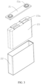
- FIG. 3 is a schematic structural exploded view of a battery cell 20 in a battery 100 according to some embodiments of this application.
- the battery cell 20 is a smallest unit constituting a battery.
- the battery cell 20 includes an end cover 21, a housing 22, an electrode assembly 23, and other functional components.
- the end cover 21 is a component that covers an opening of the housing 22 to isolate an internal environment of the battery cell 20 from an external environment.
- the shape of the end cover 21 may be adapted to the shape of the housing 22 to fit the housing 22.
- the end cover 21 may be made of a material with certain hardness and strength (for example, aluminum alloy), so that the end cover 21 is less likely to deform when subjected to extrusion and collision, allowing the battery cell 20 to have higher structural strength and enhanced safety performance.
- Functional components such as an electrode terminal 21a may be provided on the end cover 21.
- the electrode terminal 21a may be configured to be electrically connected to the electrode assembly 23 for outputting or inputting electric energy of the battery cell 20.
- the end cover 21 may be further provided with a pressure relief mechanism for releasing internal pressure when the internal pressure or temperature of the battery cell 20 reaches a threshold.
- the end cover 21 may also be made of various materials, such as copper, iron, aluminum, stainless steel, aluminum alloy, and plastic, which are not particularly limited in the embodiments of this application.
- an insulator may also be provided on an inner side of the end cover 21. The insulator may be configured to insulate an electrical connection component in the housing 22 from the end cover 21 to reduce the risk of short circuit.
- the insulator may be made of plastic, rubber, or the like.
- the housing 22 is an assembly configured to form an internal environment of the battery cell 20 by fitting with the end cover 21, where the formed internal environment may be used to accommodate the electrode assembly 23, an electrolyte, and other components.
- the housing 22 and the end cover 21 may be separate components, an opening may be provided on the housing 22, and the end cover 21 covers the opening to form the internal environment of the battery cell 20. Without limitation, the end cover 21 and the housing 22 may alternatively be integrated.
- the housing 22 may be of various shapes and sizes, such as a cuboid shape, a cylindrical shape, and a hexagonal prism shape. Specifically, the shape of the housing 22 may be determined according to a specific shape and size of the electrode assembly 23.
- the housing 22 may be made of various materials, such as copper, iron, aluminum, stainless steel, aluminum alloy, and plastic, which are not particularly limited in the embodiments of this application.
- the electrode assembly 23 is a component in which electrochemical reactions take place in the battery cell 20.
- the housing 22 may include one or more electrode assemblies 23.
- the electrode assembly 23 is mainly formed by winding or stacking a positive electrode plate and a negative electrode plate, and a separator is generally provided between the positive electrode plate and the negative electrode plate.
- Parts of the positive electrode plate and the negative electrode plate with active substances constitute a body portion of the electrode assembly, while parts of the positive electrode plate and the negative electrode plate without active substances separately constitute a tab 23a.
- a positive tab and a negative tab may both be located at one end of the body portion or be located at two ends of the body portion respectively.
- FIG. 4 shows a structure of a connecting component 500 according to an embodiment of this application.
- the connecting component 500 is configured to connect an electrode terminal and electrode assembly of a battery cell.
- the connecting component 500 is provided with a stress release structure 510, and the stress release structure 510 is configured to release stress at a weld between the connecting component 500 and the electrode terminal.
- the connecting component 500 may be a sheet-shaped structure as shown in the figure, so as to reduce the space occupied and increase energy density inside the battery cell.
- the connecting component 500 is generally made of a metal material with good electrical conductivity, so as to ensure stability of current transfer between the electrode assembly and the electrode terminal. It can be understood that the connecting component 500 may alternatively be a curved sheet-shaped structure or block-shaped structure, which is not limited herein.
- the stress release structure 510 may be, for example, a groove or an annular wavy structure. During welding, the stress release structure 510 provides a space for the connecting component 500 to contract inward to deform, so as to release the welding stress, thereby ensuring stability and reliability of the welding structure between the connecting component 500 and the electrode terminal.
- the stress release structure 510 is provided on the connecting component 500, such that when the connecting component 500 is welded to the electrode terminal, a welding region on the connecting component 500 can smoothly contract inward to deform during welding, so as to release the welding stress, thereby ensuring the stability of the welding structure between the connecting component 500 and the electrode terminal, preventing stress cracks or detachment from occurring after the connecting component 500 is welded to the electrode terminal which otherwise affects quality of the battery cell.
- the connecting component 500 includes a first connecting portion 520 configured to be connected to the electrode terminal and a second connecting portion 530 configured to be connected to the electrode assembly, and the stress release structure 510 is disposed on the first connecting portion 520.
- first connecting portion 520 and the second connecting portion 530 may be an integrally formed structure, so as to ensure the stability of current transfer.
- first connecting portion 520 and the second connecting portion 530 may alternatively be two portions fixedly connected to each other, so as to facilitate mold making and production.
- a boss may be provided on the first connecting portion 520 for optimizing the welding structure and determining the welding region. Welding a top wall of the boss to the electrode terminal can ensure not only the stability of the structure after welding but also the accuracy of the positioning of the welding region, avoiding welding position offset.
- the second connecting portion 530 is configured to be connected to a tab on the internal electrode assembly, so as to form a current channel between the electrode assembly and the electrode terminal.
- the connecting component 500 is arranged as the first connecting portion 520 and the second connecting portion 530 to achieve connections of the connecting component 500 with the electrode terminal and the electrode assembly, and the stress release structure 510 is disposed on the first connecting portion 520 to ensure the stability of the welding structure between the first connecting portion 520 and the electrode terminal.
- FIG. 5 shows a structure of the connecting component 500 from the bottom perspective according to an embodiment of this application.
- the stress release structure 510 includes a groove 511.
- the groove 511 may be provided on a top surface of the first connecting portion 520 as shown in FIG. 4 , or on a bottom surface of the first connecting portion 520 as shown in FIG. 5 , or certainly on both a top surface and bottom surface of the first connecting portion 520, such that the welding region on the first connecting portion 520 can smoothly contract into the groove during welding, so as to release the stress generated during welding via the groove 511.
- the groove 511 provided allows the welding region on the first connecting portion 520 to smoothly contract into the groove during welding when the first connecting portion 520 is welded to the electrode terminal, so as to release the welding stress, thereby ensuring the stability of the welding structure between the first connecting portion 520 and the electrode terminal.
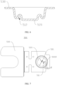
- FIG. 6 shows a cross-sectional structure of an annular wavy structure 512 in the connecting component 500 according to another embodiment of this application.
- the stress release structure 510 further includes the annular wavy structure 512.
- the annular wavy structure 512 when the first connecting portion 520 is welded to the electrode terminal, the annular wavy structure 512 deforms inward accordingly under the inward contraction force of the welding region on the first connecting portion 520, such that the welding region on the first connecting portion 520 can smoothly contract inward, ensuring the stability of the welding structure between the first connecting portion 520 and the electrode terminal.
- the groove 511 is provided in plurality and is strip-shaped.
- the groove 511 may be provided in three, and the three grooves 511 all extend from the center of the welding region toward the edge. It can be understood that in some other embodiments, the groove 511 may alternatively be provided in two or more, and the groove 511 may be a strip-shaped straight line, curve, or ring, provided that the welding stress can be released. The specific quantity and shape of the groove 511 are not limited herein.
- the groove 511 is provided in plurality and is strip-shaped, such that the groove 511 can cover the welding region on the first connecting portion 520 more comprehensively, and the stress generated in the welding region during welding can be more sufficiently released via the plurality of strip-shaped grooves 511, thereby further improving the stability of the welding structure.
- the plurality of grooves 511 communicate with each other.
- the plurality of grooves 511 may intersect and communicate at one end as shown in FIG. 5 , or certainly may cross and communicate with each other.
- the plurality of grooves 511 communicate with each other, such that the plurality of grooves 511 divide the welding region on the first connecting portion 520 into a plurality of portions, and in turn when the welding region contracts inward during welding, the plurality of portions under the contraction force can deform and get close to each other at the grooves 511, so as to further release the welding stress, thereby ensuring the stability of the welding structure between the first connecting portion 520 and the electrode terminal.
- FIG. 7 shows a top structure of the connecting component 500 according to an embodiment of this application.
- the plurality of grooves 511 have one end intersecting at the center of the first connecting portion 520.
- the plurality of grooves 511 have one end intersecting at the center of the first connecting portion 520, such that the welding stress causing contraction of the welding region on the first connecting portion 520 and concentrating at the center can be sufficiently released, so as to ensure the stability of the welding structure.
- the first connecting portion 520 is provided with a through hole 521 at the intersection.
- the first connecting portion 520 is provided with the through hole 521 at the intersection, such that the metal shavings generated during processing of the grooves 511 fall out of the through hole 521, thereby preventing the metal shavings from falling and accumulating in the grooves 511 which otherwise affects the subsequent welding.
- the first connecting portion 520 is provided with the through hole 521 at the intersection, such that the first connecting portion 520 can smoothly contract inward at the through hole 521 to deform during welding, thereby smoothly releasing the welding stress concentrating at the center via the through hole 521.
- FIG. 8 shows a cross-sectional structure of the connecting component 500 at the groove 511 according to an embodiment of this application.
- a ratio of depth of the groove 511 to thickness of the first connecting portion 520 is greater than or equal to 0.7.
- the depth of the groove 511 is h1 and the thickness of the first connecting portion 520 is h2, where h1/h2 ⁇ 0.7.
- the ratio of the depth of the groove 511 to the thickness of the first connecting portion 520 being set to be greater than or equal to 0.7 facilitates smooth deformation and contraction of the first connecting portion 520 at the groove 511 during welding, so as to further release the welding stress at the groove 511, thereby ensuring the stability and reliability of the welding structure between the first connecting portion 520 and the electrode terminal.
- width of the groove 511 is w, where 0 mm ⁇ w ⁇ 0.3 mm.
- Provision of the groove 511 on the first connecting portion 520 reduces structural strength of the first connecting portion 520.
- the inventor of this application has learned through tests and measurements that the width w of the groove 511 being set within the range of greater than 0 mm and less than or equal to 0.3 mm can not only ensure reliable structural strength of the first connecting portion 520 but also achieve effective release of the welding stress when the first connecting portion 520 is welded to the electrode terminal.
- the width w of the groove 511 is excessively large, when the welding track reaches the groove 511, the bottom wall of the groove 511 is penetrated by excessive welding due to the thin bottom wall of the groove 511, such that the electrode terminal is easily welded through due to excessively large melting depth during welding.
- the cross section of the groove 511 may be the rectangle shown in the figure. In some other embodiments, the cross section of the groove 511 may alternatively be set as an inverted triangle, a U shape, or the like. The specific shape of the cross section of the groove 511 is not limited herein.
- FIG. 9 shows a cross-sectional structure of the connecting component 500 at the groove 511 according to another embodiment of this application.
- the groove 511 runs through the first connecting portion 520.
- the first connecting portion 520 In the process of welding the first connecting portion 520 to the electrode terminal, because the groove 511 runs through the first connecting portion 520, the first connecting portion 520 forms a free end at an inner wall of the groove 511, and in turn the first connecting portion 520 around the groove 511 can quickly and smoothly contract into the groove 511 to deform during welding, resulting in accordingly decreased width of the groove 511, thereby quickly and effectively releasing the welding stress.
- a molten pool generated during welding can be stably fused with a side wall of the groove 511 and an outer wall of the electrode terminal during subsequent curing after entering the groove 511, so as to sufficiently improve the stability of the welding structure between the first connecting portion 520 and the electrode terminal.
- the second connecting portion 530 is sheet-shaped, and the first connecting portion 520 includes a protrusion 522 provided on a side of the second connecting portion 530, where the protrusion 522 is configured to be connected to the electrode terminal, the second connecting portion 530 and the first connecting portion 520 are an integral structure, a recess 523 is formed on a side of the second connecting portion 530 away from the first connecting portion 520 by forming the protrusion 522, the protrusion 522 includes a top wall 5221 and a side wall 5222, the side wall 5222 connects the top wall 5221 and the second connecting portion 530, and the stress release structure 510 is disposed on the top wall 5221.
- the first connecting portion 520 first abuts against the electrode terminal, then a portion of the structure of the first connecting portion 520 is welded through and melted, and the melted structure is fused with the electrode terminal during curing, so as to achieve fixed connection between the first connecting portion 520 and the electrode terminal.
- the first connecting portion 520 being arranged as the protrusion 522 helps to align and abut the welding regions on the first connecting portion 520 and the electrode terminal during welding. Because the top wall 5221 of the protrusion 522 is the welding region, the welding position on the connecting component 500 can be quickly determined.
- the welding track is easily controlled within the recess 523, thereby avoiding damage to structures outside the welding region due to inability to accurately determine the boundary of the welding region.
- the recess 523 being formed on the side of the second connecting portion 530 away from the first connecting portion 520 and corresponding to the protrusion 522 can ensure the thickness at the top wall 5221, thereby ensuring that the connecting component 500 can be fixed to the electrode terminal through welding.
- FIG. 10 shows a cross-sectional structure of the connecting component 500 assembled in the battery cell according to an embodiment of this application.
- the end cover 21 is provided with an electrode lead-out hole 211
- the electrode terminal 21a covers the electrode lead-out hole 211
- the protrusion 552 of the connecting component 500 extends into the electrode lead-out hole 211 to be electrically connected to the electrode terminal 21a.
- a sealing ring 24 is provided between the electrode terminal 21a and the end cover 21, and a portion of the sealing ring 24 extends into the electrode lead-out hole 211 to enclose a hole wall of the electrode lead-out hole 211.
- the stress release structure 510 and the side wall 5222 are apart from each other.
- a distance between an edge of the stress release structure 510 (that is, an end portion of an outer end of the groove 511 in FIG. 7 ) and the side wall 5222 is d, where d ⁇ 0, such that the stress release structure 510 and the side wall 5222 are apart from each other.
- the stress release structure 510 and the side wall 5222 are apart from each other, so as to prevent welding plasma from reaching the side wall 5222 via the stress release structure 510 which otherwise causes burns or scalds to an insulating material around the side wall 5222.
- FIG. 11 shows an exploded structure of a battery cell 20 according to an embodiment of this application.
- the battery cell 20 includes an electrode terminal 21a, an electrode assembly 23, and the connecting component 500 according to any one of the foregoing embodiments, where the connecting component 500 connects the electrode terminal 21a and the electrode assembly 23.
- a region provided with a stress release structure 510 at the top of the connecting component 500 is welded to the bottom of the electrode terminal 21a, and another region of the connecting component 500 is connected to the electrode assembly 23, so as to achieve current transfer between the electrode terminal 21a and the electrode assembly 23.
- the stress release structure 510 is provided on the connecting component 500, such that when the connecting component 500 is welded to the electrode terminal 21a during assembly of the battery cell 20, welding stress generated on the connecting component 500 can be released at the stress release structure 510, thereby ensuring stability of the welding structure between the connecting component 500 and the electrode terminal, preventing stress cracks or detachment from occurring after the connecting component 500 is welded to the electrode terminal which otherwise affects quality of the battery cell.
- the connecting component 500 may be welded to the electrode terminal 21a in a spiral track as shown in FIG. 12a , and after welding, the connecting component 500 smoothly contracts inward through the stress release structure, so as to release the generated welding stress.
- the connecting component 500 may alternatively be welded to the electrode terminal 21a in a plurality of concentric annular tracks as shown in FIG. 12b or in a single annular track as shown in FIG. 12c .
- a battery is further provided, including the battery cell according to the foregoing embodiment.
- the battery disclosed in the embodiments of this application may be used without limitation in electric apparatuses such as vehicles, ships, or aircrafts.
- an electric apparatus including the battery cell according to the foregoing embodiment.
- An embodiment of this application provides an electric apparatus that uses a battery cell as a power source.
- the electric apparatus may be but is not limited to a mobile phone, a tablet, a notebook computer, an electric toy, an electric tool, an electric bicycle, an electric vehicle, a ship, or a spacecraft.
- the electric toy may include a fixed or mobile electric toy, for example, a game console, an electric toy car, an electric toy ship, and an electric toy airplane.
- the spacecraft may include an airplane, a rocket, a space shuttle, a spaceship, and the like.
Landscapes
- Chemical & Material Sciences (AREA)
- Chemical Kinetics & Catalysis (AREA)
- Electrochemistry (AREA)
- General Chemical & Material Sciences (AREA)
- Engineering & Computer Science (AREA)
- Manufacturing & Machinery (AREA)
- Connection Of Batteries Or Terminals (AREA)
Abstract
Description
- This application claims priority to
Chinese Patent Application No. 202220075729.5, filed on January 12, 2022 - This application relates to the field of new energy technologies and specifically to a connecting component, a battery cell, a battery, and an electric apparatus.
- In a battery cell, an electrode assembly inside a housing is typically connected to an electrode terminal on an end cover through a connecting component, so as to transfer internal current to the electrode terminal. To ensure the stability of connection and conductivity between the connecting component and the electrode terminal, the connecting component is typically fixedly connected to the electrode terminal through welding, but detachment occurs between the connecting component and the electrode terminal after welding.
- In view of the foregoing problem, this application provides a connecting component, a battery cell, a battery, and an electric apparatus, so as to solve the problems of cracking and detachment in a welding structure between the connecting component and an electrode terminal, improving stability of welding.
- According to an aspect of this application, a connecting component is provided. The connecting component is configured to connect an electrode terminal and electrode assembly of a battery cell, where the connecting component is provided with a stress release structure, and the stress release structure is configured to release stress at a weld between the connecting component and the electrode terminal.
- In some embodiments, the connecting component includes a first connecting portion configured to be connected to the electrode terminal and a second connecting portion configured to be connected to the electrode assembly, and the stress release structure is disposed on the first connecting portion. The connecting component is arranged as the first connecting portion and the second connecting portion to achieve connections of the connecting component with the electrode terminal and the electrode assembly, and the stress release structure is disposed on the first connecting portion to ensure stability of the welding structure between the first connecting portion and the electrode terminal.
- In some embodiments, the stress release structure includes a groove. The groove provided allows a welding region on the first connecting portion to smoothly contract into the groove during welding when the first connecting portion is welded to the electrode terminal, so as to release the welding stress, thereby ensuring the stability of the welding structure between the first connecting portion and the electrode terminal.
- In some embodiments, the groove is provided in plurality and is strip-shaped. The groove is provided in plurality and is strip-shaped, such that the groove can cover the welding region on the first connecting portion more comprehensively, and the stress generated in the welding region during welding can be more sufficiently released via the plurality of strip-shaped grooves, thereby further improving the stability of the welding structure.
- In some embodiments, the plurality of grooves communicate with each other. The plurality of grooves communicate with each other, such that the plurality of grooves divide the welding region on the first connecting portion into a plurality of portions, and in turn when the welding region contracts inward during welding, the plurality of portions under the contraction force can deform and get close to each other at the grooves, so as to further release the welding stress, thereby ensuring the stability of the welding structure between the first connecting portion and the electrode terminal.
- In some embodiments, the plurality of grooves have one end intersecting at the center of the first connecting portion. For welding in a spiral or annular shape from the outer ring to the outer ring, more welding stress concentrates at the center of the first connecting portion. The plurality of grooves have one end intersecting at the center of the first connecting portion, such that the welding stress causing contraction of the welding region on the first connecting portion and concentrating at the center can be sufficiently released, so as to ensure the stability of the welding structure.
- In some embodiments, the first connecting portion is provided with a through hole at the intersection. The first connecting portion is provided with the through hole at the intersection, such that metal shavings generated during processing of the grooves fall out of the through hole, thereby preventing the metal shavings from falling and accumulating in the grooves which otherwise affects subsequent welding. In addition, the first connecting portion is provided with the through hole at the intersection, such that the first connecting portion can smoothly contract inward at the through hole to deform during welding, thereby smoothly releasing the welding stress concentrating at the center via the through hole.
- In some embodiments, a ratio of depth of the groove to thickness of the first connecting portion is greater than or equal to 0.7. The ratio of the depth of the groove to the thickness of the first connecting portion being set to be greater than or equal to 0.7 facilitates smooth deformation and contraction of the first connecting portion at the groove during welding, so as to further release the welding stress at the groove, thereby ensuring the stability and reliability of the welding structure between the first connecting portion and the electrode terminal.
- In some embodiments, width of the groove is w, where 0 mm < w ≤ 0.3 mm. The width w of the groove being set within the range of greater than 0 mm and less than or equal to 0.3 mm can not only ensure reliable structural strength of the first connecting portion but also achieve effective release of the welding stress when the first connecting portion is welded to the electrode terminal.
- In some embodiments, the groove runs through the first connecting portion. In the process of welding the first connecting portion to the electrode terminal, because the groove runs through the first connecting portion, the first connecting portion forms a free end at an inner wall of the groove, and in turn the first connecting portion around the groove can quickly and smoothly contract into the groove to deform during welding, resulting in accordingly decreased width of the groove, thereby quickly and effectively releasing the welding stress. In addition, with the groove running through the first connecting portion, a molten pool generated during welding can be stably fused with a side wall of the groove and an outer wall of the electrode terminal during subsequent curing after entering the groove, so as to sufficiently improve the stability of the welding structure between the first connecting portion and the electrode terminal.
- In some embodiments, the second connecting portion is sheet-shaped, and the first connecting portion includes a protrusion provided on a side of the second connecting portion, where the protrusion is configured to be connected to the electrode terminal, the second connecting portion and the first connecting portion are an integral structure, a recess is formed on a side of the second connecting portion away from the first connecting portion by forming the protrusion, the protrusion includes a top wall and a side wall, the side wall connects the top wall and the second connecting portion, and the stress release structure is disposed on the top wall. The first connecting portion being arranged as the protrusion helps to align and abut the welding regions on the first connecting portion and the electrode terminal during welding. Because the top wall of the protrusion is the welding region, the welding position on the connecting component can be quickly determined. With the recess formed on the side of the second connecting portion away from the first connecting portion, the welding track is easily controlled within the recess, thereby avoiding damage to structures outside the welding region due to inability to accurately determine the boundary of the welding region. In addition, if thickness of the welding region on the connecting component is excessively large, it is possible that the welding region cannot be welded through, resulting in welding failure. Therefore, the recess being formed on the side of the second connecting portion away from the first connecting portion and corresponding to the protrusion can ensure the thickness at the top wall, thereby ensuring that the connecting component can be fixed to the electrode terminal through welding.
- In some embodiments, the stress release structure and the side wall are apart from each other. In the battery cell, the stress release structure and the side wall are apart from each other, so as to prevent welding plasma from reaching the side wall via the stress release structure which otherwise causes burns or scalds to an insulating material around the side wall.
- According to another aspect of this application, a battery cell is provided, including an electrode terminal, an electrode assembly, and the connecting component according to any one of the foregoing embodiments, where the connecting component connects the electrode terminal and the electrode assembly. A stress release structure is provided on the connecting component, such that when the connecting component is welded to the electrode terminal during assembly of the battery cell, welding stress generated on the connecting component can be released at the stress release structure, thereby ensuring stability of the welding structure between the connecting component and the electrode terminal, preventing stress cracks or detachment from occurring after the connecting component is welded to the electrode terminal which otherwise affects quality of the battery cell.
- According to another aspect of this application, a battery is provided, including a plurality of battery cells as described above.
- According to another aspect of this application, an electric apparatus is provided, including a plurality of battery cells as described above.
- The foregoing description is merely an overview of the technical solution of this application. For a better understanding of the technical means in this application such that they can be implemented according to the content of the specification, and to make the above and other objectives, features, and advantages of this application more obvious and easier to understand, the following describes specific embodiments of this application.
- The stress release structure is provided on the connecting component, such that when the connecting component is welded to the electrode terminal, the welding region on the connecting component can smoothly contract inward to deform during welding, so as to release the welding stress, thereby ensuring the stability of the welding structure between the connecting component and the electrode terminal, preventing the stress cracks or detachment from occurring after the connecting component is welded to the electrode terminal which otherwise affects the quality of the battery cell.
- Persons of ordinary skill in the art can clearly understand various other advantages and benefits by reading the detailed description of the optional embodiments below. The accompanying drawings are merely intended to illustrate the optional embodiments and should not be construed as any limitation on this application. Throughout the accompanying drawings, the same reference signs represent the same components. In the accompanying drawings:
-
FIG. 1 is a schematic structural diagram of a vehicle according to an embodiment of this application; -
FIG. 2 is a schematic structural exploded view of a battery according to an embodiment of this application; -
FIG. 3 is a schematic structural exploded view of a battery cell according to an embodiment of this application; -
FIG. 4 is a schematic structural diagram of a connecting component from one perspective according to an embodiment of this application; -
FIG. 5 is a schematic structural diagram of a connecting component from another perspective according to an embodiment of this application; -
FIG. 6 is a schematic structural cross-sectional view of a connecting component at an annular wavy structure according to another embodiment of this application; -
FIG. 7 is a schematic structural top view of a connecting component according to an embodiment of this application; -
FIG. 8 is a schematic structural cross-sectional view of a connecting component at a groove according to an embodiment of this application; -
FIG. 9 is a schematic structural cross-sectional view of a connecting component at a groove according to another embodiment of this application; -
FIG. 10 is a schematic structural cross-sectional view of a connecting component assembled on a battery cell according to an embodiment of this application; -
FIG. 11 is a schematic structural exploded view of a battery cell according to another embodiment of this application; -
FIG. 12a is a schematic structural top view of a connecting component with a weld mark formed according to an embodiment of this application; -
FIG. 12b is a schematic structural top view of a connecting component with a weld mark formed according to another embodiment of this application; and -
FIG. 12c is a schematic structural top view of a connecting component with a weld mark formed according to still another embodiment of this application. - Reference signs in the specific embodiments are described as follows:
-
vehicle 1000; -
battery 100;controller 200;motor 300; -
box 10;first portion 11;second portion 12; -
battery cell 20;end cover 21; electrode lead-outhole 211;electrode terminal 21a;housing 22;electrode assembly 23;tab 23a; sealingring 24; - connecting
component 500;stress release structure 510; groove 511; annularwavy structure 512; first connectingportion 520; throughhole 521;protrusion 522;top wall 5221;side wall 5222;recess 523; and second connectingportion 530. - The following describes in detail the embodiments of technical solutions of this application with reference to the accompanying drawings. The following embodiments are merely used to describe the technical solutions in this application more clearly, and therefore are merely used as examples and do not constitute any limitation on the protection scope of this application.
- Unless otherwise defined, all technical and scientific terms used herein shall have the same meanings as commonly understood by persons skilled in the art to which this application belongs. The terms used herein are merely intended to describe the specific embodiments rather than to limit this application. The terms "include", "have", and any other variations thereof in the specification, claims, and brief description of drawings of this application are intended to cover non-exclusive inclusions.
- In the descriptions of the embodiments of this application, the technical terms "first", "second", and the like are merely intended to distinguish between different objects, and shall not be understood as any indication or implication of relative importance or any implicit indication of the number, specific sequence, or primary-secondary relationship of the technical features indicated. In the descriptions of the embodiments of this application, "a plurality of" means more than two, unless otherwise specifically defined.
- In this specification, reference to "embodiment" means that specific features, structures, or characteristics described with reference to the embodiment may be incorporated in at least one embodiment of this application. The word "embodiment" appearing in various places in this specification does not necessarily refer to the same embodiment or an independent or alternative embodiment that is exclusive of other embodiments. Persons skilled in the art explicitly and implicitly understand that the embodiments described herein may be combined with other embodiments.
- In the descriptions of the embodiments of this application, the term "and/or" is only an associative relationship for describing associated objects, indicating that three relationships may be present. For example, A and/or B may indicate the following three cases: presence of A, presence of both A and B, and presence of B. In addition, the character "/" in this specification generally indicates an "or" relationship between the contextually associated objects.
- In the descriptions of the embodiments of this application, the term "a plurality of" means more than two (inclusive). Similarly, "a plurality of groups" means more than two (inclusive) groups, and "a plurality of pieces" means more than two (inclusive) pieces.
- In the descriptions of the embodiments of this application, the orientations or positional relationships indicated by the technical terms "center", "longitudinal", "transverse", "length", "width", "thickness", "upper", "lower", "front", "rear", "left", "right", "vertical", "horizontal", "top", "bottom", "inside", "outside", "clockwise", "counterclockwise", "axial", "radial", "circumferential", and the like are based on the orientations or positional relationships shown in the accompanying drawings. These terms are merely for ease and brevity of the descriptions of the embodiments of this application rather than indicating or implying that the apparatuses or elements mentioned must have specific orientations or must be constructed or manipulated according to specific orientations, and therefore shall not be construed as any limitations on the embodiments of this application.
- In the descriptions of the embodiments of this application, unless otherwise specified and defined explicitly, the technical terms "mount", "connect", "join", and "fix" should be understood in their general senses. For example, they may refer to a fixed connection, a detachable connection, or an integral connection, may refer to a mechanical connection or an electrical connection, and may refer to a direct connection, an indirect connection via an intermediate medium, an internal communication between two elements, or an interaction between two elements. Persons of ordinary skill in the art can understand specific meanings of these terms in the embodiments of this application as appropriate to specific situations.
- Currently, from a perspective of the market development, batteries have been increasingly widely used. Batteries have been widely used in energy storage power supply systems such as hydroelectric power plants, thermal power plants, wind power plants, and solar power plants, and many other fields including electric transportation tools such as electric bicycles, electric motorcycles, and electric vehicles, military equipment, and aerospace. With continuous expansion of application fields of batteries, market demands for the batteries are also increasing.
- To improve the quality of battery cells so that the battery cells have a stable and reliable current channel, it is necessary to ensure that an electrode assembly and an electrode terminal in a battery cell have a good electrical connection structure.
- In an existing battery cell, the electrode assembly and the electrode terminal are connected to each other through a connecting component, so as to form an electrical connection structure. The connecting component is typically sheet-shaped, with one portion connected to the electrode assembly and the other portion connected to the electrode terminal. To ensure a stable connection structure between the connecting component and the electrode terminal, the connecting component is typically connected to the electrode terminal through welding to form a current channel.
- During welding, welding stress is generated due to contraction at a weld j oint. Specifically, internal stress caused by welding in the welded workpiece is referred to as welding stress. Based on the period when the welding stress is generated, the welding stress can be categorized into transient welding stress and residual welding stress. The transient welding stress is stress that varies with temperature during welding; and the residual welding stress is stress that remains after the welded workpiece cools to the initial temperature. Based on the orientation of the welding stress in the welded workpiece, the welding stress can be categorized into longitudinal stress, transverse stress, and thickness stress. Actually, the welding stress is three-dimensional stress. However, for a thin plate, the thickness stress is relatively small and therefore can be treated as two-dimensional stress.
- The inventor of this application has noticed that detachment occurs between the connecting component and the electrode terminal after the connecting component is welded to the electrode terminal. It is found through research that because a large welding stress is generated when the connecting component is welded to the electrode terminal, stress cracks easily occur at the weld between the connecting component and the electrode terminal. When the welding stress is excessively large, detachment may occur between the connecting component and the electrode terminal, resulting in short circuit, preventing the normal operation of the battery cell.
- In view of this, this application proposes a connecting component. A stress release structure is provided on the connecting component, for example, a groove is provided in a welding region on the connecting component or an annular wavy structure is provided on the periphery of the welding region, such that when the connecting component is welded to the electrode terminal, the welding region on the connecting component can contract into the groove to deform during welding, so as to release the welding stress, or the annular wavy structure on the periphery of the welding region on the connecting component can deform to extend inward, so as to release the welding stress, thereby ensuring stability of the welding structure between the connecting component and the electrode terminal.
- The battery disclosed in the embodiments of this application may be used without limitation in electric apparatuses such as vehicles, ships, or aircrafts.
- An embodiment of this application provides an electric apparatus that uses a battery as a power source. The electric apparatus may be but is not limited to a mobile phone, a tablet, a notebook computer, an electric toy, an electric tool, an electric bicycle, an electric vehicle, a ship, or a spacecraft. The electric toy may include a fixed or mobile electric toy, for example, a game console, an electric toy car, an electric toy ship, and an electric toy airplane. The spacecraft may include an airplane, a rocket, a space shuttle, a spaceship, and the like.
- For ease of description, the electric apparatus of an embodiment of this application being a
vehicle 1000 is used as an example for description of the following embodiments. - Referring to
FIG. 1, FIG. 1 is a schematic structural diagram of avehicle 1000 according to some embodiments of this application. Thevehicle 1000 may be a fossil fuel vehicle, a natural gas vehicle, or a new energy vehicle. The new energy vehicle may be a battery electric vehicle, a hybrid electric vehicle, a range-extended electric vehicle, or the like. Thevehicle 1000 is provided with abattery 100 inside, where thebattery 100 may be disposed at the bottom, front, or rear of thevehicle 1000. Thebattery 100 may be configured to supply power to thevehicle 1000. For example, thebattery 100 may be used as an operational power source for thevehicle 1000. Thevehicle 1000 may further include acontroller 200 and amotor 300, where thecontroller 200 is configured to control thebattery 100 to supply power to themotor 300, for example, to satisfy power needs of start, navigation, and driving of thevehicle 1000. - In some embodiments of this application, the
battery 100 can be used as not only the operational power source for thevehicle 1000 but also a driving power source for thevehicle 1000, replacing or partially replacing fossil fuel or natural gas to provide driving traction for thevehicle 1000. - Referring to
FIG. 2, FIG. 2 is a schematic structural exploded view of abattery 100 according to some embodiments of this application. Thebattery 100 includes abox 10 and abattery cell 20, where thebattery cell 20 is accommodated in thebox 10. Thebox 10 is configured to provide an accommodating space for thebattery cell 20. Thebox 10 may be a variety of structures. In some embodiments, thebox 10 may include afirst portion 11 and asecond portion 12. Thefirst portion 11 and thesecond portion 12 fit together to jointly define an accommodating space for accommodating thebattery cell 20. Thesecond portion 12 may be a hollow structure with an opening at one end, thefirst portion 11 may be a plate-shaped structure, and thefirst portion 11 covers the opening side of thesecond portion 12 so that thefirst portion 11 and thesecond portion 12 jointly define the accommodating space. Alternatively, both thefirst portion 11 and thesecond portion 12 may be hollow structures with an opening at one side, and the opening side of thefirst portion 11 is engaged with the opening side of thesecond portion 12. Certainly, thebox 10 formed by thefirst portion 11 and thesecond portion 12 may be of various shapes, for example, cylinder or cuboid. - In the
battery 100, thebattery cell 20 may be provided in plurality, and the plurality ofbattery cells 20 may be connected in series, parallel, or series-parallel, where being connected in series-parallel means a combination of series and parallel connections of the plurality ofbattery cells 20. The plurality ofbattery cells 20 may be directly connected in series, parallel, or series-parallel, and then an entirety of the plurality ofbattery cells 20 is accommodated in thebox 10; or certainly, thebattery 100 may be formed by a plurality ofbattery cells 20 being connected in series, parallel, or series-parallel first to form a battery module and then a plurality of battery modules being connected in series, parallel, or series-parallel to form an entirety which is accommodated in thebox 10. Thebattery 100 may further include other structures. For example, thebattery 100 may further include a busbar configured to implement electrical connection between the plurality ofbattery cells 20. - Each
battery cell 20 may be a secondary battery or a primary battery, and may be a lithiumsulfur battery, a sodium-ion battery, or a magnesium-ion battery, without being limited thereto. Thebattery cell 20 may be cylindrical, flat, cuboid, or of other shapes. - Referring to
FIG. 3, FIG. 3 is a schematic structural exploded view of abattery cell 20 in abattery 100 according to some embodiments of this application. Thebattery cell 20 is a smallest unit constituting a battery. As shown inFIG. 3 , thebattery cell 20 includes anend cover 21, ahousing 22, anelectrode assembly 23, and other functional components. - The
end cover 21 is a component that covers an opening of thehousing 22 to isolate an internal environment of thebattery cell 20 from an external environment. Without limitation, the shape of theend cover 21 may be adapted to the shape of thehousing 22 to fit thehousing 22. Optionally, theend cover 21 may be made of a material with certain hardness and strength (for example, aluminum alloy), so that theend cover 21 is less likely to deform when subjected to extrusion and collision, allowing thebattery cell 20 to have higher structural strength and enhanced safety performance. Functional components such as anelectrode terminal 21a may be provided on theend cover 21. Theelectrode terminal 21a may be configured to be electrically connected to theelectrode assembly 23 for outputting or inputting electric energy of thebattery cell 20. In some embodiments, theend cover 21 may be further provided with a pressure relief mechanism for releasing internal pressure when the internal pressure or temperature of thebattery cell 20 reaches a threshold. Theend cover 21 may also be made of various materials, such as copper, iron, aluminum, stainless steel, aluminum alloy, and plastic, which are not particularly limited in the embodiments of this application. In some embodiments, an insulator may also be provided on an inner side of theend cover 21. The insulator may be configured to insulate an electrical connection component in thehousing 22 from theend cover 21 to reduce the risk of short circuit. For example, the insulator may be made of plastic, rubber, or the like. - The
housing 22 is an assembly configured to form an internal environment of thebattery cell 20 by fitting with theend cover 21, where the formed internal environment may be used to accommodate theelectrode assembly 23, an electrolyte, and other components. Thehousing 22 and theend cover 21 may be separate components, an opening may be provided on thehousing 22, and theend cover 21 covers the opening to form the internal environment of thebattery cell 20. Without limitation, theend cover 21 and thehousing 22 may alternatively be integrated. Thehousing 22 may be of various shapes and sizes, such as a cuboid shape, a cylindrical shape, and a hexagonal prism shape. Specifically, the shape of thehousing 22 may be determined according to a specific shape and size of theelectrode assembly 23. Thehousing 22 may be made of various materials, such as copper, iron, aluminum, stainless steel, aluminum alloy, and plastic, which are not particularly limited in the embodiments of this application. - The
electrode assembly 23 is a component in which electrochemical reactions take place in thebattery cell 20. Thehousing 22 may include one ormore electrode assemblies 23. Theelectrode assembly 23 is mainly formed by winding or stacking a positive electrode plate and a negative electrode plate, and a separator is generally provided between the positive electrode plate and the negative electrode plate. Parts of the positive electrode plate and the negative electrode plate with active substances constitute a body portion of the electrode assembly, while parts of the positive electrode plate and the negative electrode plate without active substances separately constitute atab 23a. A positive tab and a negative tab may both be located at one end of the body portion or be located at two ends of the body portion respectively. During charging and discharging of the battery, a positive electrode active substance and a negative electrode active substance react with the electrolyte, and thetabs 23a are connected to the electrode terminals to form a current loop. - According to an aspect of the embodiments of this application, a connecting component is provided. Specifically, referring to
FIG. 4, FIG. 4 shows a structure of a connectingcomponent 500 according to an embodiment of this application. The connectingcomponent 500 is configured to connect an electrode terminal and electrode assembly of a battery cell. The connectingcomponent 500 is provided with astress release structure 510, and thestress release structure 510 is configured to release stress at a weld between the connectingcomponent 500 and the electrode terminal. - The connecting
component 500 may be a sheet-shaped structure as shown in the figure, so as to reduce the space occupied and increase energy density inside the battery cell. The connectingcomponent 500 is generally made of a metal material with good electrical conductivity, so as to ensure stability of current transfer between the electrode assembly and the electrode terminal. It can be understood that the connectingcomponent 500 may alternatively be a curved sheet-shaped structure or block-shaped structure, which is not limited herein. - The
stress release structure 510 may be, for example, a groove or an annular wavy structure. During welding, thestress release structure 510 provides a space for the connectingcomponent 500 to contract inward to deform, so as to release the welding stress, thereby ensuring stability and reliability of the welding structure between the connectingcomponent 500 and the electrode terminal. - The
stress release structure 510 is provided on the connectingcomponent 500, such that when the connectingcomponent 500 is welded to the electrode terminal, a welding region on the connectingcomponent 500 can smoothly contract inward to deform during welding, so as to release the welding stress, thereby ensuring the stability of the welding structure between the connectingcomponent 500 and the electrode terminal, preventing stress cracks or detachment from occurring after the connectingcomponent 500 is welded to the electrode terminal which otherwise affects quality of the battery cell. - Still referring to
FIG. 4 , according to some embodiments of this application, the connectingcomponent 500 includes a first connectingportion 520 configured to be connected to the electrode terminal and a second connectingportion 530 configured to be connected to the electrode assembly, and thestress release structure 510 is disposed on the first connectingportion 520. - Specifically, the first connecting
portion 520 and the second connectingportion 530 may be an integrally formed structure, so as to ensure the stability of current transfer. Certainly, the first connectingportion 520 and the second connectingportion 530 may alternatively be two portions fixedly connected to each other, so as to facilitate mold making and production. - A boss may be provided on the first connecting
portion 520 for optimizing the welding structure and determining the welding region. Welding a top wall of the boss to the electrode terminal can ensure not only the stability of the structure after welding but also the accuracy of the positioning of the welding region, avoiding welding position offset. The second connectingportion 530 is configured to be connected to a tab on the internal electrode assembly, so as to form a current channel between the electrode assembly and the electrode terminal. - The connecting
component 500 is arranged as the first connectingportion 520 and the second connectingportion 530 to achieve connections of the connectingcomponent 500 with the electrode terminal and the electrode assembly, and thestress release structure 510 is disposed on the first connectingportion 520 to ensure the stability of the welding structure between the first connectingportion 520 and the electrode terminal. - Still referring to
FIG. 4 and with further reference toFIG. 5, FIG. 5 shows a structure of the connectingcomponent 500 from the bottom perspective according to an embodiment of this application. According to some embodiments of this application, thestress release structure 510 includes agroove 511. - Specifically, the
groove 511 may be provided on a top surface of the first connectingportion 520 as shown inFIG. 4 , or on a bottom surface of the first connectingportion 520 as shown inFIG. 5 , or certainly on both a top surface and bottom surface of the first connectingportion 520, such that the welding region on the first connectingportion 520 can smoothly contract into the groove during welding, so as to release the stress generated during welding via thegroove 511. - The
groove 511 provided allows the welding region on the first connectingportion 520 to smoothly contract into the groove during welding when the first connectingportion 520 is welded to the electrode terminal, so as to release the welding stress, thereby ensuring the stability of the welding structure between the first connectingportion 520 and the electrode terminal. - Referring to
FIG. 6, FIG. 6 shows a cross-sectional structure of an annularwavy structure 512 in the connectingcomponent 500 according to another embodiment of this application. According to some embodiments of this application, thestress release structure 510 further includes the annularwavy structure 512. - Similarly, with the annular
wavy structure 512 provided, when the first connectingportion 520 is welded to the electrode terminal, the annularwavy structure 512 deforms inward accordingly under the inward contraction force of the welding region on the first connectingportion 520, such that the welding region on the first connectingportion 520 can smoothly contract inward, ensuring the stability of the welding structure between the first connectingportion 520 and the electrode terminal. - Still referring to
FIG. 5 , according to some embodiments of this application, thegroove 511 is provided in plurality and is strip-shaped. - As shown in
FIG. 5 , thegroove 511 may be provided in three, and the threegrooves 511 all extend from the center of the welding region toward the edge. It can be understood that in some other embodiments, thegroove 511 may alternatively be provided in two or more, and thegroove 511 may be a strip-shaped straight line, curve, or ring, provided that the welding stress can be released. The specific quantity and shape of thegroove 511 are not limited herein. - The
groove 511 is provided in plurality and is strip-shaped, such that thegroove 511 can cover the welding region on the first connectingportion 520 more comprehensively, and the stress generated in the welding region during welding can be more sufficiently released via the plurality of strip-shapedgrooves 511, thereby further improving the stability of the welding structure. - Still referring to
FIG. 5 , according to some embodiments of this application, the plurality ofgrooves 511 communicate with each other. - Specifically, the plurality of
grooves 511 may intersect and communicate at one end as shown inFIG. 5 , or certainly may cross and communicate with each other. - The plurality of
grooves 511 communicate with each other, such that the plurality ofgrooves 511 divide the welding region on the first connectingportion 520 into a plurality of portions, and in turn when the welding region contracts inward during welding, the plurality of portions under the contraction force can deform and get close to each other at thegrooves 511, so as to further release the welding stress, thereby ensuring the stability of the welding structure between the first connectingportion 520 and the electrode terminal. - Referring to
FIG. 7, FIG. 7 shows a top structure of the connectingcomponent 500 according to an embodiment of this application. According to some embodiments of this application, the plurality ofgrooves 511 have one end intersecting at the center of the first connectingportion 520. - For welding in a spiral or annular shape from the outer ring to the outer ring, more welding stress concentrates at the center of the first connecting
portion 520. The plurality ofgrooves 511 have one end intersecting at the center of the first connectingportion 520, such that the welding stress causing contraction of the welding region on the first connectingportion 520 and concentrating at the center can be sufficiently released, so as to ensure the stability of the welding structure. - Further, still referring to
FIG. 7 , according to some embodiments of this application, the first connectingportion 520 is provided with a throughhole 521 at the intersection. - When the
grooves 511 intersecting at the center are being processed on the first connectingportion 520, if no throughhole 521 is provided, a later processedgroove 511 will cut off an end corner of an earlier processedgroove 511 to generate metal shavings when intersecting with the earlier processedgroove 511, and the metal shavings falling and accumulating in thegrooves 511 adversely affect subsequent welding, resulting in reduced stability of the welding structure. - Based on this, the first connecting
portion 520 is provided with the throughhole 521 at the intersection, such that the metal shavings generated during processing of thegrooves 511 fall out of the throughhole 521, thereby preventing the metal shavings from falling and accumulating in thegrooves 511 which otherwise affects the subsequent welding. In addition, the first connectingportion 520 is provided with the throughhole 521 at the intersection, such that the first connectingportion 520 can smoothly contract inward at the throughhole 521 to deform during welding, thereby smoothly releasing the welding stress concentrating at the center via the throughhole 521. - Referring to
FIG. 8, FIG. 8 shows a cross-sectional structure of the connectingcomponent 500 at thegroove 511 according to an embodiment of this application. According to some embodiments of this application, a ratio of depth of thegroove 511 to thickness of the first connectingportion 520 is greater than or equal to 0.7. - As shown in
FIG. 8 , the depth of thegroove 511 is h1 and the thickness of the first connectingportion 520 is h2, where h1/h2 ≥ 0.7. - The ratio of the depth of the
groove 511 to the thickness of the first connectingportion 520 being set to be greater than or equal to 0.7 facilitates smooth deformation and contraction of the first connectingportion 520 at thegroove 511 during welding, so as to further release the welding stress at thegroove 511, thereby ensuring the stability and reliability of the welding structure between the first connectingportion 520 and the electrode terminal. - Still referring to
FIG. 8 , according to some embodiments of this application, width of thegroove 511 is w, where 0 mm < w ≤ 0.3 mm. - Provision of the
groove 511 on the first connectingportion 520 reduces structural strength of the first connectingportion 520. To prevent a great impact on the structural strength of the first connectingportion 520 while releasing the welding stress, the inventor of this application has learned through tests and measurements that the width w of thegroove 511 being set within the range of greater than 0 mm and less than or equal to 0.3 mm can not only ensure reliable structural strength of the first connectingportion 520 but also achieve effective release of the welding stress when the first connectingportion 520 is welded to the electrode terminal. - If the width w of the
groove 511 is excessively large, when the welding track reaches thegroove 511, the bottom wall of thegroove 511 is penetrated by excessive welding due to the thin bottom wall of thegroove 511, such that the electrode terminal is easily welded through due to excessively large melting depth during welding. - As shown in
FIG. 8 , the cross section of thegroove 511 may be the rectangle shown in the figure. In some other embodiments, the cross section of thegroove 511 may alternatively be set as an inverted triangle, a U shape, or the like. The specific shape of the cross section of thegroove 511 is not limited herein. - Referring to
FIG. 9, FIG. 9 shows a cross-sectional structure of the connectingcomponent 500 at thegroove 511 according to another embodiment of this application. According to some embodiments of this application, thegroove 511 runs through the first connectingportion 520. - In the process of welding the first connecting
portion 520 to the electrode terminal, because thegroove 511 runs through the first connectingportion 520, the first connectingportion 520 forms a free end at an inner wall of thegroove 511, and in turn the first connectingportion 520 around thegroove 511 can quickly and smoothly contract into thegroove 511 to deform during welding, resulting in accordingly decreased width of thegroove 511, thereby quickly and effectively releasing the welding stress. In addition, with thegroove 511 running through the first connectingportion 520, a molten pool generated during welding can be stably fused with a side wall of thegroove 511 and an outer wall of the electrode terminal during subsequent curing after entering thegroove 511, so as to sufficiently improve the stability of the welding structure between the first connectingportion 520 and the electrode terminal. - Still referring to
FIG. 4 andFIG. 5 , the second connectingportion 530 is sheet-shaped, and the first connectingportion 520 includes aprotrusion 522 provided on a side of the second connectingportion 530, where theprotrusion 522 is configured to be connected to the electrode terminal, the second connectingportion 530 and the first connectingportion 520 are an integral structure, arecess 523 is formed on a side of the second connectingportion 530 away from the first connectingportion 520 by forming theprotrusion 522, theprotrusion 522 includes atop wall 5221 and aside wall 5222, theside wall 5222 connects thetop wall 5221 and the second connectingportion 530, and thestress release structure 510 is disposed on thetop wall 5221. - During welding, the first connecting
portion 520 first abuts against the electrode terminal, then a portion of the structure of the first connectingportion 520 is welded through and melted, and the melted structure is fused with the electrode terminal during curing, so as to achieve fixed connection between the first connectingportion 520 and the electrode terminal. - The first connecting
portion 520 being arranged as theprotrusion 522 helps to align and abut the welding regions on the first connectingportion 520 and the electrode terminal during welding. Because thetop wall 5221 of theprotrusion 522 is the welding region, the welding position on the connectingcomponent 500 can be quickly determined. - With the
recess 523 formed on the side of the second connectingportion 530 away from the first connectingportion 520, the welding track is easily controlled within therecess 523, thereby avoiding damage to structures outside the welding region due to inability to accurately determine the boundary of the welding region. In addition, if thickness of the welding region on the connectingcomponent 500 is excessively large, it is possible that the welding region cannot be welded through, resulting in welding failure. Therefore, therecess 523 being formed on the side of the second connectingportion 530 away from the first connectingportion 520 and corresponding to theprotrusion 522 can ensure the thickness at thetop wall 5221, thereby ensuring that the connectingcomponent 500 can be fixed to the electrode terminal through welding. - Referring to
FIG. 10, FIG. 10 shows a cross-sectional structure of the connectingcomponent 500 assembled in the battery cell according to an embodiment of this application. As shown in the figure, theend cover 21 is provided with an electrode lead-outhole 211, theelectrode terminal 21a covers the electrode lead-outhole 211, and the protrusion 552 of the connectingcomponent 500 extends into the electrode lead-outhole 211 to be electrically connected to theelectrode terminal 21a. A sealingring 24 is provided between theelectrode terminal 21a and theend cover 21, and a portion of the sealingring 24 extends into the electrode lead-outhole 211 to enclose a hole wall of the electrode lead-outhole 211. - Referring to
FIG. 4 andFIG. 7 , according to some embodiments of this application, thestress release structure 510 and theside wall 5222 are apart from each other. - Specifically, as shown in
FIG. 7 , a distance between an edge of the stress release structure 510 (that is, an end portion of an outer end of thegroove 511 inFIG. 7 ) and theside wall 5222 is d, where d ≥ 0, such that thestress release structure 510 and theside wall 5222 are apart from each other. - In the battery cell, the
stress release structure 510 and theside wall 5222 are apart from each other, so as to prevent welding plasma from reaching theside wall 5222 via thestress release structure 510 which otherwise causes burns or scalds to an insulating material around theside wall 5222. - According to another aspect of the embodiments of this application, a battery cell is provided. Specifically, referring to
FIG. 11, FIG. 11 shows an exploded structure of abattery cell 20 according to an embodiment of this application. Thebattery cell 20 includes anelectrode terminal 21a, anelectrode assembly 23, and the connectingcomponent 500 according to any one of the foregoing embodiments, where the connectingcomponent 500 connects theelectrode terminal 21a and theelectrode assembly 23. - As shown in
FIG. 11 , a region provided with astress release structure 510 at the top of the connectingcomponent 500 is welded to the bottom of theelectrode terminal 21a, and another region of the connectingcomponent 500 is connected to theelectrode assembly 23, so as to achieve current transfer between theelectrode terminal 21a and theelectrode assembly 23. - The
stress release structure 510 is provided on the connectingcomponent 500, such that when the connectingcomponent 500 is welded to theelectrode terminal 21a during assembly of thebattery cell 20, welding stress generated on the connectingcomponent 500 can be released at thestress release structure 510, thereby ensuring stability of the welding structure between the connectingcomponent 500 and the electrode terminal, preventing stress cracks or detachment from occurring after the connectingcomponent 500 is welded to the electrode terminal which otherwise affects quality of the battery cell. - Specifically, the connecting
component 500 may be welded to theelectrode terminal 21a in a spiral track as shown inFIG. 12a , and after welding, the connectingcomponent 500 smoothly contracts inward through the stress release structure, so as to release the generated welding stress. The connectingcomponent 500 may alternatively be welded to theelectrode terminal 21a in a plurality of concentric annular tracks as shown inFIG. 12b or in a single annular track as shown inFIG. 12c . - According to another aspect of the embodiments of this application, a battery is further provided, including the battery cell according to the foregoing embodiment.
- The battery disclosed in the embodiments of this application may be used without limitation in electric apparatuses such as vehicles, ships, or aircrafts.
- According to another aspect of the embodiments of this application, an electric apparatus is further provided, including the battery cell according to the foregoing embodiment.
- An embodiment of this application provides an electric apparatus that uses a battery cell as a power source. The electric apparatus may be but is not limited to a mobile phone, a tablet, a notebook computer, an electric toy, an electric tool, an electric bicycle, an electric vehicle, a ship, or a spacecraft. The electric toy may include a fixed or mobile electric toy, for example, a game console, an electric toy car, an electric toy ship, and an electric toy airplane. The spacecraft may include an airplane, a rocket, a space shuttle, a spaceship, and the like.
- In conclusion, it should be noted that the foregoing embodiments are for description of the technical solutions of this application only rather than for limiting this application. Although this application has been described in detail with reference to the foregoing embodiments, persons of ordinary skill in the art should appreciate that they can still make modifications to the technical solutions described in the foregoing embodiments or make equivalent replacements to some or all technical features thereof without departing from the scope of the technical solutions of the embodiments of this application. All such modifications and equivalent replacements shall fall within the scope of the claims and specification of this application. In particular, as long as there is no structural conflict, the various technical features mentioned in the embodiments can be combined in any manner. This application is not limited to the specific embodiments disclosed in this specification but includes all technical solutions falling within the scope of the claims.
Claims (17)
- A connecting component, the connecting component being configured to connect an electrode terminal and electrode assembly of a battery cell, wherein the connecting component is provided with a stress release structure, and the stress release structure is configured to release stress at a weld between the connecting component and the electrode terminal.
- The connecting component according to claim 1, wherein the connecting component comprises a first connecting portion configured to be connected to the electrode terminal and a second connecting portion configured to be connected to the electrode assembly, and the stress release structure is disposed on the first connecting portion.
- The connecting component according to claim 2, wherein the stress release structure comprises a groove.
- The connecting component according to claim 3, wherein the groove is provided in plurality and is strip-shaped.
- The connecting component according to claim 4, wherein the plurality of grooves communicate with each other.
- The connecting component according to claim 5, wherein the plurality of grooves have one end intersecting at the center of the first connecting portion.
- The connecting component according to claim 6, wherein the first connecting portion is provided with a through hole at the intersection.
- The connecting component according to any one of claims 3 to 7, wherein the groove is provided on a top surface of the first connecting portion; or the groove is provided on a bottom surface of the first connecting portion; or the groove is provided on both a top surface and bottom surface of the first connecting portion.
- The connecting component according to any one of claims 3 to 8, wherein a ratio of depth of the groove to thickness of the first connecting portion is greater than or equal to 0.7.
- The connecting component according to any one of claims 3 to 9, wherein width of the groove is w, wherein 0 mm < w ≤ 0.3 mm.
- The connecting component according to any one of claims 3 to 10, wherein the groove runs through the first connecting portion.
- The connecting component according to any one of claims 2 to 11, wherein
the second connecting portion is sheet-shaped, and the first connecting portion comprises a protrusion provided on a side of the second connecting portion, wherein the protrusion is configured to be connected to the electrode terminal, the second connecting portion and the first connecting portion are an integral structure, a recess is formed on a side of the second connecting portion away from the first connecting portion by forming the protrusion, the protrusion comprises a top wall and a side wall, the side wall connects the top wall and the second connecting portion, and the stress release structure is disposed on the top wall. - The connecting component according to claim 12, wherein the stress release structure and the side wall are apart from each other.
- A battery cell, comprising an electrode terminal, an electrode assembly, and the connecting component according to any one of claims 1 to 13, wherein the connecting component connects the electrode terminal and the electrode assembly.
- The battery cell according to claim 14, wherein the connecting component is welded to the electrode terminal in a spiral track.
- A battery, comprising a plurality of battery cells according to claim 14 or 15.
- An electric apparatus, comprising a plurality of battery cells according to claim 14 or 15.
Applications Claiming Priority (2)
| Application Number | Priority Date | Filing Date | Title |
|---|---|---|---|
| CN202220075729.5U CN216903240U (en) | 2022-01-12 | 2022-01-12 | Connecting part, battery monomer, battery and power utilization device |
| PCT/CN2022/135566 WO2023134318A1 (en) | 2022-01-12 | 2022-11-30 | Connecting component, battery cell, battery and electric device |
Publications (2)
| Publication Number | Publication Date |
|---|---|
| EP4456308A1 true EP4456308A1 (en) | 2024-10-30 |
| EP4456308A4 EP4456308A4 (en) | 2025-08-13 |
Family
ID=82212427
Family Applications (1)
| Application Number | Title | Priority Date | Filing Date |
|---|---|---|---|
| EP22919951.8A Pending EP4456308A4 (en) | 2022-01-12 | 2022-11-30 | CONNECTION COMPONENT, BATTERY CELL, BATTERY AND ELECTRICAL DEVICE |
Country Status (4)
| Country | Link |
|---|---|
| US (1) | US20240363975A1 (en) |
| EP (1) | EP4456308A4 (en) |
| CN (1) | CN216903240U (en) |
| WO (1) | WO2023134318A1 (en) |
Families Citing this family (1)
| Publication number | Priority date | Publication date | Assignee | Title |
|---|---|---|---|---|
| CN216903240U (en) * | 2022-01-12 | 2022-07-05 | 宁德时代新能源科技股份有限公司 | Connecting part, battery monomer, battery and power utilization device |
Family Cites Families (6)
| Publication number | Priority date | Publication date | Assignee | Title |
|---|---|---|---|---|
| JP2017168340A (en) * | 2016-03-17 | 2017-09-21 | パナソニックIpマネジメント株式会社 | Welded structure, battery using the same, and method of manufacturing welded structure |
| CN208753420U (en) * | 2018-08-08 | 2019-04-16 | 深圳市瑞德丰精密制造有限公司 | A kind of battery pole ear conductive sheet |
| CN110000472A (en) * | 2019-02-26 | 2019-07-12 | 武汉力神动力电池系统科技有限公司 | A kind of method for laser welding of power battery module aluminium alloy end plate and side plate |
| CN210040374U (en) * | 2019-07-31 | 2020-02-07 | 宁德时代新能源科技股份有限公司 | Battery module |
| CN214043712U (en) * | 2020-12-10 | 2021-08-24 | 湖北亿纬动力有限公司 | Lithium battery current collecting disc and cylindrical lithium battery comprising same |
| CN216903240U (en) * | 2022-01-12 | 2022-07-05 | 宁德时代新能源科技股份有限公司 | Connecting part, battery monomer, battery and power utilization device |
-
2022
- 2022-01-12 CN CN202220075729.5U patent/CN216903240U/en active Active
- 2022-11-30 WO PCT/CN2022/135566 patent/WO2023134318A1/en not_active Ceased
- 2022-11-30 EP EP22919951.8A patent/EP4456308A4/en active Pending
-
2024
- 2024-07-04 US US18/764,176 patent/US20240363975A1/en active Pending
Also Published As
| Publication number | Publication date |
|---|---|
| WO2023134318A1 (en) | 2023-07-20 |
| EP4456308A4 (en) | 2025-08-13 |
| US20240363975A1 (en) | 2024-10-31 |
| CN216903240U (en) | 2022-07-05 |
Similar Documents
| Publication | Publication Date | Title |
|---|---|---|
| US20240304918A1 (en) | Box of battery, battery, electrical apparatus, and manufacturing device for batteries | |
| EP4395050A1 (en) | Battery cell, battery, and electric device | |
| US20240380039A1 (en) | Battery top cover, top cover assembly, battery cell, battery, and power consuming device | |
| EP4418427A1 (en) | Battery box body, battery and electrical device | |
| EP4550553A1 (en) | Bottom support plate, battery cell, battery pack, and electric device | |
| EP4462588A1 (en) | Battery cell top cover, battery cell, battery, electric device, and liquid injection nozzle | |
| US20230238642A1 (en) | Battery cell, battery, power consuming device, and method for manufacturing battery cell | |
| EP4407783A1 (en) | Safety structure, battery and electric device | |
| US20240313309A1 (en) | Battery top cover assembly, battery cell, battery, and electric apparatus | |
| US20240363975A1 (en) | Connecting component, battery cell, battery, and electric apparatus | |
| US20260142300A1 (en) | Method for manufacturing battery cell, battery cell, battery, and electric apparatus | |
| US20260074375A1 (en) | Battery cell, battery, and power consuming apparatus | |
| US12469926B2 (en) | Battery cell, cover assembly, battery, electric apparatus, method, and device | |
| US20250062457A1 (en) | End cover assembly, battery cell, battery, and electric apparatus | |
| KR102964990B1 (en) | Tab welded structure, battery cell, and electrical equipment | |
| US20250253498A1 (en) | Battery cell, battery, and electric apparatus | |
| US12249723B2 (en) | Battery, electric device, and method and device for preparing battery cell | |
| US20240006703A1 (en) | Battery, power consuming device and method for manufacturing battery | |
| EP4432454A1 (en) | Electrode sheet, electrode assembly, battery cell, battery, and electrical device | |
| WO2024055311A1 (en) | Battery cell, battery and electric device | |
| US20250096439A1 (en) | Battery cell, battery and electric device | |
| US20250309472A1 (en) | Battery cell, battery, and electrical device | |
| EP4510348A1 (en) | Battery cell, battery, and electrical apparatus | |
| EP4557494A1 (en) | Battery cell, battery and electrical apparatus | |
| EP4510322A1 (en) | End cover assembly, battery cell, battery, and electric device |
Legal Events
| Date | Code | Title | Description |
|---|---|---|---|
| STAA | Information on the status of an ep patent application or granted ep patent |
Free format text: STATUS: THE INTERNATIONAL PUBLICATION HAS BEEN MADE |
|
| PUAI | Public reference made under article 153(3) epc to a published international application that has entered the european phase |
Free format text: ORIGINAL CODE: 0009012 |
|
| STAA | Information on the status of an ep patent application or granted ep patent |
Free format text: STATUS: REQUEST FOR EXAMINATION WAS MADE |
|
| 17P | Request for examination filed |
Effective date: 20240723 |
|
| AK | Designated contracting states |
Kind code of ref document: A1 Designated state(s): AL AT BE BG CH CY CZ DE DK EE ES FI FR GB GR HR HU IE IS IT LI LT LU LV MC ME MK MT NL NO PL PT RO RS SE SI SK SM TR |
|
| DAV | Request for validation of the european patent (deleted) | ||
| DAX | Request for extension of the european patent (deleted) | ||
| A4 | Supplementary search report drawn up and despatched |
Effective date: 20250715 |
|
| RIC1 | Information provided on ipc code assigned before grant |
Ipc: H01M 50/50 20210101AFI20250709BHEP Ipc: H01M 50/543 20210101ALI20250709BHEP Ipc: H01M 50/566 20210101ALI20250709BHEP Ipc: H01M 50/209 20210101ALI20250709BHEP Ipc: H01M 50/516 20210101ALI20250709BHEP Ipc: H01M 50/553 20210101ALI20250709BHEP |