EP4456288A1 - Battery pack and energy storage system including same - Google Patents
Battery pack and energy storage system including same Download PDFInfo
- Publication number
- EP4456288A1 EP4456288A1 EP23767022.9A EP23767022A EP4456288A1 EP 4456288 A1 EP4456288 A1 EP 4456288A1 EP 23767022 A EP23767022 A EP 23767022A EP 4456288 A1 EP4456288 A1 EP 4456288A1
- Authority
- EP
- European Patent Office
- Prior art keywords
- cell assembly
- plate
- firefighting
- tank
- battery pack
- Prior art date
- Legal status (The legal status is an assumption and is not a legal conclusion. Google has not performed a legal analysis and makes no representation as to the accuracy of the status listed.)
- Pending
Links
Images





Classifications
-
- H—ELECTRICITY
- H01—ELECTRIC ELEMENTS
- H01M—PROCESSES OR MEANS, e.g. BATTERIES, FOR THE DIRECT CONVERSION OF CHEMICAL ENERGY INTO ELECTRICAL ENERGY
- H01M50/00—Constructional details or processes of manufacture of the non-active parts of electrochemical cells other than fuel cells, e.g. hybrid cells
- H01M50/20—Mountings; Secondary casings or frames; Racks, modules or packs; Suspension devices; Shock absorbers; Transport or carrying devices; Holders
- H01M50/204—Racks, modules or packs for multiple batteries or multiple cells
-
- H—ELECTRICITY
- H01—ELECTRIC ELEMENTS
- H01M—PROCESSES OR MEANS, e.g. BATTERIES, FOR THE DIRECT CONVERSION OF CHEMICAL ENERGY INTO ELECTRICAL ENERGY
- H01M10/00—Secondary cells; Manufacture thereof
- H01M10/05—Accumulators with non-aqueous electrolyte
- H01M10/052—Li-accumulators
-
- H—ELECTRICITY
- H01—ELECTRIC ELEMENTS
- H01M—PROCESSES OR MEANS, e.g. BATTERIES, FOR THE DIRECT CONVERSION OF CHEMICAL ENERGY INTO ELECTRICAL ENERGY
- H01M10/00—Secondary cells; Manufacture thereof
- H01M10/04—Construction or manufacture in general
- H01M10/0481—Compression means other than compression means for stacks of electrodes and separators
-
- H—ELECTRICITY
- H01—ELECTRIC ELEMENTS
- H01M—PROCESSES OR MEANS, e.g. BATTERIES, FOR THE DIRECT CONVERSION OF CHEMICAL ENERGY INTO ELECTRICAL ENERGY
- H01M10/00—Secondary cells; Manufacture thereof
- H01M10/42—Methods or arrangements for servicing or maintenance of secondary cells or secondary half-cells
-
- H—ELECTRICITY
- H01—ELECTRIC ELEMENTS
- H01M—PROCESSES OR MEANS, e.g. BATTERIES, FOR THE DIRECT CONVERSION OF CHEMICAL ENERGY INTO ELECTRICAL ENERGY
- H01M50/00—Constructional details or processes of manufacture of the non-active parts of electrochemical cells other than fuel cells, e.g. hybrid cells
- H01M50/20—Mountings; Secondary casings or frames; Racks, modules or packs; Suspension devices; Shock absorbers; Transport or carrying devices; Holders
- H01M50/204—Racks, modules or packs for multiple batteries or multiple cells
- H01M50/207—Racks, modules or packs for multiple batteries or multiple cells characterised by their shape
- H01M50/209—Racks, modules or packs for multiple batteries or multiple cells characterised by their shape adapted for prismatic or rectangular cells
-
- H—ELECTRICITY
- H01—ELECTRIC ELEMENTS
- H01M—PROCESSES OR MEANS, e.g. BATTERIES, FOR THE DIRECT CONVERSION OF CHEMICAL ENERGY INTO ELECTRICAL ENERGY
- H01M50/00—Constructional details or processes of manufacture of the non-active parts of electrochemical cells other than fuel cells, e.g. hybrid cells
- H01M50/20—Mountings; Secondary casings or frames; Racks, modules or packs; Suspension devices; Shock absorbers; Transport or carrying devices; Holders
- H01M50/204—Racks, modules or packs for multiple batteries or multiple cells
- H01M50/207—Racks, modules or packs for multiple batteries or multiple cells characterised by their shape
- H01M50/211—Racks, modules or packs for multiple batteries or multiple cells characterised by their shape adapted for pouch cells
-
- H—ELECTRICITY
- H01—ELECTRIC ELEMENTS
- H01M—PROCESSES OR MEANS, e.g. BATTERIES, FOR THE DIRECT CONVERSION OF CHEMICAL ENERGY INTO ELECTRICAL ENERGY
- H01M50/00—Constructional details or processes of manufacture of the non-active parts of electrochemical cells other than fuel cells, e.g. hybrid cells
- H01M50/20—Mountings; Secondary casings or frames; Racks, modules or packs; Suspension devices; Shock absorbers; Transport or carrying devices; Holders
- H01M50/233—Mountings; Secondary casings or frames; Racks, modules or packs; Suspension devices; Shock absorbers; Transport or carrying devices; Holders characterised by physical properties of casings or racks, e.g. dimensions
- H01M50/24—Mountings; Secondary casings or frames; Racks, modules or packs; Suspension devices; Shock absorbers; Transport or carrying devices; Holders characterised by physical properties of casings or racks, e.g. dimensions adapted for protecting batteries from their environment, e.g. from corrosion
-
- H—ELECTRICITY
- H01—ELECTRIC ELEMENTS
- H01M—PROCESSES OR MEANS, e.g. BATTERIES, FOR THE DIRECT CONVERSION OF CHEMICAL ENERGY INTO ELECTRICAL ENERGY
- H01M50/00—Constructional details or processes of manufacture of the non-active parts of electrochemical cells other than fuel cells, e.g. hybrid cells
- H01M50/20—Mountings; Secondary casings or frames; Racks, modules or packs; Suspension devices; Shock absorbers; Transport or carrying devices; Holders
- H01M50/233—Mountings; Secondary casings or frames; Racks, modules or packs; Suspension devices; Shock absorbers; Transport or carrying devices; Holders characterised by physical properties of casings or racks, e.g. dimensions
- H01M50/242—Mountings; Secondary casings or frames; Racks, modules or packs; Suspension devices; Shock absorbers; Transport or carrying devices; Holders characterised by physical properties of casings or racks, e.g. dimensions adapted for protecting batteries against vibrations, collision impact or swelling
-
- H—ELECTRICITY
- H01—ELECTRIC ELEMENTS
- H01M—PROCESSES OR MEANS, e.g. BATTERIES, FOR THE DIRECT CONVERSION OF CHEMICAL ENERGY INTO ELECTRICAL ENERGY
- H01M50/00—Constructional details or processes of manufacture of the non-active parts of electrochemical cells other than fuel cells, e.g. hybrid cells
- H01M50/20—Mountings; Secondary casings or frames; Racks, modules or packs; Suspension devices; Shock absorbers; Transport or carrying devices; Holders
- H01M50/251—Mountings; Secondary casings or frames; Racks, modules or packs; Suspension devices; Shock absorbers; Transport or carrying devices; Holders specially adapted for stationary devices, e.g. power plant buffering or backup power supplies
-
- H—ELECTRICITY
- H01—ELECTRIC ELEMENTS
- H01M—PROCESSES OR MEANS, e.g. BATTERIES, FOR THE DIRECT CONVERSION OF CHEMICAL ENERGY INTO ELECTRICAL ENERGY
- H01M50/00—Constructional details or processes of manufacture of the non-active parts of electrochemical cells other than fuel cells, e.g. hybrid cells
- H01M50/20—Mountings; Secondary casings or frames; Racks, modules or packs; Suspension devices; Shock absorbers; Transport or carrying devices; Holders
- H01M50/262—Mountings; Secondary casings or frames; Racks, modules or packs; Suspension devices; Shock absorbers; Transport or carrying devices; Holders with fastening means, e.g. locks
-
- H—ELECTRICITY
- H01—ELECTRIC ELEMENTS
- H01M—PROCESSES OR MEANS, e.g. BATTERIES, FOR THE DIRECT CONVERSION OF CHEMICAL ENERGY INTO ELECTRICAL ENERGY
- H01M50/00—Constructional details or processes of manufacture of the non-active parts of electrochemical cells other than fuel cells, e.g. hybrid cells
- H01M50/20—Mountings; Secondary casings or frames; Racks, modules or packs; Suspension devices; Shock absorbers; Transport or carrying devices; Holders
- H01M50/262—Mountings; Secondary casings or frames; Racks, modules or packs; Suspension devices; Shock absorbers; Transport or carrying devices; Holders with fastening means, e.g. locks
- H01M50/264—Mountings; Secondary casings or frames; Racks, modules or packs; Suspension devices; Shock absorbers; Transport or carrying devices; Holders with fastening means, e.g. locks for cells or batteries, e.g. straps, tie rods or peripheral frames
-
- H—ELECTRICITY
- H01—ELECTRIC ELEMENTS
- H01M—PROCESSES OR MEANS, e.g. BATTERIES, FOR THE DIRECT CONVERSION OF CHEMICAL ENERGY INTO ELECTRICAL ENERGY
- H01M50/00—Constructional details or processes of manufacture of the non-active parts of electrochemical cells other than fuel cells, e.g. hybrid cells
- H01M50/20—Mountings; Secondary casings or frames; Racks, modules or packs; Suspension devices; Shock absorbers; Transport or carrying devices; Holders
- H01M50/271—Lids or covers for the racks or secondary casings
-
- H—ELECTRICITY
- H01—ELECTRIC ELEMENTS
- H01M—PROCESSES OR MEANS, e.g. BATTERIES, FOR THE DIRECT CONVERSION OF CHEMICAL ENERGY INTO ELECTRICAL ENERGY
- H01M50/00—Constructional details or processes of manufacture of the non-active parts of electrochemical cells other than fuel cells, e.g. hybrid cells
- H01M50/30—Arrangements for facilitating escape of gases
- H01M50/383—Flame arresting or ignition-preventing means
-
- H—ELECTRICITY
- H01—ELECTRIC ELEMENTS
- H01M—PROCESSES OR MEANS, e.g. BATTERIES, FOR THE DIRECT CONVERSION OF CHEMICAL ENERGY INTO ELECTRICAL ENERGY
- H01M50/00—Constructional details or processes of manufacture of the non-active parts of electrochemical cells other than fuel cells, e.g. hybrid cells
- H01M50/60—Arrangements or processes for filling or topping-up with liquids; Arrangements or processes for draining liquids from casings
- H01M50/673—Containers for storing liquids; Delivery conduits therefor
-
- H—ELECTRICITY
- H01—ELECTRIC ELEMENTS
- H01M—PROCESSES OR MEANS, e.g. BATTERIES, FOR THE DIRECT CONVERSION OF CHEMICAL ENERGY INTO ELECTRICAL ENERGY
- H01M10/00—Secondary cells; Manufacture thereof
- H01M10/04—Construction or manufacture in general
- H01M10/0413—Large-sized flat cells or batteries for motive or stationary systems with plate-like electrodes
-
- H—ELECTRICITY
- H01—ELECTRIC ELEMENTS
- H01M—PROCESSES OR MEANS, e.g. BATTERIES, FOR THE DIRECT CONVERSION OF CHEMICAL ENERGY INTO ELECTRICAL ENERGY
- H01M2220/00—Batteries for particular applications
- H01M2220/10—Batteries in stationary systems, e.g. emergency power source in plant
-
- H—ELECTRICITY
- H01—ELECTRIC ELEMENTS
- H01M—PROCESSES OR MEANS, e.g. BATTERIES, FOR THE DIRECT CONVERSION OF CHEMICAL ENERGY INTO ELECTRICAL ENERGY
- H01M2220/00—Batteries for particular applications
- H01M2220/20—Batteries in motive systems, e.g. vehicle, ship, plane
-
- Y—GENERAL TAGGING OF NEW TECHNOLOGICAL DEVELOPMENTS; GENERAL TAGGING OF CROSS-SECTIONAL TECHNOLOGIES SPANNING OVER SEVERAL SECTIONS OF THE IPC; TECHNICAL SUBJECTS COVERED BY FORMER USPC CROSS-REFERENCE ART COLLECTIONS [XRACs] AND DIGESTS
- Y02—TECHNOLOGIES OR APPLICATIONS FOR MITIGATION OR ADAPTATION AGAINST CLIMATE CHANGE
- Y02E—REDUCTION OF GREENHOUSE GAS [GHG] EMISSIONS, RELATED TO ENERGY GENERATION, TRANSMISSION OR DISTRIBUTION
- Y02E60/00—Enabling technologies; Technologies with a potential or indirect contribution to GHG emissions mitigation
- Y02E60/10—Energy storage using batteries
Definitions
- the present disclosure relates to a battery pack and an energy storage system including the same, and more particularly, to a battery pack configured to ensure safety even when a thermal event occurs, and an energy storage system including the same.
- lithium secondary batteries have come into the spotlight because they have advantages, for example, hardly exhibiting memory effects in comparison with nickel-based secondary batteries and thus being freely charged and discharged, and having very low self-discharge rate and high energy density.
- the lithium secondary battery mainly uses lithium oxide and carbonaceous material as a cathode active material and an anode active material, respectively.
- the lithium secondary battery includes an electrode assembly in which a cathode plate and an anode plate respectively coated with the cathode active material and the anode active material are disposed with a separator interposed between them, and an exterior material which seals and receives the electrode assembly together with an electrolyte solution.
- a lithium secondary battery may be classified into a can-type secondary battery where the electrode assembly is mounted in a metal can, and a pouch-type battery where the electrode assembly is mounted in a pouch of an aluminum laminate.
- the can-type secondary battery may be further classified into a cylindrical battery and a prismatic battery.
- the pouch of the pouch-type secondary battery can be largely divided into a lower sheet and an upper sheet covering it.
- an electrode assembly formed by stacking and winding a cathode, an anode and a separator is housed in the pouch.
- the edges of the upper sheet and the lower sheet are sealed by heat sealing or the like.
- the electrode tab drawn out from each electrode may be coupled to the electrode lead, and an insulating film may be added to a portion wherein the electrode lead comes into contact with the sealing part.
- the pouch-type secondary battery can have the flexibility to be configured in various forms.
- the pouch-type secondary battery has the advantage that a secondary battery having the same capacity can be realized with a smaller volume and mass.
- the lithium secondary battery is made into a dense structure in which a plurality of battery cells are overlapped or stacked by themselves or in a state of being mounted in a cartridge or the like so as to provide high voltage and high current, and then is used as a cell module or a battery pack in which they are electrically connected.
- the energy storage system may also be composed of an assembly of home battery packs used in various types of houses (e.g., a detached house, an apartment, etc.).
- one of the typically important issues is safety.
- a thermal event occurs in one battery cell among a plurality of battery cells included in the battery pack, such an event need to be suppressed from propagating to other battery cells. If thermal propagation between battery cells is not properly suppressed, this causes a thermal event in several battery cells included in the battery pack, which may cause bigger problems such as ignition or explosion of the battery pack.
- the ignition or explosion that occurs in the battery pack may cause great damage to human life or loss of property in the periphery.
- a configuration capable of appropriately controlling the above-mentioned thermal event is required.
- the present disclosure has been designed to solve the above problems, and an object thereof is to provide a battery pack having an improved structure so as to properly control a thermal event which occurs inside the battery pack, and an energy storage system including the same.
- a battery pack comprising: a pack case, a cell module provided inside the pack case and including a cell assembly having a plurality of battery cells, a firefighting tank disposed on an upper side of the cell assembly and holding a fire extinguishing agent in an internal space, and an end plate disposed on at least one of the front and rear sides of the cell assembly and configured to support the firefighting tank.
- the end plates may be disposed on both sides at the front and rear of the cell assembly, and may be configured to press at least one of front and rear surfaces of the cell assembly when swelling of the battery cell occurs.
- the firefighting tank may be configured to discharge the fire extinguishing agent between both sides of the bottom part toward the cell assembly when heat is applied from the cell assembly, and the end plates may support both sides of the bottom part of the firefighting tank in a vertical direction.
- a fixing part having a predetermined area and making surface contact with both sides of the bottom part of the firefighting tank may be provided on the upper side of the end plate.
- the fixing part may be bent from an upper end of the end plate and formed to extend to a predetermined length along an outside direction of the cell assembly.
- the end plate may include a first plate disposed on the front surface of the cell assembly and supporting the front side of the firefighting tank in a vertical direction, and a second plate disposed on the rear surface of the cell assembly and supporting the rear side of the firefighting tank in the vertical direction.
- the fixing part may include a first fixing part that is formed to extend from the upper end of the first plate in the front/rear direction of the cell assembly, and is coupled to the front side of the firefighting tank in the vertical direction.
- the first fixing part may make surface contact with the front side of the firefighting tank.
- the fixing part may further include a second fixing part that is formed to extend from the upper end of the second plate in the front/rear direction of the cell assembly, and is coupled to the rear side of the firefighting tank in the vertical direction.
- a second fixing part that is formed to extend from the upper end of the second plate in the front/rear direction of the cell assembly, and is coupled to the rear side of the firefighting tank in the vertical direction.
- the second fixing part may make surface contact with the rear side of the firefighting tank.
- the pack case may include a guide protrusion that is formed to protrude from the bottom part of the pack case in a vertical direction, and is provided apart from the front surface and the rear surface of the cell assembly at a specified interval in the front/rear direction of the cell assembly.
- the guide protrusion may be disposed on the opposite side of the cell assembly with the end plate interposed therebetween.
- the guide protrusion may include a first protrusion formed apart from the front surface of the cell assembly at a specified interval in the front/rear direction of the cell assembly, and a second protrusion formed apart from the rear surface of the cell assembly at a specified interval in the front/rear direction of the cell assembly.
- the first plate may be disposed between the first protrusion and the front surface of the cell assembly in the front/rear direction of the cell assembly, and configured to press the front surface of the cell assembly when swelling of the battery cell occurs.
- the second plate may be disposed between the second protrusion and the rear surface of the cell assembly in the front/rear direction of the cell assembly, and configured to press the rear surface of the cell assembly when swelling of the battery cell occurs.
- the battery pack may further comprise a connection part that connects the first plate and the second plate in the front/rear direction of the cell assembly.
- connection part may include a first connection member that connects an upper end of the first plate and an upper end of the second plate in the front/rear direction of the cell assembly, and is disposed in plural numbers along a left/right direction of the cell assembly, and a second connection member that connects the lower end of the first plate and the lower end of the second plate in the front/rear direction of the cell assembly, and is disposed in plurality along the left/right direction of the cell assembly.
- an energy storage system comprising at least one battery pack as described above.
- the firefighting tank can be more stably fixed within the pack case through the end plate to quickly control a thermal event inside the pack case, and at the same time, effectively prevent a swelling phenomenon of the cell module.
- the battery pack according to some embodiments of the present disclosure does not require an additional structure for supporting the firefighting tank, apart from the structure for preventing swelling, thereby securing cost competitiveness while increasing the efficiency of the manufacturing process, and realizing a compact structure with higher energy efficiency.
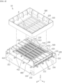
- FIG. 1 is a diagram showing the overall shape of a battery pack 10 according to an embodiment of the present disclosure.
- FIG. 2 is a front view of the battery pack 10 of FIG. 1 .
- FIG. 3 is a top view of the battery pack 10 of FIG. 1 .
- FIG. 4 is a diagram showing a detailed structure of the battery pack 10 of FIG. 1 . At this time, illustration of the second cover 120, which will be described later with reference to FIG. 4 , is omitted.
- the X-axis direction shown in the drawing may mean the front/rear direction
- the Y-axis direction may mean the left/right direction perpendicular to the X-axis direction in the horizontal plane (XY plane)
- the Z-axis direction may mean a vertical direction perpendicular to both the X-axis direction and the Y-axis direction.
- the battery pack 10 may include a pack case 100, a cell module 200, a firefighting tank 300 and an end plate 400.
- the pack case 100 may house the cell module 200 therein.
- the pack case 100 may be provided with a housing space for housing the cell module 200.
- Such a pack case 100 will be discussed more specifically in the related description below.
- the cell module 200 is provided in the inside of the pack case 100 and may include a cell assembly 210.
- the cell assembly 210 may include one or more battery cells.
- each battery cell may mean a secondary battery.
- the battery cell may be provided as a pouch-type battery cell, a cylindrical battery cell, or a prismatic battery cell.
- the battery cell may be a pouch-type battery cell.
- Such battery cells may be arranged to be stacked in one direction and electrically connected to each other.
- Each of the battery cells may include a pair of electrode leads 212.
- the pair of electrode leads 212 of the plurality of battery cells may be formed on both sides in the left/right direction of the cell assembly 210.
- the firefighting tank 300 is disposed on the upper side of the cell assembly 210 and may hold a fire extinguishing agent therein.
- a firefighting tank 300 has an inner space, and can hold a fire extinguishing agent in such an inner space.
- the fire extinguishing agent may be a liquid such as water, salt water and antifreeze.
- the firefighting tank 300 may be housed inside the pack case 100.
- the firefighting tank 300 is configured in a box shape with an opened upper part, and can provide a space in which the fire extinguishing agent can be housed.
- the fire extinguishing agent is discharged from the firefighting tank 300 disposed above the cell assembly 210, so that a thermal event of the cell assembly 210 can be more easily controlled.
- the fire extinguishing agent discharged from the firefighting tank 300 can easily move downward by gravity. Therefore, the heat or fire suppression of the cell assembly 210 can be made more easily by the fire extinguishing agent.
- the end plate 400 may be disposed on at least one of the front side and the rear side of the cell assembly 210.
- the end plate 400 may be configured to support the firefighting tank 300.
- the end plate 400 allows the firefighting tank 300 to be stably fixed inside the pack case 100. Thereby, the fire extinguishing agent is stably discharged from the firefighting tank 300 toward the cell assembly 210, so that the heat or fire of the cell assembly 210 can be suppressed more easily.
- the end plate 400 may be disposed only on the front side or the rear side of the cell assembly 210. Alternatively, the end plate 400 may be disposed on the front side and the rear side of the cell assembly 210, respectively.
- the end plate 400 is illustratively provided as a pair.
- the end plate 400 is disposed between the pack case 100 and the cell assembly 210 in the front/rear direction of the cell assembly 210, and may be configured to press at least one of the front surface and the rear surface when swelling of the battery cell occurs.
- the end plate 400 may be disposed on both sides at the front and rear of the cell assembly 210, and may be configured to press at least one of the front surface and the rear surface of the cell assembly 210 when swelling of the battery cell occurs.
- the end plates 400 it is possible to prevent swelling that may occur in the cell module 200, and at the same time, stably fix the firefighting tank 300 inside the pack case 100. That is, in the present embodiment, since the end plate 400 supports both the firefighting tank 300 and the cell module 200, no additional fastening parts or fastening structures are required to fix or support these members. Thereby, in the present embodiment, there can be provided a battery pack 10, which can increase the efficiency of the assembly process of the battery pack 10 through the end plate 400, can ensure cost competitiveness, and realize a compact structure with higher energy efficiency.
- the firefighting tank 300 may be configured to discharge the fire extinguishing agent to the cell assembly 210 side between both sides of the bottom part when heat is applied from the cell assembly 210.
- the end plate 400 may support both sides of the bottom part of the firefighting tank 300 in the vertical direction.
- the firefighting tank 300 By supporting both sides of the bottom part of the firefighting tank 300 by the end plate 400, the firefighting tank 300 can be more stably supported even when the fire extinguishing agent is discharged from the firefighting tank 300, and the leakage of the fire extinguishing agent to the outside of the bottom part of the firefighting tank 300 can also be effectively prevented, so that the injection efficiency of the fire extinguishing agent into the cell assembly 100 can be increased.
- fixing parts 412 and 422 having a predetermined area and making surface contact with both sides of the bottom part of the firefighting tank 300 may be provided on the upper side of the end plate 400.
- the firefighting tank 300 can be supported more stably by such fixing parts 412 and 422.
- the fixing parts 412 and 422 may be bent from an upper end of the end plate 400 and formed to extend to a predetermined length along an outside direction of the cell assembly. That is, the end plate 400 may have a substantially L-shaped structure.
- the contact area between both sides of the bottom part of the firefighting tank 300 and the end plate 400 is increased, so that the firefighting tank 300 can be supported more stably.
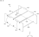
- FIG. 5 is a diagram showing the overall shape of an end plate 400 included in the battery pack 10 of FIG. 1
- FIG. 6 is a front view of the end plate 400 of FIG. 5
- FIG. 7 is a top view of the end plate 400 of FIG. 5
- FIG. 8 is a side view of the end plate 400 of FIG. 5
- FIG. 9 is a side view which projects and shows the inside of the battery pack 10 of FIG. 1 .
- the end plate 400 may include a first plate 410 and a second plate 420.
- the first plate 410 is disposed on the front surface of the cell assembly 210, and can support the front side of the firefighting tank 300 in the vertical direction.
- the aforementioned fixing parts 412 and 422 may include the first fixing part 412. Further, the first plate 410 may include the first fixing part 412.
- the first fixing part 412 may be formed to extend from an upper end of the first plate 410 in the front/rear direction of the cell assembly 210. Further, the first fixing part 412 may be coupled to the front side of the firefighting tank 300 in a vertical direction. And, the first fixing part 412 may make surface contact with the front side of the firefighting tank 300. By the first fixing part 412, the contact area between the front side of the firefighting tank 300 and the first plate 410 is increased, so that the firefighting tank 300 can be stably supported.
- the coupling between the first fixing part 412 and the firefighting tank 300 may be made by a separate fastening member (not shown).
- the coupling between the first fixing part 412 and the firefighting tank 300 may also be made by a separate adhesive member (not shown).
- the second plate 420 is disposed on the rear surface of the cell assembly 210, and may support the rear side of the firefighting tank 300 in the vertical direction.
- the aforementioned fixing parts 412 and 422 may further include a second fixing part 422.
- the second plate 420 may include the second fixing part 422.
- the second fixing part 422 may be formed to extend from an upper end of the second plate 420 in the front/rear direction of the cell assembly 210. Further, the second fixing part 422 may be coupled to the rear side of the firefighting tank 300 in a vertical direction. And, the second fixing part 422 may make surface contact with the rear side of the firefighting tank 300. Through the second fixing part 422, the contact area between the rear side of the firefighting tank 300 and the second plate 420 is increased, so that the firefighting tank 300 can be stably supported.
- the coupling between the second fixing part 422 and the firefighting tank 300 may be made by a separate fastening member (not shown).
- the coupling between the second fixing part 422 and the firefighting tank 300 can be made by a separate adhesive member (not shown).
- the firefighting tank 300 can be stably fixed within the pack case 100. Thereby, the fire extinguishing agent is stably discharged from the firefighting tank 300 toward the cell assembly 210, so that the heat or fire suppression of the cell assembly 210 can be made more easily.
- FIG. 10 is a top view which projects and shows the inside of the battery pack 10 of FIG. 1 . At this time, illustration of the firefighting tank 300 described above with reference to FIG. 10 is omitted.
- the aforementioned pack case 100 may further include a guide protrusion 150.
- the guide protrusion 150 is formed to protrude from the bottom part of the pack case 100 in a vertical direction, and is provided apart from the front surface and the rear surface of the cell assembly at a specified interval in the front/rear direction of the cell assembly 210.
- the guide protrusion 150 may be provided integrally with the bottom part of the pack case 100, or may be mounted as a separate member.
- Such a guide protrusion 150 may be disposed on the opposite side of the cell assembly 210 with the end plate 400 interposed therebetween.
- the guide protrusion 150 may include a first protrusion 152 and a second protrusion 154.
- the first protrusion 152 may be formed apart from the front surface of the cell assembly 210 at a specified interval in the front/rear direction of the cell assembly 210.
- the first plate 410 is disposed between the first protrusion 152 and the front surface of the cell assembly 210 in the front/rear direction of the cell assembly 210, and may be configured to press the front surface of the cell assembly 210 when swelling of the battery cell occurs.
- the first plate 410 may be configured to press the front surface of the cell assembly 210 when swelling of the battery cell occurs, in a state in which the cell assembly 210 is supported in the front/rear direction by the first protrusion 152. Accordingly, the first plate 410 can effectively suppress a swelling phenomenon of the cell module 200.
- the second protrusion 154 may be formed apart from the rear surface of the cell assembly 210 at a specified interval in the front/rear direction of the cell assembly 210.
- the second plate 420 is disposed between the second protrusion 154 and the rear surface of the cell assembly 210 in the front/rear direction of the cell assembly 210, and may be configured to press the rear surface of the cell assembly 210 when swelling of the battery cell occurs.
- the second plate 420 may be configured to press the rear surface of the cell assembly 210 when swelling of the battery cell occurs, in a state in which the cell assembly 210 is supported in the front/rear direction by the second protrusion 154. Accordingly, the second plate 420 can effectively suppress a swelling phenomenon of the cell module 200.
- the end plate 400 can more stably press the front surface and the rear surface of the cell assembly 210, in a state in which the cell assembly 210 is supported in the front/rear direction by the guide protrusion 150.
- the swelling phenomenon that may occur in the cell module 200 can be more effectively suppressed.
- the end plate 400 is stably supported in the front/rear direction of the cell assembly 210 by the configuration of the guide protrusion 150 described above, the firefighting tank 300 can be more stably fixed within the pack case 100 by the end plate 400.
- the fire extinguishing agent is stably discharged from the firefighting tank 300 toward the cell assembly 210, so that the heat or fire suppression of the cell assembly 210 can be made more easily.
- the battery pack 10 may further include a connection part 500.
- connection part 500 may connect the first plate 410 and the second plate 420 in the front/rear direction of the cell assembly 210.
- the connection part 500 may be a long bolt extending in the front/rear direction of the cell assembly 210. Accordingly, the first plate 410 and the second plate 420 may be interconnected.
- connection part 500 will be described in more detail.
- the connection part 500 may include a first connection member 510 and a second connection member 520.
- the first connection member 510 may connect an upper end of the first plate 410 and an upper end of the second plate 420 in the front/rear direction of the cell assembly 210. At this time, the first connection members 510 may be disposed in plural numbers along the left/right direction of the cell assembly 210 .
- the second connection member 520 may connect the lower end of the first plate 410 and the lower end of the second plate 420 in the front/rear direction of the cell assembly 210. At this time, the second connection members 520 may be disposed in plural numbers along the left/right direction of the cell assembly 210.
- connection part 500 can connect the upper and lower ends of the first plate 410 and the second plate 420 at the same time.
- the first plate 410 and the second plate 420 can be stably connected to each other in the front/rear direction of the cell assembly 210.
- the front and back surfaces of the cell assembly 210 can be pressed more stably and effectively by the end plates 400. Further, since the first plate 410 and the second plate 420 of the end plate 400 are stably connected to each other by the configuration of the connection part 500 described above, the firefighting tank 300 can be more stably fixed within the pack case 100 by the end plate 400.
- the fire extinguishing agent is stably discharged from the firefighting tank 300 toward the cell assembly 210, so that the heat or fire suppression of the cell assembly 210 can be made more easily.
- the cell assembly 210 may be disposed between the first connection member 510 and the second connection member 520 in the vertical direction. Therefore, interference between the cell assembly 210 and the connector part 500 can be prevented.
- FIG. 11 is a diagram showing an end plate 402 according to another embodiment of the present disclosure.
- the end plate 402 may include a first plate 410 and a second plate 420.
- the first plate 410 may include a first fixing part 414, and the second plate 420 may include a second fixing part 424.
- the first fixing part 414 may be formed to extend from the upper end of the first plate 410 in the front/rear direction of the cell assembly 210.
- the first fixing part 414 may be configured to extend long in the left/right direction of the cell assembly 210 from the upper end of the first plate 410.
- the second fixing part 424 may be formed to extend from an upper end of the second plate 420 in the front/rear direction of the cell assembly 210.
- the second fixing part 424 may be configured to extend long in the left/right direction of the cell assembly 210 from the upper end of the second plate 420.
- the contact area between the first plate 410, the second plate 420 and the firefighting tank 300 can be further increased.
- the firefighting tank 300 can be more stably fixed to the upper side of the end plate 402.
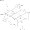
- FIG. 12 is a diagram showing an end plate 404 according to another embodiment of the present disclosure.
- FIG. 13 is a side view which projects and shows the inside of the battery pack 10 to which the end plate 404 of FIG. 12 is applied.
- the end plate 404 may include a first plate 410 and a second plate 420.
- the first plate 410 may include a first fixing part 416, and the second plate 420 may include a second fixing part 426.
- the first fixing part 416 may include a first horizontal plate 4162 and a first vertical plate 4164.
- the first horizontal plate 4162 may be formed to extend from an upper end of the first plate 410 in the front/rear direction of the cell assembly 210.
- the first horizontal plate 4162 may be coupled to the front side of the firefighting tank 300 in the vertical direction.
- the first vertical plate 4164 may be formed to extend in the vertical direction from an end of the first horizontal plate 4162.
- the first vertical plate 4164 may support the front side surface of the firefighting tank 300 in the front/rear direction of the cell assembly 210.
- the second fixing part 426 may include a second horizontal plate 4262 and a second vertical plate 4264.
- the second horizontal plate 4262 may be formed to extend from an upper end of the second plate 420 in the front/rear direction of the cell assembly 210.
- the second horizontal plate 4262 may be coupled to the rear side of the firefighting tank 300 in the vertical direction.
- the second vertical plate 4264 may be formed to extend in the vertical direction from an end of the second horizontal plate 4262.
- the second vertical plate 4264 may support the rear side surface of the firefighting tank 300 in the front/rear direction of the cell assembly 210.
- the end plate 404 can support the firefighting tank 300 not only in the vertical direction but also in the front/rear direction, so that the firefighting tank 300 can be more stably fixed within the pack case 100.
- the aforementioned pack case 100 may include a first cover 110, a second cover 120 and a gas flow passage 130.
- the first cover 110 may be provided with a housing space for housing the cell module 200. Such a first cover 110 may be coupled with a second cover 120, which will be described later, to thereby house the cell module 200 therein. Further, the bottom surface of the first cover 110 may constitute the bottom part of the pack case 100.
- the aforementioned guide protrusion 150 is provided on the first cover 110, and may be provided on the bottom surface of the first cover 110 constituting the bottom part of the pack case 100.
- the second cover 120 may be coupled to the first cover 110 in a vertical direction. At this time, the second cover 120 may be disposed on the upper part of the first cover 110.
- the upper part of the firefighting tank 300 may be covered by the second cover 120 of the pack case 100, as shown in FIG. 9 .
- the front surface, the rear surface, the left side surface and the right side surface of the pack case 100 may be formed as shown in FIG. 1 .
- the coupling between the first cover 110 and the second cover 120 can be made by a plurality of fastening members (not shown).
- the pack case 100 may not be configured separately into the first cover 110 and the second cover 120, but may be configured integrally.
- the gas flow passage 130 is for guiding air inflow into the pack case 100 and gas discharge inside the pack case 100, and may be provided in the second cover 120.
- the gas flow passage 130 may include an air inflow part 132 and a gas discharge part 134.
- the air inflow part 132 may be formed on a rear side of the second cover 120. At this time, the air inflow part 132 may allow external air to flow into the pack case 100.
- the gas discharge part 134 may be formed on the front side of the second cover 120. At this time, the gas discharge part 134 may allow the gas inside the pack case 100 to be discharged to the outside.
- the air inflow part 132 and the gas discharge part 134 may be formed with a mesh structure.
- the air inflow part 132 having the mesh structure foreign matter of a predetermined size is prevented from entering inside the pack case 100, and the air can smoothly flow into the inside of the pack case 100.
- the gas discharge part 134 having the mesh structure the foreign matter is prevented from entering inside the pack case 100, and venting gas generated in the inside of the pack case 100 can be discharged to the outside of the pack case 100.
- the air inflow part 132 allows air to flow smoothly into the pack case 100, thereby preventing negative pressure from occurring inside the firefighting tank 300. Further, the air inflow part 132 can prevent a decrease in the injection speed or a decrease in the injection amount of the fire extinguishing agent into the cell module 200, which is caused by the generation of negative pressure inside the firefighting tank 300.
- the cell module 200 may further include a busbar frame 220.
- the busbar frame 220 is for sensing the voltage of the cell assembly 210, and may be provided as a pair to support one side surface and the other side surface of the cell assembly 210 in the left/right direction.
- the busbar frame 220 may include a first busbar frame 222 and a second busbar frame 224.
- the first busbar frame 222 may support one side surface (e.g., left side surface) in the left/right direction of the cell assembly 210.
- a busbar (not shown) provided in the first busbar frame 222 may be connected to an electrode lead 212 formed on one side surface in a left/right direction of the cell assembly 210.
- the second busbar frame 224 may support the other side surface (e.g., right side surface) in the left/right direction of the cell assembly 210.
- the busbar (not shown) provided in the second busbar frame 224 may be connected to the electrode lead 212 formed on the other side surface in the left/right direction of the cell assembly 210.
- the firefighting tank 300 may be configured such that at least a portion thereof is melted by heat applied from the cell assembly 210 to discharge the fire extinguishing agent.
- the portion indicated by A of the firefighting tank 300 may be melted by heat.
- the fire extinguishing agent may be discharged between both sides of the bottom part of the firefighting tank 300 towards the cell assembly 210.
- at least a portion of the firefighting tank 300 may be made of a material that can be melted by heat applied from the cell assembly 210.
- the firefighting tank 300 may be entirely made of a plastic material.
- the aforementioned pack case 100 may be configured to be stacked in the vertical direction. That is, the battery pack 10 of the present disclosure may be configured by stacking different pack cases 100 in the vertical direction.
- each pack case 100 since each pack case 100 has a cell module 200 therein, it is possible to realize battery packs 10 with various capacities depending on the number of stacked pack cases 100.
- each pack case 100 since each pack case 100 has a firefighting tank 300 therein, and thus, when a thermal event occurs in the cell assembly 210 inside some pack case 100, this thermal event can be prevented from being transferred to the cell assembly 210 inside the other pack case 100.
- the firefighting tank 300 may illustratively include the base plate 310 and the side wall 320. At this time, the base plate 310 may constitute the bottom part of the firefighting tank 300.
- the side wall 320 may be configured to protrude upward from the corner of the base plate 310.
- the firefighting tank 300 has a bottom and a side part formed by the base plate 310 and the side wall 320, thereby capable of forming a space in which the fire extinguishing agent is housed.
- the upper part of the firefighting tank 300 may be sealed by the pack case 100.
- the firefighting tank 300 may separately include an upper cover configured to seal the fire extinguishing agent-housing space thereon.
- the base plate 310 of such a firefighting tank 300 may be formed to have different thicknesses in the vertical direction for each portion.
- the base plate 310 may be configured to have a thin thickness at a specific portion, as shown by a section A in FIG. 4 .
- the base plate 310 may be configured in the form of a plastic injection molding having a thickness of 1 mm as a whole, and a portion indicated by A may have a thickness of 0.5 mm.
- a thinly formed portion of the base plate 310 may function as a fragile part. That is, when a thermal event such as thermal runaway occurs in the cell assembly 210 and heat is applied to the fragile part, the fragile part may first be broken. And, when the fragile part is broken, the fire extinguishing agent housed in the firefighting tank 300 may be discharged toward the cell assembly 210 through the broken fragile part. Thereby, a configuration for injecting the fire extinguishing agent into the cell assembly 210 can be realized with a simpler structure, and the fire extinguishing agent can be injected into the cell assembly 210 more quickly.
- At least a portion of the base plate 310 constituting the bottom part of the firefighting tank 300 may protrude downward from the base plate 310.
- a portion of the base plate 310 including the fragile part indicated by A in FIG. 4 may protrude downward from the base plate 310.
- at least a portion of the base plate 310 may be disposed between the first plate 410 and the second plate 420 in the front/rear direction of the cell assembly 210.
- the firefighting tank 300 can be prevented from moving forward and backward by the end plate 400.
- a portion where the fire extinguishing agent is discharged to the cell assembly 210 from the firefighting tank 300 may be disposed between the first plate 410 and the second plate 420.
- the fire extinguishing agent can be completely discharged toward the cell assembly 210 from the firefighting tank 300, so that heat or fire suppression of the cell assembly 210 can be more easily made.
- the firefighting tank 300 is more stably fixed in the pack case 100 through the end plates 400, 402, and 404, so that a thermal event inside the pack case 100 can be quickly controlled, and at the same time, swelling of the cell module 200 can be effectively prevented.
- the battery pack 10 since the battery pack 10 according to the embodiment of the present disclosure does not require an additional structure for supporting the firefighting tank 300, apart from a structure for preventing swelling, it is possible to secure cost competitiveness while increasing the efficiency of the manufacturing process, and realize a compact structure with higher energy efficiency.
- the battery pack 10 may further include, in addition to the pack case 100 and the cell module 200, various devices for controlling charging and discharging the cell module 200, such as a BMS (Battery Management System), a current sensor, a fuse, and the like.
- BMS Battery Management System
- the battery pack 10 according to the present disclosure can be used as a home battery pack. Further, at least one battery pack 10 according to the present disclosure can be provided as an energy source to configure an energy storage system (ESS).
- ESS energy storage system
Landscapes
- Chemical & Material Sciences (AREA)
- Chemical Kinetics & Catalysis (AREA)
- Electrochemistry (AREA)
- General Chemical & Material Sciences (AREA)
- Engineering & Computer Science (AREA)
- Manufacturing & Machinery (AREA)
- Battery Mounting, Suspending (AREA)
Abstract
Description
- This application claims the benefit of
Korean Patent Application No. 10-2022-0030830 filed on March 11, 2022 - The present disclosure relates to a battery pack and an energy storage system including the same, and more particularly, to a battery pack configured to ensure safety even when a thermal event occurs, and an energy storage system including the same.
- As the demands for portable electronic products such as notebooks, video cameras and cellular phones are rapidly increased in these days, and development of electric vehicles, energy storage batteries, robots, satellites, etc. is under active progress, numerous studies are being made on high-performance secondary batteries capable of being repeatedly charged and discharged.
- Currently, nickel-cadmium batteries, nickel-hydrogen batteries, nickel-zinc batteries, lithium secondary batteries or the like are commercially available as secondary batteries. Among them, lithium secondary batteries have come into the spotlight because they have advantages, for example, hardly exhibiting memory effects in comparison with nickel-based secondary batteries and thus being freely charged and discharged, and having very low self-discharge rate and high energy density.
- The lithium secondary battery mainly uses lithium oxide and carbonaceous material as a cathode active material and an anode active material, respectively. The lithium secondary battery includes an electrode assembly in which a cathode plate and an anode plate respectively coated with the cathode active material and the anode active material are disposed with a separator interposed between them, and an exterior material which seals and receives the electrode assembly together with an electrolyte solution.
- Meanwhile, depending on the shape of the battery case, a lithium secondary battery may be classified into a can-type secondary battery where the electrode assembly is mounted in a metal can, and a pouch-type battery where the electrode assembly is mounted in a pouch of an aluminum laminate. In addition, depending on the shape of the metal can, the can-type secondary battery may be further classified into a cylindrical battery and a prismatic battery.
- Here, the pouch of the pouch-type secondary battery can be largely divided into a lower sheet and an upper sheet covering it. At this time, an electrode assembly formed by stacking and winding a cathode, an anode and a separator is housed in the pouch. Then, after housing the electrode assembly, the edges of the upper sheet and the lower sheet are sealed by heat sealing or the like. In addition, the electrode tab drawn out from each electrode may be coupled to the electrode lead, and an insulating film may be added to a portion wherein the electrode lead comes into contact with the sealing part.
- Thus, the pouch-type secondary battery can have the flexibility to be configured in various forms. In addition, the pouch-type secondary battery has the advantage that a secondary battery having the same capacity can be realized with a smaller volume and mass.
- Application fields of such lithium secondary batteries tend to gradually extend to Energy Storage System (ESS) and the like. The lithium secondary battery is made into a dense structure in which a plurality of battery cells are overlapped or stacked by themselves or in a state of being mounted in a cartridge or the like so as to provide high voltage and high current, and then is used as a cell module or a battery pack in which they are electrically connected. As an example, the energy storage system may also be composed of an assembly of home battery packs used in various types of houses (e.g., a detached house, an apartment, etc.).
- In such a battery pack configuration, one of the typically important issues is safety. In particular, when a thermal event occurs in one battery cell among a plurality of battery cells included in the battery pack, such an event need to be suppressed from propagating to other battery cells. If thermal propagation between battery cells is not properly suppressed, this causes a thermal event in several battery cells included in the battery pack, which may cause bigger problems such as ignition or explosion of the battery pack. Moreover, the ignition or explosion that occurs in the battery pack may cause great damage to human life or loss of property in the periphery. In particular, in the case of a home battery pack, if ignition or explosion occurs, it may harm the safety of people living in the house, and may spread into a house fire to cause more damage. Therefore, in the case of such a battery pack, a configuration capable of appropriately controlling the above-mentioned thermal event is required.
- In particular, in the case of such a battery pack, it is desired to ensure that the configuration for controlling the above thermal event can be safely fixed within the battery pack, thereby more stably controlling the thermal event.
- The present disclosure has been designed to solve the above problems, and an object thereof is to provide a battery pack having an improved structure so as to properly control a thermal event which occurs inside the battery pack, and an energy storage system including the same.
- However, the objects and advantages of the present disclosure are not limited to those described above, and other objects and advantages not mentioned above will be clearly understood by those skilled in the art from the following description.
- In order to achieve the above object, according to an embodiment of the present disclosure, there is provided a battery pack comprising: a pack case, a cell module provided inside the pack case and including a cell assembly having a plurality of battery cells, a firefighting tank disposed on an upper side of the cell assembly and holding a fire extinguishing agent in an internal space, and an end plate disposed on at least one of the front and rear sides of the cell assembly and configured to support the firefighting tank.
- Preferably, the end plates may be disposed on both sides at the front and rear of the cell assembly, and may be configured to press at least one of front and rear surfaces of the cell assembly when swelling of the battery cell occurs.
- Preferably, the firefighting tank may be configured to discharge the fire extinguishing agent between both sides of the bottom part toward the cell assembly when heat is applied from the cell assembly, and the end plates may support both sides of the bottom part of the firefighting tank in a vertical direction.
- Preferably, a fixing part having a predetermined area and making surface contact with both sides of the bottom part of the firefighting tank may be provided on the upper side of the end plate.
- Preferably, the fixing part may be bent from an upper end of the end plate and formed to extend to a predetermined length along an outside direction of the cell assembly.
- Preferably, the end plate may include a first plate disposed on the front surface of the cell assembly and supporting the front side of the firefighting tank in a vertical direction, and a second plate disposed on the rear surface of the cell assembly and supporting the rear side of the firefighting tank in the vertical direction.
- Preferably, the fixing part may include a first fixing part that is formed to extend from the upper end of the first plate in the front/rear direction of the cell assembly, and is coupled to the front side of the firefighting tank in the vertical direction.
- Preferably, the first fixing part may make surface contact with the front side of the firefighting tank.
- Preferably, the fixing part may further include a second fixing part that is formed to extend from the upper end of the second plate in the front/rear direction of the cell assembly, and is coupled to the rear side of the firefighting tank in the vertical direction.
- Preferably, the second fixing part may make surface contact with the rear side of the firefighting tank.
- Preferably, the pack case may include a guide protrusion that is formed to protrude from the bottom part of the pack case in a vertical direction, and is provided apart from the front surface and the rear surface of the cell assembly at a specified interval in the front/rear direction of the cell assembly.
- Preferably, the guide protrusion may be disposed on the opposite side of the cell assembly with the end plate interposed therebetween.
- Preferably, the guide protrusion may include a first protrusion formed apart from the front surface of the cell assembly at a specified interval in the front/rear direction of the cell assembly, and a second protrusion formed apart from the rear surface of the cell assembly at a specified interval in the front/rear direction of the cell assembly.
- Preferably, the first plate may be disposed between the first protrusion and the front surface of the cell assembly in the front/rear direction of the cell assembly, and configured to press the front surface of the cell assembly when swelling of the battery cell occurs.
- Preferably, the second plate may be disposed between the second protrusion and the rear surface of the cell assembly in the front/rear direction of the cell assembly, and configured to press the rear surface of the cell assembly when swelling of the battery cell occurs.
- Preferably, the battery pack may further comprise a connection part that connects the first plate and the second plate in the front/rear direction of the cell assembly.
- Preferably, the connection part may include a first connection member that connects an upper end of the first plate and an upper end of the second plate in the front/rear direction of the cell assembly, and is disposed in plural numbers along a left/right direction of the cell assembly, and a second connection member that connects the lower end of the first plate and the lower end of the second plate in the front/rear direction of the cell assembly, and is disposed in plurality along the left/right direction of the cell assembly.
- According to another embodiment of the present disclosure, there is provided an energy storage system comprising at least one battery pack as described above.
- According to some embodiments of the present disclosure, the firefighting tank can be more stably fixed within the pack case through the end plate to quickly control a thermal event inside the pack case, and at the same time, effectively prevent a swelling phenomenon of the cell module.
- Also, the battery pack according to some embodiments of the present disclosure does not require an additional structure for supporting the firefighting tank, apart from the structure for preventing swelling, thereby securing cost competitiveness while increasing the efficiency of the manufacturing process, and realizing a compact structure with higher energy efficiency.
- In addition, several other advantageous effects can be further achieved according to various embodiments of the present disclosure. Such various effects of the present disclosure will be described in detail in respective embodiments, but as for effects that can be easily understood by those skilled in the art, the description thereof will be omitted.
- The following drawings attached thereto illustrate preferred embodiments of the invention, and serve to further understand the technical idea of the invention together with the contents of the invention described above. The disclosure should not be construed as being limited only to the embodiments as illustrated in the drawings.
-
FIG. 1 is a diagram showing the overall shape of a battery pack according to an embodiment of the present disclosure; -
FIG. 2 is a front view of the battery pack ofFIG. 1 ; -
FIG. 3 is a top view of the battery pack ofFIG. 1 ; -
FIG. 4 is a diagram showing a detailed structure of the battery pack ofFIG. 1 ; -
FIG. 5 is a diagram showing the overall shape of an end plate included in the battery pack ofFIG. 1 ; -
FIG. 6 is a front view of the end plate ofFIG. 5 ; -
FIG. 7 is a top view of the end plate ofFIG. 5 ; -
FIG. 8 is a side view of the end plate ofFIG. 5 ; -
FIG. 9 is a side view which projects and shows the inside of the battery pack ofFIG. 1 ; -
FIG. 10 is a top view which projects and shows the inside of the battery pack ofFIG. 1 ; -
FIG. 11 is a diagram showing an end plate according to another embodiment of the present disclosure; -
FIG. 12 is a diagram showing an end plate according to another embodiment of the present disclosure; and -
FIG. 13 is a side view which projects and shows the inside of the battery pack to which the end plate ofFIG. 12 is applied. - Hereinafter, preferred embodiments of the present invention will be described in detail with reference to the accompanying drawings. Prior to the description, it should be understood that the terms or words used in the specification and the appended claims should not be construed as being limited to general and dictionary meanings, but interpreted based on the meanings and concepts corresponding to technical aspects of the invention on the basis of the principle that the inventor is allowed to define terms appropriately for the best explanation.
- Therefore, the embodiments described herein and the configurations shown in the drawings are only most preferable embodiments of the present disclosure and do not represent the entire spirit of the present disclosure, so it should be appreciated that there may be various equivalents and modifications that can replace the embodiments and configurations at the time at which the present application is filed.
-
FIG. 1 is a diagram showing the overall shape of abattery pack 10 according to an embodiment of the present disclosure.FIG. 2 is a front view of thebattery pack 10 ofFIG. 1 .FIG. 3 is a top view of thebattery pack 10 ofFIG. 1 .FIG. 4 is a diagram showing a detailed structure of thebattery pack 10 ofFIG. 1 . At this time, illustration of thesecond cover 120, which will be described later with reference toFIG. 4 , is omitted. - In some embodiments of the present disclosure, the X-axis direction shown in the drawing may mean the front/rear direction, the Y-axis direction may mean the left/right direction perpendicular to the X-axis direction in the horizontal plane (XY plane), and the Z-axis direction may mean a vertical direction perpendicular to both the X-axis direction and the Y-axis direction.
- Referring to
FIGS. 1 to 4 , thebattery pack 10 according to an embodiment of the present disclosure may include apack case 100, acell module 200, afirefighting tank 300 and anend plate 400. - The
pack case 100 may house thecell module 200 therein. For this purpose, thepack case 100 may be provided with a housing space for housing thecell module 200. Such apack case 100 will be discussed more specifically in the related description below. - The
cell module 200 is provided in the inside of thepack case 100 and may include acell assembly 210. - The
cell assembly 210 may include one or more battery cells. Here, each battery cell may mean a secondary battery. The battery cell may be provided as a pouch-type battery cell, a cylindrical battery cell, or a prismatic battery cell. As an example, the battery cell may be a pouch-type battery cell. - Such battery cells may be arranged to be stacked in one direction and electrically connected to each other. Each of the battery cells may include a pair of electrode leads 212. At this time, the pair of electrode leads 212 of the plurality of battery cells may be formed on both sides in the left/right direction of the
cell assembly 210. - The
firefighting tank 300 is disposed on the upper side of thecell assembly 210 and may hold a fire extinguishing agent therein. Such afirefighting tank 300 has an inner space, and can hold a fire extinguishing agent in such an inner space. As an example, the fire extinguishing agent may be a liquid such as water, salt water and antifreeze. In addition, thefirefighting tank 300 may be housed inside thepack case 100. - The
firefighting tank 300 is configured in a box shape with an opened upper part, and can provide a space in which the fire extinguishing agent can be housed. - According to some embodiments of the present disclosure, the fire extinguishing agent is discharged from the
firefighting tank 300 disposed above thecell assembly 210, so that a thermal event of thecell assembly 210 can be more easily controlled. In particular, the fire extinguishing agent discharged from thefirefighting tank 300 can easily move downward by gravity. Therefore, the heat or fire suppression of thecell assembly 210 can be made more easily by the fire extinguishing agent. - The
end plate 400 may be disposed on at least one of the front side and the rear side of thecell assembly 210. Theend plate 400 may be configured to support thefirefighting tank 300. - The
end plate 400 allows thefirefighting tank 300 to be stably fixed inside thepack case 100. Thereby, the fire extinguishing agent is stably discharged from thefirefighting tank 300 toward thecell assembly 210, so that the heat or fire of thecell assembly 210 can be suppressed more easily. - At this time, the
end plate 400 may be disposed only on the front side or the rear side of thecell assembly 210. Alternatively, theend plate 400 may be disposed on the front side and the rear side of thecell assembly 210, respectively. - In the present embodiment, it will be described that the
end plate 400 is illustratively provided as a pair. - The
end plate 400 is disposed between thepack case 100 and thecell assembly 210 in the front/rear direction of thecell assembly 210, and may be configured to press at least one of the front surface and the rear surface when swelling of the battery cell occurs. - That is, the
end plate 400 may be disposed on both sides at the front and rear of thecell assembly 210, and may be configured to press at least one of the front surface and the rear surface of thecell assembly 210 when swelling of the battery cell occurs. - By pressing the
end plate 400 in this way, a swelling phenomenon that may occur in thecell module 200 inside thepack case 100 can be effectively suppressed. - Ultimately, through the
end plates 400, it is possible to prevent swelling that may occur in thecell module 200, and at the same time, stably fix thefirefighting tank 300 inside thepack case 100. That is, in the present embodiment, since theend plate 400 supports both thefirefighting tank 300 and thecell module 200, no additional fastening parts or fastening structures are required to fix or support these members. Thereby, in the present embodiment, there can be provided abattery pack 10, which can increase the efficiency of the assembly process of thebattery pack 10 through theend plate 400, can ensure cost competitiveness, and realize a compact structure with higher energy efficiency. - The
firefighting tank 300 may be configured to discharge the fire extinguishing agent to thecell assembly 210 side between both sides of the bottom part when heat is applied from thecell assembly 210. Here, theend plate 400 may support both sides of the bottom part of thefirefighting tank 300 in the vertical direction. - By supporting both sides of the bottom part of the
firefighting tank 300 by theend plate 400, thefirefighting tank 300 can be more stably supported even when the fire extinguishing agent is discharged from thefirefighting tank 300, and the leakage of the fire extinguishing agent to the outside of the bottom part of thefirefighting tank 300 can also be effectively prevented, so that the injection efficiency of the fire extinguishing agent into thecell assembly 100 can be increased. - Meanwhile, fixing
parts firefighting tank 300 may be provided on the upper side of theend plate 400. - The
firefighting tank 300 can be supported more stably by such fixingparts - Further, the fixing
parts end plate 400 and formed to extend to a predetermined length along an outside direction of the cell assembly. That is, theend plate 400 may have a substantially L-shaped structure. - According to such configuration of the present disclosure, the contact area between both sides of the bottom part of the
firefighting tank 300 and theend plate 400 is increased, so that thefirefighting tank 300 can be supported more stably. - Below, the
end plate 400 will be described in more detail. -
FIG. 5 is a diagram showing the overall shape of anend plate 400 included in thebattery pack 10 ofFIG. 1 ,FIG. 6 is a front view of theend plate 400 ofFIG. 5 .FIG. 7 is a top view of theend plate 400 ofFIG. 5 .FIG. 8 is a side view of theend plate 400 ofFIG. 5 .FIG. 9 is a side view which projects and shows the inside of thebattery pack 10 ofFIG. 1 . - Referring to
FIGS. 4 to 9 , theend plate 400 may include afirst plate 410 and asecond plate 420. - The
first plate 410 is disposed on the front surface of thecell assembly 210, and can support the front side of thefirefighting tank 300 in the vertical direction. - Meanwhile, the aforementioned fixing
parts part 412. Further, thefirst plate 410 may include the first fixingpart 412. - The
first fixing part 412 may be formed to extend from an upper end of thefirst plate 410 in the front/rear direction of thecell assembly 210. Further, the first fixingpart 412 may be coupled to the front side of thefirefighting tank 300 in a vertical direction. And, the first fixingpart 412 may make surface contact with the front side of thefirefighting tank 300. By the first fixingpart 412, the contact area between the front side of thefirefighting tank 300 and thefirst plate 410 is increased, so that thefirefighting tank 300 can be stably supported. - At this time, the coupling between the first fixing
part 412 and thefirefighting tank 300 may be made by a separate fastening member (not shown). Alternatively, the coupling between the first fixingpart 412 and thefirefighting tank 300 may also be made by a separate adhesive member (not shown). - The
second plate 420 is disposed on the rear surface of thecell assembly 210, and may support the rear side of thefirefighting tank 300 in the vertical direction. - Meanwhile, the aforementioned fixing
parts second fixing part 422. And, thesecond plate 420 may include thesecond fixing part 422. - The
second fixing part 422 may be formed to extend from an upper end of thesecond plate 420 in the front/rear direction of thecell assembly 210. Further, thesecond fixing part 422 may be coupled to the rear side of thefirefighting tank 300 in a vertical direction. And, thesecond fixing part 422 may make surface contact with the rear side of thefirefighting tank 300. Through thesecond fixing part 422, the contact area between the rear side of thefirefighting tank 300 and thesecond plate 420 is increased, so that thefirefighting tank 300 can be stably supported. - At this time, the coupling between the
second fixing part 422 and thefirefighting tank 300 may be made by a separate fastening member (not shown). Alternatively, the coupling between thesecond fixing part 422 and thefirefighting tank 300 can be made by a separate adhesive member (not shown). - Due to the configuration of the
aforementioned end plate 400, thefirefighting tank 300 can be stably fixed within thepack case 100. Thereby, the fire extinguishing agent is stably discharged from thefirefighting tank 300 toward thecell assembly 210, so that the heat or fire suppression of thecell assembly 210 can be made more easily. -
FIG. 10 is a top view which projects and shows the inside of thebattery pack 10 ofFIG. 1 . At this time, illustration of thefirefighting tank 300 described above with reference toFIG. 10 is omitted. - Referring to
FIGS. 4 to 10 , theaforementioned pack case 100 may further include aguide protrusion 150. - The
guide protrusion 150 is formed to protrude from the bottom part of thepack case 100 in a vertical direction, and is provided apart from the front surface and the rear surface of the cell assembly at a specified interval in the front/rear direction of thecell assembly 210. Here, theguide protrusion 150 may be provided integrally with the bottom part of thepack case 100, or may be mounted as a separate member. - Such a
guide protrusion 150 may be disposed on the opposite side of thecell assembly 210 with theend plate 400 interposed therebetween. - Specifically, the
guide protrusion 150 may include afirst protrusion 152 and asecond protrusion 154. - The
first protrusion 152 may be formed apart from the front surface of thecell assembly 210 at a specified interval in the front/rear direction of thecell assembly 210. - At this time, the
first plate 410 is disposed between thefirst protrusion 152 and the front surface of thecell assembly 210 in the front/rear direction of thecell assembly 210, and may be configured to press the front surface of thecell assembly 210 when swelling of the battery cell occurs. - Specifically, the
first plate 410 may be configured to press the front surface of thecell assembly 210 when swelling of the battery cell occurs, in a state in which thecell assembly 210 is supported in the front/rear direction by thefirst protrusion 152. Accordingly, thefirst plate 410 can effectively suppress a swelling phenomenon of thecell module 200. - The
second protrusion 154 may be formed apart from the rear surface of thecell assembly 210 at a specified interval in the front/rear direction of thecell assembly 210. - At this time, the
second plate 420 is disposed between thesecond protrusion 154 and the rear surface of thecell assembly 210 in the front/rear direction of thecell assembly 210, and may be configured to press the rear surface of thecell assembly 210 when swelling of the battery cell occurs. - Specifically, the
second plate 420 may be configured to press the rear surface of thecell assembly 210 when swelling of the battery cell occurs, in a state in which thecell assembly 210 is supported in the front/rear direction by thesecond protrusion 154. Accordingly, thesecond plate 420 can effectively suppress a swelling phenomenon of thecell module 200. - Similar to the configuration described above, the
end plate 400 can more stably press the front surface and the rear surface of thecell assembly 210, in a state in which thecell assembly 210 is supported in the front/rear direction by theguide protrusion 150. - Accordingly, the swelling phenomenon that may occur in the
cell module 200 can be more effectively suppressed. Further, since theend plate 400 is stably supported in the front/rear direction of thecell assembly 210 by the configuration of theguide protrusion 150 described above, thefirefighting tank 300 can be more stably fixed within thepack case 100 by theend plate 400. - Accordingly, the fire extinguishing agent is stably discharged from the
firefighting tank 300 toward thecell assembly 210, so that the heat or fire suppression of thecell assembly 210 can be made more easily. - Referring back to
FIGS. 4 to 10 , thebattery pack 10 may further include aconnection part 500. - The
connection part 500 may connect thefirst plate 410 and thesecond plate 420 in the front/rear direction of thecell assembly 210. As an example, theconnection part 500 may be a long bolt extending in the front/rear direction of thecell assembly 210. Accordingly, thefirst plate 410 and thesecond plate 420 may be interconnected. - Below, the
connection part 500 will be described in more detail. - The
connection part 500 may include afirst connection member 510 and asecond connection member 520. - The
first connection member 510 may connect an upper end of thefirst plate 410 and an upper end of thesecond plate 420 in the front/rear direction of thecell assembly 210. At this time, thefirst connection members 510 may be disposed in plural numbers along the left/right direction of thecell assembly 210 . - The
second connection member 520 may connect the lower end of thefirst plate 410 and the lower end of thesecond plate 420 in the front/rear direction of thecell assembly 210. At this time, thesecond connection members 520 may be disposed in plural numbers along the left/right direction of thecell assembly 210. - In this manner, the
connection part 500 can connect the upper and lower ends of thefirst plate 410 and thesecond plate 420 at the same time. Thus, thefirst plate 410 and thesecond plate 420 can be stably connected to each other in the front/rear direction of thecell assembly 210. - Thereby, the front and back surfaces of the
cell assembly 210 can be pressed more stably and effectively by theend plates 400. Further, since thefirst plate 410 and thesecond plate 420 of theend plate 400 are stably connected to each other by the configuration of theconnection part 500 described above, thefirefighting tank 300 can be more stably fixed within thepack case 100 by theend plate 400. - Thereby, the fire extinguishing agent is stably discharged from the
firefighting tank 300 toward thecell assembly 210, so that the heat or fire suppression of thecell assembly 210 can be made more easily. - Meanwhile, the
cell assembly 210 may be disposed between thefirst connection member 510 and thesecond connection member 520 in the vertical direction. Therefore, interference between thecell assembly 210 and theconnector part 500 can be prevented. -
FIG. 11 is a diagram showing anend plate 402 according to another embodiment of the present disclosure. - Since the
end plate 402 according to the present embodiment is similar to theend plate 400 of the previous embodiment, duplicate description of the components substantially identical or similar to those of the previous embodiment will be omitted, and the following discussion focuses on the differences from the previous embodiment. - Referring to
FIG. 11 , theend plate 402 may include afirst plate 410 and asecond plate 420. - The
first plate 410 may include afirst fixing part 414, and thesecond plate 420 may include asecond fixing part 424. - The
first fixing part 414 may be formed to extend from the upper end of thefirst plate 410 in the front/rear direction of thecell assembly 210. Thefirst fixing part 414 may be configured to extend long in the left/right direction of thecell assembly 210 from the upper end of thefirst plate 410. - Further, the
second fixing part 424 may be formed to extend from an upper end of thesecond plate 420 in the front/rear direction of thecell assembly 210. Thesecond fixing part 424 may be configured to extend long in the left/right direction of thecell assembly 210 from the upper end of thesecond plate 420. - In such a case, the contact area between the
first plate 410, thesecond plate 420 and thefirefighting tank 300 can be further increased. Thereby, thefirefighting tank 300 can be more stably fixed to the upper side of theend plate 402. -
FIG. 12 is a diagram showing anend plate 404 according to another embodiment of the present disclosure.FIG. 13 is a side view which projects and shows the inside of thebattery pack 10 to which theend plate 404 ofFIG. 12 is applied. - Since the
end plate 404 according to the present embodiment is similar to theend plate 400 of the previous embodiment, duplicate description of the components substantially identical or similar to those of the previous embodiment will be omitted, and the following discussion focuses on the differences from the previous embodiment. - Referring to
FIGS. 12 and13 , theend plate 404 may include afirst plate 410 and asecond plate 420. - The
first plate 410 may include afirst fixing part 416, and thesecond plate 420 may include asecond fixing part 426. - The
first fixing part 416 may include a firsthorizontal plate 4162 and a firstvertical plate 4164. - The first
horizontal plate 4162 may be formed to extend from an upper end of thefirst plate 410 in the front/rear direction of thecell assembly 210. The firsthorizontal plate 4162 may be coupled to the front side of thefirefighting tank 300 in the vertical direction. - The first
vertical plate 4164 may be formed to extend in the vertical direction from an end of the firsthorizontal plate 4162. The firstvertical plate 4164 may support the front side surface of thefirefighting tank 300 in the front/rear direction of thecell assembly 210. - Further, the
second fixing part 426 may include a secondhorizontal plate 4262 and a secondvertical plate 4264. - The second
horizontal plate 4262 may be formed to extend from an upper end of thesecond plate 420 in the front/rear direction of thecell assembly 210. The secondhorizontal plate 4262 may be coupled to the rear side of thefirefighting tank 300 in the vertical direction. - The second
vertical plate 4264 may be formed to extend in the vertical direction from an end of the secondhorizontal plate 4262. The secondvertical plate 4264 may support the rear side surface of thefirefighting tank 300 in the front/rear direction of thecell assembly 210. - According to this embodiment of the present disclosure, the
end plate 404 can support thefirefighting tank 300 not only in the vertical direction but also in the front/rear direction, so that thefirefighting tank 300 can be more stably fixed within thepack case 100. - The
aforementioned pack case 100 may include afirst cover 110, asecond cover 120 and agas flow passage 130. - Referring again to
FIGS. 1 to 3 ,9 and10 , thefirst cover 110 may be provided with a housing space for housing thecell module 200. Such afirst cover 110 may be coupled with asecond cover 120, which will be described later, to thereby house thecell module 200 therein. Further, the bottom surface of thefirst cover 110 may constitute the bottom part of thepack case 100. - In one embodiment, the
aforementioned guide protrusion 150 is provided on thefirst cover 110, and may be provided on the bottom surface of thefirst cover 110 constituting the bottom part of thepack case 100. - The
second cover 120 may be coupled to thefirst cover 110 in a vertical direction. At this time, thesecond cover 120 may be disposed on the upper part of thefirst cover 110. - In one embodiment, the upper part of the
firefighting tank 300 may be covered by thesecond cover 120 of thepack case 100, as shown inFIG. 9 . - Further, when the
first cover 110 and thesecond cover 120 are coupled in the vertical direction, the front surface, the rear surface, the left side surface and the right side surface of thepack case 100 may be formed as shown inFIG. 1 . As an example, the coupling between thefirst cover 110 and thesecond cover 120 can be made by a plurality of fastening members (not shown). - Meanwhile, in the embodiment of the present disclosure, the
pack case 100 may not be configured separately into thefirst cover 110 and thesecond cover 120, but may be configured integrally. - The
gas flow passage 130 is for guiding air inflow into thepack case 100 and gas discharge inside thepack case 100, and may be provided in thesecond cover 120. - The
gas flow passage 130 may include anair inflow part 132 and agas discharge part 134. - The
air inflow part 132 may be formed on a rear side of thesecond cover 120. At this time, theair inflow part 132 may allow external air to flow into thepack case 100. - The
gas discharge part 134 may be formed on the front side of thesecond cover 120. At this time, thegas discharge part 134 may allow the gas inside thepack case 100 to be discharged to the outside. - Meanwhile, the
air inflow part 132 and thegas discharge part 134 may be formed with a mesh structure. At this time, through theair inflow part 132 having the mesh structure, foreign matter of a predetermined size is prevented from entering inside thepack case 100, and the air can smoothly flow into the inside of thepack case 100. Similarly, through thegas discharge part 134 having the mesh structure, the foreign matter is prevented from entering inside thepack case 100, and venting gas generated in the inside of thepack case 100 can be discharged to the outside of thepack case 100. - Further, the
air inflow part 132 allows air to flow smoothly into thepack case 100, thereby preventing negative pressure from occurring inside thefirefighting tank 300. Further, theair inflow part 132 can prevent a decrease in the injection speed or a decrease in the injection amount of the fire extinguishing agent into thecell module 200, which is caused by the generation of negative pressure inside thefirefighting tank 300. - The
cell module 200 may further include abusbar frame 220. - The
busbar frame 220 is for sensing the voltage of thecell assembly 210, and may be provided as a pair to support one side surface and the other side surface of thecell assembly 210 in the left/right direction. - As an example, the
busbar frame 220 may include afirst busbar frame 222 and asecond busbar frame 224. - The
first busbar frame 222 may support one side surface (e.g., left side surface) in the left/right direction of thecell assembly 210. In addition, a busbar (not shown) provided in thefirst busbar frame 222 may be connected to anelectrode lead 212 formed on one side surface in a left/right direction of thecell assembly 210. - The
second busbar frame 224 may support the other side surface (e.g., right side surface) in the left/right direction of thecell assembly 210. In addition, the busbar (not shown) provided in thesecond busbar frame 224 may be connected to theelectrode lead 212 formed on the other side surface in the left/right direction of thecell assembly 210. - The
firefighting tank 300 may be configured such that at least a portion thereof is melted by heat applied from thecell assembly 210 to discharge the fire extinguishing agent. For example, inFIG. 4 , the portion indicated by A of thefirefighting tank 300 may be melted by heat. Then, through the portion melted in this way, the fire extinguishing agent may be discharged between both sides of the bottom part of thefirefighting tank 300 towards thecell assembly 210. For this purpose, at least a portion of thefirefighting tank 300 may be made of a material that can be melted by heat applied from thecell assembly 210. As an example, thefirefighting tank 300 may be entirely made of a plastic material. - Meanwhile, in the
battery pack 10 of the present disclosure, theaforementioned pack case 100 may be configured to be stacked in the vertical direction. That is, thebattery pack 10 of the present disclosure may be configured by stackingdifferent pack cases 100 in the vertical direction. In this case, since eachpack case 100 has acell module 200 therein, it is possible to realize battery packs 10 with various capacities depending on the number of stackedpack cases 100. And, as described above, since eachpack case 100 has afirefighting tank 300 therein, and thus, when a thermal event occurs in thecell assembly 210 inside somepack case 100, this thermal event can be prevented from being transferred to thecell assembly 210 inside theother pack case 100. - The
firefighting tank 300 may illustratively include thebase plate 310 and theside wall 320. At this time, thebase plate 310 may constitute the bottom part of thefirefighting tank 300. - Here, the
side wall 320 may be configured to protrude upward from the corner of thebase plate 310. Further, thefirefighting tank 300 has a bottom and a side part formed by thebase plate 310 and theside wall 320, thereby capable of forming a space in which the fire extinguishing agent is housed. At this time, the upper part of thefirefighting tank 300 may be sealed by thepack case 100. Alternatively, thefirefighting tank 300 may separately include an upper cover configured to seal the fire extinguishing agent-housing space thereon. - The
base plate 310 of such afirefighting tank 300 may be formed to have different thicknesses in the vertical direction for each portion. In particular, thebase plate 310 may be configured to have a thin thickness at a specific portion, as shown by a section A inFIG. 4 . As an example, thebase plate 310 may be configured in the form of a plastic injection molding having a thickness of 1 mm as a whole, and a portion indicated by A may have a thickness of 0.5 mm. - In this manner, a thinly formed portion of the
base plate 310 may function as a fragile part. That is, when a thermal event such as thermal runaway occurs in thecell assembly 210 and heat is applied to the fragile part, the fragile part may first be broken. And, when the fragile part is broken, the fire extinguishing agent housed in thefirefighting tank 300 may be discharged toward thecell assembly 210 through the broken fragile part. Thereby, a configuration for injecting the fire extinguishing agent into thecell assembly 210 can be realized with a simpler structure, and the fire extinguishing agent can be injected into thecell assembly 210 more quickly. - Referring to
FIGS. 4 to 9 , at least a portion of thebase plate 310 constituting the bottom part of thefirefighting tank 300 may protrude downward from thebase plate 310. By way of example, a portion of thebase plate 310 including the fragile part indicated by A inFIG. 4 may protrude downward from thebase plate 310. In this manner, at least a portion of thebase plate 310 may be disposed between thefirst plate 410 and thesecond plate 420 in the front/rear direction of thecell assembly 210. - According to such a configuration of the invention, the
firefighting tank 300 can be prevented from moving forward and backward by theend plate 400. Further, according to the configuration of the present disclosure, a portion where the fire extinguishing agent is discharged to thecell assembly 210 from the firefighting tank 300 (a portion where a fragile part is formed) may be disposed between thefirst plate 410 and thesecond plate 420. Thereby, the fire extinguishing agent can be completely discharged toward thecell assembly 210 from thefirefighting tank 300, so that heat or fire suppression of thecell assembly 210 can be more easily made. - As discussed above, according to some embodiments of the present disclosure, the
firefighting tank 300 is more stably fixed in thepack case 100 through theend plates pack case 100 can be quickly controlled, and at the same time, swelling of thecell module 200 can be effectively prevented. - In addition, since the
battery pack 10 according to the embodiment of the present disclosure does not require an additional structure for supporting thefirefighting tank 300, apart from a structure for preventing swelling, it is possible to secure cost competitiveness while increasing the efficiency of the manufacturing process, and realize a compact structure with higher energy efficiency. - Meanwhile, the
battery pack 10 according to the present disclosure may further include, in addition to thepack case 100 and thecell module 200, various devices for controlling charging and discharging thecell module 200, such as a BMS (Battery Management System), a current sensor, a fuse, and the like. - As an example, the
battery pack 10 according to the present disclosure can be used as a home battery pack. Further, at least onebattery pack 10 according to the present disclosure can be provided as an energy source to configure an energy storage system (ESS). - While the invention has been particularly shown and described with reference to exemplary embodiments thereof and the accompanying drawings, the present disclosure is not limited thereto, and it will be understood by those skilled in the art that various changes in form and details may be made therein, without departing from the spirit and scope of the invention as defined by the appended claims and their equivalents.
- Meanwhile, the terms representing directions such as the front side, the rear side, the left side, the right side, the upper side, and the lower side have been used in embodiments of the present disclosure, but it will be obvious to those skilled in the art that the terms used are provided simply for convenience of description and may become different according to the position of an object, the position of an observer, or the like.
-
- 10: battery pack
- 100: pack case
- 150: guide protrusion
- 152: first protrusion
- 154: second protrusion
- 200: cell module
- 210: cell assembly
- 300: firefighting tank
- 400, 402, 404: end plate
- 410: first plate
- 420: second plate
- 500: connection part
- 510: first connection member
- 520: second connection member
Claims (16)
- A battery pack comprising:a pack case;a cell module provided inside the pack case and including a cell assembly having a plurality of battery cells;a firefighting tank disposed on an upper side of the cell assembly and holding a fire extinguishing agent in an internal space; andan end plate disposed on at least one of the front and rear sides of the cell assembly and configured to support the firefighting tank.
- The battery pack according to claim 1, wherein:
the end plates are disposed on both sides at the front and rear of the cell assembly, and are configured to press at least one of front and rear surfaces of the cell assembly when swelling of the battery cell occurs. - The battery pack according to claim 2, wherein:the firefighting tank is configured to discharge the fire extinguishing agent between both sides of the bottom part toward the cell assembly when heat is applied from the cell assembly, andthe end plates support both sides of the bottom part of the firefighting tank in a vertical direction.
- The battery pack according to claim 3, wherein:
a fixing part having a predetermined area and making surface contact with both sides of the bottom part of the firefighting tank is provided on the upper side of the end plate. - The battery pack according to claim 4, wherein:
the fixing part is bent from an upper end of the end plate and formed to extend to a predetermined length along an outside direction of the cell assembly. - The battery pack according to claim 5, wherein:the end plate comprises,a first plate disposed on the front surface of the cell assembly and supporting the front side of the firefighting tank in a vertical direction; anda second plate disposed on the rear surface of the cell assembly and supporting the rear side of the firefighting tank in the vertical direction.
- The battery pack according to claim 6, wherein:
the fixing part comprises a first fixing part that is formed to extend from the upper end of the first plate in the front/rear direction of the cell assembly, and is coupled to the front side of the firefighting tank in the vertical direction. - The battery pack according to claim 7, wherein:
the first fixing part makes surface contact with the front side of the firefighting tank. - The battery pack according to claim 6, wherein:
the fixing part further comprises a second fixing part that is formed to extend from the upper end of the second plate in the front/rear direction of the cell assembly, and is coupled to the rear side of the firefighting tank in the vertical direction. - The battery pack according to claim 9, wherein:
the second fixing part makes surface contact with the rear side of the firefighting tank. - The battery pack according to claim 6, wherein:the pack case comprises a guide protrusion that is formed to protrude from the bottom part of the pack case in a vertical direction, and is provided apart from the front surface and the rear surface of the cell assembly at a specified interval in the front/rear direction of the cell assembly, andthe guide protrusion is disposed on the opposite side of the cell assembly with the end plate interposed therebetween.
- The battery pack according to claim 11, wherein:the guide protrusion comprises,a first protrusion formed apart from the front surface of the cell assembly at a specified interval in the front/rear direction of the cell assembly; anda second protrusion formed apart from the rear surface of the cell assembly at a specified interval in the front/rear direction of the cell assembly.
- The battery pack according to claim 12, wherein:the first plate is disposed between the first protrusion and the front surface of the cell assembly in the front/rear direction of the cell assembly, and configured to press the front surface of the cell assembly when swelling of the battery cell occurs, andthe second plate is disposed between the second protrusion and the rear surface of the cell assembly in the front/rear direction of the cell assembly, and configured to press the rear surface of the cell assembly when swelling of the battery cell occurs.
- The battery pack according to claim 13,
further comprising a connection part that connects the first plate and the second plate in the front/rear direction of the cell assembly. - The battery pack according to claim 14, wherein:
the connection part comprises,a first connection member that connects an upper end of the first plate and an upper end of the second plate in the front/rear direction of the cell assembly, and is disposed in plural numbers along a left/right direction of the cell assembly, anda second connection member that connects the lower end of the first plate and the lower end of the second plate in the front/rear direction of the cell assembly, and is disposed in plurality along the left/right direction of the cell assembly. - An energy storage system comprising at least one battery pack according to any one of claims 1 to 15.
Applications Claiming Priority (2)
| Application Number | Priority Date | Filing Date | Title |
|---|---|---|---|
| KR1020220030830A KR20230133621A (en) | 2022-03-11 | 2022-03-11 | Battery pack and energy storage system including the same |
| PCT/KR2023/001751 WO2023171917A1 (en) | 2022-03-11 | 2023-02-07 | Battery pack and energy storage system including same |
Publications (2)
| Publication Number | Publication Date |
|---|---|
| EP4456288A1 true EP4456288A1 (en) | 2024-10-30 |
| EP4456288A4 EP4456288A4 (en) | 2025-04-09 |
Family
ID=87935620
Family Applications (1)
| Application Number | Title | Priority Date | Filing Date |
|---|---|---|---|
| EP23767022.9A Pending EP4456288A4 (en) | 2022-03-11 | 2023-02-07 | BATTERY PACK AND ENERGY STORAGE SYSTEM COMPRISING SAME |
Country Status (7)
| Country | Link |
|---|---|
| US (1) | US20250158184A1 (en) |
| EP (1) | EP4456288A4 (en) |
| JP (1) | JP2025502840A (en) |
| KR (1) | KR20230133621A (en) |
| CN (1) | CN118575343A (en) |
| AU (1) | AU2023229665A1 (en) |
| WO (1) | WO2023171917A1 (en) |
Families Citing this family (1)
| Publication number | Priority date | Publication date | Assignee | Title |
|---|---|---|---|---|
| KR20250126177A (en) * | 2024-02-15 | 2025-08-25 | 주식회사 엘지에너지솔루션 | Vehicle device including battery pack |
Family Cites Families (6)
| Publication number | Priority date | Publication date | Assignee | Title |
|---|---|---|---|---|
| US8465866B2 (en) * | 2010-04-21 | 2013-06-18 | Samsung Sdi Co., Ltd. | Battery module including a pressure control unit |
| KR20130132500A (en) * | 2010-12-27 | 2013-12-04 | 볼보 컨스트럭션 이큅먼트 에이비 | Battery cover provided with fire extinguishing function |
| KR101338290B1 (en) * | 2011-04-15 | 2013-12-09 | 주식회사 엘지화학 | Connecting Structure for Pack Cover and End Plate and Battery Pack Containing the Same |
| JP5760713B2 (en) * | 2011-06-03 | 2015-08-12 | トヨタ自動車株式会社 | Battery pack |
| KR102690299B1 (en) * | 2020-06-29 | 2024-08-01 | 주식회사 엘지에너지솔루션 | Battery Module Comprising Heat Dissipation Member and Method for Preparing the Heat Dissipation Member |
| KR102422890B1 (en) | 2020-09-03 | 2022-07-21 | 현대무벡스 주식회사 | Vertical transfer system |
-
2022
- 2022-03-11 KR KR1020220030830A patent/KR20230133621A/en active Pending
-
2023
- 2023-02-07 WO PCT/KR2023/001751 patent/WO2023171917A1/en not_active Ceased
- 2023-02-07 US US18/729,776 patent/US20250158184A1/en active Pending
- 2023-02-07 JP JP2024539919A patent/JP2025502840A/en active Pending
- 2023-02-07 CN CN202380018492.4A patent/CN118575343A/en active Pending
- 2023-02-07 AU AU2023229665A patent/AU2023229665A1/en active Pending
- 2023-02-07 EP EP23767022.9A patent/EP4456288A4/en active Pending
Also Published As
| Publication number | Publication date |
|---|---|
| CN118575343A (en) | 2024-08-30 |
| WO2023171917A1 (en) | 2023-09-14 |
| US20250158184A1 (en) | 2025-05-15 |
| KR20230133621A (en) | 2023-09-19 |
| AU2023229665A1 (en) | 2024-07-18 |
| JP2025502840A (en) | 2025-01-28 |
| EP4456288A4 (en) | 2025-04-09 |
Similar Documents
| Publication | Publication Date | Title |
|---|---|---|
| US20240170790A1 (en) | Battery module and battery pack including the same | |
| JP7255021B2 (en) | Battery modules, battery packs containing same, and automobiles | |
| KR102920773B1 (en) | Battery cell, battery module, battery pack and vehicle including the same | |
| JP7783981B2 (en) | Battery module, battery pack, and automobile including the same | |
| EP4210154A1 (en) | Battery pack and device comprising same | |
| JP7714681B2 (en) | Battery module, battery pack, and automobile including the same | |
| KR20240012290A (en) | Battery module and, battery pack and vehicle including same | |
| WO2025222735A1 (en) | Battery and electric apparatus | |
| US20250158184A1 (en) | Battery pack and energy storage system including the same | |
| KR102805351B1 (en) | Battery pack and vehicle including the same | |
| EP4372887A1 (en) | Battery pack and vehicle comprising same | |
| JP7838081B2 (en) | Battery pack | |
| EP4539227A1 (en) | Battery pack and device including the same | |
| EP4376155A1 (en) | Battery pack with improved safety | |
| KR20230146306A (en) | Battery pack and vehicle including the same | |
| JP7809819B2 (en) | Battery pack and power storage device including same | |
| KR102951911B1 (en) | Battery pack and vehicle including the same | |
| KR20240012307A (en) | Battery cell unit and battery cell assembly including the same | |
| CN117355984A (en) | Battery cells, battery modules including the battery cells, battery packs and vehicles |
Legal Events
| Date | Code | Title | Description |
|---|---|---|---|
| STAA | Information on the status of an ep patent application or granted ep patent |
Free format text: STATUS: THE INTERNATIONAL PUBLICATION HAS BEEN MADE |
|
| PUAI | Public reference made under article 153(3) epc to a published international application that has entered the european phase |
Free format text: ORIGINAL CODE: 0009012 |
|
| STAA | Information on the status of an ep patent application or granted ep patent |
Free format text: STATUS: REQUEST FOR EXAMINATION WAS MADE |
|
| 17P | Request for examination filed |
Effective date: 20240724 |
|
| AK | Designated contracting states |
Kind code of ref document: A1 Designated state(s): AL AT BE BG CH CY CZ DE DK EE ES FI FR GB GR HR HU IE IS IT LI LT LU LV MC ME MK MT NL NO PL PT RO RS SE SI SK SM TR |
|
| A4 | Supplementary search report drawn up and despatched |
Effective date: 20250307 |
|
| RIC1 | Information provided on ipc code assigned before grant |
Ipc: H01M 10/04 20060101ALI20250303BHEP Ipc: H01M 50/204 20210101ALI20250303BHEP Ipc: H01M 10/052 20100101ALI20250303BHEP Ipc: H01M 10/42 20060101ALI20250303BHEP Ipc: H01M 50/383 20210101ALI20250303BHEP Ipc: H01M 50/271 20210101ALI20250303BHEP Ipc: H01M 50/264 20210101ALI20250303BHEP Ipc: H01M 50/251 20210101ALI20250303BHEP Ipc: H01M 50/242 20210101ALI20250303BHEP Ipc: H01M 50/211 20210101ALI20250303BHEP Ipc: H01M 50/24 20210101AFI20250303BHEP |
|
| DAV | Request for validation of the european patent (deleted) | ||
| DAX | Request for extension of the european patent (deleted) | ||
| STAA | Information on the status of an ep patent application or granted ep patent |
Free format text: STATUS: EXAMINATION IS IN PROGRESS |
|
| 17Q | First examination report despatched |
Effective date: 20250922 |