EP4456285A1 - Logical cell, secondary battery module, and secondary battery pack comprising same - Google Patents
Logical cell, secondary battery module, and secondary battery pack comprising same Download PDFInfo
- Publication number
- EP4456285A1 EP4456285A1 EP22911879.9A EP22911879A EP4456285A1 EP 4456285 A1 EP4456285 A1 EP 4456285A1 EP 22911879 A EP22911879 A EP 22911879A EP 4456285 A1 EP4456285 A1 EP 4456285A1
- Authority
- EP
- European Patent Office
- Prior art keywords
- busbar
- case
- logical
- pouch
- frame assembly
- Prior art date
- Legal status (The legal status is an assumption and is not a legal conclusion. Google has not performed a legal analysis and makes no representation as to the accuracy of the status listed.)
- Pending
Links
Images







Classifications
-
- H—ELECTRICITY
- H01—ELECTRIC ELEMENTS
- H01M—PROCESSES OR MEANS, e.g. BATTERIES, FOR THE DIRECT CONVERSION OF CHEMICAL ENERGY INTO ELECTRICAL ENERGY
- H01M50/00—Constructional details or processes of manufacture of the non-active parts of electrochemical cells other than fuel cells, e.g. hybrid cells
- H01M50/50—Current conducting connections for cells or batteries
- H01M50/531—Electrode connections inside a battery casing
- H01M50/533—Electrode connections inside a battery casing characterised by the shape of the leads or tabs
-
- H—ELECTRICITY
- H01—ELECTRIC ELEMENTS
- H01M—PROCESSES OR MEANS, e.g. BATTERIES, FOR THE DIRECT CONVERSION OF CHEMICAL ENERGY INTO ELECTRICAL ENERGY
- H01M50/00—Constructional details or processes of manufacture of the non-active parts of electrochemical cells other than fuel cells, e.g. hybrid cells
- H01M50/20—Mountings; Secondary casings or frames; Racks, modules or packs; Suspension devices; Shock absorbers; Transport or carrying devices; Holders
- H01M50/233—Mountings; Secondary casings or frames; Racks, modules or packs; Suspension devices; Shock absorbers; Transport or carrying devices; Holders characterised by physical properties of casings or racks, e.g. dimensions
- H01M50/242—Mountings; Secondary casings or frames; Racks, modules or packs; Suspension devices; Shock absorbers; Transport or carrying devices; Holders characterised by physical properties of casings or racks, e.g. dimensions adapted for protecting batteries against vibrations, collision impact or swelling
-
- H—ELECTRICITY
- H01—ELECTRIC ELEMENTS
- H01M—PROCESSES OR MEANS, e.g. BATTERIES, FOR THE DIRECT CONVERSION OF CHEMICAL ENERGY INTO ELECTRICAL ENERGY
- H01M10/00—Secondary cells; Manufacture thereof
- H01M10/42—Methods or arrangements for servicing or maintenance of secondary cells or secondary half-cells
- H01M10/425—Structural combination with electronic components, e.g. electronic circuits integrated to the outside of the casing
-
- H—ELECTRICITY
- H01—ELECTRIC ELEMENTS
- H01M—PROCESSES OR MEANS, e.g. BATTERIES, FOR THE DIRECT CONVERSION OF CHEMICAL ENERGY INTO ELECTRICAL ENERGY
- H01M50/00—Constructional details or processes of manufacture of the non-active parts of electrochemical cells other than fuel cells, e.g. hybrid cells
- H01M50/20—Mountings; Secondary casings or frames; Racks, modules or packs; Suspension devices; Shock absorbers; Transport or carrying devices; Holders
- H01M50/204—Racks, modules or packs for multiple batteries or multiple cells
-
- H—ELECTRICITY
- H01—ELECTRIC ELEMENTS
- H01M—PROCESSES OR MEANS, e.g. BATTERIES, FOR THE DIRECT CONVERSION OF CHEMICAL ENERGY INTO ELECTRICAL ENERGY
- H01M50/00—Constructional details or processes of manufacture of the non-active parts of electrochemical cells other than fuel cells, e.g. hybrid cells
- H01M50/20—Mountings; Secondary casings or frames; Racks, modules or packs; Suspension devices; Shock absorbers; Transport or carrying devices; Holders
- H01M50/204—Racks, modules or packs for multiple batteries or multiple cells
- H01M50/207—Racks, modules or packs for multiple batteries or multiple cells characterised by their shape
- H01M50/211—Racks, modules or packs for multiple batteries or multiple cells characterised by their shape adapted for pouch cells
-
- H—ELECTRICITY
- H01—ELECTRIC ELEMENTS
- H01M—PROCESSES OR MEANS, e.g. BATTERIES, FOR THE DIRECT CONVERSION OF CHEMICAL ENERGY INTO ELECTRICAL ENERGY
- H01M50/00—Constructional details or processes of manufacture of the non-active parts of electrochemical cells other than fuel cells, e.g. hybrid cells
- H01M50/20—Mountings; Secondary casings or frames; Racks, modules or packs; Suspension devices; Shock absorbers; Transport or carrying devices; Holders
- H01M50/271—Lids or covers for the racks or secondary casings
-
- H—ELECTRICITY
- H01—ELECTRIC ELEMENTS
- H01M—PROCESSES OR MEANS, e.g. BATTERIES, FOR THE DIRECT CONVERSION OF CHEMICAL ENERGY INTO ELECTRICAL ENERGY
- H01M50/00—Constructional details or processes of manufacture of the non-active parts of electrochemical cells other than fuel cells, e.g. hybrid cells
- H01M50/20—Mountings; Secondary casings or frames; Racks, modules or packs; Suspension devices; Shock absorbers; Transport or carrying devices; Holders
- H01M50/284—Mountings; Secondary casings or frames; Racks, modules or packs; Suspension devices; Shock absorbers; Transport or carrying devices; Holders with incorporated circuit boards, e.g. printed circuit boards [PCB]
-
- H—ELECTRICITY
- H01—ELECTRIC ELEMENTS
- H01M—PROCESSES OR MEANS, e.g. BATTERIES, FOR THE DIRECT CONVERSION OF CHEMICAL ENERGY INTO ELECTRICAL ENERGY
- H01M50/00—Constructional details or processes of manufacture of the non-active parts of electrochemical cells other than fuel cells, e.g. hybrid cells
- H01M50/50—Current conducting connections for cells or batteries
-
- H—ELECTRICITY
- H01—ELECTRIC ELEMENTS
- H01M—PROCESSES OR MEANS, e.g. BATTERIES, FOR THE DIRECT CONVERSION OF CHEMICAL ENERGY INTO ELECTRICAL ENERGY
- H01M50/00—Constructional details or processes of manufacture of the non-active parts of electrochemical cells other than fuel cells, e.g. hybrid cells
- H01M50/50—Current conducting connections for cells or batteries
- H01M50/502—Interconnectors for connecting terminals of adjacent batteries; Interconnectors for connecting cells outside a battery casing
-
- H—ELECTRICITY
- H01—ELECTRIC ELEMENTS
- H01M—PROCESSES OR MEANS, e.g. BATTERIES, FOR THE DIRECT CONVERSION OF CHEMICAL ENERGY INTO ELECTRICAL ENERGY
- H01M50/00—Constructional details or processes of manufacture of the non-active parts of electrochemical cells other than fuel cells, e.g. hybrid cells
- H01M50/50—Current conducting connections for cells or batteries
- H01M50/502—Interconnectors for connecting terminals of adjacent batteries; Interconnectors for connecting cells outside a battery casing
- H01M50/507—Interconnectors for connecting terminals of adjacent batteries; Interconnectors for connecting cells outside a battery casing comprising an arrangement of two or more busbars within a container structure, e.g. busbar modules
-
- H—ELECTRICITY
- H01—ELECTRIC ELEMENTS
- H01M—PROCESSES OR MEANS, e.g. BATTERIES, FOR THE DIRECT CONVERSION OF CHEMICAL ENERGY INTO ELECTRICAL ENERGY
- H01M50/00—Constructional details or processes of manufacture of the non-active parts of electrochemical cells other than fuel cells, e.g. hybrid cells
- H01M50/50—Current conducting connections for cells or batteries
- H01M50/502—Interconnectors for connecting terminals of adjacent batteries; Interconnectors for connecting cells outside a battery casing
- H01M50/519—Interconnectors for connecting terminals of adjacent batteries; Interconnectors for connecting cells outside a battery casing comprising printed circuit boards [PCB]
-
- Y—GENERAL TAGGING OF NEW TECHNOLOGICAL DEVELOPMENTS; GENERAL TAGGING OF CROSS-SECTIONAL TECHNOLOGIES SPANNING OVER SEVERAL SECTIONS OF THE IPC; TECHNICAL SUBJECTS COVERED BY FORMER USPC CROSS-REFERENCE ART COLLECTIONS [XRACs] AND DIGESTS
- Y02—TECHNOLOGIES OR APPLICATIONS FOR MITIGATION OR ADAPTATION AGAINST CLIMATE CHANGE
- Y02E—REDUCTION OF GREENHOUSE GAS [GHG] EMISSIONS, RELATED TO ENERGY GENERATION, TRANSMISSION OR DISTRIBUTION
- Y02E60/00—Enabling technologies; Technologies with a potential or indirect contribution to GHG emissions mitigation
- Y02E60/10—Energy storage using batteries
Definitions
- the present invention relates to a logical cell, a secondary battery module, and a secondary battery pack including the same.
- a secondary battery refers to a battery that is chargeable and dischargeable, unlike a primary battery that is not charged, and examples of the secondary battery may include a nickel cadmium battery, a nickel hydrogen battery, a lithium ion battery, and a lithium ion polymer battery.
- Such a secondary battery is being applied to be used in small-sized products such as digital cameras, notebooks, mobile phones, PDAs, E-bikes, and the like as well as large-sized products requiring high power such as electric vehicles and hybrid vehicles, power storage devices for storing surplus power or renewable energy, and backup power storage devices.
- Such a secondary battery is classified into a pouch-type secondary battery and a can type secondary battery according to a material of a battery case accommodating an electrode assembly.
- the electrode assembly is accommodated in a pouch made of a flexible polymer material having a variable shape.
- an electrode assembly is accommodated in a case made of a metal or plastic material having a predetermined shape.
- the secondary battery may be constituted by cells, modules, and packs according to a unit for collecting secondary batteries.
- the cell may be a basic unit of the secondary battery that is capable of being used by charging electrical energy, which may be the above-described pouch-type secondary battery or the can-type secondary battery.
- the secondary battery module refers to an assembly, in which the predetermined number of cells are bundled or are put in a frame so as to protected against an external impact, heat, and vibration, and the pack may be a final form of a battery system and be completed by mounting various control and protection systems such as BMS, a cooling system, and the like, on the secondary battery module.
- FIG. 1 is a perspective view illustrating a secondary battery module according to a related art.
- FIG. 2 is a perspective view illustrating a secondary battery pack according to the related art.
- cells are arranged in a thickness direction of the cell to constitute the module, and the secondary battery module is disposed in a lattice shape inside a pack case.
- a lot of spaces and components A for disposing or connecting the secondary battery module as the lattice shape are required, and particularly, an end plate, an isolation cover, and a module and an inter busbar for connecting the modules to each other are additionally required to increase in distance between the cells in the pack unit. This not only decreases in energy density per unit volume in the pack unit, but also increases in volume of the pack to increase in space occupied by the battery in a final product.
- the present invention is invented to solve the above problem, and an object of the present invention is to provide a logical cell, in which a pouch cell assembly in which a plurality of pouch cells are arranged is accommodated inside a case in a longitudinal direction to form a logical cell, and a reinforcing plate is provided at one side or the other side of the case to reinforce rigidity, thereby facilitating handling of the pouch cell and maximizing space utilization, and simultaneously, preventing the side that is vulnerable to an impact from being damaged so that the secondary battery is improved in safety, a secondary battery module, and a secondary battery pack including the same.
- an object of the present invention is to provide a logical cell, in which a pouch cell assembly in which a plurality of pouch cells are arranged is accommodated inside a case in a longitudinal direction, and the pouch cell assemblies are electrically connected to each other by using a center busbar assembly and a center busbar therebetween to form a logical cell, thereby facilitating handling of the pouch cell and maximizing space utilization, a secondary battery module, and a secondary battery pack including the same.
- a logical cell include a pouch cell assembly in which a plurality of pouch cells are arranged in a thickness direction, a case in which the plurality of pouch cell assemblies are accommodated in a longitudinal direction, wherein one end and the other end of the case are opened, a side busbar frame assembly coupled to the pouch cell assembly at the one side or the other side of the case, an end plate coupled to one side of the side busbar frame assembly to cover the one side or the other side of the case, which are opened, a side busbar provided between the side busbar frame assembly and the end plate and electrically connected to the pouch cell assembly to transmit an output to the outside, and a reinforcing plate provided at one side of the end plate.
- a logical cell includes a pouch cell assembly in which a plurality of pouch cells are arranged in the thickness direction, a case in which the plurality of pouch cell assemblies are accommodated in a longitudinal direction, wherein one end and the other end of the case are opened, a center busbar frame assembly provided between the plurality of pouch cell assemblies, and a center busbar provided in the center busbar frame assembly to electrically connect the plurality of pouch cell assemblies to each other.
- the pouch cell assembly in which a plurality of pouch cells are arranged may be accommodated inside the case in the longitudinal direction to form the logical cell, and the reinforcing plate may be provided at one side or the other side of the case to reinforce rigidity, thereby facilitating the handling of the pouch cell and maximizing the space utilization, and simultaneously, preventing the side that is vulnerable to the impact from being damaged so that the secondary battery is improved in safety, a secondary battery module, and a secondary battery pack including the same.
- the logical cell according to the present invention may include the pouch cell assembly in which the plurality of pouch cells are arranged in the thickness direction, the case in which the plurality of pouch cell assemblies are accommodated in the longitudinal direction and of which one side and the other side are opened, the center busbar frame assembly provided between the plurality of pouch cell assemblies, and the center busbar provided in the center busbar frame assembly and electrically connecting the plurality of pouch cell assemblies to each other, and thus, the handling of the pouch cell inside the module or the pack may be facilitated, and the space utilization and the energy density within the pack may be maximized.
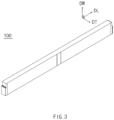
- FIG. 3 is a perspective view illustrating a logical cell according to Embodiment 1 of the present invention.
- FIG. 4a is an exploded perspective view illustrating the logical cell according to Embodiment 1 of the present invention.
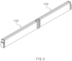
- FIG. 5 is a perspective view illustrating a state in which a case of the logical cell is removed according to Embodiment 1 of the present invention.
- a logical cell 100 includes a pouch cell assembly 110, a case 120, a side busbar frame assembly 130, an end plate 140, a side busbar 150, and a reinforcing plate 160.
- the logical cell 100 may mean a unit in which a plurality of pouch cells 111 or a pouch cell assembly 110 are gathered to be electrically connected to each other.
- the pouch cell assembly 110 is formed by arranging the plurality of pouch cells 111 in a thickness direction DT, and the case 120 is formed in a shape in which one side and other end thereof are opened so that the plurality of pouch cell assemblies 110 are accommodated in the case 120 in a longitudinal direction DL.
- the side busbar frame assembly 130 is coupled to the pouch cell assembly 110 at one side or other end of the case 120, and the end plate 140 is coupled to one side of the side busbar frame assembly 130 to cover one end or the other end, which is opened, of the case 120.
- the side busbar 150 is provided between the side busbar 150 and the end plate 140 and electrically connected to the pouch cell assembly 110 to transmit an output to the outside.
- the reinforcing plate 160 of the logical cell 100 is provided at one side of the end plate 140.
- the end plate 140 of the end plate 140 may mean an opposite side of the side of the end plate 140, which is coupled to the side busbar frame assembly 130.
- the reinforcing plate 160 may include a material that is capable of reinforcing rigidity of a side area corresponding to one side or other side of the logical cell 100, preferably aluminum.
- the pouch cells 111 may be arranged in the thickness direction DT to form the pouch cell assembly 110, and the plurality of pouch cell assemblies 110 may be accommodated in the longitudinal direction DL to form the logical cell 100 corresponding to a radical unit to improve easy of the handling of the cell compared to the pouch cell 111 inserted into the secondary battery module or the pack according to the related art. That is, in the previous process of the module of the secondary battery, modularization of the pouch cell 111 may be achieved and applied to the secondary battery pack having various structures and sizes.
- the secondary battery module may be arranged in the thickness direction DT to minimize an isolation cover and inter busbar, which are provided in the secondary battery pack, reduce a distance between the logical cells 100, and maximize space utilization inside the secondary battery pack, thereby optimizing a volume of the secondary battery pack and maximizing the energy density per unit volume.
- the reinforcing plate 160 may be additionally provided at one side of the end plate 140 to prevent a side that is vulnerable to an impact from being damaged and to improve safety of the secondary battery.
- the logical cell 100 may further include an insulating plate 190 provided between the end plate 140 and the reinforcing plate 160, and thus, the reinforcing plate 160 may be insulated so as not to be electrically connected to the pouch cell assembly 110 by the side busbar 150.
- the logical cell 100 includes a pouch cell assembly 110, a case 120, a center busbar frame assembly 230, and a center busbar 240.
- the pouch cell assembly 110 is formed by arranging a plurality of pouch cells 111 in a thickness direction DT, and the case 120 is formed in a shape in which one side and other end thereof are opened so that the plurality of pouch cell assemblies 110 are accommodated in the case 120 in a longitudinal direction DL.
- the center busbar frame assembly 230 is provided between the plurality of pouch cell assemblies 110, and the center busbar 240 is provided in the center busbar frame assembly 230 to electrically connect the plurality of pouch cell assemblies 110 to each other. That is, the logical cell 100 may mean a unit in which the plurality of pouch cells 111 or the pouch cell assembly 110 are gathered to be electrically connected to each other.
- the pouch cells 111 may be arranged in the thickness direction DT to form the pouch cell assembly 110, and the plurality of pouch cell assemblies 110 may be accommodated in the longitudinal direction DL to form the logical cell 100 corresponding to a radical unit to improve easy of the handling of the cell compared to the pouch cell 111 inserted into the secondary battery module or the pack according to the related art. That is, in the previous process of the module of the secondary battery, modularization of the pouch cell 111 may be achieved and applied to the secondary battery pack having various structures and sizes.
- the secondary battery module may be arranged in the thickness direction DT to minimize an isolation cover and inter busbar, which are provided in the secondary battery pack, reduce a distance between the logical cells 100, and maximize space utilization inside the secondary battery pack, thereby optimizing a volume of the secondary battery pack and maximizing the energy density per unit volume.
- the pouch cell assembly 110 is formed by gathering the plurality of pouch cells 111, and in the present invention, it is preferable that three pouch cells 111 are arranged side by side in the thickness direction DT, the longitudinal direction DL, and a width direction DW of the pouch cell 111 to form the pouch cell assembly 110.
- the pouch cell 111 may include a pouch made of a soft material and corresponding to an exterior, a plurality of electrode tabs drawn out from the electrode assembly, and a lead 112 protruding to the outside of the pouch.
- the pouch cell assembly 110 may include the lead 112 protruding from the pouch cell 111.
- the plurality of pouch cell assemblies 110 may be accommodated in the longitudinal direction DL, and in the present invention, it is preferable that two pouch cell assemblies 110 are accommodated in the longitudinal direction DL of the pouch cell assemblies 110.
- the case 120 may be formed in a shape of which one end and the other end are opened and may be covered by the end plate 140.
- the logical cell 100 according to the present invention may additionally secure the rigidity by being accommodated in the case 120 additionally provided in addition to the pouch of the pouch cell 111, and thus, the need to secure the rigidity in the pack unit may be reduced to simplify a structure and volume of the pack structure.
- an insulating sheet may be provided between the pouch cell 111 and the case 120 to achieve insulation.
- the case 120 may be integrally formed, but may be formed by coupling the first case 121 to the second case 122.
- the first case 121 may be formed in a recessed shape in which the pouch cell assembly 110 is accommodated
- the second case 122 is formed in a flat shape to be coupled to the first case 121 at one side of the first case 121.
- easy of manufacturing of the logical cell 100 may be improved.
- case 120 may be formed to correspond to a shape of a side surface of the end plate 140 at one end or the other end, which is opened.
- the shape of the side surface of the end plate 140 will be described in detail below.
- the pouch cell assembly 110 is formed by gathering the plurality of pouch cells 111, and in the present invention, it is preferable that two pouch cells 111 are arranged side by side in the thickness direction DT, the longitudinal direction DL, and the width direction DW of the pouch cell 111 to form the pouch cell assembly 110.
- the pouch cell 111 may include a pouch made of a soft material and corresponding to an exterior, a plurality of electrode tabs drawn out from the electrode assembly, and a lead 112 protruding to the outside of the pouch.
- the pouch cell assembly 110 may include the lead 112 protruding from the pouch cell 111.
- the plurality of pouch cell assemblies 110 may be accommodated in the longitudinal direction DL, and in the present invention, it is preferable that two pouch cell assemblies 110 are accommodated in the longitudinal direction DL of the pouch cell assemblies 110.
- the case 120 may be formed to have one end and the other end, which are opened, and thus may be covered by a front cover plate 260-1 and a rear cover plate 260-2 to be described later.
- the logical cell 100 according to the present invention may additionally secure the rigidity by being accommodated in the case 120 additionally provided in addition to the pouch of the pouch cell 111, and thus, the need to secure the rigidity in the pack unit may be reduced to simplify a structure and volume of the pack structure.
- an insulating sheet I may be provided between the pouch cell 111 and the case 120 to achieve insulation.
- the case 120 may be integrally formed, but may be formed by coupling the first case 121 to the second case 122.
- the first case 121 may be formed in a recessed shape in which the pouch cell assembly 110 is accommodated
- the second case 122 is formed in a flat shape to be coupled to the first case 121 at one side of the first case 121.
- easy of manufacturing of the logical cell 100 may be improved.
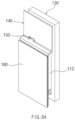
- FIG. 6a is a perspective view illustrating a state in which the side busbar is provided between the side busbar frame assembly and the end plate provided with the reinforcing plate of the logical cell according to Embodiment 1 of the present invention.
- FIG. 6b is an exploded perspective view illustrating the side busbar frame assembly, the reinforcing plate, the end plate, and the side busbar of the logical cell according to Embodiment 1 of the present invention.
- the side busbar frame assembly 130 may be an injection-molded insulating material coupled to the pouch cell assembly 110 at one end or the other end of the case 120.
- the pouch cell assembly 110 may include a lead 112 protruding from the pouch cell 111
- the side busbar frame assembly 130 may include a plurality of lead through-holes 131 into which the lead 112 of the pouch cell assembly 110 is inserted.
- a side busbar seating part 132 on which the side busbar 150 is seated may be formed on an area between the plurality of side lead through-holes 131.
- the side busbar seating part 132 may be formed in a recessed shape to allow the side busbar 150 to be seated thereon.
- the end plate 140 is coupled to one side of the side busbar frame assembly 130 to cover one end or the other end of the case 120, which are opened.
- one side of the side busbar frame assembly 130 may mean a side opposite to a side at which the side busbar frame assembly 130 is coupled to the pouch cell assembly 110 and also may mean the same direction as a direction facing the outside of the case 120.
- the covering of the one end or the other end of the case 120, which are opened may mean, for example, that one end or the other end are finished coincidentally so as not to generate a height difference with respect to an opened end surface of the case 120, but is not necessarily limited thereto, i.e., may mean that the pouch cell assembly 110 is finished at the end of the case so as not to be exposed to the outside of the case 120 even if the height difference is partially generated.
- the end plate 140 may include a first cover surface 141, a second cover surface 142, and a stepped surface 143.
- the first cover surface 141 may be coupled to be in contact with the side busbar frame assembly 130. That is, the first cover surface 141 may be a configuration that is disposed above the end plate 140 and allow the end plate 140 to be coupled to the side busbar frame assembly 130.
- the first cover surface 141 may be coupled to the side busbar frame assembly 130 in various manners and may be coupled to be in contact with the side busbar frame assembly 130 in, for example, a fitting manner.
- the second cover surface 142 may be provided to be spaced apart from the side busbar frame assembly 130 below the first cover surface 141, and the stepped surface 143 may connect the first cover surface 141 to the second cover surface 142.
- a stepped portion may be formed between the first cover surface 141 and the second cover surface 142, and the second cover surface 142 may be provided to be spaced apart from the side busbar frame assembly 130 by the stepped surface 143. That is, the shape of the side surface of the end plate 140 may be formed in a stepped shape by forming the stepped surface 143 between the upper first cover surface 141 and the lower second cover surface 142.
- the second cover surface 142 of the end plate 140 may be provided to be spaced apart from the side busbar frame assembly 130 by the stepped surface 143, thereby securing a space between the side busbar frame assembly 130 and the end plate 140.
- the lead 112 may be bent in this space and then be bonded to the side busbar 150 to serve as a buffer space when an external impact is applied.
- a busbar through-hole 141a passing through front and rear surfaces of the first cover surface 141 is formed in the first cover surface 141, and an upper area of the side busbar 150 may be bent to pass through the busbar through-hole 141a.
- the side busbar 150 provided between the end plate 140 and the side busbar frame assembly 130 may be exposed to serve as an output terminal.
- the number of busbar through-holes 141a is not limited.
- the busbar through-hole 141a may be formed in one, and when the side busbar frame assembly 130, the end plate 140, and the side busbar 150 are provided at only one side of the case 120, the busbar through-hole 141a may be formed in two so that the two side busbars 150 are exposed to one side to serve as output terminals, respectively.
- the busbar through-hole 141a may be formed not only on the first cover surface 141 but also on the second cover surface 142 or the stepped surface 143 as necessary.
- the side busbar 150 is provided between the side busbar frame assembly 130 and the end plate 140 and is electrically connected to the pouch cell assembly 110 to transmit an output to the outside.
- the side busbar 150 may be made of a conductor.
- the pouch cell assembly 110 includes the lead 112 protruding from the pouch cell 111 as described above, and the lead 112 may be electrically connected to the side busbar 150 by welding. That is, the leads 112 are formed at both sides of the pouch cell assembly 110 and may be electrically connected to the side busbar 150 and the center busbar 180 to be described later by welding.
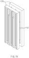
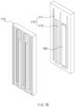
- FIG. 7a is a perspective view illustrating a pair of center busbar frame assemblies according to Embodiment 1 of the present invention.
- FIG. 7b is an exploded perspective view illustrating the pair of center busbar frame assemblies and the center busbar according to Embodiment 1 of the present invention.
- the logical cell 100 may further include a center busbar frame assembly 170 and a center busbar 180.
- a pair of center busbar frame assemblies 170 may be provided to face each other between the plurality of pouch cell assemblies 110. That is, each of the pair of center busbar frame assemblies 170 may be provided at an end of each pouch cell assembly 110 in the two pouch cell assemblies 110 accommodated in the longitudinal direction inside the case 120.
- the center busbar 180 may be provided in the center busbar frame assembly 170 to electrically connect the plurality of pouch cell assemblies 110 to each other.
- the pouch cell assembly 110 may include a lead 112 protruding from the pouch cell 111, and the center busbar frame assembly 170 may include a plurality of center lead through-holes 171 into which the lead 112 of the pouch cell assembly 110 is inserted.
- a center busbar seating part 172 on which the center busbar 180 is seated may be formed on an area between the plurality of center lead through-holes 171.
- the lead 112 may be bent while passing through the center lead through hole 171 so as to be electrically connected to the center busbar 180 of the center busbar seating part 172.
- Embodiment 2 of the present invention is different from embodiment 1 in that it is a secondary battery module including the logical cell 100 of embodiment 1.
- the contents that are duplicated with Embodiment 1 will be omitted as much as possible, and Embodiment 2 will be described with a focus on the differences. That is, it is obvious that the contents that are not described in Embodiment 2 may be regarded as the contents of Embodiment 1 if necessary.
- the secondary battery module according to Embodiment 2 of the present invention includes a logical cell 100, a circuit board, and a cover member.
- the logical cell 100 may be arranged so that a plurality of logical cells 100 are provided to overlap each other in a thickness direction.
- five logical cells 100 may be arranged in the thickness of the logical cell 100 to constitute one secondary battery module.
- the logical cell 100 may be understood as the same as the logical cell 100 according to Embodiment 1 and includes a pouch cell assembly 110 formed by arranging a plurality of pouch cells 111 in a thickness direction, a case 120 in which the plurality of pouch cell assemblies 110 are accommodated therein in the longitudinal direction and which has one end and the other end, which are opened, a side busbar frame assembly 130 coupled to the pouch cell assembly 110 at one end or the other end of the case 120, an end plate 140 coupled to one side of the side busbar frame assembly 130 to cover the one or the other open end of the case 120, a side busbar 150 provided between the side busbar frame assembly 130 and the end plate 140 and electrically connected to the pouch cell assembly 110 to transmit an output to the outside, and a reinforcing plate 160 provided at one side of the end plate 140.
- a pouch cell assembly 110 formed by arranging a plurality of pouch cells 111 in a thickness direction
- a case 120 in which the plurality of pouch cell assemblies 110 are accommodated therein in the longitudinal direction and
- the circuit board may be a printed circuit board (PCB), which electrically connects the side busbars 150 of the plurality of logical cells 100 to each other and simultaneously are integrally welded to the plurality of logical cells 100 at one side or the other side of each of the plurality of logical cells 100 so as to connect components that are necessary for controlling the secondary battery module.
- PCB printed circuit board
- the cover member may be integrally coupled to the plurality of logical cells 100 at one side or the other side of the plurality of logical cells 100 and may be coupled to cover the circuit board.
- the cover member may be a sensing component that protects the circuit board and the busbar from an external impact and simultaneously performs sensing.
- the secondary battery module since the logical cell 100 in which the pouch cell assembly 110 is accommodated in the longitudinal direction constitutes a module, the number of components for connecting the modules to each other inside the secondary battery pack may be minimized to maximize space utilization inside the pack and increase in energy density.
- a reinforcing plate is provided at one side or the other side of the case of the logical cell to intensively prevent a side portion that is vulnerable to the impact from being damaged, thereby improving safety of the secondary battery.
- Embodiment 3 of the present invention is different from Embodiments 1 and 2 in that it is a secondary battery pack including the logical cell of Embodiment 1 and the secondary battery module of Embodiment 2.
- the contents that are duplicated with Embodiments 1 and 2 will be omitted as much as possible, and Embodiment 3 will be described with a focus on the differences. That is, it is obvious that the contents that are not described in Embodiment 3 may be regarded as the contents of Embodiments 1 and 2 if necessary.
- FIG. 9 is a perspective view illustrating a secondary battery pack according to Embodiment 3 of the present invention.
- a secondary battery pack 1 according to Embodiment 3 of the present invention includes a pack case 20 and a secondary battery module 10.
- the pack case 20 may have an accommodation space therein and may be made of a material having rigidity to protect the secondary battery module 10 or the logical cell accommodated therein from an external impact.
- a shape and size of the pack case 20 may be variously formed as necessary, but a size of the internal accommodation space of the pack case 20 may be formed so that a length of at least one side corresponds to a length of the secondary battery module 10.
- the secondary battery module 10 is provided in the accommodation space of the pack case 20, and particularly is arranged in the accommodation space of the pack case 20 in a thickness direction of the secondary battery module 10.
- the secondary battery modules 10 are arranged in the lattice shape in the accommodation space inside the secondary battery pack 1, and thus, the structures for connecting the modules occupy the space inside the pack.
- the secondary battery module 10 constituted by the plurality of logical cells may be arranged in one direction, that is, a thickness direction, to improve space utilization inside the pack and improve energy density.
- a reinforcing plate may be provided at one side or the other side of the case to improve safety of the secondary battery.
- Embodiment 3 of the present invention may be understood as the same as the logical cell and the secondary battery module of Embodiments 1 and 2.
- FIG. 4b is an exploded perspective view illustrating a logical cell according to Embodiment 4 of the present invention.
- FIG. 10a is a perspective view illustrating a state in which a center busbar is provided in a center busbar frame assembly of the logical cell according to Embodiment 4 of the present invention.
- FIG. 14b is an exploded perspective view illustrating a rear busbar frame assembly, a rear cover plate, and a rear busbar of the logical cell according to Embodiment 4 of the present invention.
- FIG. 15 is an enlarged perspective view illustrating a state in which the center busbar frame assembly and the center busbar are provided between a plurality of pouch cell assemblies.
- a center busbar frame assembly 230 may include a pair of supports 231 and a pair of center busbar seating parts 232.
- the support 231 may be provided in a pair to support the pouch cell assembly 110 between the pouch cell assemblies 110 (see FIG. 4b ), and the center busbar mounting part 232 may be provided in a pair to be recessed in a direction perpendicular to the pair of supports 231 between the pair of supports 231.
- the supports 231 are provided in the pair may mean that the two supports 231 are formed to face opposite directions in the same line.
- the center busbar seating parts 232 are provided in the pair may mean that the two center busbar seating parts 232 are formed to face opposite directions in the same line.
- the center busbar 240 may be provided by being inserted into the center busbar seating part 232.
- the center busbar 240 may be made of a conductor to transmit electrical energy and may electrically connect the pouch cell assemblies 110, which are provided on both sides of the center busbar frame assembly 230 in a state of being inserted into the center busbar seating part 232, to each other.
- the pouch cell assembly 110 may include a lead 112 protruding from the pouch cell 111, and the lead 112 may be coupled to the center busbar 240 by welding to electrically connect the plurality of pouch cell assemblies 110 to each other.
- the center busbar seating part 232 may be formed to be recessed in a direction perpendicular to the support 231 formed to support the pouch cell assembly 110, and a busbar may be provided to be inserted into the center busbar seating part 232 so that the pouch cell assembly 110 is supported on the support 231, and also, the lead 112 formed to protrude in a longitudinal direction of the pouch cell assembly 110 is coupled to the busbar, thereby electrically connect the pouch cell assemblies 110 provided at both sides of the center busbar frame assembly 230 to each other.
- the logical cell 100 may further include a front busbar frame assembly 250-1, a front cover plate 260-1, and a front busbar 270-1.
- FIG. 12a is a perspective view illustrating a state in which a front busbar frame assembly, a front cover plate, and a front busbar of the logical cell are coupled to each other according to Embodiment 4 of the present invention.
- FIG. 12b is an exploded perspective view illustrating the front busbar frame assembly, the front cover plate, and the front busbar of the logical cell according to Embodiment 4 of the present invention.
- FIG. 13 is a view illustrating a state in which the front busbar frame assembly and the front busbar are coupled to a lead of the pouch cell assembly according to Embodiment 4 of the present invention.
- the front busbar frame assembly 250-1 may be an injection-molded product coupled to the pouch cell assembly 110 at one side of the case 120.
- one side of the case 120 may mean any one side of both sides of the case 120 in the longitudinal direction.
- a seating part of the front busbar 270-1, on which the front busbar 270-1 is seated, and a lead through-hole, through which the lead 112 passes to be in contact with the front busbar 270-1 may be formed in the front busbar frame assembly 250-1.
- the front cover plate 260-1 may be coupled to one side of the front busbar frame assembly 250-1 to cover opened one end of the case 120.
- one side of the front busbar frame assembly 250-1 may mean a side opposite to a side at which the front busbar frame assembly 250-1 is coupled to the pouch cell assembly 110 and also may mean a direction facing the outside of the case 120.
- the covering of the opened one end of the case 120 may mean, for example, that one end is finished coincidentally so as not to generate a height difference with respect to an opened end surface of the case 120, but is not necessarily limited thereto, i.e., may mean that the pouch cell assembly 110 is finished at the end of the case so as not to be exposed to the outside of the case 120 even if the height difference is partially generated.
- the front busbar 270-1 may further include a front busbar 270-1 provided between the front busbar frame assembly 250-1 and the front cover plate 260-1 and electrically connected to the pouch cell assembly 110 to transmit an output to the outside.
- the logical cell 100 according to the present invention may be provided with the front busbar 270-1 electrically connected to the pouch cell assembly 110 at one side of the case 120 to transmit an output to the outside in a single direction, thereby facilitate an arrangement and assembly inside the module and the pack.
- the pouch cell assembly 110 may include a lead 112 protruding from the pouch cell, and the lead 112 may be electrically connected to the front busbar 270-1 by welding to transmit an output to the outside. That is, the leads 112 are formed on both sides of the pouch cell assembly 110 and may be electrically connected to the center busbar and the front busbar 270-1 by the welding, respectively.
- the front cover plate 260-1 may be coupled to a lower portion of one side of the front busbar frame assembly 250-1.
- the front cover plate 260-1 may be coupled to the front busbar frame assembly 250-1 so that an upper portion of the front busbar 270-1 is exposed.
- a shape of a side surface of opened one end of the case 120 of the logical cell 100 according to the present invention may be formed to correspond to the of each of side surfaces of the front cover plate 260-1 and the front busbar frame assembly 250-1.
- the logical cell 100 may include a rear busbar frame assembly 250-2, a rear cover plate 260-2, and a rear busbar 270-2.
- FIG. 14a is a perspective view illustrating a state in which the rear busbar frame assembly and the rear cover plate of the logical cell are coupled to each other according to Embodiment 4 of the present invention.
- FIG. 14b is an exploded perspective view illustrating the rear busbar frame assembly, the rear cover plate, and the rear busbar of the logical cell according to Embodiment 4 of the present invention.
- the rear busbar frame assembly 250-2 may be an injection-molded product coupled to the pouch cell assembly 110 at the other side of the case 120.
- the other side of the case 120 may mean the other side opposite to the one side of both the sides of the case 120 in the longitudinal direction.
- a seating part of the rear busbar 270-2, on which the rear busbar 270-2 is seated, and a through-hole of the lead 112 through which the lead 112 passes to be in contact with the rear busbar 270-2 may be formed in the rear busbar frame assembly 250-2.
- the rear cover plate 260-2 may be coupled to one side of the rear busbar frame assembly 250-2 to cover the other end of the case 120, which is opened.
- One side of the rear busbar frame assembly 250-2 may mean a side opposite to a side at which the rear busbar frame assembly 250-2 is coupled to the pouch cell assembly 110 and also may mean a direction facing the outside of the case 120.
- the covering of the other end of the case 120, which is opened may mean, for example, that the other end is finished coincidentally so as not to generate a height difference with respect to an opened end surface of the case 120, but is not necessarily limited thereto, i.e., may mean that the pouch cell assembly 110 is finished at the end of the case so as not to be exposed to the outside of the case 120 even if the height difference is partially generated.
- the rear busbar 270-2 may be provided between the rear busbar frame assembly 250-2 and the rear cover plate 260-2 to electrically connect the pouch cells 111 of the pouch cell assembly 110 to each other. That is, the rear busbar 270-2 may serve to electrically connect the pouch cells 111 of the pouch cell assembly 110 to each other without transmitting the output of the pouch cell assembly 110 to the outside.
- the rear cover plate 260-2 may be coupled to one side of the rear busbar frame assembly 250-2 to cover the entire surface of the rear busbar 270-2. That is, the rear busbar 270-2 disposed at the other side of the case 120 may be provided between the rear busbar frame assembly 250-2 and the rear cover plate 260-2 and may not be exposed to the outside by the rear cover plate 260-2 that covers the entire surface of the rear busbar frame assembly 250-2. Therefore, the logical cell 100 according to the present invention may transmit the output from the front busbar 270-1 provided at the one side of the case to the outside in the single direction. As a result, in the logical cell 100 according to the present invention, since the output terminal due to the busbar may be unified in one direction (one side of the case) to facilitate the coupling of the components, the connection of the cells, and the formation of the module.
- Embodiment 5 of the present invention is different from embodiment 4 in that it is a secondary battery module 10 including the logical cell 100 of embodiment 4.
- the contents that are duplicated with Embodiment 4 will be omitted as much as possible, and Embodiment 5 will be described with a focus on the differences. That is, it is obvious that the contents that are not described in Embodiment 5 may be regarded as the contents of Embodiment 4 if necessary.
- a secondary battery module 10 according to Embodiment 5 of the present invention includes a logical cell 100, a circuit board 300, and a cover member 400.
- FIG. 15 is a perspective view illustrating a secondary battery module according to Embodiment 5 of the present invention.
- the logical cell 100 may be arranged so that a plurality of logical cells 100 are provided to overlap each other in a thickness direction. Preferably, five logical cells 100 may be arranged in the thickness of the logical cell 100 to constitute one secondary battery module 10.
- the logical cell 100 may be understood as the same as the logical cell 100 of Embodiment 4, and as illustrated in FIG.
- 4b may include a pouch cell assembly 110, in which a plurality of pouch cells 111 are arranged in a thickness direction, a case 120 in which the plurality of pouch cell assemblies 110 are accommodated in a longitudinal direction and of which one side and the other side are opened, a center busbar frame assembly 230 provided between the plurality of pouch cell assemblies 110, and a center busbar 240 provided in the center busbar frame assembly 230 to electrically connect the plurality of pouch cell assemblies 110 to each other.
- a pouch cell assembly 110 in which a plurality of pouch cells 111 are arranged in a thickness direction
- a case 120 in which the plurality of pouch cell assemblies 110 are accommodated in a longitudinal direction and of which one side and the other side are opened
- a center busbar frame assembly 230 provided between the plurality of pouch cell assemblies 110
- a center busbar 240 provided in the center busbar frame assembly 230 to electrically connect the plurality of pouch cell assemblies 110 to each other.
- the circuit board 300 may be a printed circuit board (PCB, 300), which electrically connects the front busbars 270-1 of the plurality of logical cells 100 to each other and simultaneously are integrally welded to the plurality of logical cells 100 at one side of each of the plurality of logical cells 100 so as to connect components that are necessary for controlling the secondary battery module 10.
- PCB printed circuit board
- cover member 400 may be integrally coupled to the plurality of logical cells 100 at the one side of the plurality of logical cells 100 and may be coupled to cover the circuit board 300.
- the cover member 400 may be a sensing component that protects the circuit board 300 and the busbar from an external impact and performs sensing.
- the secondary battery module 10 since the logical cell 100 in which the pouch cell assembly 110 is accommodated in the longitudinal direction constitutes a module, the number of components for connecting the modules to each other inside the secondary battery pack may be minimized to maximize space utilization inside the pack and increase in energy density.
- the logical cell 100 may further include a front busbar frame assembly 250-1 coupled to the pouch cell assembly 110 at one side of the case 120, a front cover plate 260-1 coupled to one side of the front busbar frame assembly 250-1 to cover the opened one end of the case 120, and a front busbar 270-1 provided between the front busbar frame assembly 250-1 and the front cover plate 260-1 and electrically connected to the pouch cell assembly 110 to transmit an output to the outside.
- the circuit board 300 may be integrally welded to the front busbar 270-1 of the plurality of logical cells 100.
- the logical cell 100 of the secondary battery module 10 may include the front busbar 270-1 electrically connected to the pouch cell assembly 110 at the one side of the case 120 as described above.
- the arrangement and assembly inside the pack may be easy, the structure may be simplified to improve energy density inside the secondary battery pack.
- Embodiment 6 of the present invention is different from Embodiments 4 and 5 in that it is a secondary battery pack 1 including the logical cell 100 of Embodiment 4 and the secondary battery module 10 of Embodiment 5.
- the contents that are duplicated with Embodiments 4 and 5 will be omitted as much as possible, and Embodiment 6 will be described with a focus on the differences. That is, it is obvious that the contents that are not described in Embodiment 6 may be regarded as the contents of Embodiments 4 and 5 if necessary.
- the secondary battery pack 1 according to Embodiment 6 of the present invention includes a pack case 20 and a secondary battery module 10.
- FIG. 12 is a perspective view illustrating a secondary battery pack according to Embodiment 6 of the present invention.
- the pack case 20 may have an accommodation space therein and may be made of a material having rigidity to protect the secondary battery module 10 or the logical cell 100 accommodated therein from an external impact.
- a shape and size of the pack case 20 may be variously formed as necessary, but a size of the internal accommodation space of the pack case 20 may be formed so that a length of at least one side corresponds to a length of the secondary battery module 10.
- the secondary battery module 10 is provided in the accommodation space of the pack case 20, and particularly is arranged in the accommodation space of the pack case 20 in a thickness direction of the secondary battery module 10.
- the secondary battery modules 10 are arranged in the lattice shape in the accommodation space inside the secondary battery pack 1, and thus, the structures for connecting the modules occupy the space inside the pack.
- the secondary battery module 10 constituted by the plurality of logical cells 100 may be arranged in one direction, that is, a thickness direction, to improve space utilization inside the pack and improve energy density.
Landscapes
- Chemical & Material Sciences (AREA)
- Chemical Kinetics & Catalysis (AREA)
- Electrochemistry (AREA)
- General Chemical & Material Sciences (AREA)
- Engineering & Computer Science (AREA)
- Microelectronics & Electronic Packaging (AREA)
- Manufacturing & Machinery (AREA)
- Battery Mounting, Suspending (AREA)
- Connection Of Batteries Or Terminals (AREA)
- Sealing Battery Cases Or Jackets (AREA)
Abstract
Description
- The present application claims the benefit of the priority of
Korean Patent Application Nos. 10-2021-0187826, filed on December 24, 2021 10-2021-0187827, filed on December 24, 2021 - The present invention relates to a logical cell, a secondary battery module, and a secondary battery pack including the same.
- A secondary battery refers to a battery that is chargeable and dischargeable, unlike a primary battery that is not charged, and examples of the secondary battery may include a nickel cadmium battery, a nickel hydrogen battery, a lithium ion battery, and a lithium ion polymer battery. Such a secondary battery is being applied to be used in small-sized products such as digital cameras, notebooks, mobile phones, PDAs, E-bikes, and the like as well as large-sized products requiring high power such as electric vehicles and hybrid vehicles, power storage devices for storing surplus power or renewable energy, and backup power storage devices.
- Such a secondary battery is classified into a pouch-type secondary battery and a can type secondary battery according to a material of a battery case accommodating an electrode assembly. In the pouch-type secondary battery, the electrode assembly is accommodated in a pouch made of a flexible polymer material having a variable shape. In addition, in the can-type secondary battery, an electrode assembly is accommodated in a case made of a metal or plastic material having a predetermined shape.
- In addition, the secondary battery may be constituted by cells, modules, and packs according to a unit for collecting secondary batteries. The cell may be a basic unit of the secondary battery that is capable of being used by charging electrical energy, which may be the above-described pouch-type secondary battery or the can-type secondary battery. The secondary battery module refers to an assembly, in which the predetermined number of cells are bundled or are put in a frame so as to protected against an external impact, heat, and vibration, and the pack may be a final form of a battery system and be completed by mounting various control and protection systems such as BMS, a cooling system, and the like, on the secondary battery module.
-
FIG. 1 is a perspective view illustrating a secondary battery module according to a related art.FIG. 2 is a perspective view illustrating a secondary battery pack according to the related art. Referring toFIGS. 1 and2 , in the secondary battery module and pack according to the related art, cells are arranged in a thickness direction of the cell to constitute the module, and the secondary battery module is disposed in a lattice shape inside a pack case. However, in this manner, a lot of spaces and components A for disposing or connecting the secondary battery module as the lattice shape are required, and particularly, an end plate, an isolation cover, and a module and an inter busbar for connecting the modules to each other are additionally required to increase in distance between the cells in the pack unit. This not only decreases in energy density per unit volume in the pack unit, but also increases in volume of the pack to increase in space occupied by the battery in a final product. - As a result, development of more simplified unit cell, in which space utilization inside the secondary battery pack is maximized, and energy density increases, and simultaneously, rigidity thereof is reinforced to secure safety of the secondary battery, a secondary battery module including the same, and a secondary battery pack are required.
- The present invention is invented to solve the above problem, and an object of the present invention is to provide a logical cell, in which a pouch cell assembly in which a plurality of pouch cells are arranged is accommodated inside a case in a longitudinal direction to form a logical cell, and a reinforcing plate is provided at one side or the other side of the case to reinforce rigidity, thereby facilitating handling of the pouch cell and maximizing space utilization, and simultaneously, preventing the side that is vulnerable to an impact from being damaged so that the secondary battery is improved in safety, a secondary battery module, and a secondary battery pack including the same.
- In addition, an object of the present invention is to provide a logical cell, in which a pouch cell assembly in which a plurality of pouch cells are arranged is accommodated inside a case in a longitudinal direction, and the pouch cell assemblies are electrically connected to each other by using a center busbar assembly and a center busbar therebetween to form a logical cell, thereby facilitating handling of the pouch cell and maximizing space utilization, a secondary battery module, and a secondary battery pack including the same.
- A logical cell according to an embodiment of the present invention include a pouch cell assembly in which a plurality of pouch cells are arranged in a thickness direction, a case in which the plurality of pouch cell assemblies are accommodated in a longitudinal direction, wherein one end and the other end of the case are opened, a side busbar frame assembly coupled to the pouch cell assembly at the one side or the other side of the case, an end plate coupled to one side of the side busbar frame assembly to cover the one side or the other side of the case, which are opened, a side busbar provided between the side busbar frame assembly and the end plate and electrically connected to the pouch cell assembly to transmit an output to the outside, and a reinforcing plate provided at one side of the end plate.
- A logical cell according to an embodiment of the present invention includes a pouch cell assembly in which a plurality of pouch cells are arranged in the thickness direction, a case in which the plurality of pouch cell assemblies are accommodated in a longitudinal direction, wherein one end and the other end of the case are opened, a center busbar frame assembly provided between the plurality of pouch cell assemblies, and a center busbar provided in the center busbar frame assembly to electrically connect the plurality of pouch cell assemblies to each other.
- In the logical cell according to the present invention, the pouch cell assembly in which a plurality of pouch cells are arranged may be accommodated inside the case in the longitudinal direction to form the logical cell, and the reinforcing plate may be provided at one side or the other side of the case to reinforce rigidity, thereby facilitating the handling of the pouch cell and maximizing the space utilization, and simultaneously, preventing the side that is vulnerable to the impact from being damaged so that the secondary battery is improved in safety, a secondary battery module, and a secondary battery pack including the same.
- The logical cell according to the present invention may include the pouch cell assembly in which the plurality of pouch cells are arranged in the thickness direction, the case in which the plurality of pouch cell assemblies are accommodated in the longitudinal direction and of which one side and the other side are opened, the center busbar frame assembly provided between the plurality of pouch cell assemblies, and the center busbar provided in the center busbar frame assembly and electrically connecting the plurality of pouch cell assemblies to each other, and thus, the handling of the pouch cell inside the module or the pack may be facilitated, and the space utilization and the energy density within the pack may be maximized.
-
-
FIG. 1 is a perspective view illustrating a secondary battery module according to a related art. -
FIG. 2 is a perspective view illustrating a secondary battery pack according to the related art. -
FIG. 3 is a perspective view illustrating a logical cell according toEmbodiment 1 of the present invention. -
FIG. 4a andFIG. 4b are an exploded perspective view illustrating the logical cell according toEmbodiment 1 of the present invention. -
FIG. 5 is a perspective view illustrating a state in which a case of the logical cell is removed according toEmbodiment 1 of the present invention. -
FIG. 6a is a perspective view illustrating a state in which a side busbar is provided between a side busbar frame assembly and an end plate provided with a reinforcing plate of the logical cell according toEmbodiment 1 of the present invention. -
FIG. 6b is an exploded perspective view illustrating the side busbar frame assembly, the reinforcing plate, the end plate, and a side busbar of the logical cell according toEmbodiment 1 of the present invention. -
FIG. 7a is a perspective view illustrating a pair of center busbar frame assemblies according toEmbodiment 1 of the present invention. -
FIG. 7b is an exploded perspective view illustrating the pair of center busbar frame assemblies and the center busbar according toEmbodiment 1 of the present invention. -
FIG. 8 is a perspective view illustrating an insulating plate provided between the end plate and the reinforcing plate of the logical cell according toEmbodiment 1 of the present invention. -
FIG. 9 is a perspective view illustrating a secondary battery pack according to Embodiment 3 of the present invention. -
FIG. 10a is a perspective view illustrating a state in which a center busbar is provided in a center busbar frame assembly of a logical cell according to Embodiment 4 of the present invention. -
FIG. 10b is an exploded perspective view illustrating the center busbar frame assembly and the center busbar of the logical cell according to Embodiment 4 of the present invention. -
FIG. 11 is an enlarged perspective view illustrating a state in which the center busbar frame assembly and the center busbar are provided between a plurality of pouch cell assemblies. -
FIG. 12a is a perspective view illustrating a state in which a front busbar frame assembly, a front cover plate, and a front busbar of the logical cell are coupled to each other according to Embodiment 4 of the present invention. -
FIG. 12b is an exploded perspective view illustrating the front busbar frame assembly, the front cover plate, and the front busbar of the logical cell according to Embodiment 4 of the present invention. -
FIG. 13 is a view illustrating a state in which the front busbar frame assembly and the front busbar are coupled to a lead of the pouch cell assembly according to Embodiment 4 of the present invention. -
FIG. 14a is a perspective view illustrating a state in which a rear busbar frame assembly and a rear cover plate of the logical cell are coupled to each other according to Embodiment 4 of the present invention. -
FIG. 14b is an exploded perspective view illustrating the rear busbar frame assembly, the rear cover plate, and the rear busbar of the logical cell according to Embodiment 4 of the present invention. -
FIG. 15 is a perspective view illustrating a secondary battery module according to Embodiment 5 of the present invention. - Hereinafter, preferred embodiments of the present invention will be described in detail with reference to the accompanying drawings so that those of ordinary skill in the art can easily carry out the present invention. However, the present invention may be implemented in several different forms and is not limited or restricted by the following examples.
- In order to clearly explain the present invention, detailed descriptions of portions that are irrelevant to the description or related known technologies that may unnecessarily obscure the gist of the present invention have been omitted, and in the present specification, reference symbols are added to components in each drawing. In this case, the same or similar reference numerals are assigned to the same or similar elements throughout the specification.
- Also, terms or words used in this specification and claims should not be restrictively interpreted as ordinary meanings or dictionary-based meanings, but should be interpreted as meanings and concepts conforming to the scope of the present invention on the basis of the principle that an inventor can properly define the concept of a term to describe and explain his or her invention in the best ways.
-
FIG. 3 is a perspective view illustrating a logical cell according toEmbodiment 1 of the present invention.FIG. 4a is an exploded perspective view illustrating the logical cell according toEmbodiment 1 of the present invention.FIG. 5 is a perspective view illustrating a state in which a case of the logical cell is removed according toEmbodiment 1 of the present invention. - Referring to
FIGS. 3 ,FIG. 4a , andFIG. 5 , alogical cell 100 according toEmbodiment 1 of the present invention includes apouch cell assembly 110, acase 120, a sidebusbar frame assembly 130, anend plate 140, aside busbar 150, and a reinforcingplate 160. Here, thelogical cell 100 may mean a unit in which a plurality ofpouch cells 111 or apouch cell assembly 110 are gathered to be electrically connected to each other. - First, the
pouch cell assembly 110 is formed by arranging the plurality ofpouch cells 111 in a thickness direction DT, and thecase 120 is formed in a shape in which one side and other end thereof are opened so that the plurality ofpouch cell assemblies 110 are accommodated in thecase 120 in a longitudinal direction DL. The sidebusbar frame assembly 130 is coupled to thepouch cell assembly 110 at one side or other end of thecase 120, and theend plate 140 is coupled to one side of the sidebusbar frame assembly 130 to cover one end or the other end, which is opened, of thecase 120. Theside busbar 150 is provided between theside busbar 150 and theend plate 140 and electrically connected to thepouch cell assembly 110 to transmit an output to the outside. - In addition, the reinforcing
plate 160 of thelogical cell 100 according to the present invention is provided at one side of theend plate 140. Here, theend plate 140 of theend plate 140 may mean an opposite side of the side of theend plate 140, which is coupled to the sidebusbar frame assembly 130. The reinforcingplate 160 may include a material that is capable of reinforcing rigidity of a side area corresponding to one side or other side of thelogical cell 100, preferably aluminum. - As described above, according to the present invention, the
pouch cells 111 may be arranged in the thickness direction DT to form thepouch cell assembly 110, and the plurality ofpouch cell assemblies 110 may be accommodated in the longitudinal direction DL to form thelogical cell 100 corresponding to a radical unit to improve easy of the handling of the cell compared to thepouch cell 111 inserted into the secondary battery module or the pack according to the related art. That is, in the previous process of the module of the secondary battery, modularization of thepouch cell 111 may be achieved and applied to the secondary battery pack having various structures and sizes. - In addition, in the process of arranging the secondary battery module inside the secondary battery pack, the secondary battery module may be arranged in the thickness direction DT to minimize an isolation cover and inter busbar, which are provided in the secondary battery pack, reduce a distance between the
logical cells 100, and maximize space utilization inside the secondary battery pack, thereby optimizing a volume of the secondary battery pack and maximizing the energy density per unit volume. - In addition, the reinforcing
plate 160 may be additionally provided at one side of theend plate 140 to prevent a side that is vulnerable to an impact from being damaged and to improve safety of the secondary battery. - As illustrated in
FIG. 8 , thelogical cell 100 according to the present invention may further include an insulatingplate 190 provided between theend plate 140 and the reinforcingplate 160, and thus, the reinforcingplate 160 may be insulated so as not to be electrically connected to thepouch cell assembly 110 by theside busbar 150. - Referring to
FIGS. 3 ,4b , and5 , thelogical cell 100 according to Embodiment 4 of the present invention includes apouch cell assembly 110, acase 120, a centerbusbar frame assembly 230, and acenter busbar 240. - First, the
pouch cell assembly 110 is formed by arranging a plurality ofpouch cells 111 in a thickness direction DT, and thecase 120 is formed in a shape in which one side and other end thereof are opened so that the plurality ofpouch cell assemblies 110 are accommodated in thecase 120 in a longitudinal direction DL. In addition, the centerbusbar frame assembly 230 is provided between the plurality ofpouch cell assemblies 110, and thecenter busbar 240 is provided in the centerbusbar frame assembly 230 to electrically connect the plurality ofpouch cell assemblies 110 to each other. That is, thelogical cell 100 may mean a unit in which the plurality ofpouch cells 111 or thepouch cell assembly 110 are gathered to be electrically connected to each other. - As described above, according to the present invention, the
pouch cells 111 may be arranged in the thickness direction DT to form thepouch cell assembly 110, and the plurality ofpouch cell assemblies 110 may be accommodated in the longitudinal direction DL to form thelogical cell 100 corresponding to a radical unit to improve easy of the handling of the cell compared to thepouch cell 111 inserted into the secondary battery module or the pack according to the related art. That is, in the previous process of the module of the secondary battery, modularization of thepouch cell 111 may be achieved and applied to the secondary battery pack having various structures and sizes. - In addition, in the process of arranging the secondary battery module inside the secondary battery pack, the secondary battery module may be arranged in the thickness direction DT to minimize an isolation cover and inter busbar, which are provided in the secondary battery pack, reduce a distance between the
logical cells 100, and maximize space utilization inside the secondary battery pack, thereby optimizing a volume of the secondary battery pack and maximizing the energy density per unit volume. - Hereinafter, each configuration of the
logical cell 100 according to the present invention will be described in detail with reference toFIGS. 3 to 7 . - First, referring to
FIGS. 3 ,4a and5 , thepouch cell assembly 110 is formed by gathering the plurality ofpouch cells 111, and in the present invention, it is preferable that threepouch cells 111 are arranged side by side in the thickness direction DT, the longitudinal direction DL, and a width direction DW of thepouch cell 111 to form thepouch cell assembly 110. Thepouch cell 111 may include a pouch made of a soft material and corresponding to an exterior, a plurality of electrode tabs drawn out from the electrode assembly, and a lead 112 protruding to the outside of the pouch. Thus, thepouch cell assembly 110 may include thelead 112 protruding from thepouch cell 111. - Next, in the
case 120, the plurality ofpouch cell assemblies 110 may be accommodated in the longitudinal direction DL, and in the present invention, it is preferable that twopouch cell assemblies 110 are accommodated in the longitudinal direction DL of thepouch cell assemblies 110. In addition, thecase 120 may be formed in a shape of which one end and the other end are opened and may be covered by theend plate 140. As described above, thelogical cell 100 according to the present invention may additionally secure the rigidity by being accommodated in thecase 120 additionally provided in addition to the pouch of thepouch cell 111, and thus, the need to secure the rigidity in the pack unit may be reduced to simplify a structure and volume of the pack structure. In addition, an insulating sheet may be provided between thepouch cell 111 and thecase 120 to achieve insulation. - The
case 120 may be integrally formed, but may be formed by coupling thefirst case 121 to thesecond case 122. Explaining this structure in detail, thefirst case 121 may be formed in a recessed shape in which thepouch cell assembly 110 is accommodated, and thesecond case 122 is formed in a flat shape to be coupled to thefirst case 121 at one side of thefirst case 121. As described above, when thecase 120 is formed in the form that includes thefirst case 121 and thesecond case 122 to couple thesecond case 122 to thefirst case 121, easy of manufacturing of thelogical cell 100 may be improved. - In addition, the
case 120 may be formed to correspond to a shape of a side surface of theend plate 140 at one end or the other end, which is opened. The shape of the side surface of theend plate 140 will be described in detail below. - Referring to
FIGS. 3 ,4a and5 , thepouch cell assembly 110 is formed by gathering the plurality ofpouch cells 111, and in the present invention, it is preferable that twopouch cells 111 are arranged side by side in the thickness direction DT, the longitudinal direction DL, and the width direction DW of thepouch cell 111 to form thepouch cell assembly 110. Thepouch cell 111 may include a pouch made of a soft material and corresponding to an exterior, a plurality of electrode tabs drawn out from the electrode assembly, and a lead 112 protruding to the outside of the pouch. Thus, thepouch cell assembly 110 may include thelead 112 protruding from thepouch cell 111. - Next, in the
case 120, the plurality ofpouch cell assemblies 110 may be accommodated in the longitudinal direction DL, and in the present invention, it is preferable that twopouch cell assemblies 110 are accommodated in the longitudinal direction DL of thepouch cell assemblies 110. In addition, thecase 120 may be formed to have one end and the other end, which are opened, and thus may be covered by a front cover plate 260-1 and a rear cover plate 260-2 to be described later. As described above, thelogical cell 100 according to the present invention may additionally secure the rigidity by being accommodated in thecase 120 additionally provided in addition to the pouch of thepouch cell 111, and thus, the need to secure the rigidity in the pack unit may be reduced to simplify a structure and volume of the pack structure. In addition, an insulating sheet I may be provided between thepouch cell 111 and thecase 120 to achieve insulation. - The
case 120 may be integrally formed, but may be formed by coupling thefirst case 121 to thesecond case 122. Explaining this structure in detail, thefirst case 121 may be formed in a recessed shape in which thepouch cell assembly 110 is accommodated, and thesecond case 122 is formed in a flat shape to be coupled to thefirst case 121 at one side of thefirst case 121. As described above, when thecase 120 is formed in the form that includes thefirst case 121 and thesecond case 122 to couple thesecond case 122 to thefirst case 121, easy of manufacturing of thelogical cell 100 may be improved. - Next, the side
busbar frame assembly 130 will be described with reference toFIGS. 4a ,6a and6b .FIG. 6a is a perspective view illustrating a state in which the side busbar is provided between the side busbar frame assembly and the end plate provided with the reinforcing plate of the logical cell according toEmbodiment 1 of the present invention.FIG. 6b is an exploded perspective view illustrating the side busbar frame assembly, the reinforcing plate, the end plate, and the side busbar of the logical cell according toEmbodiment 1 of the present invention. - The side
busbar frame assembly 130 may be an injection-molded insulating material coupled to thepouch cell assembly 110 at one end or the other end of thecase 120. Also, as described above, thepouch cell assembly 110 may include a lead 112 protruding from thepouch cell 111, and the sidebusbar frame assembly 130 may include a plurality of lead through-holes 131 into which thelead 112 of thepouch cell assembly 110 is inserted. In addition, a sidebusbar seating part 132 on which theside busbar 150 is seated may be formed on an area between the plurality of side lead through-holes 131. The sidebusbar seating part 132 may be formed in a recessed shape to allow theside busbar 150 to be seated thereon. - Subsequently, the
end plate 140 will be described with reference toFIGS. 4a and6a and6b . Theend plate 140 is coupled to one side of the sidebusbar frame assembly 130 to cover one end or the other end of thecase 120, which are opened. Here, one side of the sidebusbar frame assembly 130 may mean a side opposite to a side at which the sidebusbar frame assembly 130 is coupled to thepouch cell assembly 110 and also may mean the same direction as a direction facing the outside of thecase 120. In addition, the covering of the one end or the other end of thecase 120, which are opened, may mean, for example, that one end or the other end are finished coincidentally so as not to generate a height difference with respect to an opened end surface of thecase 120, but is not necessarily limited thereto, i.e., may mean that thepouch cell assembly 110 is finished at the end of the case so as not to be exposed to the outside of thecase 120 even if the height difference is partially generated. - Referring to the configuration of the
end plate 140 in more detail with reference toFIG. 6b , theend plate 140 may include afirst cover surface 141, asecond cover surface 142, and a stepped surface 143. - First, the
first cover surface 141 may be coupled to be in contact with the sidebusbar frame assembly 130. That is, thefirst cover surface 141 may be a configuration that is disposed above theend plate 140 and allow theend plate 140 to be coupled to the sidebusbar frame assembly 130. Thefirst cover surface 141 may be coupled to the sidebusbar frame assembly 130 in various manners and may be coupled to be in contact with the sidebusbar frame assembly 130 in, for example, a fitting manner. - The
second cover surface 142 may be provided to be spaced apart from the sidebusbar frame assembly 130 below thefirst cover surface 141, and the stepped surface 143 may connect thefirst cover surface 141 to thesecond cover surface 142. Here, a stepped portion may be formed between thefirst cover surface 141 and thesecond cover surface 142, and thesecond cover surface 142 may be provided to be spaced apart from the sidebusbar frame assembly 130 by the stepped surface 143. That is, the shape of the side surface of theend plate 140 may be formed in a stepped shape by forming the stepped surface 143 between the upperfirst cover surface 141 and the lowersecond cover surface 142. - As described above, the
second cover surface 142 of theend plate 140 may be provided to be spaced apart from the sidebusbar frame assembly 130 by the stepped surface 143, thereby securing a space between the sidebusbar frame assembly 130 and theend plate 140. Here, thelead 112 may be bent in this space and then be bonded to theside busbar 150 to serve as a buffer space when an external impact is applied. - In addition, a busbar through-
hole 141a passing through front and rear surfaces of thefirst cover surface 141 is formed in thefirst cover surface 141, and an upper area of theside busbar 150 may be bent to pass through the busbar through-hole 141a. As a result, theside busbar 150 provided between theend plate 140 and the sidebusbar frame assembly 130 may be exposed to serve as an output terminal. The number of busbar through-holes 141a is not limited. For example, when the sidebusbar frame assembly 130, theend plate 140, and theside busbar 150 are provided at both sides of thecase 120, the busbar through-hole 141a may be formed in one, and when the sidebusbar frame assembly 130, theend plate 140, and theside busbar 150 are provided at only one side of thecase 120, the busbar through-hole 141a may be formed in two so that the twoside busbars 150 are exposed to one side to serve as output terminals, respectively. In addition, the busbar through-hole 141a may be formed not only on thefirst cover surface 141 but also on thesecond cover surface 142 or the stepped surface 143 as necessary. - The
side busbar 150 is provided between the sidebusbar frame assembly 130 and theend plate 140 and is electrically connected to thepouch cell assembly 110 to transmit an output to the outside. For this, theside busbar 150 may be made of a conductor. In addition, thepouch cell assembly 110 includes thelead 112 protruding from thepouch cell 111 as described above, and thelead 112 may be electrically connected to theside busbar 150 by welding. That is, theleads 112 are formed at both sides of thepouch cell assembly 110 and may be electrically connected to theside busbar 150 and thecenter busbar 180 to be described later by welding. -
FIG. 7a is a perspective view illustrating a pair of center busbar frame assemblies according toEmbodiment 1 of the present invention.FIG. 7b is an exploded perspective view illustrating the pair of center busbar frame assemblies and the center busbar according toEmbodiment 1 of the present invention. - Referring to
FIGS. 4a ,7a , and7b , thelogical cell 100 according to the present invention may further include a centerbusbar frame assembly 170 and acenter busbar 180. First, a pair of centerbusbar frame assemblies 170 may be provided to face each other between the plurality ofpouch cell assemblies 110. That is, each of the pair of centerbusbar frame assemblies 170 may be provided at an end of eachpouch cell assembly 110 in the twopouch cell assemblies 110 accommodated in the longitudinal direction inside thecase 120. Thecenter busbar 180 may be provided in the centerbusbar frame assembly 170 to electrically connect the plurality ofpouch cell assemblies 110 to each other. - Also, as described above in more detail, the
pouch cell assembly 110 may include a lead 112 protruding from thepouch cell 111, and the centerbusbar frame assembly 170 may include a plurality of center lead through-holes 171 into which thelead 112 of thepouch cell assembly 110 is inserted. In addition, a centerbusbar seating part 172 on which thecenter busbar 180 is seated may be formed on an area between the plurality of center lead through-holes 171. As a result, thelead 112 may be bent while passing through the center lead throughhole 171 so as to be electrically connected to thecenter busbar 180 of the centerbusbar seating part 172. - Embodiment 2 of the present invention is different from
embodiment 1 in that it is a secondary battery module including thelogical cell 100 ofembodiment 1. The contents that are duplicated withEmbodiment 1 will be omitted as much as possible, and Embodiment 2 will be described with a focus on the differences. That is, it is obvious that the contents that are not described in Embodiment 2 may be regarded as the contents ofEmbodiment 1 if necessary. - The secondary battery module according to Embodiment 2 of the present invention includes a
logical cell 100, a circuit board, and a cover member. - First, referring to
FIG. 4a , in the secondary battery module according to the present invention, thelogical cell 100 may be arranged so that a plurality oflogical cells 100 are provided to overlap each other in a thickness direction. Preferably, fivelogical cells 100 may be arranged in the thickness of thelogical cell 100 to constitute one secondary battery module. Here, thelogical cell 100 may be understood as the same as thelogical cell 100 according toEmbodiment 1 and includes apouch cell assembly 110 formed by arranging a plurality ofpouch cells 111 in a thickness direction, acase 120 in which the plurality ofpouch cell assemblies 110 are accommodated therein in the longitudinal direction and which has one end and the other end, which are opened, a sidebusbar frame assembly 130 coupled to thepouch cell assembly 110 at one end or the other end of thecase 120, anend plate 140 coupled to one side of the sidebusbar frame assembly 130 to cover the one or the other open end of thecase 120, aside busbar 150 provided between the sidebusbar frame assembly 130 and theend plate 140 and electrically connected to thepouch cell assembly 110 to transmit an output to the outside, and a reinforcingplate 160 provided at one side of theend plate 140. - The circuit board may be a printed circuit board (PCB), which electrically connects the
side busbars 150 of the plurality oflogical cells 100 to each other and simultaneously are integrally welded to the plurality oflogical cells 100 at one side or the other side of each of the plurality oflogical cells 100 so as to connect components that are necessary for controlling the secondary battery module. - In addition, the cover member may be integrally coupled to the plurality of
logical cells 100 at one side or the other side of the plurality oflogical cells 100 and may be coupled to cover the circuit board. The cover member may be a sensing component that protects the circuit board and the busbar from an external impact and simultaneously performs sensing. - As described above, in the secondary battery module according to the present invention, since the
logical cell 100 in which thepouch cell assembly 110 is accommodated in the longitudinal direction constitutes a module, the number of components for connecting the modules to each other inside the secondary battery pack may be minimized to maximize space utilization inside the pack and increase in energy density. - In addition, while minimizing a structure in the secondary battery pack, a reinforcing plate is provided at one side or the other side of the case of the logical cell to intensively prevent a side portion that is vulnerable to the impact from being damaged, thereby improving safety of the secondary battery.
- In addition, the detailed configuration of the
logical cell 100 and the resulting effect, which are not separately described in Embodiment 2 of the present invention, may be understood as the same as thelogical cell 100 ofEmbodiment 1. - Embodiment 3 of the present invention is different from
Embodiments 1 and 2 in that it is a secondary battery pack including the logical cell ofEmbodiment 1 and the secondary battery module of Embodiment 2. The contents that are duplicated withEmbodiments 1 and 2 will be omitted as much as possible, and Embodiment 3 will be described with a focus on the differences. That is, it is obvious that the contents that are not described in Embodiment 3 may be regarded as the contents ofEmbodiments 1 and 2 if necessary. -
FIG. 9 is a perspective view illustrating a secondary battery pack according to Embodiment 3 of the present invention. Referring toFIG. 9 , asecondary battery pack 1 according to Embodiment 3 of the present invention includes apack case 20 and asecondary battery module 10. - The
pack case 20 may have an accommodation space therein and may be made of a material having rigidity to protect thesecondary battery module 10 or the logical cell accommodated therein from an external impact. A shape and size of thepack case 20 may be variously formed as necessary, but a size of the internal accommodation space of thepack case 20 may be formed so that a length of at least one side corresponds to a length of thesecondary battery module 10. In addition, thesecondary battery module 10 is provided in the accommodation space of thepack case 20, and particularly is arranged in the accommodation space of thepack case 20 in a thickness direction of thesecondary battery module 10. - According to the related art, the
secondary battery modules 10 are arranged in the lattice shape in the accommodation space inside thesecondary battery pack 1, and thus, the structures for connecting the modules occupy the space inside the pack. On the other hand, according to the present invention, thesecondary battery module 10 constituted by the plurality of logical cells may be arranged in one direction, that is, a thickness direction, to improve space utilization inside the pack and improve energy density. In addition, in order to reinforce the rigidity of a side area of the logical cell that is vulnerable to breakage while minimizing the number of structures inside the secondary battery pack, a reinforcing plate may be provided at one side or the other side of the case to improve safety of the secondary battery. - In addition, the detailed configurations of the logical cell and the secondary battery module and the resulting effects, which are not separately described in Embodiment 3 of the present invention, may be understood as the same as the logical cell and the secondary battery module of
Embodiments 1 and 2. - While the embodiments of the present invention have been described with reference to the specific embodiments, it will be apparent to those skilled in the art that various changes and modifications may be made without departing from the spirit and scope of the invention as defined in the following claims.
- Next, a center
busbar frame assembly 230 will be described in detail with reference toFIGS. 10a ,14b , and15 .FIG. 4b is an exploded perspective view illustrating a logical cell according to Embodiment 4 of the present invention.FIG. 10a is a perspective view illustrating a state in which a center busbar is provided in a center busbar frame assembly of the logical cell according to Embodiment 4 of the present invention.FIG. 14b is an exploded perspective view illustrating a rear busbar frame assembly, a rear cover plate, and a rear busbar of the logical cell according to Embodiment 4 of the present invention.FIG. 15 is an enlarged perspective view illustrating a state in which the center busbar frame assembly and the center busbar are provided between a plurality of pouch cell assemblies. - As illustrated in
FIGS. 10a and14b , a centerbusbar frame assembly 230 may include a pair ofsupports 231 and a pair of centerbusbar seating parts 232. - The
support 231 may be provided in a pair to support thepouch cell assembly 110 between the pouch cell assemblies 110 (seeFIG. 4b ), and the centerbusbar mounting part 232 may be provided in a pair to be recessed in a direction perpendicular to the pair ofsupports 231 between the pair ofsupports 231. Here, that thesupports 231 are provided in the pair may mean that the twosupports 231 are formed to face opposite directions in the same line. Also, that the centerbusbar seating parts 232 are provided in the pair may mean that the two centerbusbar seating parts 232 are formed to face opposite directions in the same line. - The
center busbar 240 may be provided by being inserted into the centerbusbar seating part 232. Thecenter busbar 240 may be made of a conductor to transmit electrical energy and may electrically connect thepouch cell assemblies 110, which are provided on both sides of the centerbusbar frame assembly 230 in a state of being inserted into the centerbusbar seating part 232, to each other. When explained with reference toFIG. 15 , thepouch cell assembly 110 may include a lead 112 protruding from thepouch cell 111, and thelead 112 may be coupled to thecenter busbar 240 by welding to electrically connect the plurality ofpouch cell assemblies 110 to each other. - As described above, the center
busbar seating part 232 may be formed to be recessed in a direction perpendicular to thesupport 231 formed to support thepouch cell assembly 110, and a busbar may be provided to be inserted into the centerbusbar seating part 232 so that thepouch cell assembly 110 is supported on thesupport 231, and also, thelead 112 formed to protrude in a longitudinal direction of thepouch cell assembly 110 is coupled to the busbar, thereby electrically connect thepouch cell assemblies 110 provided at both sides of the centerbusbar frame assembly 230 to each other. - As illustrated in
FIGS. 4b ,12a ,12b and13 , thelogical cell 100 according to the present invention may further include a front busbar frame assembly 250-1, a front cover plate 260-1, and a front busbar 270-1.FIG. 12a is a perspective view illustrating a state in which a front busbar frame assembly, a front cover plate, and a front busbar of the logical cell are coupled to each other according to Embodiment 4 of the present invention.FIG. 12b is an exploded perspective view illustrating the front busbar frame assembly, the front cover plate, and the front busbar of the logical cell according to Embodiment 4 of the present invention.FIG. 13 is a view illustrating a state in which the front busbar frame assembly and the front busbar are coupled to a lead of the pouch cell assembly according to Embodiment 4 of the present invention. - Referring to
FIGS. 4b and12a and12b , the front busbar frame assembly 250-1 may be an injection-molded product coupled to thepouch cell assembly 110 at one side of thecase 120. Here, one side of thecase 120 may mean any one side of both sides of thecase 120 in the longitudinal direction. A seating part of the front busbar 270-1, on which the front busbar 270-1 is seated, and a lead through-hole, through which thelead 112 passes to be in contact with the front busbar 270-1 may be formed in the front busbar frame assembly 250-1. - In addition, the front cover plate 260-1 may be coupled to one side of the front busbar frame assembly 250-1 to cover opened one end of the
case 120. Here, one side of the front busbar frame assembly 250-1 may mean a side opposite to a side at which the front busbar frame assembly 250-1 is coupled to thepouch cell assembly 110 and also may mean a direction facing the outside of thecase 120. In addition, the covering of the opened one end of thecase 120 may mean, for example, that one end is finished coincidentally so as not to generate a height difference with respect to an opened end surface of thecase 120, but is not necessarily limited thereto, i.e., may mean that thepouch cell assembly 110 is finished at the end of the case so as not to be exposed to the outside of thecase 120 even if the height difference is partially generated. - The front busbar 270-1 may further include a front busbar 270-1 provided between the front busbar frame assembly 250-1 and the front cover plate 260-1 and electrically connected to the
pouch cell assembly 110 to transmit an output to the outside. As described above, thelogical cell 100 according to the present invention may be provided with the front busbar 270-1 electrically connected to thepouch cell assembly 110 at one side of thecase 120 to transmit an output to the outside in a single direction, thereby facilitate an arrangement and assembly inside the module and the pack. - In addition, referring to
FIG. 13 , as described above, thepouch cell assembly 110 may include a lead 112 protruding from the pouch cell, and thelead 112 may be electrically connected to the front busbar 270-1 by welding to transmit an output to the outside. That is, theleads 112 are formed on both sides of thepouch cell assembly 110 and may be electrically connected to the center busbar and the front busbar 270-1 by the welding, respectively. - The front cover plate 260-1 may be coupled to a lower portion of one side of the front busbar frame assembly 250-1. Here, the front cover plate 260-1 may be coupled to the front busbar frame assembly 250-1 so that an upper portion of the front busbar 270-1 is exposed.
- Referring also to
FIG. 4b , a shape of a side surface of opened one end of thecase 120 of thelogical cell 100 according to the present invention may be formed to correspond to the of each of side surfaces of the front cover plate 260-1 and the front busbar frame assembly 250-1. - Next, referring to
FIGS. 4b ,14a , and14b , thelogical cell 100 according to the present invention may include a rear busbar frame assembly 250-2, a rear cover plate 260-2, and a rear busbar 270-2.FIG. 14a is a perspective view illustrating a state in which the rear busbar frame assembly and the rear cover plate of the logical cell are coupled to each other according to Embodiment 4 of the present invention.FIG. 14b is an exploded perspective view illustrating the rear busbar frame assembly, the rear cover plate, and the rear busbar of the logical cell according to Embodiment 4 of the present invention. - The rear busbar frame assembly 250-2 may be an injection-molded product coupled to the
pouch cell assembly 110 at the other side of thecase 120. Here, the other side of thecase 120 may mean the other side opposite to the one side of both the sides of thecase 120 in the longitudinal direction. A seating part of the rear busbar 270-2, on which the rear busbar 270-2 is seated, and a through-hole of thelead 112 through which thelead 112 passes to be in contact with the rear busbar 270-2 may be formed in the rear busbar frame assembly 250-2. - In addition, the rear cover plate 260-2 may be coupled to one side of the rear busbar frame assembly 250-2 to cover the other end of the
case 120, which is opened. One side of the rear busbar frame assembly 250-2 may mean a side opposite to a side at which the rear busbar frame assembly 250-2 is coupled to thepouch cell assembly 110 and also may mean a direction facing the outside of thecase 120. In addition, the covering of the other end of thecase 120, which is opened, may mean, for example, that the other end is finished coincidentally so as not to generate a height difference with respect to an opened end surface of thecase 120, but is not necessarily limited thereto, i.e., may mean that thepouch cell assembly 110 is finished at the end of the case so as not to be exposed to the outside of thecase 120 even if the height difference is partially generated. - In addition, the rear busbar 270-2 may be provided between the rear busbar frame assembly 250-2 and the rear cover plate 260-2 to electrically connect the
pouch cells 111 of thepouch cell assembly 110 to each other. That is, the rear busbar 270-2 may serve to electrically connect thepouch cells 111 of thepouch cell assembly 110 to each other without transmitting the output of thepouch cell assembly 110 to the outside. - The rear cover plate 260-2 may be coupled to one side of the rear busbar frame assembly 250-2 to cover the entire surface of the rear busbar 270-2. That is, the rear busbar 270-2 disposed at the other side of the
case 120 may be provided between the rear busbar frame assembly 250-2 and the rear cover plate 260-2 and may not be exposed to the outside by the rear cover plate 260-2 that covers the entire surface of the rear busbar frame assembly 250-2. Therefore, thelogical cell 100 according to the present invention may transmit the output from the front busbar 270-1 provided at the one side of the case to the outside in the single direction. As a result, in thelogical cell 100 according to the present invention, since the output terminal due to the busbar may be unified in one direction (one side of the case) to facilitate the coupling of the components, the connection of the cells, and the formation of the module. - Embodiment 5 of the present invention is different from embodiment 4 in that it is a
secondary battery module 10 including thelogical cell 100 of embodiment 4. The contents that are duplicated with Embodiment 4 will be omitted as much as possible, and Embodiment 5 will be described with a focus on the differences. That is, it is obvious that the contents that are not described in Embodiment 5 may be regarded as the contents of Embodiment 4 if necessary. - Referring to
FIG. 15 , asecondary battery module 10 according to Embodiment 5 of the present invention includes alogical cell 100, a circuit board 300, and acover member 400.FIG. 15 is a perspective view illustrating a secondary battery module according to Embodiment 5 of the present invention. - First, in the
secondary battery module 10 according to the present invention, thelogical cell 100 may be arranged so that a plurality oflogical cells 100 are provided to overlap each other in a thickness direction. Preferably, fivelogical cells 100 may be arranged in the thickness of thelogical cell 100 to constitute onesecondary battery module 10. Here, thelogical cell 100 may be understood as the same as thelogical cell 100 of Embodiment 4, and as illustrated inFIG. 4b , may include apouch cell assembly 110, in which a plurality ofpouch cells 111 are arranged in a thickness direction, acase 120 in which the plurality ofpouch cell assemblies 110 are accommodated in a longitudinal direction and of which one side and the other side are opened, a centerbusbar frame assembly 230 provided between the plurality ofpouch cell assemblies 110, and acenter busbar 240 provided in the centerbusbar frame assembly 230 to electrically connect the plurality ofpouch cell assemblies 110 to each other. - The circuit board 300 may be a printed circuit board (PCB, 300), which electrically connects the front busbars 270-1 of the plurality of
logical cells 100 to each other and simultaneously are integrally welded to the plurality oflogical cells 100 at one side of each of the plurality oflogical cells 100 so as to connect components that are necessary for controlling thesecondary battery module 10. - In addition, the
cover member 400 may be integrally coupled to the plurality oflogical cells 100 at the one side of the plurality oflogical cells 100 and may be coupled to cover the circuit board 300. Thecover member 400 may be a sensing component that protects the circuit board 300 and the busbar from an external impact and performs sensing. - As described above, in the
secondary battery module 10 according to the present invention, since thelogical cell 100 in which thepouch cell assembly 110 is accommodated in the longitudinal direction constitutes a module, the number of components for connecting the modules to each other inside the secondary battery pack may be minimized to maximize space utilization inside the pack and increase in energy density. - In addition, the
logical cell 100 may further include a front busbar frame assembly 250-1 coupled to thepouch cell assembly 110 at one side of thecase 120, a front cover plate 260-1 coupled to one side of the front busbar frame assembly 250-1 to cover the opened one end of thecase 120, and a front busbar 270-1 provided between the front busbar frame assembly 250-1 and the front cover plate 260-1 and electrically connected to thepouch cell assembly 110 to transmit an output to the outside. In this case, the circuit board 300 may be integrally welded to the front busbar 270-1 of the plurality oflogical cells 100. - As described above, the
logical cell 100 of thesecondary battery module 10 according to the present invention may include the front busbar 270-1 electrically connected to thepouch cell assembly 110 at the one side of thecase 120 as described above. Thus, since the output direction of thesecondary battery module 10 is unified in the single direction, the arrangement and assembly inside the pack may be easy, the structure may be simplified to improve energy density inside the secondary battery pack. - In addition, the detailed configuration of the
logical cell 100 and the resulting effect, which are not separately described in Embodiment 5 of the present invention, may be understood as the same as thelogical cell 100 of Embodiment 4. - Embodiment 6 of the present invention is different from Embodiments 4 and 5 in that it is a
secondary battery pack 1 including thelogical cell 100 of Embodiment 4 and thesecondary battery module 10 of Embodiment 5. The contents that are duplicated with Embodiments 4 and 5 will be omitted as much as possible, and Embodiment 6 will be described with a focus on the differences. That is, it is obvious that the contents that are not described in Embodiment 6 may be regarded as the contents of Embodiments 4 and 5 if necessary. - The
secondary battery pack 1 according to Embodiment 6 of the present invention includes apack case 20 and asecondary battery module 10.FIG. 12 is a perspective view illustrating a secondary battery pack according to Embodiment 6 of the present invention. - The
pack case 20 may have an accommodation space therein and may be made of a material having rigidity to protect thesecondary battery module 10 or thelogical cell 100 accommodated therein from an external impact. A shape and size of thepack case 20 may be variously formed as necessary, but a size of the internal accommodation space of thepack case 20 may be formed so that a length of at least one side corresponds to a length of thesecondary battery module 10. In addition, thesecondary battery module 10 is provided in the accommodation space of thepack case 20, and particularly is arranged in the accommodation space of thepack case 20 in a thickness direction of thesecondary battery module 10. - According to the related art, the
secondary battery modules 10 are arranged in the lattice shape in the accommodation space inside thesecondary battery pack 1, and thus, the structures for connecting the modules occupy the space inside the pack. On the other hand, according to the present invention, thesecondary battery module 10 constituted by the plurality oflogical cells 100 may be arranged in one direction, that is, a thickness direction, to improve space utilization inside the pack and improve energy density. - In addition, the detailed configurations of the
logical cell 100 and thesecondary battery module 10 and the resulting effects, which are not separately described in Embodiment 6 of the present invention, may be understood as the same as thelogical cell 100 and thesecondary battery module 10 ofEmbodiments 1 and 2. -
- 1: Secondary battery pack
- 10: Secondary battery module
- 20: Pack case
- 100: Logical cell
- 110: Pouch cell assembly
- 111: Pouch cell
- 112: Lead
- 120: Case
- 121: First case
- 122: Second case
- 130: Side busbar frame assembly
- 131: Side lead through-hole
- 132: Side busbar seating part
- 140: End plate
- 141: First cover surface
- 141a: Busbar through-hole
- 142: Second cover surface
- 143: Stepped surface
- 150: Side busbar
- 160: Reinforcing plate
- 170: Center busbar frame assembly
- 171: Center lead through-hole
- 172: Center busbar seating part
- 180: Center busbar
- 190: Insulating plate
- 230: Center busbar frame assembly
- 231: Support
- 232: Center busbar seating part
- 240: Center busbar
- 250-1: Front busbar frame assembly
- 250-2: Rear busbar frame assembly
- 260-1: Front cover plate
- 260-2: Rear cover plate
- 270-1: Front busbar
- 270-2: Rear busbar
- 300: Circuit board
- 400: Cover member
Claims (25)
- A logical cell comprising:a case in which a pouch cell assembly is accommodated;a side busbar frame assembly coupled to the pouch cell assembly at one side or the other side of the case; andan end plate coupled to one side of the side busbar frame assembly to cover the one side or the other side of the case, which are opened,wherein the end plate comprises:a first cover surface coupled to be in contact with the side busbar frame assembly; anda second cover surface provided to be spaced apart from the side busbar frame assembly under the first cover surface.
- The logical cell of claim 1, further comprising:a side busbar provided between the side busbar frame assembly and the end plate and electrically connected to the pouch cell assembly to transmit an output to the outside; anda reinforcing plate provided at one side of the end plate.
- The logical cell of claim 1, wherein the end plate further comprises a stepped surface configured to connect the first cover surface to the second cover surface, wherein a height difference occurs between the first cover surface and the second cover surface,
wherein the second cover surface is provided to be spaced apart from the side busbar frame by the stepped surface. - The logical cell of claim 3, wherein the first cover surface has a busbar through-hole that passes through front and rear surfaces of the first cover surface, and
the side busbar has an upper area that is bent to pass through the busbar through-hole. - The logical cell of claim 1, wherein the pouch cell assembly comprises:a plurality of pouch cells; anda lead protruding from the pouch cell,the side busbar frame assembly has a plurality of side lead through-holes into which the lead of the pouch cell assembly is inserted, anda side busbar seating part on which the side busbar is seated is formed between an area between the plurality of side lead through-holes.
- The logical cell of claim 1, further comprising:a pair of center busbar frame assembly provided to face each other between the pouch cell assembly, which is provided in plurality; anda center busbar provided in the center busbar frame assembly to electrically connect the plurality of pouch cell assemblies to each other.
- The logical cell of claim 6, wherein the pouch cell assembly comprises:a plurality of pouch cells; anda lead protruding from the pouch cell,the center busbar frame assembly has a plurality of center lead through-holes into which the lead of the pouch cell assembly is inserted, anda center busbar seating part on which the center busbar is seated is formed between an area between the plurality of center lead through-holes.
- The logical cell of claim 1, wherein the case comprises:a first case provided in a shape that is recessed to accommodate the pouch cell assembly; anda planar-shaped second case coupled to the first case at one side of the first case.
- The logical cell of claim 1, wherein the case is formed to correspond to a shape of a side surface of the end plate at one side or the other side, which is opened.
- The logical cell of claim 2, further comprising an insulating plate between the end plate and the reinforcing plate.
- A secondary battery comprising:a plurality of logical cells arranged to overlap each other in a thickness direction;a circuit board integrally welded to the plurality of logical cells at one side or the other side of each of the plurality of logical cells; anda cover member configured to cover the circuit board at the one side or the other side of each of the plurality of logical cells,wherein each of the logical cells comprises:a pouch cell assembly in which a plurality of pouch cells are arranged in the thickness direction;a case in which a plurality of pouch cell assemblies are accommodated in a longitudinal direction, wherein one end and the other end of the case are opened;a side busbar frame assembly coupled to the pouch cell assembly at the one side or the other side of the case;an end plate coupled to one side of the side busbar frame assembly to cover the one side or the other side of the case, which are opened;a side busbar provided between the side busbar frame assembly and the end plate and electrically connected to the pouch cell assembly to transmit an output to the outside; anda reinforcing plate provided at one side of the end plate.
- A secondary battery pack comprising:a pack case provided with an accommodation space therein; anda plurality of secondary battery modules provided in the accommodation space of the pack case and arranged in a thickness direction,wherein each of the secondary battery modules comprises:a plurality of logical cells arranged to overlap each other in the thickness direction;a circuit board integrally welded to the plurality of logical cells at one side or the other side of each of the plurality of logical cells; anda cover member configured to cover the circuit board at the one side or the other side of each of the plurality of logical cells,wherein each of the logical cells comprises:a pouch cell assembly in which a plurality of pouch cells are arranged in the thickness direction;a case in which a plurality of pouch cell assemblies are accommodated in a longitudinal direction, wherein one end and the other end of the case are opened;a side busbar frame assembly coupled to the pouch cell assembly at the one side or the other side of the case;an end plate coupled to one side of the side busbar frame assembly to cover the one side or the other side of the case, which are opened;a side busbar provided between the side busbar frame assembly and the end plate and electrically connected to the pouch cell assembly to transmit an output to the outside; anda reinforcing plate provided at one side of the end plate.
- A logical cell comprising:a pouch cell assembly in which a plurality of pouch cells are arranged in a thickness direction;a case in which a plurality of pouch cell assemblies are accommodated in a longitudinal direction, wherein one end and the other end of the case are opened;a center busbar frame assembly provided between the plurality of pouch cell assemblies; anda center busbar provided in the center busbar frame assembly to electrically connect the plurality of pouch cell assemblies to each other.
- The logical cell of claim 13, wherein the center busbar frame assembly comprises:a pair of supports disposed between the pouch cell assemblies to support the pouch cell assemblies; anda pair of center busbar seating parts formed to be recessed in a direction perpendicular to the pair of supports between the pair of supports,wherein the center busbar is provided to be inserted into the center busbar seating part.
- The logical cell of claim 14, wherein each of the pouch cell assemblies comprises a lead protruding from each of the pouch cells,
wherein the lead is coupled to the center busbar by welding to electrically connect the plurality of pouch cell assemblies to each other. - The logical cell of claim 13, further comprising:a front busbar frame assembly coupled to each of the pouch cell assemblies at one side of the case;a front cover plate coupled to one side of the front busbar frame assembly to cover opened one end of the case; anda front busbar provided between the front busbar frame assembly and the front cover plate and electrically connected to the pouch cell assembly to transmit an output to the outside.
- The logical cell of claim 16, wherein each of the pouch cell assemblies comprises a lead protruding from each of the pouch cells,
wherein the lead is electrically connected to the front busbar by welding to transmit the output to the outside. - The logical cell of claim 16, wherein the front cover plate is coupled to a lower portion of one side of the front busbar frame assembly,
wherein the front cover plate is coupled to the front busbar frame assembly so that an upper portion of the front busbar is exposed. - The logical cell of claim 13, further comprising:a rear busbar frame assembly coupled to each of the pouch cell assemblies at the other side of the case;a rear cover plate coupled to one side of the rear busbar frame assembly to cover the other end of the case, which is opened; anda rear busbar provided between the rear busbar frame assembly and the rear cover plate to electrically connect the pouch cells of the pouch cell assemblies to each other.
- The logical cell of claim 19, wherein the rear cover plate is coupled to one side of the rear busbar frame assembly to cover an entire surface of the rear busbar.
- The logical cell of claim 13, wherein the case comprises:a first case provided in a shape that is recessed to accommodate the pouch cell assembly; anda planar-shaped second case coupled to the first case at one side of the first case.
- The logical cell of claim 16, wherein a shape of a side surface of the opened one end of the case is formed to correspond to a shape of a side surface on which the front cover plate and the front busbar frame assembly are coupled to each other.
- A secondary battery module comprising:a plurality of logical cells arranged to overlap each other in a thickness direction;a circuit board integrally welded to the plurality of logical cells at one side of each of the plurality of logical cells; anda cover member integrally coupled to the plurality of logical cells at one side of each of the plurality of logical cells to cover the circuit board,wherein each of the logical cells comprises:a pouch cell assembly in which a plurality of pouch cells are arranged in the thickness direction;a case in which a plurality of pouch cell assemblies are accommodated in a longitudinal direction, wherein one end and the other end of the case are opened;a center busbar frame assembly provided between the plurality of pouch cell assemblies; anda center busbar provided in the center busbar frame assembly to electrically connect the plurality of pouch cell assemblies to each other.
- The secondary battery module of claim 23, wherein the logical cell further comprises:a front busbar frame assembly coupled to each of the pouch cell assemblies at one side of the case;a front cover plate coupled to one side of the front busbar frame assembly to cover opened one end of the case; anda front busbar provided between the front busbar frame assembly and the front cover plate and electrically connected to the pouch cell assembly to transmit an output to the outside,wherein the circuit board is integrally welded to the front busbars of the plurality of logical cells.
- A secondary battery pack comprising:a pack case provided with an accommodation space therein; anda plurality of secondary battery modules provided in the accommodation space of the pack case and arranged in a thickness direction,wherein each of the secondary battery modules comprises:a plurality of logical cells arranged to overlap each other in the thickness direction;a circuit board integrally welded to the plurality of logical cells at one side of each of the plurality of logical cells; anda cover member integrally coupled to the plurality of logical cells at the one side of each of the plurality of logical cells,wherein each of the logical cells comprises:a pouch cell assembly in which a plurality of pouch cells are arranged in the thickness direction;a case in which a plurality of pouch cell assemblies are accommodated in a longitudinal direction, wherein one end and the other end of the case are opened;a center busbar frame assembly provided between the plurality of pouch cell assemblies; anda center busbar provided in the center busbar frame assembly to electrically connect the plurality of pouch cell assemblies to each other.
Priority Applications (1)
| Application Number | Priority Date | Filing Date | Title |
|---|---|---|---|
| EP25193963.3A EP4636935A3 (en) | 2021-12-24 | 2022-12-20 | LOGIC CELL, SECONDARY BATTERY MODULE AND SECONDARY BATTERY PACK SO THAT |
Applications Claiming Priority (3)
| Application Number | Priority Date | Filing Date | Title |
|---|---|---|---|
| KR1020210187826A KR102889707B1 (en) | 2021-12-24 | 2021-12-24 | Logical cell, secondary battery module and secondary battery pack including the same |
| KR1020210187827A KR20230097897A (en) | 2021-12-24 | 2021-12-24 | Logical cell, secondary battery module and secondary battery pack including the same |
| PCT/KR2022/020877 WO2023121246A1 (en) | 2021-12-24 | 2022-12-20 | Logical cell, secondary battery module, and secondary battery pack comprising same |
Related Child Applications (1)
| Application Number | Title | Priority Date | Filing Date |
|---|---|---|---|
| EP25193963.3A Division EP4636935A3 (en) | 2021-12-24 | 2022-12-20 | LOGIC CELL, SECONDARY BATTERY MODULE AND SECONDARY BATTERY PACK SO THAT |
Publications (2)
| Publication Number | Publication Date |
|---|---|
| EP4456285A1 true EP4456285A1 (en) | 2024-10-30 |
| EP4456285A4 EP4456285A4 (en) | 2025-06-11 |
Family
ID=86903053
Family Applications (2)
| Application Number | Title | Priority Date | Filing Date |
|---|---|---|---|
| EP25193963.3A Pending EP4636935A3 (en) | 2021-12-24 | 2022-12-20 | LOGIC CELL, SECONDARY BATTERY MODULE AND SECONDARY BATTERY PACK SO THAT |
| EP22911879.9A Pending EP4456285A4 (en) | 2021-12-24 | 2022-12-20 | LOGIC CELL, SECONDARY BATTERY MODULE AND CORRESPONDING SECONDARY BATTERY PACK |
Family Applications Before (1)
| Application Number | Title | Priority Date | Filing Date |
|---|---|---|---|
| EP25193963.3A Pending EP4636935A3 (en) | 2021-12-24 | 2022-12-20 | LOGIC CELL, SECONDARY BATTERY MODULE AND SECONDARY BATTERY PACK SO THAT |
Country Status (4)
| Country | Link |
|---|---|
| US (1) | US20250030099A1 (en) |
| EP (2) | EP4636935A3 (en) |
| JP (2) | JP7804072B2 (en) |
| WO (1) | WO2023121246A1 (en) |
Families Citing this family (1)
| Publication number | Priority date | Publication date | Assignee | Title |
|---|---|---|---|---|
| KR20250066041A (en) * | 2023-11-06 | 2025-05-13 | 주식회사 엘지에너지솔루션 | Battery module and battery pack including the same |
Family Cites Families (11)
| Publication number | Priority date | Publication date | Assignee | Title |
|---|---|---|---|---|
| KR101746127B1 (en) * | 2013-08-23 | 2017-06-12 | 주식회사 엘지화학 | Stacking Type Battery Module of Series Connection Structure |
| KR102009443B1 (en) * | 2015-06-19 | 2019-08-12 | 주식회사 엘지화학 | Cartridge And Battery Module Comprising The Same |
| KR102632249B1 (en) * | 2018-12-26 | 2024-02-01 | 에스케이온 주식회사 | Bettery module |
| KR102762534B1 (en) * | 2019-03-04 | 2025-02-03 | 주식회사 엘지에너지솔루션 | A battery module comprising a pad composite having swelling absorption and heat shielding function, a battery pack and a vehicle comprising the same |
| KR102699572B1 (en) * | 2019-05-14 | 2024-08-27 | 에스케이온 주식회사 | Bettery module |
| KR102754506B1 (en) * | 2019-09-27 | 2025-01-13 | 주식회사 엘지에너지솔루션 | Battery module and battery pack including the same |
| KR102433361B1 (en) | 2019-12-17 | 2022-08-16 | 주식회사 엘지에너지솔루션 | Battery module and battery pack including the same |
| CN111584779A (en) * | 2020-04-30 | 2020-08-25 | 昆山宝创新能源科技有限公司 | Power battery pack collecting structure |
| CN214898775U (en) | 2021-02-01 | 2021-11-26 | 恒大新能源技术(深圳)有限公司 | Battery modules and battery packs |
| CN214898777U (en) | 2021-02-05 | 2021-11-26 | 恒大新能源技术(深圳)有限公司 | Soft pack battery module and battery pack |
| CN113193264A (en) * | 2021-04-29 | 2021-07-30 | 恒大新能源技术(深圳)有限公司 | Battery module and battery pack |
-
2022
- 2022-12-20 JP JP2024531686A patent/JP7804072B2/en active Active
- 2022-12-20 WO PCT/KR2022/020877 patent/WO2023121246A1/en not_active Ceased
- 2022-12-20 EP EP25193963.3A patent/EP4636935A3/en active Pending
- 2022-12-20 EP EP22911879.9A patent/EP4456285A4/en active Pending
- 2022-12-20 US US18/715,455 patent/US20250030099A1/en active Pending
-
2025
- 2025-10-01 JP JP2025165670A patent/JP2026004452A/en active Pending
Also Published As
| Publication number | Publication date |
|---|---|
| EP4636935A3 (en) | 2025-12-31 |
| JP2024542624A (en) | 2024-11-15 |
| EP4456285A4 (en) | 2025-06-11 |
| WO2023121246A1 (en) | 2023-06-29 |
| JP7804072B2 (en) | 2026-01-21 |
| EP4636935A2 (en) | 2025-10-22 |
| JP2026004452A (en) | 2026-01-14 |
| US20250030099A1 (en) | 2025-01-23 |
Similar Documents
| Publication | Publication Date | Title |
|---|---|---|
| EP4224604A1 (en) | Cell assembly to which longitudinal extension structure of pouch-type battery cell is applied, and battery pack comprising same | |
| EP3828983B1 (en) | Battery module with icb assembly in a space-saving structure | |
| US12021252B2 (en) | Battery module, battery pack comprising such battery module, and vehicle comprising such battery pack | |
| US9620826B2 (en) | Middle or large-sized battery module | |
| EP4300686B1 (en) | Battery module and battery pack including the same | |
| EP3772124B1 (en) | Battery module and battery pack including the same | |
| EP2064759A1 (en) | Battery module interface | |
| KR102754506B1 (en) | Battery module and battery pack including the same | |
| EP4030515B1 (en) | Battery module | |
| EP4002570A1 (en) | Battery module and battery pack comprising same | |
| CN114080726B (en) | Monoblock module assembly and method for manufacturing the same | |
| KR20200108714A (en) | Inter connect board assembly and battery module including the same | |
| EP4435957A1 (en) | Battery module and battery pack comprising same | |
| KR20250164677A (en) | Logical cell, secondary battery module and secondary battery pack including the same | |
| JP2026004452A (en) | Logical cell, secondary battery module, and secondary battery pack including the same | |
| JP7055483B2 (en) | Battery module including connector with bidirectional fastening structure | |
| CN118355552A (en) | Logic cell, secondary battery module including the logic cell, and secondary battery pack | |
| KR102941252B1 (en) | Battery pack and device including the same | |
| JP7775453B2 (en) | Battery module, battery pack, and automobile including the same | |
| KR20250022427A (en) | Battery module and battery pack including the same | |
| JP2026503888A (en) | Battery module and battery pack including same | |
| CN119278537A (en) | Battery pack with excellent impact resistance | |
| KR20260024008A (en) | Busbar and battery module including the same | |
| CN120615253A (en) | Battery module including bus bar assembly and battery pack including the same | |
| CN121444266A (en) | Battery pack and vehicle including the battery pack |
Legal Events
| Date | Code | Title | Description |
|---|---|---|---|
| STAA | Information on the status of an ep patent application or granted ep patent |
Free format text: STATUS: THE INTERNATIONAL PUBLICATION HAS BEEN MADE |
|
| PUAI | Public reference made under article 153(3) epc to a published international application that has entered the european phase |
Free format text: ORIGINAL CODE: 0009012 |
|
| STAA | Information on the status of an ep patent application or granted ep patent |
Free format text: STATUS: REQUEST FOR EXAMINATION WAS MADE |
|
| 17P | Request for examination filed |
Effective date: 20240514 |
|
| AK | Designated contracting states |
Kind code of ref document: A1 Designated state(s): AL AT BE BG CH CY CZ DE DK EE ES FI FR GB GR HR HU IE IS IT LI LT LU LV MC ME MK MT NL NO PL PT RO RS SE SI SK SM TR |
|
| DAV | Request for validation of the european patent (deleted) | ||
| DAX | Request for extension of the european patent (deleted) | ||
| A4 | Supplementary search report drawn up and despatched |
Effective date: 20250512 |
|
| RIC1 | Information provided on ipc code assigned before grant |
Ipc: H01M 50/519 20210101ALI20250506BHEP Ipc: H01M 50/533 20210101ALI20250506BHEP Ipc: H01M 50/507 20210101ALI20250506BHEP Ipc: H01M 50/502 20210101ALI20250506BHEP Ipc: H01M 50/211 20210101ALI20250506BHEP Ipc: H01M 50/204 20210101AFI20250506BHEP |
|
| STAA | Information on the status of an ep patent application or granted ep patent |
Free format text: STATUS: EXAMINATION IS IN PROGRESS |
|
| 17Q | First examination report despatched |
Effective date: 20251007 |
|
| GRAP | Despatch of communication of intention to grant a patent |
Free format text: ORIGINAL CODE: EPIDOSNIGR1 |
|
| STAA | Information on the status of an ep patent application or granted ep patent |
Free format text: STATUS: GRANT OF PATENT IS INTENDED |
|
| INTG | Intention to grant announced |
Effective date: 20260413 |