EP4456263A1 - Battery pack - Google Patents
Battery pack Download PDFInfo
- Publication number
- EP4456263A1 EP4456263A1 EP22911138.0A EP22911138A EP4456263A1 EP 4456263 A1 EP4456263 A1 EP 4456263A1 EP 22911138 A EP22911138 A EP 22911138A EP 4456263 A1 EP4456263 A1 EP 4456263A1
- Authority
- EP
- European Patent Office
- Prior art keywords
- cells
- heat insulating
- insulating member
- battery pack
- cell
- Prior art date
- Legal status (The legal status is an assumption and is not a legal conclusion. Google has not performed a legal analysis and makes no representation as to the accuracy of the status listed.)
- Pending
Links
- 239000000463 material Substances 0.000 claims description 29
- 230000000694 effects Effects 0.000 description 11
- 229920005989 resin Polymers 0.000 description 9
- 239000011347 resin Substances 0.000 description 9
- 230000000704 physical effect Effects 0.000 description 5
- 210000000078 claw Anatomy 0.000 description 4
- 238000010586 diagram Methods 0.000 description 4
- -1 polyethylene Polymers 0.000 description 4
- 238000007789 sealing Methods 0.000 description 4
- 229910052751 metal Inorganic materials 0.000 description 3
- 239000002184 metal Substances 0.000 description 3
- 238000000034 method Methods 0.000 description 3
- 238000012986 modification Methods 0.000 description 3
- 230000004048 modification Effects 0.000 description 3
- 230000002093 peripheral effect Effects 0.000 description 3
- 230000001629 suppression Effects 0.000 description 3
- 229920001187 thermosetting polymer Polymers 0.000 description 3
- 239000004698 Polyethylene Substances 0.000 description 2
- 239000004743 Polypropylene Substances 0.000 description 2
- 239000004793 Polystyrene Substances 0.000 description 2
- XLOMVQKBTHCTTD-UHFFFAOYSA-N Zinc monoxide Chemical compound [Zn]=O XLOMVQKBTHCTTD-UHFFFAOYSA-N 0.000 description 2
- 230000005856 abnormality Effects 0.000 description 2
- 229910052782 aluminium Inorganic materials 0.000 description 2
- XAGFODPZIPBFFR-UHFFFAOYSA-N aluminium Chemical compound [Al] XAGFODPZIPBFFR-UHFFFAOYSA-N 0.000 description 2
- 239000011231 conductive filler Substances 0.000 description 2
- 239000004417 polycarbonate Substances 0.000 description 2
- 229920000515 polycarbonate Polymers 0.000 description 2
- 229920000573 polyethylene Polymers 0.000 description 2
- 229920001155 polypropylene Polymers 0.000 description 2
- 229920000915 polyvinyl chloride Polymers 0.000 description 2
- 239000004800 polyvinyl chloride Substances 0.000 description 2
- 238000004088 simulation Methods 0.000 description 2
- 125000006850 spacer group Chemical group 0.000 description 2
- 229920005992 thermoplastic resin Polymers 0.000 description 2
- 229910052582 BN Inorganic materials 0.000 description 1
- PZNSFCLAULLKQX-UHFFFAOYSA-N Boron nitride Chemical compound N#B PZNSFCLAULLKQX-UHFFFAOYSA-N 0.000 description 1
- HBBGRARXTFLTSG-UHFFFAOYSA-N Lithium ion Chemical compound [Li+] HBBGRARXTFLTSG-UHFFFAOYSA-N 0.000 description 1
- 239000004640 Melamine resin Substances 0.000 description 1
- 229920000877 Melamine resin Polymers 0.000 description 1
- 239000004965 Silica aerogel Substances 0.000 description 1
- VYPSYNLAJGMNEJ-UHFFFAOYSA-N Silicium dioxide Chemical compound O=[Si]=O VYPSYNLAJGMNEJ-UHFFFAOYSA-N 0.000 description 1
- UIIMBOGNXHQVGW-DEQYMQKBSA-M Sodium bicarbonate-14C Chemical compound [Na+].O[14C]([O-])=O UIIMBOGNXHQVGW-DEQYMQKBSA-M 0.000 description 1
- WNROFYMDJYEPJX-UHFFFAOYSA-K aluminium hydroxide Chemical compound [OH-].[OH-].[OH-].[Al+3] WNROFYMDJYEPJX-UHFFFAOYSA-K 0.000 description 1
- 239000004020 conductor Substances 0.000 description 1
- PMHQVHHXPFUNSP-UHFFFAOYSA-M copper(1+);methylsulfanylmethane;bromide Chemical compound Br[Cu].CSC PMHQVHHXPFUNSP-UHFFFAOYSA-M 0.000 description 1
- 238000007599 discharging Methods 0.000 description 1
- 239000003822 epoxy resin Substances 0.000 description 1
- 238000011156 evaluation Methods 0.000 description 1
- 239000000945 filler Substances 0.000 description 1
- 239000012530 fluid Substances 0.000 description 1
- 239000011381 foam concrete Substances 0.000 description 1
- 239000011491 glass wool Substances 0.000 description 1
- 239000010440 gypsum Substances 0.000 description 1
- 229910052602 gypsum Inorganic materials 0.000 description 1
- 229910001416 lithium ion Inorganic materials 0.000 description 1
- VTHJTEIRLNZDEV-UHFFFAOYSA-L magnesium dihydroxide Chemical compound [OH-].[OH-].[Mg+2] VTHJTEIRLNZDEV-UHFFFAOYSA-L 0.000 description 1
- 239000000347 magnesium hydroxide Substances 0.000 description 1
- 229910001862 magnesium hydroxide Inorganic materials 0.000 description 1
- 229910044991 metal oxide Inorganic materials 0.000 description 1
- 150000004706 metal oxides Chemical class 0.000 description 1
- 150000004767 nitrides Chemical class 0.000 description 1
- TWNQGVIAIRXVLR-UHFFFAOYSA-N oxo(oxoalumanyloxy)alumane Chemical compound O=[Al]O[Al]=O TWNQGVIAIRXVLR-UHFFFAOYSA-N 0.000 description 1
- 239000005011 phenolic resin Substances 0.000 description 1
- 229920000647 polyepoxide Polymers 0.000 description 1
- 229920002223 polystyrene Polymers 0.000 description 1
- 229920005990 polystyrene resin Polymers 0.000 description 1
- 229920001169 thermoplastic Polymers 0.000 description 1
- 239000004416 thermosoftening plastic Substances 0.000 description 1
- 229920006305 unsaturated polyester Polymers 0.000 description 1
- 239000011787 zinc oxide Substances 0.000 description 1
Images





Classifications
-
- H—ELECTRICITY
- H01—ELECTRIC ELEMENTS
- H01M—PROCESSES OR MEANS, e.g. BATTERIES, FOR THE DIRECT CONVERSION OF CHEMICAL ENERGY INTO ELECTRICAL ENERGY
- H01M10/00—Secondary cells; Manufacture thereof
- H01M10/60—Heating or cooling; Temperature control
- H01M10/65—Means for temperature control structurally associated with the cells
- H01M10/658—Means for temperature control structurally associated with the cells by thermal insulation or shielding
-
- H—ELECTRICITY
- H01—ELECTRIC ELEMENTS
- H01M—PROCESSES OR MEANS, e.g. BATTERIES, FOR THE DIRECT CONVERSION OF CHEMICAL ENERGY INTO ELECTRICAL ENERGY
- H01M10/00—Secondary cells; Manufacture thereof
- H01M10/60—Heating or cooling; Temperature control
- H01M10/61—Types of temperature control
- H01M10/613—Cooling or keeping cold
-
- H—ELECTRICITY
- H01—ELECTRIC ELEMENTS
- H01M—PROCESSES OR MEANS, e.g. BATTERIES, FOR THE DIRECT CONVERSION OF CHEMICAL ENERGY INTO ELECTRICAL ENERGY
- H01M10/00—Secondary cells; Manufacture thereof
- H01M10/60—Heating or cooling; Temperature control
- H01M10/64—Heating or cooling; Temperature control characterised by the shape of the cells
- H01M10/643—Cylindrical cells
-
- H—ELECTRICITY
- H01—ELECTRIC ELEMENTS
- H01M—PROCESSES OR MEANS, e.g. BATTERIES, FOR THE DIRECT CONVERSION OF CHEMICAL ENERGY INTO ELECTRICAL ENERGY
- H01M10/00—Secondary cells; Manufacture thereof
- H01M10/60—Heating or cooling; Temperature control
- H01M10/65—Means for temperature control structurally associated with the cells
- H01M10/651—Means for temperature control structurally associated with the cells characterised by parameters specified by a numeric value or mathematical formula, e.g. ratios, sizes or concentrations
-
- H—ELECTRICITY
- H01—ELECTRIC ELEMENTS
- H01M—PROCESSES OR MEANS, e.g. BATTERIES, FOR THE DIRECT CONVERSION OF CHEMICAL ENERGY INTO ELECTRICAL ENERGY
- H01M10/00—Secondary cells; Manufacture thereof
- H01M10/60—Heating or cooling; Temperature control
- H01M10/65—Means for temperature control structurally associated with the cells
- H01M10/653—Means for temperature control structurally associated with the cells characterised by electrically insulating or thermally conductive materials
-
- H—ELECTRICITY
- H01—ELECTRIC ELEMENTS
- H01M—PROCESSES OR MEANS, e.g. BATTERIES, FOR THE DIRECT CONVERSION OF CHEMICAL ENERGY INTO ELECTRICAL ENERGY
- H01M50/00—Constructional details or processes of manufacture of the non-active parts of electrochemical cells other than fuel cells, e.g. hybrid cells
- H01M50/20—Mountings; Secondary casings or frames; Racks, modules or packs; Suspension devices; Shock absorbers; Transport or carrying devices; Holders
- H01M50/204—Racks, modules or packs for multiple batteries or multiple cells
-
- H—ELECTRICITY
- H01—ELECTRIC ELEMENTS
- H01M—PROCESSES OR MEANS, e.g. BATTERIES, FOR THE DIRECT CONVERSION OF CHEMICAL ENERGY INTO ELECTRICAL ENERGY
- H01M50/00—Constructional details or processes of manufacture of the non-active parts of electrochemical cells other than fuel cells, e.g. hybrid cells
- H01M50/20—Mountings; Secondary casings or frames; Racks, modules or packs; Suspension devices; Shock absorbers; Transport or carrying devices; Holders
- H01M50/204—Racks, modules or packs for multiple batteries or multiple cells
- H01M50/207—Racks, modules or packs for multiple batteries or multiple cells characterised by their shape
- H01M50/213—Racks, modules or packs for multiple batteries or multiple cells characterised by their shape adapted for cells having curved cross-section, e.g. round or elliptic
-
- H—ELECTRICITY
- H01—ELECTRIC ELEMENTS
- H01M—PROCESSES OR MEANS, e.g. BATTERIES, FOR THE DIRECT CONVERSION OF CHEMICAL ENERGY INTO ELECTRICAL ENERGY
- H01M50/00—Constructional details or processes of manufacture of the non-active parts of electrochemical cells other than fuel cells, e.g. hybrid cells
- H01M50/20—Mountings; Secondary casings or frames; Racks, modules or packs; Suspension devices; Shock absorbers; Transport or carrying devices; Holders
- H01M50/244—Secondary casings; Racks; Suspension devices; Carrying devices; Holders characterised by their mounting method
-
- H—ELECTRICITY
- H01—ELECTRIC ELEMENTS
- H01M—PROCESSES OR MEANS, e.g. BATTERIES, FOR THE DIRECT CONVERSION OF CHEMICAL ENERGY INTO ELECTRICAL ENERGY
- H01M50/00—Constructional details or processes of manufacture of the non-active parts of electrochemical cells other than fuel cells, e.g. hybrid cells
- H01M50/20—Mountings; Secondary casings or frames; Racks, modules or packs; Suspension devices; Shock absorbers; Transport or carrying devices; Holders
- H01M50/289—Mountings; Secondary casings or frames; Racks, modules or packs; Suspension devices; Shock absorbers; Transport or carrying devices; Holders characterised by spacing elements or positioning means within frames, racks or packs
- H01M50/291—Mountings; Secondary casings or frames; Racks, modules or packs; Suspension devices; Shock absorbers; Transport or carrying devices; Holders characterised by spacing elements or positioning means within frames, racks or packs characterised by their shape
-
- H—ELECTRICITY
- H01—ELECTRIC ELEMENTS
- H01M—PROCESSES OR MEANS, e.g. BATTERIES, FOR THE DIRECT CONVERSION OF CHEMICAL ENERGY INTO ELECTRICAL ENERGY
- H01M50/00—Constructional details or processes of manufacture of the non-active parts of electrochemical cells other than fuel cells, e.g. hybrid cells
- H01M50/20—Mountings; Secondary casings or frames; Racks, modules or packs; Suspension devices; Shock absorbers; Transport or carrying devices; Holders
- H01M50/289—Mountings; Secondary casings or frames; Racks, modules or packs; Suspension devices; Shock absorbers; Transport or carrying devices; Holders characterised by spacing elements or positioning means within frames, racks or packs
- H01M50/293—Mountings; Secondary casings or frames; Racks, modules or packs; Suspension devices; Shock absorbers; Transport or carrying devices; Holders characterised by spacing elements or positioning means within frames, racks or packs characterised by the material
-
- H—ELECTRICITY
- H01—ELECTRIC ELEMENTS
- H01M—PROCESSES OR MEANS, e.g. BATTERIES, FOR THE DIRECT CONVERSION OF CHEMICAL ENERGY INTO ELECTRICAL ENERGY
- H01M10/00—Secondary cells; Manufacture thereof
- H01M10/60—Heating or cooling; Temperature control
- H01M10/62—Heating or cooling; Temperature control specially adapted for specific applications
- H01M10/625—Vehicles
-
- Y—GENERAL TAGGING OF NEW TECHNOLOGICAL DEVELOPMENTS; GENERAL TAGGING OF CROSS-SECTIONAL TECHNOLOGIES SPANNING OVER SEVERAL SECTIONS OF THE IPC; TECHNICAL SUBJECTS COVERED BY FORMER USPC CROSS-REFERENCE ART COLLECTIONS [XRACs] AND DIGESTS
- Y02—TECHNOLOGIES OR APPLICATIONS FOR MITIGATION OR ADAPTATION AGAINST CLIMATE CHANGE
- Y02E—REDUCTION OF GREENHOUSE GAS [GHG] EMISSIONS, RELATED TO ENERGY GENERATION, TRANSMISSION OR DISTRIBUTION
- Y02E60/00—Enabling technologies; Technologies with a potential or indirect contribution to GHG emissions mitigation
- Y02E60/10—Energy storage using batteries
Definitions
- the present disclosure relates to a battery pack.
- a cylindrical cell such as a cylindrical lithium-ion battery is used in a form of a battery pack in which a plurality of the cylindrical cells is electrically connect and housed in a case.
- the heat generated by the cell that has thermally run away propagates to surrounding cells, causing a chain of thermal runaways in the surrounding cells, a thermal effect may occur on the outside of the battery pack.
- Patent literature 1 discloses a battery pack including a case housing a plurality of cylindrical batteries (cells). Between the batteries adjacent to each other in the short direction of the case, a spacer is provided.
- the spacer includes a core body made of a thermally deformable resin and two sheet bodies provided on both side surfaces of the core body.
- the sheet bodies are formed of materials with higher thermal resistance than the core body.
- Examples of a method for preventing a chain of thermal runaways of cells include a method of reducing an amount of heat transferred from a thermally runaway cell to another cell by increasing a distance between adjacent cells in a battery pack.
- this method increases a volume of the battery pack, there is room for improvement in terms of reduction in size of the battery pack.
- heat transfer from the thermally runaway cell is dispersed to the surrounding batteries, and the amount of heat transferred to one cell among the cells adjacent to the thermally runaway cell is reduced.
- the number of cells adjacent to the thermal runaway cell is small, the amount of heat transferred to one cell among the cells adjacent to the thermal runaway cell increases.
- An object of the present disclosure is to reduce in size of a battery pack and to enhance an effect of suppressing a chain of thermal runaway of cells.
- a battery pack of the present disclosure is a battery pack including a battery block including a plurality of cells and housed in an outer covering case, or a part including an outer surface of the battery block forming the outer covering case, and including a heat insulating member provided between the cells adjacent to each other among the plurality of cells; a side surface member disposed in contact with a side surface of the plurality of cells excluding a site including the heat insulating member, with higher thermal conductivity than the heat insulating member, wherein the heat insulating member and the side surface member are made of different materials; 0.001 W / (m ⁇ K) ⁇ ⁇ a ⁇ 0.05 W / (m ⁇ K) and 0 ⁇ Ca ⁇ 2.5 J / (cm 3 ⁇ K) are satisfied where ⁇ a denotes thermal conductivity of the heat insulating member, and Ca denotes a product value of a specific heat and a density; and 0.1 W / (m ⁇ K) ⁇ ⁇ b ⁇ 1.0 W / (m ⁇
- the heat insulating member is provided between the adjacent cells, and the side surface member whose thermal conductivity is higher than that of the heat insulating member is provided in contact with a side surface of the plurality of cells excluding a site provided with the heat insulating member. Furthermore, in the heat insulating member, the thermal conductivity is lower than the side surface member, and a product of a specific heat and a density is relatively small. Furthermore, in the side surface member, the thermal conductivity is higher than the heat insulating member, and the product of a specific heat and a density is relatively large. Thus, heat is easily stored in the side surface member and is easily dissipated to the surroundings without excessively increasing the distance between the cells.
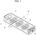
- FIG. 1 shows a schematic configuration of battery pack 10.
- Battery pack 10 is used as a power source for devices driven by electric motors, for example, electric vehicles, power-assisted bicycles, and electric motorcycles.
- the application of use of battery pack 10 is not limited to this, and battery pack 10 can be used as a power supply for various electric devices.
- Battery pack 10 includes outer covering case 20 made of metal such as aluminum, and one or a plurality of battery blocks 30 housed inside outer covering case 20.
- Battery block 30 includes a plurality of cells 31 arranged in line, and the plurality of cells 31 is electrically connected to each other.
- Battery block 30 includes a plurality of cells 31, for example, electrically connected in parallel or in series.
- Battery pack 10 includes a plurality of battery blocks 30 electrically connected in series or in parallel to output a voltage suitable for devices to be used.
- Cell 31 is, for example, a cylindrical battery. Note here that in this disclosure, although a cylindrical battery is described as an example of cell 31, a cell is not limited to the cylindrical battery, and may be a prismatic battery or the like.
- Cell 31 is a cylindrical battery including a bottomed cylindrical outer can and a sealing body that closes an opening of the outer can. Furthermore, an insulating gasket is provided between the outer can and the sealing body.
- the sealing body serves as a positive electrode terminal, and the outer can serves as a negative electrode terminal.
- the sealing body includes an exhaust valve for discharging gas when an abnormality occurs in cell 31 and the internal pressure rises. Note here that the exhaust valve may be provided at the bottom of the outer can.
- Battery block 30 includes a plurality of cells 31 housed in holder 50.
- Holder 50 of battery block 30 includes below-described heat insulating member 33 ( FIGs. 2A and 2B ) and two side surface members 35 ( FIGs. 2A and 2B ) with higher thermal conductivity than heat insulating member 33.
- Holder 50 fixes the arrangement of the plurality of cells 31 and maintains the form of battery block 30.
- battery pack 10 includes a terminal board (current collector board) for electrically connecting a plurality of battery blocks 30.
- the positive electrode terminal and the negative electrode terminal of battery block 30 are respectively connected to the terminal board.
- the terminal board and the holder may be integrated with each other.
- External terminal 40 electrically connected to battery block 30 is provided at the end part of outer covering case 20.
- External terminal 40 is used as a terminal for applying a DC voltage to a device into which battery pack 10 is to be installed. Furthermore, external terminal 40 is used also in charging cells 31 of battery pack 10. External terminal 40 may be provided at only one end part of battery pack 10, or may be provided in a plurality of places. Furthermore, a part including the outer surface of the battery block and formed of the heat insulating member or the side surface member may form the outer covering case.
- battery block 30 includes a plurality of cells 31, heat insulating member 33, two side surface members 35, and two position fixing members 37.
- the plurality of cells 31 is disposed adjacent to each other in a first direction.
- the first direction is a direction perpendicular to the axial direction of each cell 31.
- heat insulating member 33 is disposed between two cells 31, and two side surface members 35 are disposed in contact with the side surfaces of two cells 31 excluding a site provided with heat insulating member 33.
- Heat insulating member 33 and two side surface members 35 are integrally fixed. Thereby, the side surfaces of two cells 31 are covered with heat insulating member 33 and two side surface members 35.
- Two position fixing members 37 are respectively disposed at both end parts in the axial direction of two cells 31, and two cells 31 are sandwiched by two position fixing members 37 from both sides in the axial direction.
- FIG. 2A shows a state in which battery block 30 is integrally fixed.
- FIG. 2B shows a state before position fixing members 37 are attached to two cells 31, heat insulating member 33, and side surface members 35.
- heat insulating member 33 is a flat plate disposed between two cells 31 so as to be in contact with two cells 31 only at a position where the distance between the cells is the shortest and sandwiched between the cylindrical-shaped side surfaces of cells 31. At this time, heat insulating member 33 is located in all positions in a second direction perpendicular to the first direction and the axial direction of cell 31 excluding both ends in the axial direction of cell 31, between adjacent cells 31, and blocks the adjacent two cells 31.
- Side surface member 35 is disposed to cover almost the entire side surface of each cell 31 excluding a part where heat insulating member 33 is not disposed. Heat insulating member 33 and two side surface members 35 form holder 50 that is substantially rectangular parallelepiped and holds two cells inside.
- the length of holder 50 along the axial direction of cell 31 is formed to be smaller than the length of cell 31 in the axial direction. As shown in FIG. 2B , both end parts in the axial direction of cell 31 protrude from both end surfaces of holder 50 in the axial direction.
- Two position fixing members 37 are in substantially rectangular flat and are disposed at both ends in the axial direction of two cells 31.
- Each position fixing member 37 includes two openings 37a in the positions corresponding to the end surfaces in the axial direction of two cells 31.
- housing part 37b for housing the end part of cell 31 protruding from holder 50 is formed.
- Both end parts of cell 31 in the axial direction form electrode terminals.
- the electrode terminals of two cells 31 are electrically connected to current collector boards (not shown) through openings 37a of position fixing member 37.
- fitting claws 37c are formed at four corners of position fixing member 37.
- Fitting recesses 36 are formed in positions corresponding to fitting claws 37c in both ends of each side surface member 35 in the axial direction of cell 31.
- Two position fixing members 37 are coupled to two side surface members 35 from both end sides in the axial direction of cell 31 so that fitting claws 37c are fitted into fitting recesses 36. In this state, end parts of cells 31 are housed in housing parts 37b. Thus, battery block 30 is formed.
- the number of cells 31 of battery block 30 is not two, and may be three or more as shown in FIGs. 7 to 10 .
- FIGs. 2A and 2B show a configuration of battery block 30 including position fixing members 37 in both end parts in the axial direction of cell 31.
- the battery block may include heat insulating member 33 and side surface member 35 without including a position fixing member.
- FIG. 3A is a sectional view taken along the line A-A of FIG. 1 .
- FIG. 3B is a view in which outer covering case 20 is omitted from FIG. 3A .
- heat insulating member 33 with low heat conductive property is disposed between two cells 31.
- Heat insulating member 33 is made of, for example, materials including foamed resin, heat insulating resin, foamed concrete, gypsum board, glass wool, or silica aerogel. The physical properties of the material forming heat insulating member 33 is described later in detail.
- Heat insulating member 33 makes it difficult for the heat generated in one cell 31 to be transmitted to other adjacent cells 31.
- Side surface member 35 with higher thermal conductivity than that of heat insulating member 33 is disposed in contact with the side surface of cell 31 that is not in contact with heat insulating member 33.
- Side surface member 35 is made of, for example, a high heat conductive material including a thermosetting resin and a heat conductive filler. The physical properties of the materials forming side surface member 35 are described later in detail. As mentioned above, the heat generated in cell 31 is not easily transferred to other cells 31 adjacent to each other by heat insulating member 33, and is easily transmitted to side surface member 35 with high thermal conductivity.
- thermosetting resin is preferable, but a thermoplastic resin may be used.
- thermoplastic resin examples include thermosetting resins such as unsaturated polyester, epoxy resin, melamine resin, phenol resin, thermoplastic polycarbonate, polyethylene, polypropylene, polyvinyl chloride, and polystyrene, and thermoplastic resin such as polycarbonate, polyethylene, polypropylene, polyvinyl chloride, and polystyrene.
- the resin forming side surface member 35 may include a heat conductive filler formed of metal oxide (for example, aluminum oxide, zinc oxide), metal nitride (for example, aluminum nitride, boron nitride), and metal oxynitride (for example, aluminum oxynitride), or an endothermic filler formed of aluminum hydroxide, magnesium hydroxide, and sodium bicarbonate, as necessary.
- metal oxide for example, aluminum oxide, zinc oxide
- metal nitride for example, aluminum nitride, boron nitride
- metal oxynitride for example, aluminum oxynitride
- an endothermic filler formed of aluminum hydroxide, magnesium hydroxide, and sodium bicarbonate as necessary.
- Battery block 30 is housed in outer covering case 20 so that at least a part of side surface member 35 is in contact with the inner surface of outer covering case 20.
- the heat generated in cell 31 is easily transmitted to and absorbed by side surface member 35, and the heat absorbed by side surface member 35 is easily transmitted to outer covering case 20.
- the heat transmitted to outer covering case 20 is radiated to the outside.
- FIG. 4 is a diagram showing an applicable range of the thermal conductivity and a product of a specific heat and a density of each material of heat insulating member 33 and side surface member 35 in accordance with the exemplary embodiment.
- the horizontal axis represents thermal conductivity
- the vertical axis represents the product of a specific heat and a density.
- the product of the specific heat and the density corresponds to the heat capacity per unit volume.
- a range X shown by a thin dotted area of FIG. 4 indicates a range of the physical property values of the material used for heat insulating member 33 of this exemplary embodiment.
- a range Y shown by a thick dotted area of FIG. 4 indicates a range of physical property values of the material used for side surface member 35.
- different materials are used for heat insulating member 33 and side surface member 35.
- Black points A to T in FIG. 4 indicate virtual materials.
- ⁇ a and Ca satisfy 0.001 W / (m ⁇ K) ⁇ ⁇ a ⁇ 0.05 W / (m ⁇ K), and 0 ⁇ Ca ⁇ 2.5 J / (cm 3 ⁇ K), corresponding to the range X.
- ⁇ b and Cb satisfy 0.1 W / (m ⁇ K) ⁇ ⁇ b ⁇ 1.0 W / (m ⁇ K) and 1.75 ⁇ Cb ⁇ 3.25 J / (cm 3 ⁇ K), or satisfy 1.0 W / (m ⁇ K) ⁇ ⁇ b ⁇ 1000 W / (m ⁇ K) and 0.75 ⁇ Cb ⁇ 3.25 J / (cm 3 ⁇ K), corresponding to a range Y
- any one of the virtual materials A to C included in the range X can be used.
- any one of the virtual materials A to T included in the range Y can be used.
- heat insulating member 33 is provided between adjacent cells 31, and side surface member 35 whose thermal conductivity is higher than that of heat insulating member 33 is provided in contact with a side surface, excluding a site provided with heat insulating member 33, of the plurality of cells 31. Furthermore, in heat insulating member 33, the thermal conductivity is lower than that of side surface member 35, and the product of a specific heat and a density is relatively small. Furthermore, in side surface member 35, the thermal conductivity is higher than that of heat insulating member 33, and the product of a specific heat and a density is relatively large. Thus, heat is easily stored in side surface member 35 and is easily dissipated to the surroundings without excessively increasing the distance between the cells.
- heat insulating member 33 is located at all positions in the second direction at least in part in the axial direction of cells 31 between adjacent cells 31, adjacent cells 31 are completely blocked at least in part in the axial direction.
- the effect of suppressing the chain of thermal runaway of cells 31 can be further enhanced.
- a thermal fluid simulation was performed to evaluate the heat transfer from the thermal runaway cell to adjacent cell 31.
- a cell disposed adjacent to a thermal runaway cell may be referred to as an "adjacent cell.”
- battery block 30a with the sectional structure shown in FIG. 5 was used.
- the width of heat insulating member 33 in the first direction is larger.
- Heat insulating member 33 is disposed between two cells 31 and is in contact with a circular arc cross sectional area of the side surface of each cell 31 including the position other than the position where the distance between the cells is the shortest.
- Side surface member 35 is disposed to cover almost the entire side surface of each cell 31 excluding a part where heat insulating member 33 is not disposed.
- Other configurations of battery block 30a shown in FIG. 5 are similar to those of battery block 30 shown in FIGS. 3A and 3B .
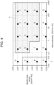
- FIG. 6 shows analysis results of evaluation of the suppression effect of the thermal runaway of cells 31 in a case where heat conductivities ⁇ a and ⁇ b, and products of a specific heat and a density Ca and Cb are varied in materials (heat insulating member material and side surface member material) forming each of heat insulating member 33 and side surface member 35.
- Vertical columns in FIG. 6 show virtual materials A to K to be used as heat insulating member materials and their respective heat conductivities ⁇ a, and (specific heat ⁇ density) Ca.
- Horizontal columns of FIG. 6 show virtual materials A to T to be used as side surface member materials and their respective heat conductivities ⁇ b and (specific heat ⁇ density) Cb.
- the circled characters indicate materials applicable to heat insulating member 33 or side surface member 35 in the exemplary embodiment.
- one of two adjacent cells 31 shown in FIG. 5 is assumed to be a thermally runaway cell and the other is assumed to be an adjacent cell, and the initial temperature of two cells 31 is a predetermined temperature that can be assumed based on the usage environment and the form of the battery pack.
- the cell size of each cell 31 is set to 18 mm in diameter and 65 mm in height (length in the axial direction).
- the shortest distance between adjacent cells 31 is set to 1 mm. Then, assuming that the thermally runaway cell generates heat with a predetermined value of heat, a simulation was performed to calculate the temperature rise of the adjacent cell.
- the table in FIG. 6 shows the results of the analysis mentioned above, and "X" in the table indicates that the maximum temperature of the adjacent battery in analysis exceeds a predetermined temperature Tmax as the heat resistance temperature of cell 31 in the combination of the corresponding heat insulating member material and side surface member material and that the effect of suppressing the thermal runaway is insufficient. Furthermore, “O” in the table of FIG. 6 indicates that the maximum temperature of the adjacent cell in the analysis is a predetermined temperature Tmax or less in the combination of the corresponding heat insulating member material and side surface member material and that the suppression effect of the thermal runaway is sufficient.
- battery block 30a includes two cells.
- the similar analysis results can be obtained by a configuration in which three or four cells 31 are disposed in the first direction or a configuration in which cells 31 are arranged in two rows in the second direction and each row includes two or three cells 31 in the first direction.
- the shortest distance between adjacent cells 31 is set to 1 mm, but the similar analysis results can be obtained when the shortest distance is, for example, in a range from 0.3 mm to 3 mm, other than 1 mm.
- the diameter of cell 31 is set to 18 mm, but the similar analysis result can be obtained when the diameter is, for example, in a range from 16 mm to 50 mm, other than 18 mm.
- the similar analysis results are obtained as long as the maximum length of heat insulating member 33 in the first direction is in a range from 0.3 mm to 10 mm. Furthermore, in the above analysis, similar analysis results can be obtained if the volume energy density of cell 31 exceeds 550 Wh/L.
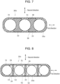
- FIG. 7 is a view showing another example of the exemplary embodiment corresponding to FIG. 3B .
- battery block 30b includes three cells 31 disposed adjacent to each other in the first direction, two heat insulating members 33 provided between cells 31, and side surface member 35a that is in contact with the side surface of cell 31 so as to surround the periphery of the side surfaces of three cells 31.
- the shape of each heat insulating member 33 is similar to that in the case of battery block 30a of FIG. 5 .
- Side surface member 35a is formed in a flat annular shape that is oblong in the first direction.
- Two heat insulating members 33 are coupled to be fitted into fitting grooves 38 formed on the inner circumference of side surface member 35a.
- side surface member 35a is formed in an annular shape with heat insulating member 33 disposed inside.
- Other configurations and actions in this example are similar to those in FIGs. 1 to 4 .
- FIG. 8 is a view showing another example of the exemplary embodiment corresponding to FIG. 3B .
- battery block 30c includes four cells 31 disposed adjacent to each other in the first direction, three heat insulating members 33 provided between cells 31, and side surface member 35b that is in contact with the side surface of cell 31 so as to surround the periphery of the side surfaces of four cells 31.
- the shape of each heat insulating member 33 is similar to the case of battery block 30a of FIG. 5 . Both end parts in the second direction of each heat insulating member 33 are coupled to be fitted into fitting grooves 39 formed on the inner circumference of side surface member 35b.
- FIG. 9 is a perspective view showing battery block 30d in another example in the exemplary embodiment.
- FIG. 10 is a sectional view taken along line B-B of FIG. 9 .
- battery block 30d includes four cells 31 held at the inside of side surface member 35c that is in a substantially square cylindrical shape and that includes lid parts 53 at the both ends in the axial direction.
- Four cells 31 are arranged in two rows in the second direction and each row includes two cells 31 arranged in the first direction.
- Openings 54 for exposing the electrode terminals of cells 31 are formed in lid parts 53 of side surface member 35c.
- a side surface of cell 31 is fitted into and held by each fitting recess 55 with a circular arc cross sectional shape formed in four corners on the inner peripheral surface of side surface member 35c.
- Heat insulating member 33a with a shape in which two plate parts are orthogonal to each other seen in a cross section is held on the inner peripheral surface of side surface member 35c. Heat insulating member 33a extends between adjacent cells 31 and blocks a place between the cells.
- Air layer 56 is formed between the adjacent cells in the first direction and the second direction.
- heat insulating member 33a and side surface of cell 31 are distant from each other, but the side surface of cell 31 may be brought into contact with heat insulating member 33a.
- Other configurations and actions in this example are similar to the configurations in FIGs. 1 to 4 , or FIG. 7, or FIG. 8 .
Landscapes
- Chemical & Material Sciences (AREA)
- Chemical Kinetics & Catalysis (AREA)
- Electrochemistry (AREA)
- General Chemical & Material Sciences (AREA)
- Engineering & Computer Science (AREA)
- Manufacturing & Machinery (AREA)
- Physics & Mathematics (AREA)
- Algebra (AREA)
- General Physics & Mathematics (AREA)
- Mathematical Analysis (AREA)
- Mathematical Optimization (AREA)
- Pure & Applied Mathematics (AREA)
- Battery Mounting, Suspending (AREA)
- Secondary Cells (AREA)
Abstract
Description
- The present disclosure relates to a battery pack.
- In general, a cylindrical cell (battery) such as a cylindrical lithium-ion battery is used in a form of a battery pack in which a plurality of the cylindrical cells is electrically connect and housed in a case. At this time, if one of the cells thermally runs away due to some abnormality and generates heat abnormally, the heat generated by the cell that has thermally run away (thermally runaway cell) propagates to surrounding cells, causing a chain of thermal runaways in the surrounding cells, a thermal effect may occur on the outside of the battery pack. In order to use a battery pack safely, it is important to prevent such a chain of thermal runaways of cells.
-
Patent literature 1 discloses a battery pack including a case housing a plurality of cylindrical batteries (cells). Between the batteries adjacent to each other in the short direction of the case, a spacer is provided. The spacer includes a core body made of a thermally deformable resin and two sheet bodies provided on both side surfaces of the core body. The sheet bodies are formed of materials with higher thermal resistance than the core body. - [PTL 1]
Japanese Unexamined Patent Application, Publication No. 2012-33464 - Examples of a method for preventing a chain of thermal runaways of cells include a method of reducing an amount of heat transferred from a thermally runaway cell to another cell by increasing a distance between adjacent cells in a battery pack. However, since this method increases a volume of the battery pack, there is room for improvement in terms of reduction in size of the battery pack. Furthermore, when a plurality of cells is adjacent to the thermally runaway cell, heat transfer from the thermally runaway cell is dispersed to the surrounding batteries, and the amount of heat transferred to one cell among the cells adjacent to the thermally runaway cell is reduced. On the other hand, when the number of cells adjacent to the thermal runaway cell is small, the amount of heat transferred to one cell among the cells adjacent to the thermal runaway cell increases.
- Furthermore, as a configuration described in
Patent literature 1, by only disposing thermally resistant members, there is room for improvement in terms of suppressing a chain of thermal runaways between adjacent cells. - An object of the present disclosure is to reduce in size of a battery pack and to enhance an effect of suppressing a chain of thermal runaway of cells.
- A battery pack of the present disclosure is a battery pack including a battery block including a plurality of cells and housed in an outer covering case, or a part including an outer surface of the battery block forming the outer covering case, and including a heat insulating member provided between the cells adjacent to each other among the plurality of cells; a side surface member disposed in contact with a side surface of the plurality of cells excluding a site including the heat insulating member, with higher thermal conductivity than the heat insulating member, wherein the heat insulating member and the side surface member are made of different materials; 0.001 W / (m×K) < λa < 0.05 W / (m×K) and 0 < Ca < 2.5 J / (cm3×K) are satisfied where λa denotes thermal conductivity of the heat insulating member, and Ca denotes a product value of a specific heat and a density; and 0.1 W / (m×K) < λb < 1.0 W / (m×K) and 1.75 < Cb < 3.25 J / (cm3×K) are satisfied or 1.0 W / (m×K) < λb < 1000 W / (m×K) and 0.75 < Cb < 3.25 J / (cm3×K) are satisfied where λb denotes thermal conductivity of the side surface member, and Cb denotes a product value of a specific heat and a density.
- According to the battery pack of the present disclosure, the heat insulating member is provided between the adjacent cells, and the side surface member whose thermal conductivity is higher than that of the heat insulating member is provided in contact with a side surface of the plurality of cells excluding a site provided with the heat insulating member. Furthermore, in the heat insulating member, the thermal conductivity is lower than the side surface member, and a product of a specific heat and a density is relatively small. Furthermore, in the side surface member, the thermal conductivity is higher than the heat insulating member, and the product of a specific heat and a density is relatively large. Thus, heat is easily stored in the side surface member and is easily dissipated to the surroundings without excessively increasing the distance between the cells. Thus, heat transfer from the abnormally heated thermally runaway cell to one of the cells adjacent to the thermally runaway cell can be reduced. Therefore, the effect of suppressing the chain of thermal runaways of the cells can be enhanced. Furthermore, since it is not necessary to make a space between the cells excessively large in order to suppress the chain of thermal runaways, a size of the battery pack can be reduced.
-
-
FIG. 1 is a schematic perspective view of a battery pack in accordance with one exemplary embodiment. -
FIG. 2A is a perspective view of a battery block including two adjacent cells in the battery pack ofFIG. 1 . -
FIG. 2B is a partially exploded perspective view showing a part of the battery block ofFIG. 2A . -
FIG. 3A is a cross-sectional view taken along line A-A ofFIG. 1 . -
FIG. 3B is a view ofFIG. 3A from which an outer covering case is omitted. -
FIG. 4 is a diagram showing an applicable range of a thermal conductivity and a product of a specific heat and a density of each material of the heat insulating member and the side surface member in accordance with the exemplary embodiment. -
FIG. 5 is a diagram corresponding toFIG. 3B of the battery block used for analyzing demonstrating the effect of the exemplary embodiment. -
FIG. 6 is a diagram showing analysis results for evaluating the effect of suppression of thermal runaway of the cells when the heat conductivities λa and λb and the products Ca and Cb of a specific heat and a density are changed in materials (a heat insulating member material and a side surface member material) each forming each of the heat insulating member and the side surface member. -
FIG. 7 is a view showing another example of the exemplary embodiment, corresponding toFIG. 3B . -
FIG. 8 is a view showing another example of the exemplary embodiment, corresponding toFIG. 3B . -
FIG. 9 is a perspective view showing a battery block in another example in the exemplary embodiment. -
FIG. 10 is a sectional view taken along line B-B ofFIG. 9 . - The exemplary embodiment of the present disclosure is described with reference to drawings. The shapes, materials, directions, and numbers described below are examples, and can be appropriately modified in accordance with specifications of battery packs. Furthermore, component elements of the exemplary embodiments, modifications, and the like, mentioned below are expected to be selectively coupled from the beginning.
-
FIG. 1 shows a schematic configuration ofbattery pack 10.Battery pack 10 is used as a power source for devices driven by electric motors, for example, electric vehicles, power-assisted bicycles, and electric motorcycles. The application of use ofbattery pack 10 is not limited to this, andbattery pack 10 can be used as a power supply for various electric devices. -
Battery pack 10 includesouter covering case 20 made of metal such as aluminum, and one or a plurality ofbattery blocks 30 housed insideouter covering case 20. -
Battery block 30 includes a plurality ofcells 31 arranged in line, and the plurality ofcells 31 is electrically connected to each other.Battery block 30 includes a plurality ofcells 31, for example, electrically connected in parallel or in series.Battery pack 10 includes a plurality ofbattery blocks 30 electrically connected in series or in parallel to output a voltage suitable for devices to be used. -
Cell 31 is, for example, a cylindrical battery. Note here that in this disclosure, although a cylindrical battery is described as an example ofcell 31, a cell is not limited to the cylindrical battery, and may be a prismatic battery or the like. -
Cell 31 is a cylindrical battery including a bottomed cylindrical outer can and a sealing body that closes an opening of the outer can. Furthermore, an insulating gasket is provided between the outer can and the sealing body. In a cylindrical battery, in general, the sealing body serves as a positive electrode terminal, and the outer can serves as a negative electrode terminal. The sealing body includes an exhaust valve for discharging gas when an abnormality occurs incell 31 and the internal pressure rises. Note here that the exhaust valve may be provided at the bottom of the outer can. -
Battery block 30 includes a plurality ofcells 31 housed inholder 50.Holder 50 ofbattery block 30 includes below-described heat insulating member 33 (FIGs. 2A and 2B ) and two side surface members 35 (FIGs. 2A and 2B ) with higher thermal conductivity thanheat insulating member 33.Holder 50 fixes the arrangement of the plurality ofcells 31 and maintains the form ofbattery block 30. Furthermore,battery pack 10 includes a terminal board (current collector board) for electrically connecting a plurality of battery blocks 30. The positive electrode terminal and the negative electrode terminal ofbattery block 30 are respectively connected to the terminal board. The terminal board and the holder may be integrated with each other. -
External terminal 40 electrically connected tobattery block 30 is provided at the end part ofouter covering case 20.External terminal 40 is used as a terminal for applying a DC voltage to a device into whichbattery pack 10 is to be installed. Furthermore,external terminal 40 is used also in chargingcells 31 ofbattery pack 10.External terminal 40 may be provided at only one end part ofbattery pack 10, or may be provided in a plurality of places. Furthermore, a part including the outer surface of the battery block and formed of the heat insulating member or the side surface member may form the outer covering case. - A structure of
battery block 30 is described with reference toFIGs. 2A and 2B . As shown inFIGs. 2A and 2B ,battery block 30 includes a plurality ofcells 31,heat insulating member 33, twoside surface members 35, and twoposition fixing members 37. Inbattery block 30, the plurality ofcells 31 is disposed adjacent to each other in a first direction. The first direction is a direction perpendicular to the axial direction of eachcell 31. - In
battery block 30,heat insulating member 33 is disposed between twocells 31, and twoside surface members 35 are disposed in contact with the side surfaces of twocells 31 excluding a site provided withheat insulating member 33. Heat insulatingmember 33 and twoside surface members 35 are integrally fixed. Thereby, the side surfaces of twocells 31 are covered withheat insulating member 33 and twoside surface members 35. Twoposition fixing members 37 are respectively disposed at both end parts in the axial direction of twocells 31, and twocells 31 are sandwiched by twoposition fixing members 37 from both sides in the axial direction.FIG. 2A shows a state in whichbattery block 30 is integrally fixed.FIG. 2B shows a state beforeposition fixing members 37 are attached to twocells 31,heat insulating member 33, andside surface members 35. - As shown in the below described
FIGs. 3A and 3B ,heat insulating member 33 is a flat plate disposed between twocells 31 so as to be in contact with twocells 31 only at a position where the distance between the cells is the shortest and sandwiched between the cylindrical-shaped side surfaces ofcells 31. At this time,heat insulating member 33 is located in all positions in a second direction perpendicular to the first direction and the axial direction ofcell 31 excluding both ends in the axial direction ofcell 31, betweenadjacent cells 31, and blocks the adjacent twocells 31.Side surface member 35 is disposed to cover almost the entire side surface of eachcell 31 excluding a part whereheat insulating member 33 is not disposed. Heat insulatingmember 33 and twoside surface members 35form holder 50 that is substantially rectangular parallelepiped and holds two cells inside. - The length of
holder 50 along the axial direction ofcell 31 is formed to be smaller than the length ofcell 31 in the axial direction. As shown inFIG. 2B , both end parts in the axial direction ofcell 31 protrude from both end surfaces ofholder 50 in the axial direction. - Two
position fixing members 37 are in substantially rectangular flat and are disposed at both ends in the axial direction of twocells 31. Eachposition fixing member 37 includes twoopenings 37a in the positions corresponding to the end surfaces in the axial direction of twocells 31. At a position with whichcell 31 is brought into contact in a peripheral edge part of opening 37a of eachposition fixing member 37,housing part 37b for housing the end part ofcell 31 protruding fromholder 50 is formed. Both end parts ofcell 31 in the axial direction form electrode terminals. The electrode terminals of twocells 31 are electrically connected to current collector boards (not shown) throughopenings 37a ofposition fixing member 37. - At four corners of
position fixing member 37,fitting claws 37c are formed. Fitting recesses 36 are formed in positions corresponding tofitting claws 37c in both ends of eachside surface member 35 in the axial direction ofcell 31. Twoposition fixing members 37 are coupled to twoside surface members 35 from both end sides in the axial direction ofcell 31 so thatfitting claws 37c are fitted into fitting recesses 36. In this state, end parts ofcells 31 are housed inhousing parts 37b. Thus,battery block 30 is formed. - The number of
cells 31 ofbattery block 30 is not two, and may be three or more as shown inFIGs. 7 to 10 .FIGs. 2A and 2B show a configuration ofbattery block 30 includingposition fixing members 37 in both end parts in the axial direction ofcell 31. However, the battery block may includeheat insulating member 33 andside surface member 35 without including a position fixing member. - A heat transmitting structure of
cells 31 in thebattery pack 10 of the present disclosure is described with reference toFIGs. 3A and 3B. FIG. 3A is a sectional view taken along the line A-A ofFIG. 1 .FIG. 3B is a view in whichouter covering case 20 is omitted fromFIG. 3A . - In
battery pack 10 of the present disclosure,heat insulating member 33 with low heat conductive property is disposed between twocells 31. Heat insulatingmember 33 is made of, for example, materials including foamed resin, heat insulating resin, foamed concrete, gypsum board, glass wool, or silica aerogel. The physical properties of the material formingheat insulating member 33 is described later in detail. Heat insulatingmember 33 makes it difficult for the heat generated in onecell 31 to be transmitted to otheradjacent cells 31.Side surface member 35 with higher thermal conductivity than that ofheat insulating member 33 is disposed in contact with the side surface ofcell 31 that is not in contact withheat insulating member 33. -
Side surface member 35 is made of, for example, a high heat conductive material including a thermosetting resin and a heat conductive filler. The physical properties of the materials formingside surface member 35 are described later in detail. As mentioned above, the heat generated incell 31 is not easily transferred toother cells 31 adjacent to each other byheat insulating member 33, and is easily transmitted toside surface member 35 with high thermal conductivity. - As the resin forming
side surface member 35, a thermosetting resin is preferable, but a thermoplastic resin may be used. Examples of the resin formingside surface member 35 include thermosetting resins such as unsaturated polyester, epoxy resin, melamine resin, phenol resin, thermoplastic polycarbonate, polyethylene, polypropylene, polyvinyl chloride, and polystyrene, and thermoplastic resin such as polycarbonate, polyethylene, polypropylene, polyvinyl chloride, and polystyrene. - The resin forming
side surface member 35 may include a heat conductive filler formed of metal oxide (for example, aluminum oxide, zinc oxide), metal nitride (for example, aluminum nitride, boron nitride), and metal oxynitride (for example, aluminum oxynitride), or an endothermic filler formed of aluminum hydroxide, magnesium hydroxide, and sodium bicarbonate, as necessary. -
Battery block 30 is housed inouter covering case 20 so that at least a part ofside surface member 35 is in contact with the inner surface ofouter covering case 20. The heat generated incell 31 is easily transmitted to and absorbed byside surface member 35, and the heat absorbed byside surface member 35 is easily transmitted toouter covering case 20. The heat transmitted toouter covering case 20 is radiated to the outside. - Next, physical properties of
heat insulating member 33 andside surface member 35 are described with reference toFIG. 4. FIG. 4 is a diagram showing an applicable range of the thermal conductivity and a product of a specific heat and a density of each material ofheat insulating member 33 andside surface member 35 in accordance with the exemplary embodiment. InFIG. 4 , the horizontal axis represents thermal conductivity, and the vertical axis represents the product of a specific heat and a density. The product of the specific heat and the density corresponds to the heat capacity per unit volume. - A range X shown by a thin dotted area of
FIG. 4 indicates a range of the physical property values of the material used forheat insulating member 33 of this exemplary embodiment. A range Y shown by a thick dotted area ofFIG. 4 indicates a range of physical property values of the material used forside surface member 35. As shown inFIG. 4 , different materials are used forheat insulating member 33 andside surface member 35. Black points A to T inFIG. 4 indicate virtual materials. - In this exemplary embodiment, when the thermal conductivity of
heat insulating member 33 is denoted by λa, and the product value of a specific heat and a density is denoted by Ca, λa and Ca satisfy 0.001 W / (m×K) < λa < 0.05 W / (m×K), and 0 < Ca < 2.5 J / (cm3×K), corresponding to the range X. Furthermore, in the exemplary embodiment, when thermal conductivity ofside surface member 35 is denoted by λb, and a product value of a specific heat and a density is denoted by Cb, λb and Cb satisfy 0.1 W / (m×K) < λb < 1.0 W / (m×K) and 1.75 < Cb < 3.25 J / (cm3×K), or satisfy 1.0 W / (m×K) < λb < 1000 W / (m×K) and 0.75 < Cb < 3.25 J / (cm3×K), corresponding to a range Y - For example, for materials of
heat insulating member 33 of the exemplary embodiment, any one of the virtual materials A to C included in the range X can be used. Furthermore, for materials ofside surface member 35 of the exemplary embodiment, any one of the virtual materials A to T included in the range Y can be used. - According to
battery pack 10 mentioned above,heat insulating member 33 is provided betweenadjacent cells 31, andside surface member 35 whose thermal conductivity is higher than that ofheat insulating member 33 is provided in contact with a side surface, excluding a site provided withheat insulating member 33, of the plurality ofcells 31. Furthermore, inheat insulating member 33, the thermal conductivity is lower than that ofside surface member 35, and the product of a specific heat and a density is relatively small. Furthermore, inside surface member 35, the thermal conductivity is higher than that ofheat insulating member 33, and the product of a specific heat and a density is relatively large. Thus, heat is easily stored inside surface member 35 and is easily dissipated to the surroundings without excessively increasing the distance between the cells. Thus, heat transfer from an abnormally heated thermally runaway cell to one ofcells 31 adjacent to the thermally runaway cell can be reduced. As a result, the effect of suppressing the chain of thermal runaways ofcells 31 can be enhanced. Furthermore, since it is not necessary to make a space between the cells excessively large in order to suppress the chain of thermal runaways, a size ofbattery pack 10 can be reduced. - Furthermore, since
heat insulating member 33 is located at all positions in the second direction at least in part in the axial direction ofcells 31 betweenadjacent cells 31,adjacent cells 31 are completely blocked at least in part in the axial direction. Thus, the effect of suppressing the chain of thermal runaway ofcells 31 can be further enhanced. - Next, results of analysis performed to check the effect of the exemplary embodiment are described. In the analysis, a thermal fluid simulation was performed to evaluate the heat transfer from the thermal runaway cell to
adjacent cell 31. Hereinafter, a cell disposed adjacent to a thermal runaway cell may be referred to as an "adjacent cell." - In the analysis,
battery block 30a with the sectional structure shown inFIG. 5 was used. In the structure ofFIG. 5 , as compared with the structure shown inFIGs. 3A and 3B , the width ofheat insulating member 33 in the first direction is larger. Heat insulatingmember 33 is disposed between twocells 31 and is in contact with a circular arc cross sectional area of the side surface of eachcell 31 including the position other than the position where the distance between the cells is the shortest.Side surface member 35 is disposed to cover almost the entire side surface of eachcell 31 excluding a part whereheat insulating member 33 is not disposed. Other configurations ofbattery block 30a shown inFIG. 5 are similar to those ofbattery block 30 shown inFIGS. 3A and 3B . -
FIG. 6 shows analysis results of evaluation of the suppression effect of the thermal runaway ofcells 31 in a case where heat conductivities λa and λb, and products of a specific heat and a density Ca and Cb are varied in materials (heat insulating member material and side surface member material) forming each ofheat insulating member 33 andside surface member 35. Vertical columns inFIG. 6 show virtual materials A to K to be used as heat insulating member materials and their respective heat conductivities λa, and (specific heat × density) Ca. Horizontal columns ofFIG. 6 show virtual materials A to T to be used as side surface member materials and their respective heat conductivities λb and (specific heat × density) Cb. In the columns of virtual materials A to T inFIG. 6 , the circled characters indicate materials applicable to heat insulatingmember 33 orside surface member 35 in the exemplary embodiment. - Furthermore, in the analysis, one of two
adjacent cells 31 shown inFIG. 5 is assumed to be a thermally runaway cell and the other is assumed to be an adjacent cell, and the initial temperature of twocells 31 is a predetermined temperature that can be assumed based on the usage environment and the form of the battery pack. Furthermore, the cell size of eachcell 31 is set to 18 mm in diameter and 65 mm in height (length in the axial direction). Furthermore, the shortest distance betweenadjacent cells 31 is set to 1 mm. Then, assuming that the thermally runaway cell generates heat with a predetermined value of heat, a simulation was performed to calculate the temperature rise of the adjacent cell. - The table in
FIG. 6 shows the results of the analysis mentioned above, and "X" in the table indicates that the maximum temperature of the adjacent battery in analysis exceeds a predetermined temperature Tmax as the heat resistance temperature ofcell 31 in the combination of the corresponding heat insulating member material and side surface member material and that the effect of suppressing the thermal runaway is insufficient. Furthermore, "O" in the table ofFIG. 6 indicates that the maximum temperature of the adjacent cell in the analysis is a predetermined temperature Tmax or less in the combination of the corresponding heat insulating member material and side surface member material and that the suppression effect of the thermal runaway is sufficient. - As is apparent from comparison between O and X in
FIG. 6 , it was demonstrated that the effect of suppressing the chain of the thermal runaway was good when the virtual materials A to C included in the applicable range (the range X ofFIG. 4 ) of the exemplary embodiment are used as the heat insulating member material and when the virtual materials G, H, J, K, L, N, O, P, R, S, and T included in the applicable range (the range Y ofFIG. 4 ) of the exemplary embodiment are used as the side surface member material. - The above analysis was performed using
battery block 30a with the sectional structure shown inFIG. 5 , but the similar analysis results can be obtained usingbattery block 30 with the sectional structure shown inFIG. 3B . This demonstrated the effect of the exemplary embodiment. - Furthermore, in the above analysis,
battery block 30a includes two cells. On the other hand, as shown in the other example described later, the similar analysis results can be obtained by a configuration in which three or fourcells 31 are disposed in the first direction or a configuration in whichcells 31 are arranged in two rows in the second direction and each row includes two or threecells 31 in the first direction. - In the above analysis, the shortest distance between
adjacent cells 31 is set to 1 mm, but the similar analysis results can be obtained when the shortest distance is, for example, in a range from 0.3 mm to 3 mm, other than 1 mm. - Furthermore, in the above analysis, the diameter of
cell 31 is set to 18 mm, but the similar analysis result can be obtained when the diameter is, for example, in a range from 16 mm to 50 mm, other than 18 mm. - Furthermore, in the above analysis, the similar analysis results are obtained as long as the maximum length of
heat insulating member 33 in the first direction is in a range from 0.3 mm to 10 mm. Furthermore, in the above analysis, similar analysis results can be obtained if the volume energy density ofcell 31 exceeds 550 Wh/L. -
FIG. 7 is a view showing another example of the exemplary embodiment corresponding toFIG. 3B . In the configuration of this example,battery block 30b includes threecells 31 disposed adjacent to each other in the first direction, twoheat insulating members 33 provided betweencells 31, andside surface member 35a that is in contact with the side surface ofcell 31 so as to surround the periphery of the side surfaces of threecells 31. The shape of eachheat insulating member 33 is similar to that in the case ofbattery block 30a ofFIG. 5 .Side surface member 35a is formed in a flat annular shape that is oblong in the first direction. Twoheat insulating members 33 are coupled to be fitted intofitting grooves 38 formed on the inner circumference ofside surface member 35a. Thus,side surface member 35a is formed in an annular shape withheat insulating member 33 disposed inside. Other configurations and actions in this example are similar to those inFIGs. 1 to 4 . -
FIG. 8 is a view showing another example of the exemplary embodiment corresponding toFIG. 3B . In the configuration of this example,battery block 30c includes fourcells 31 disposed adjacent to each other in the first direction, threeheat insulating members 33 provided betweencells 31, andside surface member 35b that is in contact with the side surface ofcell 31 so as to surround the periphery of the side surfaces of fourcells 31. The shape of eachheat insulating member 33 is similar to the case ofbattery block 30a ofFIG. 5 . Both end parts in the second direction of eachheat insulating member 33 are coupled to be fitted intofitting grooves 39 formed on the inner circumference ofside surface member 35b. -
Side surface member 35b is not brought into contact withheat insulating member 33 in a place other thanfitting grooves 39. At the inside ofside surface member 35b, an air layer is formed between both side surfaces in the first direction ofheat insulating member 33 andside surface member 35b. Thus,air layer 52 is formed between the adjacent cells. InFIG. 8 ,heat insulating member 33 and the side surface ofcell 31 are apart from each other, but the side surface ofcell 31 may be in contact withheat insulating member 33. In this example, the other configuration and actions are similar to the configurations ofFIGs. 1 to 4 or configuration ofFIG. 7 . -
FIG. 9 is a perspective view showingbattery block 30d in another example in the exemplary embodiment.FIG. 10 is a sectional view taken along line B-B ofFIG. 9 . In the configuration of this example,battery block 30d includes fourcells 31 held at the inside ofside surface member 35c that is in a substantially square cylindrical shape and that includeslid parts 53 at the both ends in the axial direction. Fourcells 31 are arranged in two rows in the second direction and each row includes twocells 31 arranged in the first direction.Openings 54 for exposing the electrode terminals ofcells 31 are formed inlid parts 53 ofside surface member 35c. - Furthermore, as shown in
FIG. 10 , a side surface ofcell 31 is fitted into and held by eachfitting recess 55 with a circular arc cross sectional shape formed in four corners on the inner peripheral surface ofside surface member 35c. Heat insulatingmember 33a with a shape in which two plate parts are orthogonal to each other seen in a cross section is held on the inner peripheral surface ofside surface member 35c. Heat insulatingmember 33a extends betweenadjacent cells 31 and blocks a place between the cells.Air layer 56 is formed between the adjacent cells in the first direction and the second direction. InFIG. 10 ,heat insulating member 33a and side surface ofcell 31 are distant from each other, but the side surface ofcell 31 may be brought into contact withheat insulating member 33a. Other configurations and actions in this example are similar to the configurations inFIGs. 1 to 4 , orFIG. 7, or FIG. 8 . - Note here that the present disclosure is not limited to the above-described exemplary embodiments and modifications thereof, and it goes without saying that various modifications and improvements are possible within the scope of the matters described in claims of the present application.
- 10: battery pack, 20: outer covering case, 30, 30a to 30d: battery block, 31: cell (battery), 33,33a: heat insulating member, 35, 35a, 35b, 35c: side surface member, 36: fitting recess, 37: position fixing member, 37a: opening, 37b: housing part, 37c: fitting claw, 38, 39: fitting groove, 40: external terminal, 50: holder, 52: air layer, 53: lid part, 54: opening, 55: fitting recess, 56: air layer
Claims (6)
- A battery pack comprising
a battery block including a plurality of cells, and housed in an outer covering case, or a part including an outer surface of the battery block forming an outer covering case, and comprising:a heat insulating member provided between cells adjacent to each other among the plurality of cells;a side surface member disposed in contact with a side surface of the plurality of cells excluding a site including the heat insulating member, with a higher thermal conductivity than a thermal conductivity of the heat insulating member,wherein the heat insulating member and the side surface member includes different materials each other;0.001 W / (m×K) < λa < 0.05 W / (m×K) and 0 < Ca < 2.5 J / (cm3×K) are satisfied where λa denotes thermal conductivity of the heat insulating member, and Ca denotes a product value of a specific heat and a density; and0.1 W / (m×K) < λb < 1.0 W / (m×K) and 1.75 < Cb < 3.25 J / (cm3×K) are satisfied or 1.0 W / (m×K) < λb < 1000 W / (m×K) and 0.75 < Cb < 3.25 J / (cm3×K) are satisfied where λb denotes thermal conductivity of the side surface member, and Cb denotes a product value of a specific heat and a density. - The battery pack according to claim 1, whereinthe cells adjacent to each other are disposed adjacent to each other in a first direction, andthe heat insulating member is positioned between the cells adjacent to each other in all positions in a second direction perpendicular to the first direction in at least a part along the axis.
- The battery pack according to claim 2,
wherein the heat insulating member is disposed between the cells adjacent to each other, and sandwiched by the plurality of side surface members. - The battery pack according to claim 1 or 2,
wherein the side surface member is in an annular shape with the heat insulating member disposed inside. - The battery pack according to any one of claims 1 to 4,
wherein the battery pack includes an air layer between the cells adjacent to each other. - The battery pack according to any one of claims 1 to 5,
wherein a shortest distance between the cells adjacent to each other is 0.3 mm to 3.0 mm.
Applications Claiming Priority (2)
| Application Number | Priority Date | Filing Date | Title |
|---|---|---|---|
| JP2021210534 | 2021-12-24 | ||
| PCT/JP2022/046500 WO2023120435A1 (en) | 2021-12-24 | 2022-12-16 | Battery pack |
Publications (2)
| Publication Number | Publication Date |
|---|---|
| EP4456263A1 true EP4456263A1 (en) | 2024-10-30 |
| EP4456263A4 EP4456263A4 (en) | 2025-04-09 |
Family
ID=86902701
Family Applications (1)
| Application Number | Title | Priority Date | Filing Date |
|---|---|---|---|
| EP22911138.0A Pending EP4456263A4 (en) | 2021-12-24 | 2022-12-16 | BATTERY PACK |
Country Status (5)
| Country | Link |
|---|---|
| US (1) | US20250132422A1 (en) |
| EP (1) | EP4456263A4 (en) |
| JP (1) | JPWO2023120435A1 (en) |
| CN (1) | CN118285008A (en) |
| WO (1) | WO2023120435A1 (en) |
Family Cites Families (6)
| Publication number | Priority date | Publication date | Assignee | Title |
|---|---|---|---|---|
| JP2012033464A (en) | 2010-07-02 | 2012-02-16 | Sanyo Electric Co Ltd | Battery pack |
| JP2019053816A (en) * | 2016-01-28 | 2019-04-04 | 三洋電機株式会社 | Battery pack |
| CN109565005B (en) * | 2016-08-24 | 2022-03-29 | 松下知识产权经营株式会社 | Battery module |
| JP7285446B2 (en) * | 2019-04-25 | 2023-06-02 | パナソニックIpマネジメント株式会社 | Battery packs for power tools, power tools |
| CN114080718B (en) * | 2019-07-29 | 2023-08-25 | 松下新能源株式会社 | Battery pack |
| WO2021256093A1 (en) * | 2020-06-18 | 2021-12-23 | 阿波製紙株式会社 | Insulating sheet and power supply device comprising same |
-
2022
- 2022-12-16 EP EP22911138.0A patent/EP4456263A4/en active Pending
- 2022-12-16 CN CN202280077423.6A patent/CN118285008A/en active Pending
- 2022-12-16 WO PCT/JP2022/046500 patent/WO2023120435A1/en not_active Ceased
- 2022-12-16 JP JP2023569408A patent/JPWO2023120435A1/ja active Pending
- 2022-12-16 US US18/715,773 patent/US20250132422A1/en active Pending
Also Published As
| Publication number | Publication date |
|---|---|
| CN118285008A (en) | 2024-07-02 |
| EP4456263A4 (en) | 2025-04-09 |
| JPWO2023120435A1 (en) | 2023-06-29 |
| WO2023120435A1 (en) | 2023-06-29 |
| US20250132422A1 (en) | 2025-04-24 |
Similar Documents
| Publication | Publication Date | Title |
|---|---|---|
| US11563255B2 (en) | Power supply device, and separator for power supply device | |
| KR102082384B1 (en) | Battery Pack Comprising Metallic Pack Case and Thermal Conduction Member | |
| EP3671946B1 (en) | Battery module having improved cooling structure | |
| KR102311508B1 (en) | Battery module including a housing floor with integrated cooling | |
| KR102014462B1 (en) | Cartridge for secondary battery and battery module including the same | |
| US10763469B2 (en) | Energy storage apparatus | |
| KR102762539B1 (en) | Busbar Frame Assembly and Battery module including the same | |
| JP5067171B2 (en) | Electrochemical storage element module | |
| KR102555088B1 (en) | Preparing method for secondary battery | |
| JP2020537311A (en) | Battery pack with degassing flow path | |
| US11888181B2 (en) | Battery pack including insulating tube | |
| CN114730940A (en) | Battery pack having structure for preventing heat diffusion between battery modules | |
| WO2014027783A1 (en) | Battery module comprising venting guidance portion | |
| WO2016067517A1 (en) | Battery pack and heat dissipating holder | |
| JP2022542077A (en) | Battery modules, battery racks containing the same, and power storage devices | |
| KR20230145281A (en) | Battery Module Having Heat Shielding Function | |
| KR20190054300A (en) | Battery | |
| KR20220033931A (en) | A battery pack with thermal propagation prevention structure between battery modules | |
| WO2014017779A1 (en) | Rectangular battery cell having pouch-shaped battery cell built therein | |
| KR20140004835A (en) | Battery pack | |
| JP2010186715A (en) | Heat radiation structure of battery pack, and battery pack | |
| KR20230012931A (en) | Battery module, battery pack comprising the battery module and vehicle comprising the battery pack | |
| US20250132422A1 (en) | Battery pack | |
| KR20200073721A (en) | Battery Pack | |
| EP4564557A1 (en) | Battery, battery module, and vehicle having battery module |
Legal Events
| Date | Code | Title | Description |
|---|---|---|---|
| STAA | Information on the status of an ep patent application or granted ep patent |
Free format text: STATUS: THE INTERNATIONAL PUBLICATION HAS BEEN MADE |
|
| PUAI | Public reference made under article 153(3) epc to a published international application that has entered the european phase |
Free format text: ORIGINAL CODE: 0009012 |
|
| STAA | Information on the status of an ep patent application or granted ep patent |
Free format text: STATUS: REQUEST FOR EXAMINATION WAS MADE |
|
| 17P | Request for examination filed |
Effective date: 20240528 |
|
| AK | Designated contracting states |
Kind code of ref document: A1 Designated state(s): AL AT BE BG CH CY CZ DE DK EE ES FI FR GB GR HR HU IE IS IT LI LT LU LV MC ME MK MT NL NO PL PT RO RS SE SI SK SM TR |
|
| REG | Reference to a national code |
Ref country code: DE Ref legal event code: R079 Free format text: PREVIOUS MAIN CLASS: H01M0010658000 Ipc: H01M0010613000 |
|
| DAV | Request for validation of the european patent (deleted) | ||
| DAX | Request for extension of the european patent (deleted) | ||
| A4 | Supplementary search report drawn up and despatched |
Effective date: 20250311 |
|
| RIC1 | Information provided on ipc code assigned before grant |
Ipc: H01M 50/293 20210101ALI20250305BHEP Ipc: H01M 50/291 20210101ALI20250305BHEP Ipc: H01M 50/244 20210101ALI20250305BHEP Ipc: H01M 50/204 20210101ALI20250305BHEP Ipc: H01M 50/213 20210101ALI20250305BHEP Ipc: H01M 10/653 20140101ALI20250305BHEP Ipc: H01M 10/647 20140101ALI20250305BHEP Ipc: H01M 10/643 20140101ALI20250305BHEP Ipc: H01M 10/651 20140101ALI20250305BHEP Ipc: H01M 10/658 20140101ALI20250305BHEP Ipc: H01M 10/613 20140101AFI20250305BHEP |