EP4456097A1 - A transformer arrangement - Google Patents
A transformer arrangement Download PDFInfo
- Publication number
- EP4456097A1 EP4456097A1 EP23170439.6A EP23170439A EP4456097A1 EP 4456097 A1 EP4456097 A1 EP 4456097A1 EP 23170439 A EP23170439 A EP 23170439A EP 4456097 A1 EP4456097 A1 EP 4456097A1
- Authority
- EP
- European Patent Office
- Prior art keywords
- transformer
- winding
- auxiliary
- auxiliary winding
- windings
- Prior art date
- Legal status (The legal status is an assumption and is not a legal conclusion. Google has not performed a legal analysis and makes no representation as to the accuracy of the status listed.)
- Pending
Links
Images


Classifications
-
- H—ELECTRICITY
- H01—ELECTRIC ELEMENTS
- H01F—MAGNETS; INDUCTANCES; TRANSFORMERS; SELECTION OF MATERIALS FOR THEIR MAGNETIC PROPERTIES
- H01F27/00—Details of transformers or inductances, in general
- H01F27/28—Coils; Windings; Conductive connections
- H01F27/30—Fastening or clamping coils, windings, or parts thereof together; Fastening or mounting coils or windings on core, casing, or other support
- H01F27/306—Fastening or mounting coils or windings on core, casing or other support
-
- H—ELECTRICITY
- H01—ELECTRIC ELEMENTS
- H01F—MAGNETS; INDUCTANCES; TRANSFORMERS; SELECTION OF MATERIALS FOR THEIR MAGNETIC PROPERTIES
- H01F27/00—Details of transformers or inductances, in general
- H01F27/24—Magnetic cores
-
- H—ELECTRICITY
- H01—ELECTRIC ELEMENTS
- H01F—MAGNETS; INDUCTANCES; TRANSFORMERS; SELECTION OF MATERIALS FOR THEIR MAGNETIC PROPERTIES
- H01F27/00—Details of transformers or inductances, in general
- H01F27/34—Special means for preventing or reducing unwanted electric or magnetic effects, e.g. no-load losses, reactive currents, harmonics, oscillations, leakage fields
- H01F27/38—Auxiliary core members; Auxiliary coils or windings
-
- H—ELECTRICITY
- H01—ELECTRIC ELEMENTS
- H01F—MAGNETS; INDUCTANCES; TRANSFORMERS; SELECTION OF MATERIALS FOR THEIR MAGNETIC PROPERTIES
- H01F27/00—Details of transformers or inductances, in general
- H01F27/40—Structural association with built-in electric component, e.g. fuse
-
- H—ELECTRICITY
- H01—ELECTRIC ELEMENTS
- H01F—MAGNETS; INDUCTANCES; TRANSFORMERS; SELECTION OF MATERIALS FOR THEIR MAGNETIC PROPERTIES
- H01F30/00—Fixed transformers not covered by group H01F19/00
- H01F30/04—Fixed transformers not covered by group H01F19/00 having two or more secondary windings, each supplying a separate load, e.g. for radio set power supplies
-
- H—ELECTRICITY
- H01—ELECTRIC ELEMENTS
- H01F—MAGNETS; INDUCTANCES; TRANSFORMERS; SELECTION OF MATERIALS FOR THEIR MAGNETIC PROPERTIES
- H01F27/00—Details of transformers or inductances, in general
- H01F27/08—Cooling; Ventilating
- H01F27/10—Liquid cooling
- H01F27/12—Oil cooling
-
- H—ELECTRICITY
- H01—ELECTRIC ELEMENTS
- H01F—MAGNETS; INDUCTANCES; TRANSFORMERS; SELECTION OF MATERIALS FOR THEIR MAGNETIC PROPERTIES
- H01F30/00—Fixed transformers not covered by group H01F19/00
- H01F30/06—Fixed transformers not covered by group H01F19/00 characterised by the structure
- H01F30/12—Two-phase, three-phase or polyphase transformers
Definitions
- the present disclosure relates to a transformer arrangement having an auxiliary winding.
- the disclosure relates to limiting short-circuit currents in such auxiliary windings.
- an auxiliary winding such as a tertiary winding may be coaxially arranged with the main windings, i.e. with the primary and secondary windings. See Fig. 1 .
- the auxiliary winding may for instance be used to supply power to devices at a transformer station, such as lighting, heating and cooling at the transformer station.
- Auxiliary windings are particularly useful in remote places which lack access to regular grid power. Tertiary winding arrangements add to the radial size of the transformer windings and to the transformer as a whole. It also adds to the cost of the transformer.
- Another type of auxiliary winding is a yoke winding, i.e. an auxiliary winding arranged around a yoke of the transformer. As an auxiliary winding, such a yoke winding is smaller, lighter and less expensive when compared to a coaxial tertiary winding.
- Yoke windings have traditionally had a voltage level below 1kV which may be considered a low voltage application. Lately, yoke windings have been used at around 7 kV, which may be considered a medium voltage application.
- a cabinet external to the transformer is required.
- the cabinet comprises a fuse protecting the auxiliary winding from high short-circuit currents since the auxiliary winding is not inherently short-circuit proof.
- external cabinets require extra work and maintenance on site.
- an object of the disclosure is to provide an improved transformer arrangement having an auxiliary winding which is protected from damaging short-circuit currents.
- the auxiliary winding is a yoke winding and the transformer arrangement does not require a cabinet.
- the object is at least partly achieved by a transformer arrangement according to claim 1.
- a transformer arrangement having at least one transformer comprising a transformer core, which comprises a bottom yoke and a top yoke interconnected by at least one limb extending along a first axis.
- the transformer arrangement further comprises at least a first winding and a second winding coaxially arranged around the at least one limb.
- an auxiliary winding is arranged around the at least one limb and is positioned axially between the first and second windings, and the bottom yoke or the top yoke.
- the auxiliary winding is magnetically coupled to the at least first winding and/or the second winding.
- the transformer arrangement further comprises a series reactor connected to the auxiliary winding.
- the first axis may be substantially vertically aligned.
- the auxiliary winding is positioned around the limb between an axial end of the first and second windings and the top or bottom yoke, i.e. axially between the first and second windings and the top or bottom yoke.
- the auxiliary winding is positioned such that it is magnetically coupled to the first and second windings and configured deliver a part of the power of the main windings to at least one auxiliary device.
- the transformer When the transformer is a multi-phase transformer, such as a three-phase transformer, the transformer comprises multiple limbs, e.g. one limb per phase. Each limb may be provided with an auxiliary winding, resulting in a three-phase power supply for auxiliary equipment and devices. Obviously, each auxiliary winding may be connected to a respective series reactor.
- the series reactor comprises at least one impedance element connected in series with the auxiliary winding.
- the reactor is passive during normal operation of the auxiliary winding. At the occurrence of a short-circuit event in the auxiliary winding, a suddenly increased current through the reactor generates a magnetic field which induces an opposed current in the reactor, which in turn reduces and limits the short-circuit current.
- the auxiliary winding is configured to deliver auxiliary power from the transformer via the series reactor to at least one auxiliary device.
- the auxiliary winding is magnetically coupled to the first and second windings of the transformer. Power may thereby be generated in the auxiliary winding and delivered to auxiliary devices and equipment.
- auxiliary devices and equipment may be power consumers used locally at a transformer station, e.g. devices for lighting, heating and/or cooling, such as when the transformer station is in a remote location and is not connected to a grid which could supply the devices.
- the auxiliary winding is dimensioned and configured to deliver power at a voltage level suitable for the auxiliary devices.
- the transformer arrangement further comprises at least one support element positioned between an axial end of the first and second windings and the bottom yoke and/or the top yoke.
- the auxiliary winding may be supported by the support element.
- the support element is an element configured to mechanically support the windings.
- the support element may be formed of an electrically insulating material and may be in physical contact with the windings.
- the support element may for example be a so-called common spacer ring.
- the support element may be supported on the bottom yoke and the auxiliary winding may be supported by the support element on an upper side of the support element.
- the auxiliary winding may be supported by the support element on an upper side of the support element.
- the support element is a ring comprising an annular groove, which annular groove circumscribes the limb.
- the auxiliary winding may be arranged in the annular groove.
- the auxiliary winding is assembled with the transformer without increasing its size, since the auxiliary winding is housed in an existing component, i.e. in the groove of the support element.
- a rated power of at least the first winding or the second winding is above 100 MVA and the rated voltage of at least the first winding or the second winding is above 66 kV.
- the auxiliary winding has a rated voltage above 1 kV.
- an impedance of the series reactor is configured to limit short-circuit currents in the auxiliary winding below 30kA rms.
- the at least one transformer is a three-phase transformer or three single-phase transformers and wherein three auxiliary windings, each connected to a respective series reactor, are connected in star configuration or in delta configuration.
- the star connection is also known as Y connection or wye connection.
- the transformer arrangement further comprises a transformer tank, wherein the transformer is enclosed in the transformer tank and is immersed in oil in the transformer tank.
- the series reactor is located inside the transformer tank.
- the series reactor does not add to the size of the transformer, as opposed to a conventional medium voltage cabinet for short-circuit current protection, as discussed in the background section herein above.
- Terminals of any auxiliary windings may be led to the outside of the transformer tank.
- a star or delta configuration of the auxiliary windings may be connected inside the transformer tank enclosing a three-phase transformer. In case of three single-phase transformers, each transformer enclosed in a respective transformer tank, the star or delta configuration of the auxiliary windings is connected outside the transformer tanks.
- Fig. 1 illustrates a cross-sectional view of a prior art transformer 10' comprising a transformer core 12 having a bottom yoke 14 and a top yoke 16 interconnected by a limb 18 extending along a first axis a.
- a inner first winding 20 and an outer second winding 22 are coaxially arranged around the limb 18.
- An auxiliary winding 23 in the form of a tertiary winding is coaxially arranged with the first and second windings 20, 22, around the limb 18.
- the auxiliary/tertiary winding 23 is magnetically coupled to the at least first winding 20 and/or the second winding 22.
- a tertiary winding 23, such as shown in Fig. 1 may be designed to withstand short-circuit currents.
- the tertiary winding 23 as an auxiliary winding may be replaced by a yoke winding 28, as shown in Fig. 2 .
- the yoke winding is attractive in that it is smaller, lighter and less expensive than a tertiary winding 23 which is conventionally arranged coaxially with the first and second windings 20, 22.
- the yoke winding 28 has previously required a cabinet (not shown) comprising fuses to protect the yoke winding 28 from damaging short-circuit currents. Adding a cabinet to transformer consumes space at a transformer station, where space is usually restricted. In addition, the cost of cabinets has increased significantly, making the yoke winding an unattractive solution as an auxiliary winding.
- the present disclosure makes the cabinet unnecessary and results in a transformer arrangement 1 comprising a transformer 10 having an auxiliary winding 28, which transformer arrangement 1 smaller or similar in size to a conventional transformer 10' having a tertiary winding.
- Fig. 2 shows the transformer arrangement 1 having at least one transformer 10.
- the transformer arrangement comprises a transformer core 12 comprising a bottom yoke 14 and a top yoke 16 interconnected by at least one limb (18) extending along a first axis a.
- At least a first winding 20 and a second winding 22 are coaxially arranged around the at least one limb 18.
- An auxiliary winding 28 is arranged around the at least one limb 18, positioned axially between the first and second windings 20, 22, and the bottom yoke 14 or the top yoke 16.
- the auxiliary winding is magnetically coupled to the at least first winding 20 and/or the second winding 22.
- the transformer arrangement 1 further comprises a series reactor 30 connected to the auxiliary winding 28.
- the first axis a may be substantially vertically aligned.
- the auxiliary winding 28 is positioned around the limb 18 between an axial end of the first and second windings 20, 22 and the top yoke 16 or bottom yoke 14, i.e. axially between the first and second windings 20, 22 and the top yoke 16 or bottom yoke 14.
- the auxiliary winding 18 is positioned such that it is magnetically coupled to the first and second windings 20, 22 and configured deliver a part of the power of the main windings (the first and second windings 20, 22) to at least one auxiliary device (not shown).
- the transformer 10 When the transformer 10 is a multi-phase transformer 10, such as a three-phase transformer 10, the transformer 10 comprises multiple limbs 18, e.g. one limb per phase 18. Each limb 18 may be provided with an auxiliary winding 28, resulting in a three-phase power supply for auxiliary equipment and devices. Each auxiliary winding 28 may be connected to a respective series reactor 30.
- the series reactor 30 comprises at least one impedance element connected in series with the auxiliary winding.
- the series reactor is passive during normal operation of the auxiliary winding 28.
- a suddenly increased current through the series reactor 30 generates a magnetic field which induces an opposed current in the series reactor 30, which in turn reduces and limits the short-circuit current in both the series reactor and, more importantly, in the auxiliary winding 28.
- the auxiliary winding 28 may be configured to deliver auxiliary power from the transformer 10 via the series reactor 30 to at least one auxiliary device via terminals 34.
- the auxiliary winding 28 is magnetically coupled to the first and second windings 20, 22 of the transformer 10. Power may thereby be generated in the auxiliary winding 28 and delivered to auxiliary devices and equipment.
- Such devices and equipment may be power consumers used locally at a transformer station, e.g. devices for lighting, heating and/or cooling, such as when the transformer station is in a remote location and is not connected to a grid which could supply the devices.
- the auxiliary winding 28 is dimensioned and configured to deliver power at a voltage level suitable for such auxiliary devices.
- Fig. 3 illustrates that the transformer arrangement 1 may further comprise at least one support element 24 positioned between an axial end of the first and second windings 20, 22 and the bottom yoke 14 and/or the top yoke 16.
- the auxiliary winding 28 may be supported by the support element 24.
- the support element 24 is an element configured to mechanically support the first and second windings 20, 22.
- the support element 24 may be formed of an electrically insulating material and may be in physical contact with the first and second windings 20, 22.
- the support element 24 may for example be a so-called common spacer ring 24.
- the support element 24 may be supported on the bottom yoke 14 and the auxiliary winding 28 may be supported by the support element 24 on an upper side of the support element 24.
- the auxiliary winding 28 may be supported by the support element 24 on an upper side of the support element 24.
- the support element may be a ring 24 comprising an annular groove 25, which annular groove 25 circumscribes the limb 18.
- the auxiliary winding 28 may be arranged in the annular groove 25.
- the auxiliary winding 28 may thereby be assembled with the transformer 10 without increasing the size of the transformer 10, since the auxiliary winding 28 is housed in an existing component, i.e. in the groove 25 of the support element 24. Terminals
- a rated power of the at least one first winding 20 or the second winding 22 is above 100MVA and the rated voltage of at least the first winding 20 or the second winding 22 is above 66kV.
- the auxiliary winding has a rated voltage above 1kV.
- an impedance of the series reactor 30 is preferably configured to limit short-circuit currents in the auxiliary winding 28 below 30kA rms.
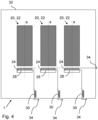
- Fig. 4 conceptually shows the transformer arrangement 1 comprising a three-phase transformer 10.
- a multi-phase transformer 10 may have an auxiliary winding 28 arranged around each limb 18.
- the limbs 18 are not shown in Fig. 4 , but it is to be understood that a first and second windings 20, 22 are arranged on a respective limb 18 for each phase of the transformer 10.
- each auxiliary winding 28 has a series reactor 30 connected in series.
- the transformer arrangement 1 may further comprise a transformer tank 32, and the transformer 10 may be enclosed in the transformer tank 32 and be immersed in insulating oil in the transformer tank 32.
- the series reactor 30 may be located inside the transformer tank 32. Thereby the series reactor 30 does not add to the size of the transformer 10, as opposed to a conventional medium voltage cabinet for short-circuit current protection, as discussed in the background section herein above. Terminals 34 of any auxiliary windings 28 may be led to the outside of the transformer tank 32.
- three-phase transformers 10 may be connected in star configuration or delta configuration.
- Auxiliary windings 28, each connected to a respective series reactor 30, of such three-phase configurations may correspondingly be connected in star configuration or delta configuration.
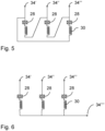
- Fig. 5 shows three auxiliary windings 28 of a three-phase transformer arrangement 1, which auxiliary windings 28 are connected in delta configuration.
- Terminals 34', 34", 34′′′ indicate terminals for the three phases which may be connected to deliver power to auxiliary systems.
- Fig. 6 shows three auxiliary windings 28 of a three-phase transformer arrangement 1, which auxiliary windings 28 are connected in star configuration.
- Terminals 34', 34", 34′′′ indicate terminals for the three phases which may be connected to deliver power to auxiliary systems.
- Terminal 34 ⁇ illustrate the neutral point of the star configuration.
- the star configuration is also known as a Y configuration or a wye configuration.
Landscapes
- Engineering & Computer Science (AREA)
- Power Engineering (AREA)
- Coils Of Transformers For General Uses (AREA)
Abstract
The disclosure relates to a transformer arrangement (1) having at least one transformer (10) comprising a transformer core (12), which transformer core (12) comprises a bottom yoke (14) and a top yoke (16) interconnected by at least one limb (18) extending along a first axis (a). At least a first winding (20) and a second winding (22) are coaxially arranged around the at least one limb (18). An auxiliary winding (28) is arranged around the at least one limb (18), positioned axially between the first and second windings (20, 22), and the bottom yoke (14) or the top yoke (16). The auxiliary winding is magnetically coupled to the at least first winding (20) and/or the second winding (22). The transformer arrangement (1) further comprises a series reactor (30) connected to the auxiliary winding (28).
Description
- The present disclosure relates to a transformer arrangement having an auxiliary winding. In particular, the disclosure relates to limiting short-circuit currents in such auxiliary windings.
- In conventional transformers, when auxiliary power is needed, an auxiliary winding such as a tertiary winding may be coaxially arranged with the main windings, i.e. with the primary and secondary windings. See
Fig. 1 . The auxiliary winding may for instance be used to supply power to devices at a transformer station, such as lighting, heating and cooling at the transformer station. Auxiliary windings are particularly useful in remote places which lack access to regular grid power. Tertiary winding arrangements add to the radial size of the transformer windings and to the transformer as a whole. It also adds to the cost of the transformer. Another type of auxiliary winding is a yoke winding, i.e. an auxiliary winding arranged around a yoke of the transformer. As an auxiliary winding, such a yoke winding is smaller, lighter and less expensive when compared to a coaxial tertiary winding. - Yoke windings have traditionally had a voltage level below 1kV which may be considered a low voltage application. Lately, yoke windings have been used at around 7 kV, which may be considered a medium voltage application. In medium voltage applications a cabinet external to the transformer is required. The cabinet comprises a fuse protecting the auxiliary winding from high short-circuit currents since the auxiliary winding is not inherently short-circuit proof. However, external cabinets require extra work and maintenance on site.
- Therefore, an object of the disclosure is to provide an improved transformer arrangement having an auxiliary winding which is protected from damaging short-circuit currents. In particular, the auxiliary winding is a yoke winding and the transformer arrangement does not require a cabinet.
- According to a first aspect of the present disclosure, the object is at least partly achieved by a transformer arrangement according to
claim 1. - Hence, there is provided a transformer arrangement having at least one transformer comprising a transformer core, which comprises a bottom yoke and a top yoke interconnected by at least one limb extending along a first axis. The transformer arrangement further comprises at least a first winding and a second winding coaxially arranged around the at least one limb. Further, an auxiliary winding is arranged around the at least one limb and is positioned axially between the first and second windings, and the bottom yoke or the top yoke. The auxiliary winding is magnetically coupled to the at least first winding and/or the second winding. The transformer arrangement further comprises a series reactor connected to the auxiliary winding.
- The first axis may be substantially vertically aligned. The auxiliary winding is positioned around the limb between an axial end of the first and second windings and the top or bottom yoke, i.e. axially between the first and second windings and the top or bottom yoke. The auxiliary winding is positioned such that it is magnetically coupled to the first and second windings and configured deliver a part of the power of the main windings to at least one auxiliary device.
- When the transformer is a multi-phase transformer, such as a three-phase transformer, the transformer comprises multiple limbs, e.g. one limb per phase. Each limb may be provided with an auxiliary winding, resulting in a three-phase power supply for auxiliary equipment and devices. Obviously, each auxiliary winding may be connected to a respective series reactor.
- The series reactor comprises at least one impedance element connected in series with the auxiliary winding. The reactor is passive during normal operation of the auxiliary winding. At the occurrence of a short-circuit event in the auxiliary winding, a suddenly increased current through the reactor generates a magnetic field which induces an opposed current in the reactor, which in turn reduces and limits the short-circuit current.
- Optionally, the auxiliary winding is configured to deliver auxiliary power from the transformer via the series reactor to at least one auxiliary device.
- The auxiliary winding is magnetically coupled to the first and second windings of the transformer. Power may thereby be generated in the auxiliary winding and delivered to auxiliary devices and equipment. Such devices and equipment may be power consumers used locally at a transformer station, e.g. devices for lighting, heating and/or cooling, such as when the transformer station is in a remote location and is not connected to a grid which could supply the devices. The auxiliary winding is dimensioned and configured to deliver power at a voltage level suitable for the auxiliary devices.
- Optionally, the transformer arrangement further comprises at least one support element positioned between an axial end of the first and second windings and the bottom yoke and/or the top yoke. The auxiliary winding may be supported by the support element.
- The support element is an element configured to mechanically support the windings. The support element may be formed of an electrically insulating material and may be in physical contact with the windings. The support element may for example be a so-called common spacer ring.
- In case the auxiliary winding is positioned below an axial lower end of the first and second windings, the support element may be supported on the bottom yoke and the auxiliary winding may be supported by the support element on an upper side of the support element.
- In case the auxiliary winding is positioned above an axial upper end of the first and second windings, the auxiliary winding may be supported by the support element on an upper side of the support element.
- Optionally, the support element is a ring comprising an annular groove, which annular groove circumscribes the limb. The auxiliary winding may be arranged in the annular groove.
- As such, the auxiliary winding is assembled with the transformer without increasing its size, since the auxiliary winding is housed in an existing component, i.e. in the groove of the support element.
- Optionally, a rated power of at least the first winding or the second winding is above 100 MVA and the rated voltage of at least the first winding or the second winding is above 66 kV.
- Optionally, the auxiliary winding has a rated voltage above 1 kV.
- Optionally, an impedance of the series reactor is configured to limit short-circuit currents in the auxiliary winding below 30kA rms.
- Optionally, the at least one transformer is a three-phase transformer or three single-phase transformers and wherein three auxiliary windings, each connected to a respective series reactor, are connected in star configuration or in delta configuration.
- The star connection is also known as Y connection or wye connection.
- Optionally, the transformer arrangement further comprises a transformer tank, wherein the transformer is enclosed in the transformer tank and is immersed in oil in the transformer tank.
- Optionally, the series reactor is located inside the transformer tank. Thereby the series reactor does not add to the size of the transformer, as opposed to a conventional medium voltage cabinet for short-circuit current protection, as discussed in the background section herein above. Terminals of any auxiliary windings may be led to the outside of the transformer tank. A star or delta configuration of the auxiliary windings may be connected inside the transformer tank enclosing a three-phase transformer. In case of three single-phase transformers, each transformer enclosed in a respective transformer tank, the star or delta configuration of the auxiliary windings is connected outside the transformer tanks.
- The above aspects, accompanying claims, and/or examples disclosed herein above and later below may be suitably combined with each other as would be apparent to anyone of ordinary skill in the art.
- Additional features and advantages are disclosed in the following description, claims, and drawings, and in part will be readily apparent therefrom to those skilled in the art or recognized by practicing the disclosure as described herein.
- Further objects and advantages of, and features of the disclosure will be apparent from the following description of one or more embodiments, with reference to the appended drawings, where:
- Fig. 1
- shows cross-sectional view of a prior art transformer arrangement comprising a tertiary winding as an auxiliary winding.
- Fig. 2
- shows a cross-sectional view of a transformer arrangement according to a first aspect of the present disclosure.
- Fig. 3
- shows a cross-sectional view of a transformer arrangement according to an embodiment of the present disclosure.
- Fig. 4
- conceptually shows an exemplary three-phase transformer according to an embodiment the present disclosure.
- Fig. 5
- shows an example of an embodiment of the present disclosure for a transformer connected in delta configuration.
- Fig. 6
- shows an example of an embodiment of the present disclosure for a transformer connected in star configuration.
- The present disclosure is developed in more detail below referring to the appended drawings which show examples of embodiments. The disclosure should not be viewed as limited to the described examples of embodiments. Like numbers refer to like elements throughout the description.
- The terminology used herein is for the purpose of describing particular aspects of the disclosure only and is not intended to limit the invention. As used herein, the singular forms "a", "an" and "the" are intended to include the plural forms as well, unless the context clearly indicates otherwise. Unless otherwise defined, all terms (including technical and scientific terms) used herein have the same meaning as commonly understood by one of ordinary skill in the art to which this disclosure belongs.
-
Fig. 1 illustrates a cross-sectional view of a prior art transformer 10' comprising atransformer core 12 having abottom yoke 14 and atop yoke 16 interconnected by alimb 18 extending along a first axis a. A inner first winding 20 and an outer second winding 22 are coaxially arranged around thelimb 18. An auxiliary winding 23 in the form of a tertiary winding is coaxially arranged with the first andsecond windings limb 18. The auxiliary/tertiary winding 23 is magnetically coupled to the at least first winding 20 and/or the second winding 22. A tertiary winding 23, such as shown inFig. 1 , may be designed to withstand short-circuit currents. - According to an aspect of the present disclosure, the tertiary winding 23 as an auxiliary winding may be replaced by a yoke winding 28, as shown in
Fig. 2 . The yoke winding is attractive in that it is smaller, lighter and less expensive than a tertiary winding 23 which is conventionally arranged coaxially with the first andsecond windings - The present disclosure makes the cabinet unnecessary and results in a
transformer arrangement 1 comprising atransformer 10 having an auxiliary winding 28, whichtransformer arrangement 1 smaller or similar in size to a conventional transformer 10' having a tertiary winding. -
Fig. 2 shows thetransformer arrangement 1 having at least onetransformer 10. The transformer arrangement comprises atransformer core 12 comprising abottom yoke 14 and atop yoke 16 interconnected by at least one limb (18) extending along a first axis a. At least a first winding 20 and a second winding 22 are coaxially arranged around the at least onelimb 18. An auxiliary winding 28 is arranged around the at least onelimb 18, positioned axially between the first andsecond windings bottom yoke 14 or thetop yoke 16. The auxiliary winding is magnetically coupled to the at least first winding 20 and/or the second winding 22. Thetransformer arrangement 1 further comprises aseries reactor 30 connected to the auxiliary winding 28. - The first axis a may be substantially vertically aligned. The auxiliary winding 28 is positioned around the
limb 18 between an axial end of the first andsecond windings top yoke 16 orbottom yoke 14, i.e. axially between the first andsecond windings top yoke 16 orbottom yoke 14. The auxiliary winding 18 is positioned such that it is magnetically coupled to the first andsecond windings second windings 20, 22) to at least one auxiliary device (not shown). - When the
transformer 10 is amulti-phase transformer 10, such as a three-phase transformer 10, thetransformer 10 comprisesmultiple limbs 18, e.g. one limb perphase 18. Eachlimb 18 may be provided with an auxiliary winding 28, resulting in a three-phase power supply for auxiliary equipment and devices. Each auxiliary winding 28 may be connected to arespective series reactor 30. - The
series reactor 30 comprises at least one impedance element connected in series with the auxiliary winding. The series reactor is passive during normal operation of the auxiliary winding 28. At the occurrence of a short-circuit event in the auxiliary winding 28, a suddenly increased current through theseries reactor 30 generates a magnetic field which induces an opposed current in theseries reactor 30, which in turn reduces and limits the short-circuit current in both the series reactor and, more importantly, in the auxiliary winding 28. - The auxiliary winding 28 may be configured to deliver auxiliary power from the
transformer 10 via theseries reactor 30 to at least one auxiliary device viaterminals 34. The auxiliary winding 28 is magnetically coupled to the first andsecond windings transformer 10. Power may thereby be generated in the auxiliary winding 28 and delivered to auxiliary devices and equipment. Such devices and equipment may be power consumers used locally at a transformer station, e.g. devices for lighting, heating and/or cooling, such as when the transformer station is in a remote location and is not connected to a grid which could supply the devices. The auxiliary winding 28 is dimensioned and configured to deliver power at a voltage level suitable for such auxiliary devices. -
Fig. 3 illustrates that thetransformer arrangement 1 may further comprise at least onesupport element 24 positioned between an axial end of the first andsecond windings bottom yoke 14 and/or thetop yoke 16. The auxiliary winding 28 may be supported by thesupport element 24. - The
support element 24 is an element configured to mechanically support the first andsecond windings support element 24 may be formed of an electrically insulating material and may be in physical contact with the first andsecond windings support element 24 may for example be a so-calledcommon spacer ring 24. - In case the auxiliary winding 28 is positioned below an axial lower end of the first and
second windings support element 24 may be supported on thebottom yoke 14 and the auxiliary winding 28 may be supported by thesupport element 24 on an upper side of thesupport element 24. - In case the auxiliary winding 28 is positioned above an axial upper end of the first and
second windings support element 24 on an upper side of thesupport element 24. - The support element may be a
ring 24 comprising anannular groove 25, whichannular groove 25 circumscribes thelimb 18. The auxiliary winding 28 may be arranged in theannular groove 25. The auxiliary winding 28 may thereby be assembled with thetransformer 10 without increasing the size of thetransformer 10, since the auxiliary winding 28 is housed in an existing component, i.e. in thegroove 25 of thesupport element 24. Terminals - When the at least one auxiliary winding 28 is used for medium voltage applications, a rated power of the at least one first winding 20 or the second winding 22 is above 100MVA and the rated voltage of at least the first winding 20 or the second winding 22 is above 66kV. The auxiliary winding has a rated voltage above 1kV. In order to protect the auxiliary winding 28 from damage due to short-circuit currents, an impedance of the
series reactor 30 is preferably configured to limit short-circuit currents in the auxiliary winding 28 below 30kA rms. -
Fig. 4 conceptually shows thetransformer arrangement 1 comprising a three-phase transformer 10. As shown, amulti-phase transformer 10 may have an auxiliary winding 28 arranged around eachlimb 18. Thelimbs 18 are not shown inFig. 4 , but it is to be understood that a first andsecond windings respective limb 18 for each phase of thetransformer 10. In addition, and in accordance with the present disclosure, each auxiliary winding 28 has aseries reactor 30 connected in series. - The
transformer arrangement 1 may further comprise atransformer tank 32, and thetransformer 10 may be enclosed in thetransformer tank 32 and be immersed in insulating oil in thetransformer tank 32. Theseries reactor 30 may be located inside thetransformer tank 32. Thereby theseries reactor 30 does not add to the size of thetransformer 10, as opposed to a conventional medium voltage cabinet for short-circuit current protection, as discussed in the background section herein above.Terminals 34 of anyauxiliary windings 28 may be led to the outside of thetransformer tank 32. - As is known in the art, three-
phase transformers 10 may be connected in star configuration or delta configuration.Auxiliary windings 28, each connected to arespective series reactor 30, of such three-phase configurations may correspondingly be connected in star configuration or delta configuration. -
Fig. 5 shows threeauxiliary windings 28 of a three-phase transformer arrangement 1, whichauxiliary windings 28 are connected in delta configuration.Terminals 34', 34", 34‴ indicate terminals for the three phases which may be connected to deliver power to auxiliary systems. -
Fig. 6 shows threeauxiliary windings 28 of a three-phase transformer arrangement 1, whichauxiliary windings 28 are connected in star configuration.Terminals 34', 34", 34‴ indicate terminals for the three phases which may be connected to deliver power to auxiliary systems. Terminal 34ʺʺ illustrate the neutral point of the star configuration. As stated above, the star configuration is also known as a Y configuration or a wye configuration.
Claims (10)
- A transformer arrangement (1) having at least one transformer (10) comprising:- a transformer core (12) comprising a bottom yoke (14) and a top yoke (16) interconnected by at least one limb (18) extending along a first axis (a),- at least a first winding (20) and a second winding (22) coaxially arranged around the at least one limb (18),- an auxiliary winding (28) arranged around the at least one limb (18), positioned axially between the first and second windings (20, 22), and the bottom yoke (14) or the top yoke (16), the auxiliary winding being magnetically coupled to the at least first winding (20) and/or the second winding (22), andwherein the transformer arrangement (1) further comprises a series reactor (30) connected to the auxiliary winding (28).
- The transformer arrangement (1) according to claim 1, wherein the auxiliary winding (28) is configured to deliver auxiliary power from the transformer (10) via the series reactor (30) to at least one auxiliary device.
- The transformer arrangement (1) according to any one of claims 1-2, further comprising at least one support element (24) positioned between an axial end of the first and second windings and the bottom yoke (14) and/or the top yoke (16), wherein the auxiliary winding (28) is supported by the support element (24).
- The transformer arrangement (1) according to claim 3, wherein the support element is a ring (24) comprising an annular groove (25), which annular groove (25) circumscribes the limb (18), and wherein the auxiliary winding (28) is arranged in the annular groove (25).
- The transformer arrangement (1) according to any one of the previous claims, where a rated power of at least the first winding (20) or the second winding (22) is above 100MVA and the rated voltage of the first winding (20) and wherein a rated voltage of at least the first winding (20) or the second winding (22) is above 66kV.
- The transformer arrangement (1) according to any one of the previous claims, wherein the auxiliary winding (28) has a rated voltage above 1 kV.
- The transformer arrangement (1) according to any one of the previous claims, wherein an impedance of the series reactor (30) is configured to limit short-circuit currents in the auxiliary winding below 30kA rms (28).
- The transformer arrangement (1) according to any one of the previous claims, wherein the at least one transformer (10) is a three-phase transformer (10) or three single-phase transformers (10) and wherein three auxiliary windings (28), each connected to a respective series reactor (30), are connected in star configuration or in delta configuration.
- The transformer arrangement (1) according to any one of the previous claims, further comprising a transformer tank (32), wherein the transformer (10) is enclosed in the transformer tank (32) and is immersed in oil in the transformer tank (32).
- The transformer arrangement (1) according to claim 9, wherein the series reactor (30) is located inside the transformer tank (32).
Priority Applications (5)
| Application Number | Priority Date | Filing Date | Title |
|---|---|---|---|
| EP23170439.6A EP4456097A1 (en) | 2023-04-27 | 2023-04-27 | A transformer arrangement |
| CN202480028454.1A CN121058072A (en) | 2023-04-27 | 2024-04-26 | Transformer layout |
| PCT/EP2024/061648 WO2024223886A1 (en) | 2023-04-27 | 2024-04-26 | A transformer arrangement |
| US19/478,515 US20260120944A1 (en) | 2023-04-27 | 2024-04-26 | A transformer arrangement |
| EP24722278.9A EP4702582A1 (en) | 2023-04-27 | 2024-04-26 | A transformer arrangement |
Applications Claiming Priority (1)
| Application Number | Priority Date | Filing Date | Title |
|---|---|---|---|
| EP23170439.6A EP4456097A1 (en) | 2023-04-27 | 2023-04-27 | A transformer arrangement |
Publications (1)
| Publication Number | Publication Date |
|---|---|
| EP4456097A1 true EP4456097A1 (en) | 2024-10-30 |
Family
ID=86272098
Family Applications (2)
| Application Number | Title | Priority Date | Filing Date |
|---|---|---|---|
| EP23170439.6A Pending EP4456097A1 (en) | 2023-04-27 | 2023-04-27 | A transformer arrangement |
| EP24722278.9A Pending EP4702582A1 (en) | 2023-04-27 | 2024-04-26 | A transformer arrangement |
Family Applications After (1)
| Application Number | Title | Priority Date | Filing Date |
|---|---|---|---|
| EP24722278.9A Pending EP4702582A1 (en) | 2023-04-27 | 2024-04-26 | A transformer arrangement |
Country Status (4)
| Country | Link |
|---|---|
| US (1) | US20260120944A1 (en) |
| EP (2) | EP4456097A1 (en) |
| CN (1) | CN121058072A (en) |
| WO (1) | WO2024223886A1 (en) |
Citations (4)
| Publication number | Priority date | Publication date | Assignee | Title |
|---|---|---|---|---|
| US20100208394A1 (en) * | 2009-02-19 | 2010-08-19 | Chien-Liang Lin | Power converter and method thereof |
| US20160300662A1 (en) * | 2013-12-10 | 2016-10-13 | Siemens Aktiengesellschaft | Device and Method for Reducing a Magnetic Unidirectional Flux Component of a Transformer Core |
| CN206921642U (en) * | 2017-06-12 | 2018-01-23 | 美桀电子科技(深圳)有限公司 | A kind of transformer |
| DE102021200066A1 (en) * | 2021-01-07 | 2022-07-07 | Robert Bosch Gesellschaft mit beschränkter Haftung | WELDING TRANSFORMER, WELDING DEVICE AND WELDING PROCESS FOR WELDING AT LEAST ONE COMPONENT |
-
2023
- 2023-04-27 EP EP23170439.6A patent/EP4456097A1/en active Pending
-
2024
- 2024-04-26 WO PCT/EP2024/061648 patent/WO2024223886A1/en not_active Ceased
- 2024-04-26 EP EP24722278.9A patent/EP4702582A1/en active Pending
- 2024-04-26 CN CN202480028454.1A patent/CN121058072A/en active Pending
- 2024-04-26 US US19/478,515 patent/US20260120944A1/en active Pending
Patent Citations (4)
| Publication number | Priority date | Publication date | Assignee | Title |
|---|---|---|---|---|
| US20100208394A1 (en) * | 2009-02-19 | 2010-08-19 | Chien-Liang Lin | Power converter and method thereof |
| US20160300662A1 (en) * | 2013-12-10 | 2016-10-13 | Siemens Aktiengesellschaft | Device and Method for Reducing a Magnetic Unidirectional Flux Component of a Transformer Core |
| CN206921642U (en) * | 2017-06-12 | 2018-01-23 | 美桀电子科技(深圳)有限公司 | A kind of transformer |
| DE102021200066A1 (en) * | 2021-01-07 | 2022-07-07 | Robert Bosch Gesellschaft mit beschränkter Haftung | WELDING TRANSFORMER, WELDING DEVICE AND WELDING PROCESS FOR WELDING AT LEAST ONE COMPONENT |
Non-Patent Citations (1)
| Title |
|---|
| "IEEE Guide for the Application of Tertiary and Stabilizing Windings in Power Transformers", IEEE STANDARD, 27 April 2018 (2018-04-27), pages 1 - 80, XP068124984, ISBN: 978-1-5044-4629-7, [retrieved on 20180428], DOI: 10.1109/IEEESTD.2018.8352755 * |
Also Published As
| Publication number | Publication date |
|---|---|
| CN121058072A (en) | 2025-12-02 |
| EP4702582A1 (en) | 2026-03-04 |
| WO2024223886A1 (en) | 2024-10-31 |
| US20260120944A1 (en) | 2026-04-30 |
Similar Documents
| Publication | Publication Date | Title |
|---|---|---|
| US20010019494A1 (en) | Dc transformer/reactor | |
| CA2255742A1 (en) | A dc transformer/reactor | |
| CN107210122B (en) | System for the protection of dry-type transformers | |
| AU2010214736B2 (en) | High voltage fault current limiter having immersed phase coils | |
| KR20010092749A (en) | Electrical Power Transmission System Using Superconductors | |
| US9953760B2 (en) | Transformer arrangement for mitigating transient voltage oscillations | |
| US20260120944A1 (en) | A transformer arrangement | |
| EP3400602A1 (en) | Multilayer winding transformer | |
| Hoerauf et al. | Avoiding potential transformer ferroresonant problems in industrial power systems | |
| WO2018028875A1 (en) | Surge arresters for power transformer | |
| KR20000016097A (en) | Direct current transformer and reactor | |
| Rosa | HV Sshunt Reactors: An Overall Comparative Analysis Between Dry-Type Air Core and Oil-Immersed Iron Core Technologies | |
| EP3933862B1 (en) | Transformer arrangement and method for electrically connecting and disconnecting a transformer | |
| JP2020038926A (en) | Dry transformer | |
| WO2024041734A1 (en) | Protection arrangement for a transformer | |
| JPH11299088A (en) | AC current suppressor | |
| Ilie et al. | Issues to consider when substituting large power transformers in generating stations | |
| Radu et al. | THE PROCESSES USED IN PROTECTION OF SYNCHRONOUS GENERATORS IN NAVAL ELECTRICAL NETWORKS | |
| Wright | Application of fuses to power-system equipment | |
| US20030020352A1 (en) | Generator for producing high voltages | |
| JP2004111537A (en) | Transformers and distribution equipment | |
| JPH11111509A (en) | Lightning arrester | |
| CN110100364A (en) | The protection of inductance element | |
| MXPA99005677A (en) | Device and method relating to protection of an object against over-currents comprising over-current reduction and current limitation | |
| JPH06196337A (en) | Disassembling and transporting method for transformer |
Legal Events
| Date | Code | Title | Description |
|---|---|---|---|
| PUAI | Public reference made under article 153(3) epc to a published international application that has entered the european phase |
Free format text: ORIGINAL CODE: 0009012 |
|
| STAA | Information on the status of an ep patent application or granted ep patent |
Free format text: STATUS: THE APPLICATION HAS BEEN PUBLISHED |
|
| AK | Designated contracting states |
Kind code of ref document: A1 Designated state(s): AL AT BE BG CH CY CZ DE DK EE ES FI FR GB GR HR HU IE IS IT LI LT LU LV MC ME MK MT NL NO PL PT RO RS SE SI SK SM TR |
|
| STAA | Information on the status of an ep patent application or granted ep patent |
Free format text: STATUS: REQUEST FOR EXAMINATION WAS MADE |
|
| 17P | Request for examination filed |
Effective date: 20250416 |