EP4456038A1 - Method for detecting potential-only-acknowledge situations in to intersection area in road traffic and vehicle - Google Patents
Method for detecting potential-only-acknowledge situations in to intersection area in road traffic and vehicle Download PDFInfo
- Publication number
- EP4456038A1 EP4456038A1 EP23169874.7A EP23169874A EP4456038A1 EP 4456038 A1 EP4456038 A1 EP 4456038A1 EP 23169874 A EP23169874 A EP 23169874A EP 4456038 A1 EP4456038 A1 EP 4456038A1
- Authority
- EP
- European Patent Office
- Prior art keywords
- vehicle
- state
- state machine
- road user
- road
- Prior art date
- Legal status (The legal status is an assumption and is not a legal conclusion. Google has not performed a legal analysis and makes no representation as to the accuracy of the status listed.)
- Pending
Links
Images
Classifications
-
- G—PHYSICS
- G08—SIGNALLING
- G08G—TRAFFIC CONTROL SYSTEMS
- G08G1/00—Traffic control systems for road vehicles
- G08G1/16—Anti-collision systems
- G08G1/166—Anti-collision systems for active traffic, e.g. moving vehicles, pedestrians, bikes
-
- G—PHYSICS
- G08—SIGNALLING
- G08G—TRAFFIC CONTROL SYSTEMS
- G08G1/00—Traffic control systems for road vehicles
- G08G1/09—Arrangements for giving variable traffic instructions
- G08G1/0962—Arrangements for giving variable traffic instructions having an indicator mounted inside the vehicle, e.g. giving voice messages
- G08G1/0968—Systems involving transmission of navigation instructions to the vehicle
- G08G1/0969—Systems involving transmission of navigation instructions to the vehicle having a display in the form of a map
-
- G—PHYSICS
- G08—SIGNALLING
- G08G—TRAFFIC CONTROL SYSTEMS
- G08G1/00—Traffic control systems for road vehicles
- G08G1/16—Anti-collision systems
- G08G1/161—Decentralised systems, e.g. inter-vehicle communication
- G08G1/163—Decentralised systems, e.g. inter-vehicle communication involving continuous checking
Definitions
- the invention relates to a method for detecting potentially dangerous situations in an intersection area in road traffic, wherein a vehicle communicates with further road users by means of Car2X communication and/or wherein the vehicle communicates with at least part of a road traffic infrastructure by means of Car2X communication, wherein in the Car2-X communication information about status data of the vehicle and information about status data of the other road users are transmitted and wherein the status data are linked with navigation data, in particular with coordinates, in such a way that a prediction of a future route of the vehicle and of the other road users is made possible.
- the invention relates to a vehicle, in particular a motor vehicle, with an evaluation unit and with a display device with at least one display area.
- Today's driver assistance systems which rely on sensors installed on the vehicle, warn of a concrete collision only at a very late stage. When the system is triggered, it warns of a concrete danger or intervenes in the driving dynamics. In procedures that directly link the warning level of a driver interface to a condition that is to occur, for example whether any object is on a collision course, mechanisms such as a decay time are often implemented in order not to warn of the same object again as long as the condition continues to be fulfilled.
- the invention is therefore based on the task of providing a method for recognising potentially dangerous situations in an intersection area in road traffic and a vehicle, in which anticipatory information about potential dangers is made possible, whereby attention can be directed to several objects at the same time.
- this task is firstly solved by the features of the identification part of patent claim 1 in that a state machine is defined for the vehicle, in that at least one further state machine is defined for at least one further road user, it being possible to define different states for the state machines, and in that at least one warning state is defined.
- Car2X data is a technology in which vehicles communicate with their environment, i.e. "X".
- vehicles can also communicate with each other.
- transmission is possible in both directions. Consequently, the vehicle can communicate with the environment and/or the environment with the vehicle.
- sensor data is transmitted during communication.
- the Car2X communication is realised via a WLAN connection.
- WLANp IEEE 802.11p
- other technologies e.g. C-V2X (LTE-V2X, 5G-V2X) or backend communication are also conceivable.
- Examples are the CAM (Cooperative Awareness Message), or DENM (Decentralised Environmental Notification Message) and/or Plus VAM (Vulnerable Road User Awareness Message) und CPM (Collective Perception Message) of the ETSI standard for Car2X communication.
- Vehicles can communicate with other vehicles via Car2X communication. By communicating with each other, vehicles can communicate their positions with each other. By linking with an environmental sensor system, for example, the position of the vehicle can be determined more clearly.
- the vehicle can communicate with the infrastructure via Car2X communication.
- the infrastructure can be traffic lights or, for example, cameras used to monitor road traffic.
- An intersection is a section of road traffic where at least two roadways cross. This can refer to roadways used by motor vehicles as well as roadways used by other road users, such as cyclists or pedestrians.
- a crossing area can therefore also be a straight road with a pedestrian crossing or a cycle path that crosses the road.
- the status data can be various data of the vehicle or the other vehicles.
- states are physical properties that the vehicle has at a certain moment. These include, for example, the speed, the direction of travel, the acceleration and comparable values, and/or preferably the relative position of the vehicle.
- the navigation data can preferably be provided by means of GPS, but also by means of positioning sensors.
- Prediction is a prediction of the future route of the vehicle.
- the future route can be predicted on the basis of various criteria.
- the navigation data which provide information about the condition of the road network, are linked to the status data of the vehicle or the other vehicles, so that the reaching of certain points can be represented by means of time-dependent coordinates.
- the prediction of the route can be calculated probabilistically or discretely.
- road users are in particular those road users who are in the vicinity of the vehicle. These are vehicles moving in the statutory direction of travel in the lane occupied by the vehicle. However, it is also conceivable that other vehicles are part of the oncoming traffic, for example. Other road users can also be cyclists or pedestrians.
- the travel distance is the future distance to be covered by the vehicle or other road users, especially on a road.
- the longitudinal movement on the road is taken into account, but also the lateral movement of the vehicle on the road. Consequently, the distance travelled is not only to be understood as the distance travelled on a road, for example, but also the lateral movement, i.e. the position of the vehicle in relation to the entire width of the road or the width of the road.
- the lateral movement i.e. the position of the vehicle in relation to the entire width of the road or the width of the road.
- there are often narrowed lanes so that driving is only possible in a certain area of the entire theoretically available width of the lane.
- the state machine can be a finite automaton that represents a model of behaviour consisting of states, state transitions and actions.
- the state machine is finite because the number of states it can assume is predefined.
- a state can contain information about the past, since the system has reached it along its previous path. This means that it reflects to a certain extent the changes in the input since the start of the system up to the current time.
- the state can also be defined by or contain the aforementioned state data.
- An advantage of the method according to the invention is that attention can be directed to several objects, whereby information about the relevance of each object in the current situation can be made available to the driver of a vehicle, for example via an interface.
- the state machine for the vehicle and/or the state machine for another road user is brought into the warning state if it is determined that the future travel path of the vehicle intersects with a future travel path of at least one other road user.
- the warning state can be used to warn of potentially dangerous situations. If a future path of the vehicle will intersect with another road user, a collision of the two vehicles is very likely if no further action is taken. With the information that another road user in the vicinity has caused a warning condition, a driver of the vehicle can anticipate and react to the increased danger.
- a state of awareness is defined and that the state machine for the vehicle and/or the state machine for another road user is brought into the state of awareness if it is determined that the future travel path of the vehicle intersects with a future travel path of at least one other road user and predefined threshold is exceeded.
- Triggering criteria for the threshold can be a purely geometric overlap of the paths (paths cross), a geometric and temporal overlap (paths cross at approximately the same time) or certain overlap probabilities (paths cross with a defined probability at the same time).
- the awareness state is a weaker state in criticality than the warning state. If the distance is still large enough, i.e.
- the distance to the crossing point of the two future travel paths is greater than the predetermined limit distance, on the one hand the predicted travel path can still change, and on the other hand there is still sufficient time to react adequately to the situation.
- the state machine of the vehicle and/or of the other road user is brought into the warning state if the future travel path of the vehicle intersects with a future travel path of at least one other road user and a predefined second threshold is exceeded.
- the triggering of the warning state behaves similarly to the triggering of the awareness state, but here a different (sharper) parameterization applies.
- a neutral state is defined and that the state machine for a further road user is placed in the neutral state if it is determined that the future travel path of the vehicle does not intersect with a future travel path of the further road users.
- the neutral state is a weaker state in criticality than the awareness state. In the neutral state, there is no or no great potential for a dangerous situation. Other road users whose state machine has been placed in the neutral state are not cause of a dangerous situation. It is conceivable that the state machines are in the neutral state by default until a condition for changing the state is fulfilled.
- an exit state is defined and that the state machine for the vehicle is brought into the exit state when the vehicle moves away from a predefined conflict area.
- the state machine of the vehicle and/or of the at least one other road user is only brought into the warning state if the vehicle and/or the other road user is moving towards a predefined conflict area.
- criteria in which one state is brought into another state An example is the change of state only if the object with a corresponding state machine actually moves towards a conflict area, i.e. can cause a potentially dangerous situation.
- the state machine for the vehicle can only switch to the awareness state and the warning state if a) at least one object, i.e. other road users, is in the awareness state or warning state, b) the necessary condition that the state machine for the vehicle was previously in "Active” is fulfilled. To reach "Active” again, the vehicle must move towards the intersection area.
- the states of the state machines are ordered according to criticality and that the state machine for the vehicle is transferred to the most critical state if it is detected that the state machine of another road user has already been transferred to the most critical state.
- the states are thus aggregated at a suitable point and thereby evaluated using the example of a minimum function.
- the state machine of the vehicle is consequently brought into the state with the highest criticality, for example into the warning state, if at least one state machine of a further road user is in the warning state. It can be summarized that there are circumstances that influence the state of the state machine of the vehicle, such as whether the vehicle is approaching the intersection.
- the state machine of the vehicle is in the activated state ("Active") as a result, then the severity of the actual warning state in the state machine of the vehicle (Awareness or Warning) is determined by the highest warning state of all existing objects with Object State Machine.
- the driver of the vehicle is signalled when a state machine is in a warning state.
- the signalling can be acoustic and/or visual. Haptic feedback, for example through vibrations on the steering wheel, would also be conceivable.
- the vehicle comprises a display device with at least one display area, that the position of the vehicle and that of the other road user can be displayed on a virtual map in the display area.
- the display area of the display device can be a display in the centre area or in the cockpit area, for example in the instrument cluster of the vehicle.
- the display area of the display device can be designed as a head-up display.
- Head-up display means a display area in which the driver can maintain his head position or viewing direction because the information is projected into his field of vision, for example onto the windscreen of the vehicle. In this way, the driver of the vehicle is visually warned that the predicted future path of travel will intersect with the future path of travel of another road user, in particular an unprotected road user, unless appropriate action is taken to prevent this.
- the other road users who are in a state selected by the driver of the vehicle are displayed in the display area. It can be provided that the other road users are highlighted. Highlighting draws the attention of the driver of the vehicle, for example, to the object whose future route will intersect with the vehicle when the driver of the vehicle selects further road users who are in a warning state. If the vehicle and the further road user are virtually displayed in the display area of the display device analogously to their actual position, the driver of the vehicle can estimate from which direction the further road user will cross the path of the vehicle and can react accordingly to avoid a collision. Highlighting can be done, for example, by colouring the other road users in a signal colour. It is also conceivable that the other road users are displayed enlarged and/or flashing or pulsating.
- a decay time is defined for the state machine of the vehicle and/or the other road users, after which the state machine of the vehicle and/or the state machine of the other road users are brought into another state if a condition for changing the state is fulfilled.
- the decay time or a waiting time can prevent warnings from being displayed repeatedly within a short period of time, but it still allows states to be maintained if an object triggering a warning is no longer relevant, but a subsequent or opposite object is.
- a vehicle in particular a motor vehicle, with an evaluation unit and with a display device with at least one display area. It is provided that a method according to the invention can be carried out by the evaluation unit. The above explanations concerning the method according to the invention also apply accordingly to the vehicle according to the invention.
- Electronic or electrical devices and/or other relevant devices or components according to embodiments of the present invention described herein may be implemented using any suitable hardware, firmware (e.g., an application-specific integrated circuit), software, or a combination of software, firmware and hardware.
- the various components of these devices may be located on an integrated circuit (IC) or on separate IC chips.
- the various components of these devices may be implemented on a flexible printed circuit film, a tape carrier package (TCP), a printed circuit board (PCB), or on a single substrate.
- the various components of these devices may be a process or thread running on one or more processors in one or more computing devices, executing computer program instructions and interacting with other system components to perform the various functions described herein.
- the computer program instructions are stored in memory that may be implemented in a computing device using standard memory, such as random access memory (RAM).
- the computer program instructions may also be stored in other non-transferable computer-readable media, such as a CD-ROM, flash drive or the like.
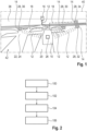
- Fig. 1 shows the implementation of a method for detecting potentially dangerous situations in an intersection area in road traffic.
- a vehicle 10 communicates with other road users 14 or part of an infrastructure 16 of the road traffic by means of Car2X communication 12.
- the infrastructure 16 is traffic lights and cameras for monitoring road traffic. It is envisaged that information about status data of the vehicle 10 and information about status data of the other road users 14 are transmitted during the Car2-X communication 12.
- the status data is linked with navigation data, in particular with coordinates, in such a way that a prediction of a future route 18 of the vehicle 10 and the other vehicles 14 is made possible.
- the status data contains information about the position and speed of the vehicle 10 or of the other road users 14. By using the information regarding the position, in the form of coordinates, and the current speed, conclusions can be drawn about the route of the vehicle 10 or of the other road users 14 in conjunction with navigation data containing information about the road layout, which makes it possible to predict the future route 18.
- the navigation data contains information about lanes 20. By knowing the lanes 20, in particular in the relevant intersection area, the positions of the vehicle 10 or of other road users 14 can be further specified. Furthermore, the navigation data contains information about pedestrian crossings 22 and bicycle crossings 24. In this way, the most probable routes of unprotected road users can already be taken into account. Thus, the prescribed paths can already be associated with the conditions of unprotected road users.
- the condition data contain information about a lane 20 on which the vehicle 10 or the other road users 14 are located. Thus, both the vehicle 10 and the other vehicles 14 can be clearly assigned to a lane 20. This information increases the accuracy of the position determination of the vehicle 10 or the other vehicles 14. In addition, the prediction of the future route 18 can be improved if, for example, it is recognised that a vehicle 10 is in a turning lane.
- a state machine 26 is defined for the vehicle 10.
- further state machines 28 are defined for at least one further road user 14, it being possible to define different states for the state machines 26, 28 and at least one warning state 30 being defined.
- the state machine 26 for the vehicle 10 and the further state machine 28 for a further road user 14 are brought into the warning state 30 when it is determined that the future travel path 18 of the vehicle 10 intersects with a future travel path 18 of at least one further road user 14.
- Warning state 30 may be used to warn of potentially dangerous situations. If a future path of travel 18 of the vehicle 10 will intersect with another road user 14, a collision between the two vehicles is highly likely should no further action be taken.
- a state of awareness 32 is further defined.
- the state machine 26 for the vehicle 10 and the further state machine 28 for a further road user 14 are placed in the awareness state 32 when it is determined that the future travel path 18 of the vehicle 10 intersects with a future travel path 18 of at least one further road user 14 and the distance of the intersection point is greater than a predetermined threshold distance.
- the awareness state 32 is a weaker state in criticality than the warning state 30. If the distance is still large enough, i.e. the distance to the intersection of the two future travel paths 18 is greater than the predetermined limit distance, on the one hand the predicted travel path can still change, and on the other hand there is still sufficient time to react adequately to the situation.
- a standby state 34 is defined and that the state machine 26 for the vehicle 10 and the further state machine 28 for a further road user 14 are placed in the standby state 34 when it is determined that the future path of travel 18 of the vehicle 10 does not intersect with a future path of travel 18 of the further road users 14.
- the standby state 34 is a weaker state in criticality than the awareness state 32. In the standby state 34 there is no or no great potential for a dangerous situation. Vehicles or other road users 14 whose state machine 26, 28 have been placed in standby state 34 are not in a dangerous situation.
- the state machines can be in the standby state by default until a condition for changing the state is fulfilled.
- an exit state 36 is defined.
- the state machine 26 for the vehicle 10 is brought into the exit state 36 if the vehicle 10 move a away from a predefined conflict area.
- the states of the state machines 26, 28 are ordered by criticality.
- the state machine 26 for the vehicle 10 is transferred to the most critical state if it is detected that the state machine 28 of another road user 14 has already been transferred to the most critical state.
- the states are thus aggregated at a suitable point and thereby evaluated using the example of a minimum function.
- the state machine 26 of the vehicle 10 is consequently brought into the state with the highest criticality, for example into the warning state 30, if at least one state machine 26, 28 of a further road user 14 is in the warning state 30.
- Figure 1 shows the schematic representation in a display area 38 of a display device 40 of the vehicle 10.
- the position of the vehicle 10 and that of the other road users 14 is displayed on a virtual map 42.
- the other road users 14 that are in a state selected by the driver of the vehicle 10 are displayed.
- the other road users 14 are highlighted. Highlighting draws the attention of the driver of the vehicle 10 to, for example, the object whose future path of travel 18 will intersect with the vehicle 10 when the driver of the vehicle 10 selects further road users 14 that are in a warning state 30.
- the driver of the vehicle 10 can estimate from which direction the further road user 14 will cross the future travel path 18 of the vehicle 10 and can react accordingly to avoid a collision.
- Figure 2 shows a schematic block diagram of various steps of a method for detecting potentially dangerous situations in an intersection area in road traffic.
- a first step 100 it is first determined for each relevant object received via Car2X whether there is a potential overlap between the vehicle path and the path of the object.
- a state machine 28 For each object considered in the vehicle function, a state machine 28 is now created in step 102, which is permanently linked to the object. If the object is deleted, the associated state machine 28 is also terminated. In addition, a single state machine 26 exists for the vehicle 10, which determines the specific state of the vehicle 10. Various states such as a warning state 30, awareness state 32 and standby state 34 are defined. Another state “Ignored” is used to "hide” objects that indicate a false detection on the transmitter side before the function.
- the conditions for changing from one state to another are represented in step 104 by parameterisable conditions that define the desired functional behaviour.
- the transition from the standby state 34 to the awareness state 32 could take place if there is an overlap of the future travel path 18 of the object with the ego path and the distance from the object to the overlap point is less than a limit distance.
- the state machines are aggregated in step 106 and are processed like a minimum function.
- the state machine 26 of vehicle 10 is placed in the highest criticality state, warning state 30, if at least one state machine 28 of another vehicle 14 is in warning state 30.
- Additional conditions on the edges, as well as states preceding the warning criticality states, further allow for certain initial conditions to be met. For example, the warning criticality of the objects is only taken over if the condition "Ego vehicle moving towards conflict area of intersection" is fulfilled.
- This procedure allows the overall warning state to be set equal to the state of the most critical state of the objects under consideration. At the same time, objects of lower warning criticality maintain their respective states.
Landscapes
- Physics & Mathematics (AREA)
- General Physics & Mathematics (AREA)
- Engineering & Computer Science (AREA)
- Radar, Positioning & Navigation (AREA)
- Remote Sensing (AREA)
- Traffic Control Systems (AREA)
Abstract
The invention relates to methods for detecting potentially dangerous situations in an intersection area in road traffic, wherein a vehicle (10) communicates with further road users (14) by means of Car2X communication (12) and/or wherein the vehicle (10) communicates with at least part of an infrastructure (16) of the road traffic by means of Car2X communication (12), wherein information about status data of the vehicle (10) and information about status data of the further road users (14) is transmitted in the Car2-X communication (12) and wherein the status data is linked with navigation data, in particular with coordinates, in such a way that a prediction of a future route (18) of the vehicle (10) and of the further road users (14) is made possible.
In a method in which anticipatory information about potential hazards is made possible, whereby attention can be directed simultaneously to several objects, it is provided that one state machine (26) is defined for the vehicle (10), that at least one further state machine (28) is defined for at least one further road user (14), whereby different states can be defined for the state machines (26, 28) and whereby at least one warning state (30) is defined.
Description
- The invention relates to a method for detecting potentially dangerous situations in an intersection area in road traffic, wherein a vehicle communicates with further road users by means of Car2X communication and/or wherein the vehicle communicates with at least part of a road traffic infrastructure by means of Car2X communication, wherein in the Car2-X communication information about status data of the vehicle and information about status data of the other road users are transmitted and wherein the status data are linked with navigation data, in particular with coordinates, in such a way that a prediction of a future route of the vehicle and of the other road users is made possible.
- In addition, the invention relates to a vehicle, in particular a motor vehicle, with an evaluation unit and with a display device with at least one display area.
- Today's driver assistance systems, which rely on sensors installed on the vehicle, warn of a concrete collision only at a very late stage. When the system is triggered, it warns of a concrete danger or intervenes in the driving dynamics. In procedures that directly link the warning level of a driver interface to a condition that is to occur, for example whether any object is on a collision course, mechanisms such as a decay time are often implemented in order not to warn of the same object again as long as the condition continues to be fulfilled.
- However, if the time horizon for such an indication event is extended, causing the indication events to occur significantly more frequently, there is a risk of missed warnings due to ambiguities with the previously described procedure, for example at intersections where cyclists can approach from the left and right at the same time or ride staggered one behind the other. For example, a successful warning of a cyclist approaching from the left could result in a cyclist approaching from the right at the same time not being warned again.
- The invention is therefore based on the task of providing a method for recognising potentially dangerous situations in an intersection area in road traffic and a vehicle, in which anticipatory information about potential dangers is made possible, whereby attention can be directed to several objects at the same time.
- In the present invention, this task is firstly solved by the features of the identification part of patent claim 1 in that a state machine is defined for the vehicle, in that at least one further state machine is defined for at least one further road user, it being possible to define different states for the state machines, and in that at least one warning state is defined.
- Car2X data is a technology in which vehicles communicate with their environment, i.e. "X". In a special Car2Car variant of the Car2X system, vehicles can also communicate with each other. With Car2X, transmission is possible in both directions. Consequently, the vehicle can communicate with the environment and/or the environment with the vehicle. Preferably, sensor data is transmitted during communication. It is conceivable that the Car2X communication is realised via a WLAN connection. In addition to WLANp (IEEE 802.11p), other technologies, e.g. C-V2X (LTE-V2X, 5G-V2X) or backend communication are also conceivable.
- Examples are the CAM (Cooperative Awareness Message), or DENM (Decentralised Environmental Notification Message) and/or Plus VAM (Vulnerable Road User Awareness Message) und CPM (Collective Perception Message) of the ETSI standard for Car2X communication. Vehicles can communicate with other vehicles via Car2X communication. By communicating with each other, vehicles can communicate their positions with each other. By linking with an environmental sensor system, for example, the position of the vehicle can be determined more clearly. In addition, the vehicle can communicate with the infrastructure via Car2X communication.
- The infrastructure can be traffic lights or, for example, cameras used to monitor road traffic.
- An intersection is a section of road traffic where at least two roadways cross. This can refer to roadways used by motor vehicles as well as roadways used by other road users, such as cyclists or pedestrians. A crossing area can therefore also be a straight road with a pedestrian crossing or a cycle path that crosses the road.
- The status data can be various data of the vehicle or the other vehicles. In particular, states are physical properties that the vehicle has at a certain moment. These include, for example, the speed, the direction of travel, the acceleration and comparable values, and/or preferably the relative position of the vehicle.
- The navigation data can preferably be provided by means of GPS, but also by means of positioning sensors.
- Prediction is a prediction of the future route of the vehicle. The future route can be predicted on the basis of various criteria. In particular, however, the navigation data, which provide information about the condition of the road network, are linked to the status data of the vehicle or the other vehicles, so that the reaching of certain points can be represented by means of time-dependent coordinates. The prediction of the route can be calculated probabilistically or discretely.
- Other road users are in particular those road users who are in the vicinity of the vehicle. These are vehicles moving in the statutory direction of travel in the lane occupied by the vehicle. However, it is also conceivable that other vehicles are part of the oncoming traffic, for example. Other road users can also be cyclists or pedestrians.
- The travel distance is the future distance to be covered by the vehicle or other road users, especially on a road. The longitudinal movement on the road is taken into account, but also the lateral movement of the vehicle on the road. Consequently, the distance travelled is not only to be understood as the distance travelled on a road, for example, but also the lateral movement, i.e. the position of the vehicle in relation to the entire width of the road or the width of the road. In construction sites, for example, there are often narrowed lanes, so that driving is only possible in a certain area of the entire theoretically available width of the lane.
- The state machine can be a finite automaton that represents a model of behaviour consisting of states, state transitions and actions. The state machine is finite because the number of states it can assume is predefined.
- A state can contain information about the past, since the system has reached it along its previous path. This means that it reflects to a certain extent the changes in the input since the start of the system up to the current time. The state can also be defined by or contain the aforementioned state data.
- An advantage of the method according to the invention is that attention can be directed to several objects, whereby information about the relevance of each object in the current situation can be made available to the driver of a vehicle, for example via an interface.
- Further preferred embodiments of the invention result from the additional features mentioned in the dependent claims.
- In a first embodiment of the method according to the invention, it is provided that the state machine for the vehicle and/or the state machine for another road user is brought into the warning state if it is determined that the future travel path of the vehicle intersects with a future travel path of at least one other road user. The warning state can be used to warn of potentially dangerous situations. If a future path of the vehicle will intersect with another road user, a collision of the two vehicles is very likely if no further action is taken. With the information that another road user in the vicinity has caused a warning condition, a driver of the vehicle can anticipate and react to the increased danger.
- In a further advantageous embodiment of the method according to the invention, it is provided that a state of awareness is defined and that the state machine for the vehicle and/or the state machine for another road user is brought into the state of awareness if it is determined that the future travel path of the vehicle intersects with a future travel path of at least one other road user and predefined threshold is exceeded. Triggering criteria for the threshold can be a purely geometric overlap of the paths (paths cross), a geometric and temporal overlap (paths cross at approximately the same time) or certain overlap probabilities (paths cross with a defined probability at the same time). The awareness state is a weaker state in criticality than the warning state. If the distance is still large enough, i.e. the distance to the crossing point of the two future travel paths is greater than the predetermined limit distance, on the one hand the predicted travel path can still change, and on the other hand there is still sufficient time to react adequately to the situation. It is also conceivable that the state machine of the vehicle and/or of the other road user is brought into the warning state if the future travel path of the vehicle intersects with a future travel path of at least one other road user and a predefined second threshold is exceeded. The triggering of the warning state behaves similarly to the triggering of the awareness state, but here a different (sharper) parameterization applies.
- In a further embodiment of the method according to the invention, it can be provided that a neutral state is defined and that the state machine for a further road user is placed in the neutral state if it is determined that the future travel path of the vehicle does not intersect with a future travel path of the further road users. In accordance with the above, the neutral state is a weaker state in criticality than the awareness state. In the neutral state, there is no or no great potential for a dangerous situation. Other road users whose state machine has been placed in the neutral state are not cause of a dangerous situation. It is conceivable that the state machines are in the neutral state by default until a condition for changing the state is fulfilled.
- In addition or alternatively, in a further embodiment of the method according to the invention, it can be provided that an exit state is defined and that the state machine for the vehicle is brought into the exit state when the vehicle moves away from a predefined conflict area.
- Furthermore, in a further embodiment of the method according to the invention, it can be provided that the state machine of the vehicle and/or of the at least one other road user is only brought into the warning state if the vehicle and/or the other road user is moving towards a predefined conflict area. In order to prevent unnecessary warnings, it is advantageous to define criteria in which one state is brought into another state. An example is the change of state only if the object with a corresponding state machine actually moves towards a conflict area, i.e. can cause a potentially dangerous situation.
- However, the state machine for the vehicle can only switch to the awareness state and the warning state if a) at least one object, i.e. other road users, is in the awareness state or warning state, b) the necessary condition that the state machine for the vehicle was previously in "Active" is fulfilled. To reach "Active" again, the vehicle must move towards the intersection area.
- Furthermore, in a preferred embodiment of the method according to the invention, it can be provided that the states of the state machines are ordered according to criticality and that the state machine for the vehicle is transferred to the most critical state if it is detected that the state machine of another road user has already been transferred to the most critical state. The states are thus aggregated at a suitable point and thereby evaluated using the example of a minimum function. The state machine of the vehicle is consequently brought into the state with the highest criticality, for example into the warning state, if at least one state machine of a further road user is in the warning state. It can be summarized that there are circumstances that influence the state of the state machine of the vehicle, such as whether the vehicle is approaching the intersection. If these basic conditions are met, and the state machine of the vehicle is in the activated state ("Active") as a result, then the severity of the actual warning state in the state machine of the vehicle (Awareness or Warning) is determined by the highest warning state of all existing objects with Object State Machine.
- In addition or alternatively, in a further embodiment of the method according to the invention, it can be provided that the driver of the vehicle is signalled when a state machine is in a warning state. The signalling can be acoustic and/or visual. Haptic feedback, for example through vibrations on the steering wheel, would also be conceivable.
- In a particularly preferred embodiment of the method according to the invention, it is provided that the vehicle comprises a display device with at least one display area, that the position of the vehicle and that of the other road user can be displayed on a virtual map in the display area. The display area of the display device can be a display in the centre area or in the cockpit area, for example in the instrument cluster of the vehicle.
- Alternatively or additionally, the display area of the display device can be designed as a head-up display. Head-up display means a display area in which the driver can maintain his head position or viewing direction because the information is projected into his field of vision, for example onto the windscreen of the vehicle. In this way, the driver of the vehicle is visually warned that the predicted future path of travel will intersect with the future path of travel of another road user, in particular an unprotected road user, unless appropriate action is taken to prevent this.
- In a further embodiment of the method according to the invention, it can be provided that the other road users who are in a state selected by the driver of the vehicle are displayed in the display area. It can be provided that the other road users are highlighted. Highlighting draws the attention of the driver of the vehicle, for example, to the object whose future route will intersect with the vehicle when the driver of the vehicle selects further road users who are in a warning state. If the vehicle and the further road user are virtually displayed in the display area of the display device analogously to their actual position, the driver of the vehicle can estimate from which direction the further road user will cross the path of the vehicle and can react accordingly to avoid a collision. Highlighting can be done, for example, by colouring the other road users in a signal colour. It is also conceivable that the other road users are displayed enlarged and/or flashing or pulsating.
- In a further embodiment of the invention, it is provided that a decay time is defined for the state machine of the vehicle and/or the other road users, after which the state machine of the vehicle and/or the state machine of the other road users are brought into another state if a condition for changing the state is fulfilled. The decay time or a waiting time can prevent warnings from being displayed repeatedly within a short period of time, but it still allows states to be maintained if an object triggering a warning is no longer relevant, but a subsequent or opposite object is.
- The aforementioned task is also solved by a vehicle, in particular a motor vehicle, with an evaluation unit and with a display device with at least one display area. It is provided that a method according to the invention can be carried out by the evaluation unit. The above explanations concerning the method according to the invention also apply accordingly to the vehicle according to the invention.
- Electronic or electrical devices and/or other relevant devices or components according to embodiments of the present invention described herein may be implemented using any suitable hardware, firmware (e.g., an application-specific integrated circuit), software, or a combination of software, firmware and hardware. For example, the various components of these devices may be located on an integrated circuit (IC) or on separate IC chips. Further, the various components of these devices may be implemented on a flexible printed circuit film, a tape carrier package (TCP), a printed circuit board (PCB), or on a single substrate. In addition, the various components of these devices may be a process or thread running on one or more processors in one or more computing devices, executing computer program instructions and interacting with other system components to perform the various functions described herein. The computer program instructions are stored in memory that may be implemented in a computing device using standard memory, such as random access memory (RAM). The computer program instructions may also be stored in other non-transferable computer-readable media, such as a CD-ROM, flash drive or the like. A person skilled in the art should also recognise that the functionality of different computing devices may be combined or integrated into a single computing device, or that the functionality of a particular computing device may be distributed to one or more other computing devices, without departing from the scope of the exemplary embodiments of the present invention.
- The various embodiments of the invention mentioned herein can be advantageously combined with each other, unless otherwise specified in the individual case.
- Various objects and advantages of the present invention will become apparent to those skilled in the art from the following detailed description of embodiments, when read in light of the accompanying drawings. It shows:
- Fig. 1
- a schematic representation of the implementation of a method for detecting potentially dangerous situations in an intersection area in road traffic in a vehicle and
- Fig. 2
- a block representation of various steps of a procedure for the detection of potentially dangerous situations in an intersection area in road traffic.
-
Fig. 1 shows the implementation of a method for detecting potentially dangerous situations in an intersection area in road traffic. In this process, avehicle 10 communicates withother road users 14 or part of aninfrastructure 16 of the road traffic by means ofCar2X communication 12. In this example, theinfrastructure 16 is traffic lights and cameras for monitoring road traffic. It is envisaged that information about status data of thevehicle 10 and information about status data of theother road users 14 are transmitted during the Car2-X communication 12. The status data is linked with navigation data, in particular with coordinates, in such a way that a prediction of afuture route 18 of thevehicle 10 and theother vehicles 14 is made possible. - The status data contains information about the position and speed of the
vehicle 10 or of theother road users 14. By using the information regarding the position, in the form of coordinates, and the current speed, conclusions can be drawn about the route of thevehicle 10 or of theother road users 14 in conjunction with navigation data containing information about the road layout, which makes it possible to predict thefuture route 18. - The navigation data contains information about
lanes 20. By knowing thelanes 20, in particular in the relevant intersection area, the positions of thevehicle 10 or ofother road users 14 can be further specified. Furthermore, the navigation data contains information about pedestrian crossings 22 and bicycle crossings 24. In this way, the most probable routes of unprotected road users can already be taken into account. Thus, the prescribed paths can already be associated with the conditions of unprotected road users. In addition, the condition data contain information about alane 20 on which thevehicle 10 or theother road users 14 are located. Thus, both thevehicle 10 and theother vehicles 14 can be clearly assigned to alane 20. This information increases the accuracy of the position determination of thevehicle 10 or theother vehicles 14. In addition, the prediction of thefuture route 18 can be improved if, for example, it is recognised that avehicle 10 is in a turning lane. - It is provided that a
state machine 26 is defined for thevehicle 10. Furthermore, further state machines 28 are defined for at least onefurther road user 14, it being possible to define different states for thestate machines 26, 28 and at least one warning state 30 being defined. Thestate machine 26 for thevehicle 10 and the further state machine 28 for afurther road user 14 are brought into the warning state 30 when it is determined that thefuture travel path 18 of thevehicle 10 intersects with afuture travel path 18 of at least onefurther road user 14. Warning state 30 may be used to warn of potentially dangerous situations. If a future path oftravel 18 of thevehicle 10 will intersect with anotherroad user 14, a collision between the two vehicles is highly likely should no further action be taken. - A state of awareness 32 is further defined. The
state machine 26 for thevehicle 10 and the further state machine 28 for afurther road user 14 are placed in the awareness state 32 when it is determined that thefuture travel path 18 of thevehicle 10 intersects with afuture travel path 18 of at least onefurther road user 14 and the distance of the intersection point is greater than a predetermined threshold distance. The awareness state 32 is a weaker state in criticality than the warning state 30. If the distance is still large enough, i.e. the distance to the intersection of the twofuture travel paths 18 is greater than the predetermined limit distance, on the one hand the predicted travel path can still change, and on the other hand there is still sufficient time to react adequately to the situation. - Additionally, a standby state 34 is defined and that the
state machine 26 for thevehicle 10 and the further state machine 28 for afurther road user 14 are placed in the standby state 34 when it is determined that the future path oftravel 18 of thevehicle 10 does not intersect with a future path oftravel 18 of thefurther road users 14. The standby state 34 is a weaker state in criticality than the awareness state 32. In the standby state 34 there is no or no great potential for a dangerous situation. Vehicles orother road users 14 whosestate machine 26, 28 have been placed in standby state 34 are not in a dangerous situation. The state machines can be in the standby state by default until a condition for changing the state is fulfilled. - In addition, an exit state 36 is defined. The
state machine 26 for thevehicle 10 is brought into the exit state 36 if thevehicle 10 move a away from a predefined conflict area. - The states of the
state machines 26, 28 are ordered by criticality. Thestate machine 26 for thevehicle 10 is transferred to the most critical state if it is detected that the state machine 28 of anotherroad user 14 has already been transferred to the most critical state. The states are thus aggregated at a suitable point and thereby evaluated using the example of a minimum function. Thestate machine 26 of thevehicle 10 is consequently brought into the state with the highest criticality, for example into the warning state 30, if at least onestate machine 26, 28 of afurther road user 14 is in the warning state 30. -
Figure 1 shows the schematic representation in adisplay area 38 of adisplay device 40 of thevehicle 10. In thedisplay area 38, the position of thevehicle 10 and that of theother road users 14 is displayed on avirtual map 42. In thedisplay area 38, theother road users 14 that are in a state selected by the driver of thevehicle 10 are displayed. Theother road users 14 are highlighted. Highlighting draws the attention of the driver of thevehicle 10 to, for example, the object whose future path oftravel 18 will intersect with thevehicle 10 when the driver of thevehicle 10 selectsfurther road users 14 that are in a warning state 30. When thevehicle 10 and thefurther road user 14 are virtually displayed in thedisplay area 38 of thedisplay device 40 in analogy to their actual position, the driver of thevehicle 10 can estimate from which direction thefurther road user 14 will cross thefuture travel path 18 of thevehicle 10 and can react accordingly to avoid a collision. -
Figure 2 shows a schematic block diagram of various steps of a method for detecting potentially dangerous situations in an intersection area in road traffic. In afirst step 100, it is first determined for each relevant object received via Car2X whether there is a potential overlap between the vehicle path and the path of the object. - For each object considered in the vehicle function, a state machine 28 is now created in
step 102, which is permanently linked to the object. If the object is deleted, the associated state machine 28 is also terminated. In addition, asingle state machine 26 exists for thevehicle 10, which determines the specific state of thevehicle 10. Various states such as a warning state 30, awareness state 32 and standby state 34 are defined. Another state "Ignored" is used to "hide" objects that indicate a false detection on the transmitter side before the function. - The conditions for changing from one state to another are represented in
step 104 by parameterisable conditions that define the desired functional behaviour. For example, the transition from the standby state 34 to the awareness state 32 could take place if there is an overlap of thefuture travel path 18 of the object with the ego path and the distance from the object to the overlap point is less than a limit distance. - The state machines are aggregated in
step 106 and are processed like a minimum function. Thus, thestate machine 26 ofvehicle 10 is placed in the highest criticality state, warning state 30, if at least one state machine 28 of anothervehicle 14 is in warning state 30. Additional conditions on the edges, as well as states preceding the warning criticality states, further allow for certain initial conditions to be met. For example, the warning criticality of the objects is only taken over if the condition "Ego vehicle moving towards conflict area of intersection" is fulfilled. - This procedure allows the overall warning state to be set equal to the state of the most critical state of the objects under consideration. At the same time, objects of lower warning criticality maintain their respective states.
-
- 10
- vehicle
- 12
- Car2X communication
- 14
- other road users
- 16
- infrastructure
- 18
- future route
- 20
- lane
- 22
- pedestrian crossing
- 24
- cycle crossing
- 26
- state machine
- 28
- further state machine
- 30
- warning status
- 32
- state of consciousness
- 34
- standby state
- 36
- exit state
- 38
- display range
- 40
- display device
- 42
- virtual map
- 100-106
- various steps of the procedure
Claims (12)
- Method for detecting potentially dangerous situations in an intersection area in road traffic,wherein a vehicle (10) communicates with further road users (14) by means of Car2X communication (12) and/or wherein the vehicle (10) communicates with at least part of a road traffic infrastructure (16) by means of Car2X communication (12),wherein information about status data of the vehicle (10) and information about status data of the other road users (14) is transmitted in the Car2-X communication (12) and wherein the status data is linked with navigation data, in particular with coordinates, in such a way that a prediction of a future route (18) of the vehicle (10) and of the other road users (14) is made possible,characterised in thata state machine (26) is defined for the vehicle (10),at least one further state machine (28) is defined for at least one further road user (14), it being possible for different states to be defined for the state machines (26, 28), and at least one warning state (30) being defined.
- Method according to claim 1, characterized in that the state machine (26) for the vehicle (10) and/or the state machine (28) for a further road user (14) is brought into the warning state (30) when it is determined that the future travel path (18) of the vehicle (10) intersects with a future travel path (18) of at least one further road user (14).
- A method according to any one of claims 1 to 3, characterized in that a state of awareness (32) is defined and that the state machine (26) for the vehicle (10) and/or the state machine (28) for a further road user (14) is brought into the state of awareness (32) when it is determined that the future travel path (18) of the vehicle (10) intersects with a future travel path (18) of at least one further road user (14) and the a predefined threshold is exceeded.
- A method according to any one of claims 1 to 4, characterised in that a standby state (34) is defined and in that the state machine (26) for the vehicle (10) and/or the state machine (28) for a further road user (14) is placed in the standby state (34) when it is determined that the future travel path (18) of the vehicle (10) does not intersect with a future travel path (18) of the further road users (14).
- Method according to one of claims 1 to 4, characterized in that an exit state (36) is defined and in that the state machine (26) for the vehicle (10) and/or the state machine (28) for a further road user (14) is brought into the exit state (36) when the vehicle (10) and/or the further road user (14) moves away from a predefined conflict area.
- Method according to one of claims 1 to 5, characterised in that the state machine (26) of the vehicle (10) and/or of the at least one further road user (14) is only brought into the warning state (30) if the vehicle (10) and/or the further road user (14) is moving towards a predefined conflict area.
- Method according to one of claims 1 to 6, characterized in that the states of the state machines (28) are ordered according to criticality and in that the state machine (26) for the vehicle (10) is transferred to the most critical state if it is detected that the state machine (28) of another road user (14) has already been transferred to the most critical state.
- A method according to any one of claims 1 to 7, characterised in that the driver of the vehicle (10) is signalled when a state machine (28) is in a warning state (30).
- Method according to one of claims 1 to 7, characterised in that the vehicle (10) comprises a display device (40) with at least one display area (38), in that the position of the vehicle (10) and that of the other road user (14) can be displayed in the display area (38) on a virtual map (42).
- Method according to claim 9, characterised in that the other road users (14) who are in a state selected by the driver of the vehicle (10) are displayed in the display area (38).
- Method according to one of claims 1 to 10, characterized in that a decay time is defined for the state machine (26) of the vehicle (10) and/or of the further road users (14), after which the state machine (26) of the vehicle (10) and/or the state machine (28) of the further road users (14) are brought into another state if a condition for changing the state is fulfilled.
- Vehicle (10), in particular motor vehicle, having an evaluation unit and having a display device (40) with at least one display area (38), characterized in that a method according to one of claims 1 to 11 can be carried out by the evaluation unit.
Priority Applications (2)
| Application Number | Priority Date | Filing Date | Title |
|---|---|---|---|
| EP23169874.7A EP4456038A1 (en) | 2023-04-25 | 2023-04-25 | Method for detecting potential-only-acknowledge situations in to intersection area in road traffic and vehicle |
| PCT/EP2024/059036 WO2024223241A1 (en) | 2023-04-25 | 2024-04-03 | Method for detecting potentially dangerous situations in an intersection area in road traffic and vehicle |
Applications Claiming Priority (1)
| Application Number | Priority Date | Filing Date | Title |
|---|---|---|---|
| EP23169874.7A EP4456038A1 (en) | 2023-04-25 | 2023-04-25 | Method for detecting potential-only-acknowledge situations in to intersection area in road traffic and vehicle |
Publications (1)
| Publication Number | Publication Date |
|---|---|
| EP4456038A1 true EP4456038A1 (en) | 2024-10-30 |
Family
ID=86226865
Family Applications (1)
| Application Number | Title | Priority Date | Filing Date |
|---|---|---|---|
| EP23169874.7A Pending EP4456038A1 (en) | 2023-04-25 | 2023-04-25 | Method for detecting potential-only-acknowledge situations in to intersection area in road traffic and vehicle |
Country Status (2)
| Country | Link |
|---|---|
| EP (1) | EP4456038A1 (en) |
| WO (1) | WO2024223241A1 (en) |
Citations (5)
| Publication number | Priority date | Publication date | Assignee | Title |
|---|---|---|---|---|
| US20200047668A1 (en) * | 2016-10-20 | 2020-02-13 | Panasonic Corporation | Pedestrian-vehicle communication system, in-vehicle terminal device, pedestrian terminal device and safe-driving assistance method |
| US20200051435A1 (en) * | 2016-11-09 | 2020-02-13 | Sony Semiconductor Solutions Corporation | Information processing apparatus, information processing method, program, and movable object |
| US20220032938A1 (en) * | 2020-07-29 | 2022-02-03 | Toyota Motor Engineering & Manufacturing North America, Inc. | Systems and methods for information aggregation and event management in a vehicle |
| WO2022223080A1 (en) * | 2021-04-23 | 2022-10-27 | Continental Automotive Technologies GmbH | Method for creating a map with collision probabilities |
| US20220397415A1 (en) * | 2021-06-14 | 2022-12-15 | Ford Global Technologies, Llc | V2x message-based tracker application |
Family Cites Families (1)
| Publication number | Priority date | Publication date | Assignee | Title |
|---|---|---|---|---|
| JP2011175560A (en) * | 2010-02-25 | 2011-09-08 | Tsumura Sogo Kenkyusho:Kk | Collision preventing apparatus |
-
2023
- 2023-04-25 EP EP23169874.7A patent/EP4456038A1/en active Pending
-
2024
- 2024-04-03 WO PCT/EP2024/059036 patent/WO2024223241A1/en not_active Ceased
Patent Citations (5)
| Publication number | Priority date | Publication date | Assignee | Title |
|---|---|---|---|---|
| US20200047668A1 (en) * | 2016-10-20 | 2020-02-13 | Panasonic Corporation | Pedestrian-vehicle communication system, in-vehicle terminal device, pedestrian terminal device and safe-driving assistance method |
| US20200051435A1 (en) * | 2016-11-09 | 2020-02-13 | Sony Semiconductor Solutions Corporation | Information processing apparatus, information processing method, program, and movable object |
| US20220032938A1 (en) * | 2020-07-29 | 2022-02-03 | Toyota Motor Engineering & Manufacturing North America, Inc. | Systems and methods for information aggregation and event management in a vehicle |
| WO2022223080A1 (en) * | 2021-04-23 | 2022-10-27 | Continental Automotive Technologies GmbH | Method for creating a map with collision probabilities |
| US20220397415A1 (en) * | 2021-06-14 | 2022-12-15 | Ford Global Technologies, Llc | V2x message-based tracker application |
Also Published As
| Publication number | Publication date |
|---|---|
| WO2024223241A1 (en) | 2024-10-31 |
Similar Documents
| Publication | Publication Date | Title |
|---|---|---|
| CN110533900B (en) | Method for assisting the driving of at least one motor vehicle, assistance system and motor vehicle | |
| US11853065B2 (en) | Method and driver assistance system for assisting a driver of a vehicle with driving of the vehicle | |
| US12562060B2 (en) | Information notification device and information notification method | |
| EP3521124B1 (en) | Vehicle-mounted device, control method, and program | |
| EP2133851B1 (en) | Safe driving assisting device | |
| CN109427213B (en) | Collision avoidance apparatus, method and non-transitory storage medium for vehicle | |
| JP2010535367A (en) | Method and apparatus for recognizing information important to traffic | |
| JPWO2018105037A1 (en) | Vehicle control device | |
| WO2016170647A1 (en) | Occlusion control device | |
| CN104812650A (en) | Method and information system for knowing that a driver changes lane intentionally or unintentionally while a vehicle is moving | |
| US20190340448A1 (en) | Event prediction system, event prediction method, program, and recording medium having same recorded therein | |
| CN108961839A (en) | Driving lane change method and device | |
| JP2002140799A (en) | Intersection collision prevention support method | |
| JP2022041244A (en) | On-vehicle display device, method, and program | |
| EP2163450B1 (en) | Method for allowing of suppressing a request for presenting information to a user | |
| JP2006072617A (en) | Vehicle driving support system | |
| JP2021011188A (en) | Vehicle control systems, vehicle control methods, and programs | |
| CN118243117A (en) | Navigation system | |
| US20190278266A1 (en) | Vehicle controlling apparatus and vehicle | |
| WO2024223241A1 (en) | Method for detecting potentially dangerous situations in an intersection area in road traffic and vehicle | |
| EP4456039A1 (en) | Method for detecting potential-only-acknowledge situations in to intersection area in road traffic and vehicle | |
| EP4325462A1 (en) | Method for detecting a wide turn maneuver of a vehicle, method for operating an ego-vehicle, data processing apparatus, computer program, and computer-readable storage medium | |
| JP2005148998A (en) | In-vehicle control device | |
| EP4456040A1 (en) | Method for detecting potentially dannery situation in the area of interaction in road traffic | |
| JP2006185138A (en) | Vehicle information providing device |
Legal Events
| Date | Code | Title | Description |
|---|---|---|---|
| PUAI | Public reference made under article 153(3) epc to a published international application that has entered the european phase |
Free format text: ORIGINAL CODE: 0009012 |
|
| STAA | Information on the status of an ep patent application or granted ep patent |
Free format text: STATUS: THE APPLICATION HAS BEEN PUBLISHED |
|
| AK | Designated contracting states |
Kind code of ref document: A1 Designated state(s): AL AT BE BG CH CY CZ DE DK EE ES FI FR GB GR HR HU IE IS IT LI LT LU LV MC ME MK MT NL NO PL PT RO RS SE SI SK SM TR |
|
| STAA | Information on the status of an ep patent application or granted ep patent |
Free format text: STATUS: REQUEST FOR EXAMINATION WAS MADE |
|
| 17P | Request for examination filed |
Effective date: 20250430 |
|
| STAA | Information on the status of an ep patent application or granted ep patent |
Free format text: STATUS: EXAMINATION IS IN PROGRESS |