EP4456022A1 - Guide mechanism and paper-sheet handling device - Google Patents
Guide mechanism and paper-sheet handling device Download PDFInfo
- Publication number
- EP4456022A1 EP4456022A1 EP21968929.6A EP21968929A EP4456022A1 EP 4456022 A1 EP4456022 A1 EP 4456022A1 EP 21968929 A EP21968929 A EP 21968929A EP 4456022 A1 EP4456022 A1 EP 4456022A1
- Authority
- EP
- European Patent Office
- Prior art keywords
- guide
- bill
- power
- paper sheet
- power transmission
- Prior art date
- Legal status (The legal status is an assumption and is not a legal conclusion. Google has not performed a legal analysis and makes no representation as to the accuracy of the status listed.)
- Pending
Links
Images





Classifications
-
- B—PERFORMING OPERATIONS; TRANSPORTING
- B65—CONVEYING; PACKING; STORING; HANDLING THIN OR FILAMENTARY MATERIAL
- B65H—HANDLING THIN OR FILAMENTARY MATERIAL, e.g. SHEETS, WEBS, CABLES
- B65H31/00—Pile receivers
- B65H31/20—Pile receivers adjustable for different article sizes
-
- B—PERFORMING OPERATIONS; TRANSPORTING
- B65—CONVEYING; PACKING; STORING; HANDLING THIN OR FILAMENTARY MATERIAL
- B65H—HANDLING THIN OR FILAMENTARY MATERIAL, e.g. SHEETS, WEBS, CABLES
- B65H31/00—Pile receivers
- B65H31/02—Pile receivers with stationary end support against which pile accumulates
-
- B—PERFORMING OPERATIONS; TRANSPORTING
- B65—CONVEYING; PACKING; STORING; HANDLING THIN OR FILAMENTARY MATERIAL
- B65H—HANDLING THIN OR FILAMENTARY MATERIAL, e.g. SHEETS, WEBS, CABLES
- B65H31/00—Pile receivers
- B65H31/24—Pile receivers multiple or compartmented, e.d. for alternate, programmed, or selective filling
-
- B—PERFORMING OPERATIONS; TRANSPORTING
- B65—CONVEYING; PACKING; STORING; HANDLING THIN OR FILAMENTARY MATERIAL
- B65H—HANDLING THIN OR FILAMENTARY MATERIAL, e.g. SHEETS, WEBS, CABLES
- B65H31/00—Pile receivers
- B65H31/34—Apparatus for squaring-up piled articles
- B65H31/36—Auxiliary devices for contacting each article with a front stop as it is piled
-
- B—PERFORMING OPERATIONS; TRANSPORTING
- B65—CONVEYING; PACKING; STORING; HANDLING THIN OR FILAMENTARY MATERIAL
- B65H—HANDLING THIN OR FILAMENTARY MATERIAL, e.g. SHEETS, WEBS, CABLES
- B65H83/00—Combinations of piling and depiling operations, e.g. performed simultaneously, of interest apart from the single operation of piling or depiling as such
- B65H83/02—Combinations of piling and depiling operations, e.g. performed simultaneously, of interest apart from the single operation of piling or depiling as such performed on the same pile or stack
-
- G—PHYSICS
- G07—CHECKING-DEVICES
- G07D—HANDLING OF COINS OR VALUABLE PAPERS, e.g. TESTING, SORTING BY DENOMINATIONS, COUNTING, DISPENSING, CHANGING OR DEPOSITING
- G07D11/00—Devices accepting coins; Devices accepting, dispensing, sorting or counting valuable papers
- G07D11/10—Mechanical details
- G07D11/12—Containers for valuable papers
- G07D11/13—Containers for valuable papers with internal means for handling valuable papers
-
- G—PHYSICS
- G07—CHECKING-DEVICES
- G07D—HANDLING OF COINS OR VALUABLE PAPERS, e.g. TESTING, SORTING BY DENOMINATIONS, COUNTING, DISPENSING, CHANGING OR DEPOSITING
- G07D11/00—Devices accepting coins; Devices accepting, dispensing, sorting or counting valuable papers
- G07D11/10—Mechanical details
- G07D11/16—Handling of valuable papers
- G07D11/17—Aligning
-
- B—PERFORMING OPERATIONS; TRANSPORTING
- B65—CONVEYING; PACKING; STORING; HANDLING THIN OR FILAMENTARY MATERIAL
- B65H—HANDLING THIN OR FILAMENTARY MATERIAL, e.g. SHEETS, WEBS, CABLES
- B65H2301/00—Handling processes for sheets or webs
- B65H2301/40—Type of handling process
- B65H2301/42—Piling, depiling, handling piles
- B65H2301/421—Forming a pile
- B65H2301/4212—Forming a pile of articles substantially horizontal
-
- B—PERFORMING OPERATIONS; TRANSPORTING
- B65—CONVEYING; PACKING; STORING; HANDLING THIN OR FILAMENTARY MATERIAL
- B65H—HANDLING THIN OR FILAMENTARY MATERIAL, e.g. SHEETS, WEBS, CABLES
- B65H2403/00—Power transmission; Driving means
- B65H2403/40—Toothed gearings
- B65H2403/42—Spur gearing
- B65H2403/421—Spur gearing involving at least a gear with toothless portion
-
- B—PERFORMING OPERATIONS; TRANSPORTING
- B65—CONVEYING; PACKING; STORING; HANDLING THIN OR FILAMENTARY MATERIAL
- B65H—HANDLING THIN OR FILAMENTARY MATERIAL, e.g. SHEETS, WEBS, CABLES
- B65H2404/00—Parts for transporting or guiding the handled material
- B65H2404/70—Other elements in edge contact with handled material, e.g. registering, orientating, guiding devices
- B65H2404/72—Stops, gauge pins, e.g. stationary
- B65H2404/725—Stops, gauge pins, e.g. stationary retractable
-
- B—PERFORMING OPERATIONS; TRANSPORTING
- B65—CONVEYING; PACKING; STORING; HANDLING THIN OR FILAMENTARY MATERIAL
- B65H—HANDLING THIN OR FILAMENTARY MATERIAL, e.g. SHEETS, WEBS, CABLES
- B65H2405/00—Parts for holding the handled material
- B65H2405/10—Cassettes, holders, bins, decks, trays, supports or magazines for sheets stacked substantially horizontally
- B65H2405/11—Parts and details thereof
- B65H2405/112—Rear, i.e. portion opposite to the feeding / delivering side
- B65H2405/1122—Rear, i.e. portion opposite to the feeding / delivering side movable linearly, details therefor
-
- B—PERFORMING OPERATIONS; TRANSPORTING
- B65—CONVEYING; PACKING; STORING; HANDLING THIN OR FILAMENTARY MATERIAL
- B65H—HANDLING THIN OR FILAMENTARY MATERIAL, e.g. SHEETS, WEBS, CABLES
- B65H2405/00—Parts for holding the handled material
- B65H2405/10—Cassettes, holders, bins, decks, trays, supports or magazines for sheets stacked substantially horizontally
- B65H2405/11—Parts and details thereof
- B65H2405/114—Side, i.e. portion parallel to the feeding / delivering direction
-
- B—PERFORMING OPERATIONS; TRANSPORTING
- B65—CONVEYING; PACKING; STORING; HANDLING THIN OR FILAMENTARY MATERIAL
- B65H—HANDLING THIN OR FILAMENTARY MATERIAL, e.g. SHEETS, WEBS, CABLES
- B65H2511/00—Dimensions; Position; Numbers; Identification; Occurrences
- B65H2511/10—Size; Dimensions
- B65H2511/11—Length
-
- B—PERFORMING OPERATIONS; TRANSPORTING
- B65—CONVEYING; PACKING; STORING; HANDLING THIN OR FILAMENTARY MATERIAL
- B65H—HANDLING THIN OR FILAMENTARY MATERIAL, e.g. SHEETS, WEBS, CABLES
- B65H2511/00—Dimensions; Position; Numbers; Identification; Occurrences
- B65H2511/20—Location in space
-
- B—PERFORMING OPERATIONS; TRANSPORTING
- B65—CONVEYING; PACKING; STORING; HANDLING THIN OR FILAMENTARY MATERIAL
- B65H—HANDLING THIN OR FILAMENTARY MATERIAL, e.g. SHEETS, WEBS, CABLES
- B65H2555/00—Actuating means
- B65H2555/20—Actuating means angular
- B65H2555/23—Actuating means angular magnetic, e.g. rotary solenoids
-
- B—PERFORMING OPERATIONS; TRANSPORTING
- B65—CONVEYING; PACKING; STORING; HANDLING THIN OR FILAMENTARY MATERIAL
- B65H—HANDLING THIN OR FILAMENTARY MATERIAL, e.g. SHEETS, WEBS, CABLES
- B65H2701/00—Handled material; Storage means
- B65H2701/10—Handled articles or webs
- B65H2701/19—Specific article or web
- B65H2701/1912—Banknotes, bills and cheques or the like
Definitions
- the present invention relates to a guide mechanism and a paper sheet handling apparatus.
- a guide mechanism including a guide that regulates a position of a paper sheet stacked in a bill storage unit of a cash deposit machine, an automated teller machine (ATM), or the like is used.
- ATM automated teller machine
- a bill processing apparatus including a movable guide member that regulates the length of a bill storage space in the longer direction of a bill and moves in the longer direction of the bill is known (See, for example, JP 2021-067986 A ).
- a sheet processing apparatus including a pair of alignment members that are provided to be movable in the sheet width direction intersecting with the sheet conveyance direction and align both ends of a sheet is known (See, for example, JP 2006-306535 A ).
- a storage space for the paper sheet in the shorter direction is desirable to be larger than the paper sheet by, for example, about 3 mm to 5 mm.
- the guide is moved in accordance with the size of each paper sheet in order to form an optimum storage space corresponding to each of the plurality of sizes of the paper sheets.
- the guide in a case where the guide is moved in two stages using a rotary solenoid, the guide can be moved only to the retraction position and one regulation position.
- the guide in a case where a motor or the like capable of freely moving the guide is arranged, the cost is high.
- An object of the present invention is to provide a guide mechanism and a paper sheet handling apparatus capable of forming a storage space corresponding to a size of a paper sheet with a simple configuration.
- a guide mechanism disclosed herein is a guide mechanism including a guide that regulates a position of a paper sheet stacked, and includes a power transmission mechanism that moves the guide to three or more positions by means of power obtained from a separate mechanism, which is different from the guide mechanism, and a switching drive unit that switches the power transmission mechanism between a transmission state in which the power of the separate mechanism is transmitted to the guide and a non-transmission state in which the power of the separate mechanism is not transmitted.
- a paper sheet handling apparatus disclosed herein is a paper sheet handling apparatus including a guide mechanism, and the guide mechanism includes a guide that regulates a position of a paper sheet stacked, a power transmission mechanism that moves the guide to three or more positions by means of power obtained from a separate mechanism, which is different from the guide mechanism, and a switching drive unit that switches the power transmission mechanism between a transmission state in which the power of the separate mechanism is transmitted to the guide and a non-transmission state in which the power of the separate mechanism is not transmitted.
- the storage space corresponding to the size of the paper sheet can be formed with a simple configuration.
- FIG. 1 is a left side view illustrating an internal structure of the bill processing machine 100.
- the up-down, front-back, and right-left directions illustrated in FIG. 1 and FIGS. 2 to 6 to be described below are illustrative only in a case where a customer side of the bill processing machine 100 is the front direction.
- the up-down direction is a vertical direction
- the front-back direction and the right-left direction are horizontal directions.
- the bill processing machine 100 illustrated in FIG. 1 is, for example, an ATM, a bill recycle unit (BRU), a cash dispenser (CD), or a teller cash recycler (TCR), and includes a bill depositing and dispensing unit 10, an identification unit 20, a temporarily reserving unit 30, a rejection unit 40, an intermediate conveyance unit 50, and a plurality of storage cassettes 60.
- the bill processing machine 100 is an example of a paper sheet handling apparatus. Since the paper sheet handling apparatus refers to any apparatus that performs some processing such as conveyance on a paper sheet, the paper sheet handling apparatus can be regarded as, for example, only the bill depositing and dispensing unit 10.
- the bill depositing and dispensing unit 10 includes a guide mechanism 1 (only a guide 2 is illustrated in FIG. 2 ) to be described below, a stage 11, a pusher 12, a pusher plate 13, a roof 14, a shuttle 15, a push-in wall 16, a supply unit 17, a feeding unit 18, and a drive gear 19 (see FIGS. 3 to 6 ).
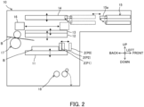
- the stage 11 is disposed so as to be movable up and down, and as illustrated in FIG. 2 , a bill B to be dispensed or a bill B to be deposited is stacked thereon.
- the bill B is an example of a paper sheet.
- the pusher 12 is disposed above the stage 11.
- the pusher 12 is disposed so as to be movable up and down, and can press the bill B on the stage 11 from above.
- the pusher plate 13 is disposed above the pusher 12.
- the pusher plate 13 is disposed so as to be movable up and down, and receives from the supply unit 17 the bill B to be returned out of the bills B fed from the stage 11 by the feeding unit 18.
- the roof 14 is disposed above the pusher plate 13.
- the roof 14 is disposed so as to be movable up and down.
- the shuttle 15 includes, for example, a pair of upper and lower conveyance belts capable of nipping the bill B, and moves in the front-back direction to a front position (see the solid line in FIG. 2 ) at the time of depositing and dispensing the bill B and a back position (see the dotted line in FIG. 2 ) at which the bill B is delivered to and from the stage 11.
- the shuttle 15 is provided at the back end thereof with a stopper 15a that prevents the bill B from falling to the backside from the inside of the shuttle 15.
- the stopper 15a rotates to a position where a space between the back ends of the paired upper and lower conveyance belts of the shuttle 15 is opened (see the solid line in FIG. 2 ) and a position where the space is closed (see the dotted line in FIG. 2 ).
- the push-in wall 16 is disposed to be movable in the front-back direction, and pushes the bill B on the stage 11 to the front side toward the shuttle 15 at the time of dispensing (moves from the solid-line position to the dotted-line position in FIG. 2 ).
- the supply unit 17 includes, for example, a fin roller and a roller.
- the supply unit 17 supplies the bill B to be dispensed toward the stage 11 or supplies the bill B to be returned toward the pusher plate 13.
- the feeding unit 18 includes, for example, a roller, a separator roller, and the like.
- the feeding unit 18 feeds the deposited bill B toward the identification unit 20 from the stage 11 that has moved further downward than the position illustrated in FIG. 2 (see the dotted arrow in FIG. 2 ).
- the drive gear 19 illustrated in FIG. 3 is rotated, for example, by power of a drive source of a not-illustrated conveyance mechanism that conveys the bill B in the bill depositing and dispensing unit 10.
- the conveyance mechanism is an example of a separate mechanism, which is different from the guide mechanism 1, and desirably includes a motor or the like capable of moving a drive target to three or more positions.
- the separate mechanism described above may be any mechanism capable of applying power to a power transmission mechanism 3, and is not limited to the conveyance mechanism.
- the identification unit 20 is disposed below the bill depositing and dispensing unit 10, and determines the authenticity, contamination, corner folding, and the like of the bill B conveyed from the bill depositing and dispensing unit 10 (the feeding unit 18).
- the temporarily reserving unit 30 temporarily stores the bill B that is conveyed from the bill depositing and dispensing unit 10 to the identification unit 20 and determined to be normal in the identification unit 20.
- the rejection unit 40 stores the bill B that is not to be returned, out of the bills B determined to be abnormal in the identification unit 20.
- the intermediate conveyance unit 50 conveys the bill B in the front-back direction between the identification unit 20 and the plurality of storage cassettes 60.
- the plurality of storage cassettes 60 store, for example, the bills B of different types from each other.
- the storage cassettes 60 can eject the stored bills B. Therefore, the bills B stored in the storage cassettes 60 are used for dispensing.
- FIG. 3 is a perspective view of the guide mechanism 1 as viewed from the upper left.
- FIG. 4 is a perspective view of the power transmission mechanism 3 and a switching drive unit 4 as viewed from the upper right.
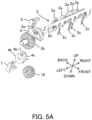
- FIGS. 5A and 5B are perspective views of the power transmission mechanism 3 (an intermittent gear 3a is omitted) and the switching drive unit 4 (a rotary solenoid 4a is omitted) as viewed from the upper left and the upper right, respectively.
- the guide mechanism 1 includes a guide 2, the power transmission mechanism 3, the switching drive unit 4, a rack 5, a guide detection sensor 6, and a gear detection sensor 7.
- the guide 2 includes a plurality of abutting members 2a, a connecting member 2b, and a plurality of entry prevention members 2c, and regulates the position of the stacked bill B.
- the guide 2 is movable to three or more positions, and the three or more positions preferably include, for example, two or more regulation positions P1 and P2 that regulate the position of the bill B above the stage 11 and a retraction position P0 that does not interfere with upward and downward movement of the stage 11 as illustrated in FIG. 2 .
- the regulation positions P1 and P2 are preferably different from each other in the position in the conveyance direction (the right-left direction in FIG.
- the guide 2 is preferably movable according to the size of the bill B so as to form a storage space (stacking space) for the bill B in the shorter direction (the conveyance direction) to be larger than the bill B by, for example, about 3 mm to 5 mm.
- the plurality of abutting members 2a are arranged to be spaced from each other in the longer direction (right-left direction) of the bill B.
- the bill B supplied to the stage 11 by the supply unit 17 illustrated in FIG. 2 abuts on the abutting members 2a.
- the connecting member 2b extends in the longer direction (right-left direction) orthogonal to the conveyance direction of the bill B and connects the plurality of abutting members 2a.
- the plurality of abutting members 2a are fixed to the connecting member 2b at the respective central portions thereof in the up-down direction by screwing.
- the plurality of entry prevention members 2c are fixed to the connecting member 2b at the upper ends of the entry prevention members 2c so as to hang down from the connecting member 2b.
- the entry prevention member 2c prevents the bill B from entering from below the connecting member 2b.
- the power transmission mechanism 3 includes the intermittent gear 3a and an idle gear 3b, and as will be described in detail below, moves the guide 2 to the three or more positions by means of power obtained from the drive gear 19 of the separate mechanism (for example, the conveyance mechanism including a conveyance roller that conveys the bill B), which is different from the guide mechanism 1.
- the separate mechanism for example, the conveyance mechanism including a conveyance roller that conveys the bill B
- the intermittent gear 3a includes a plurality of teeth 3a-1, a housing portion 3a-2, a back lid 3a-3 (see FIG. 4 ), and a detected piece 3a-4 (see FIG. 4 ), and rotates about the axis in the right-left direction.
- the intermittent gear 3a is provided with two areas in which the teeth 3a-1 are provided and two areas in which the teeth 3a-1 are not provided. That is, the intermittent gear 3a has the teeth 3a-1 only in some parts in the rotation direction. One of the two areas provided with the teeth 3a-1 meshes with the idle gear 3b, and the other meshes with the drive gear 19.
- the housing portion 3a-2 protrudes leftward from the intermittent gear 3a.
- the housing portion 3a-2 has a cylindrical shape having a shorter diameter than that of the region where the teeth 3a-1 are provided, and houses an actuating member 4b and a torsion spring 4c of the switching drive unit 4 to be described below illustrated in FIGS. 5A and 5B .
- the back lid 3a-3 has a circular plate shape and is provided at the right end of the intermittent gear 3a.
- the back lid 3a-3 is provided with a stopper hole 3a-3a extending in a fan shape from the rotation center of the intermittent gear 3a.
- a protrusion 4b-1 of the actuating member 4b described below is inserted.
- the detected piece 3a-4 extends so as to protrude in the radial direction of the intermittent gear 3a more than the teeth 3a-1 do.
- the detected piece 3a-4 is detected by the gear detection sensor 7 described below at a rotation angle at which the teeth 3a-1 of the intermittent gear 3a do not mesh with the drive gear 19.
- the idle gear 3b meshes with the intermittent gear 3a having a rotation angle of meshing with the drive gear 19.
- the idle gear 3b meshes with the rack 5 described below.
- the switching drive unit 4 includes the rotary solenoid 4a, and the actuating member 4b and the torsion spring 4c illustrated in FIGS. 5A and 5B .
- the rotary solenoid 4a is an example of a switching drive source.
- the rotary solenoid 4a switches the power transmission mechanism 3 to a transmission state (state in which power of the separate mechanism is transmitted to the guide 2) by rotating the intermittent gear 3a such that the teeth 3a-1 mesh with the drive gear 19, and switches the power transmission mechanism 3 to a non-transmission state (state in which power of the separate mechanism is not transmitted to the guide 2) by rotating the intermittent gear 3a such that the teeth 3a-1 do not mesh with the drive gear 19.
- the range in which the intermittent gear 3a is rotated by the rotary solenoid 4a may be, for example, about 20°.
- the actuating member 4b illustrated in FIGS. 5A and 5B has a not-illustrated drive shaft, having, for example, a D-shaped cross section, of the rotary solenoid 4a inserted from the left end illustrated in FIG. 5A , and rotates integrally with the drive shaft of the rotary solenoid 4a.
- the protrusion 4b-1 protruding rightward. As illustrated in FIG. 4 , the protrusion 4b-1 is inserted in the stopper hole 3a-3a of the back lid 3a-3 described above.
- the torsion spring 4c is wound around the actuating member 4b, one end thereof is hooked and fixed to the actuating member 4b as illustrated in FIG. 5B , and the other end thereof is hooked and fixed to the back lid 3a-3 of the intermittent gear 3a illustrated in FIG. 4 .
- the torsion spring 4c biases the actuating member 4b so as to rotate the back lid 3a-3 (intermittent gear 3a) clockwise in FIG. 4 .
- the end of the stopper hole 3a-3a of the back lid 3a-3 comes into contact with the protrusion 4b-1 of the actuating member 4b, and the rotation of the intermittent gear 3a is regulated.
- the biasing force of the torsion spring 4c is designed to be equal to or less than the holding force of the rotary solenoid 4a.
- the rack 5 illustrated in FIGS. 3 and 5A meshes with the idle gear 3b at the lower end, and moves in the front-back direction with the rotation of the idle gear 3b.
- the rack 5 is fixed to the guide 2 by screwing. Therefore, the guide 2 moves in the front-back direction integrally with the rack 5.
- a guide member such as a rack is preferably disposed at the right end of the guide 2 as well.
- a detected piece 5a is provided to protrude upward.
- the detected piece 5a is detected by the guide detection sensor 6 when the guide 2 is at the retraction position P0 illustrated in FIG. 2 .
- the guide detection sensor 6 is, for example, a light shielding sensor having a downward U shape, and detects the detected piece 5a when the detection light is shielded by the detected piece 5a.
- the gear detection sensor 7 is, for example, a light shielding sensor having an upward U shape, and detects the detected piece 3a-4 when the detection light is shielded by the detected piece 3a-4 of the intermittent gear 3a.
- the bill B conveyed in the shorter direction abuts on the guide 2, but the bill B conveyed in the longer direction may abut on the guide 2.
- the guide 2 is not limited to one on which the bill B abuts, and may be arranged on one side or both sides in a direction orthogonal to the conveyance direction of the bill B as long as the guide 2 regulates the position of the bill B (paper sheet).
- the power transmission mechanism 3 includes the intermittent gear 3a in the above description, the power transmission mechanism 3 is not limited to one including the intermittent gear 3a as long as the guide 2 is moved to three or more positions by power obtained from the separate mechanism (drive gear 19), which is different from the guide mechanism 1.
- the switching drive unit 4 includes the rotary solenoid 4a, but may include another drive source.
- this drive source moves the drive target to three or more positions
- the drive source can move the guide 2 to three or more positions by omitting the power transmission mechanism 3. Therefore, the drive source of the guide mechanism 1 may be a simple source that moves the drive target to only two positions.
- the configuration for moving the guide 2 is not limited to the configuration using the rack 5. In this manner, various configurations in the above description are illustrative only, and can appropriately be changed.
- the guide mechanism 1 arranged in the bill processing machine 100 is the guide mechanism 1 including the guide 2 that regulates the position of the bill B (an example of a paper sheet) stacked, and includes the power transmission mechanism 3 that moves the guide 2 to the retraction position P0 and the regulation positions P1 and P2 (an example of three or more positions) by means of power obtained from the drive gear 19 (separate mechanism), which is different from the guide mechanism 1, and the switching drive unit 4 that switches the power transmission mechanism 3 between a transmission state in which the power of the drive gear 19 is transmitted to the guide 2 and a non-transmission state in which the power of the drive gear 19 is not transmitted.
- the guide 2 can be moved to the plurality of regulation positions P1 and P2 and the like according to the size of the bill B stacked on the stage 11, so that a storage space corresponding to the size of the bill B can be formed.
- the power transmission mechanism 3 moves the guide 2 by means of the power obtained from the drive gear 19, the guide 2 can be moved to three or more positions with a simple configuration in which the guide mechanism 1 itself does not have a drive source for moving the guide 2 to three or more positions. Therefore, according to the present embodiment, the storage space corresponding to the size of the bill B can be formed with a simple configuration.
- the power transmission mechanism 3 includes the intermittent gear 3a having the teeth 3a-1 only in some parts in the rotation direction, and the switching drive unit 4 switches the power transmission mechanism 3 to the transmission state by rotating the intermittent gear 3a such that the teeth 3a-1 mesh with the drive gear 19 (separate mechanism), and switches the power transmission mechanism 3 to the non-transmission state by rotating the intermittent gear 3a such that the teeth 3a-1 do not mesh with the drive gear 19.
- the power transmission mechanism 3 can be switched between the transmission state and the non-transmission state with a simple configuration using the intermittent gear 3a.
- the guide 2 regulates the position of the bill B stacked on the stage 11 that is movable up and down
- the three or more positions to which the guide 2 is movable include the two or more regulation positions P1 and P2 that regulate the position of the bill B above the stage 11 and the retraction position P0 that does not interfere with upward and downward movement of the stage 11.
- the present invention is not limited to the above-mentioned embodiment as it is, and can be embodied by modifying the components thereof.
- various inventions can be formed by appropriately combining the plurality of components disclosed in the present embodiment. In this manner, various modifications and applications of the invention can be made without departing from the spirit of the invention.
Landscapes
- Engineering & Computer Science (AREA)
- Mechanical Engineering (AREA)
- Physics & Mathematics (AREA)
- General Physics & Mathematics (AREA)
- Pile Receivers (AREA)
Abstract
Description
- The present invention relates to a guide mechanism and a paper sheet handling apparatus.
- Conventionally, a guide mechanism including a guide that regulates a position of a paper sheet stacked in a bill storage unit of a cash deposit machine, an automated teller machine (ATM), or the like is used.
- For example, a bill processing apparatus including a movable guide member that regulates the length of a bill storage space in the longer direction of a bill and moves in the longer direction of the bill is known (See, for example,
JP 2021-067986 A - In addition, a sheet processing apparatus including a pair of alignment members that are provided to be movable in the sheet width direction intersecting with the sheet conveyance direction and align both ends of a sheet is known (See, for example,
JP 2006-306535 A - For example, in a guide that conveys a paper sheet in the conveyance direction parallel to the shorter direction of the paper sheet and regulates the position of the paper sheet at the back in the conveyance direction, it is desirable to form a storage space for the paper sheet in the shorter direction to be larger than the paper sheet by, for example, about 3 mm to 5 mm.
- Therefore, in a case where paper sheets of a plurality of sizes are stacked, the guide is moved in accordance with the size of each paper sheet in order to form an optimum storage space corresponding to each of the plurality of sizes of the paper sheets.
- However, for example, in a case where the guide is moved in two stages using a rotary solenoid, the guide can be moved only to the retraction position and one regulation position. In addition, in a case where a motor or the like capable of freely moving the guide is arranged, the cost is high.
- An object of the present invention is to provide a guide mechanism and a paper sheet handling apparatus capable of forming a storage space corresponding to a size of a paper sheet with a simple configuration.
- A guide mechanism disclosed herein is a guide mechanism including a guide that regulates a position of a paper sheet stacked, and includes a power transmission mechanism that moves the guide to three or more positions by means of power obtained from a separate mechanism, which is different from the guide mechanism, and a switching drive unit that switches the power transmission mechanism between a transmission state in which the power of the separate mechanism is transmitted to the guide and a non-transmission state in which the power of the separate mechanism is not transmitted.
- A paper sheet handling apparatus disclosed herein is a paper sheet handling apparatus including a guide mechanism, and the guide mechanism includes a guide that regulates a position of a paper sheet stacked, a power transmission mechanism that moves the guide to three or more positions by means of power obtained from a separate mechanism, which is different from the guide mechanism, and a switching drive unit that switches the power transmission mechanism between a transmission state in which the power of the separate mechanism is transmitted to the guide and a non-transmission state in which the power of the separate mechanism is not transmitted.
- According to the guide mechanism and the paper sheet handling apparatus of the disclosure, the storage space corresponding to the size of the paper sheet can be formed with a simple configuration.
-
-
FIG. 1 is a left side view illustrating an internal structure of a bill processing machine according to an embodiment; -
FIG. 2 is a left side view illustrating an internal structure of a bill depositing and dispensing unit according to the embodiment; -
FIG. 3 is a perspective view of a guide mechanism as viewed from the upper left according to the embodiment; -
FIG. 4 is a perspective view of a power transmission mechanism and a switching drive unit as viewed from the upper right according to the embodiment; -
FIG. 5A is a perspective view of the power transmission mechanism (an intermittent gear is omitted) and the switching drive unit (a rotary solenoid is omitted) as viewed from the upper left according to the embodiment; -
FIG. 5B is a perspective view of the power transmission mechanism and the like (the intermittent gear and the rotary solenoid are omitted) as viewed from the upper right according to the embodiment; and -
FIG. 6 is a perspective view for describing the operation of the power transmission mechanism according to the embodiment. - Hereinbelow, a guide mechanism and a paper sheet handling apparatus according to an embodiment of the present invention will be described with reference to the drawings using a
guide mechanism 1 and abill processing machine 100 as examples. -
FIG. 1 is a left side view illustrating an internal structure of thebill processing machine 100. - Note that the up-down, front-back, and right-left directions illustrated in
FIG. 1 andFIGS. 2 to 6 to be described below are illustrative only in a case where a customer side of thebill processing machine 100 is the front direction. For example, the up-down direction is a vertical direction, and the front-back direction and the right-left direction are horizontal directions. - The
bill processing machine 100 illustrated inFIG. 1 is, for example, an ATM, a bill recycle unit (BRU), a cash dispenser (CD), or a teller cash recycler (TCR), and includes a bill depositing anddispensing unit 10, anidentification unit 20, a temporarily reservingunit 30, arejection unit 40, anintermediate conveyance unit 50, and a plurality ofstorage cassettes 60. Note that thebill processing machine 100 is an example of a paper sheet handling apparatus. Since the paper sheet handling apparatus refers to any apparatus that performs some processing such as conveyance on a paper sheet, the paper sheet handling apparatus can be regarded as, for example, only the bill depositing and dispensingunit 10. - As illustrated in
FIG. 2 , the bill depositing and dispensingunit 10 includes a guide mechanism 1 (only aguide 2 is illustrated inFIG. 2 ) to be described below, astage 11, apusher 12, apusher plate 13, aroof 14, ashuttle 15, a push-inwall 16, asupply unit 17, afeeding unit 18, and a drive gear 19 (seeFIGS. 3 to 6 ). - The
stage 11 is disposed so as to be movable up and down, and as illustrated inFIG. 2 , a bill B to be dispensed or a bill B to be deposited is stacked thereon. Note that the bill B is an example of a paper sheet. - The
pusher 12 is disposed above thestage 11. Thepusher 12 is disposed so as to be movable up and down, and can press the bill B on thestage 11 from above. - The
pusher plate 13 is disposed above thepusher 12. Thepusher plate 13 is disposed so as to be movable up and down, and receives from thesupply unit 17 the bill B to be returned out of the bills B fed from thestage 11 by thefeeding unit 18. - The
roof 14 is disposed above thepusher plate 13. Theroof 14 is disposed so as to be movable up and down. - The
shuttle 15 includes, for example, a pair of upper and lower conveyance belts capable of nipping the bill B, and moves in the front-back direction to a front position (see the solid line inFIG. 2 ) at the time of depositing and dispensing the bill B and a back position (see the dotted line inFIG. 2 ) at which the bill B is delivered to and from thestage 11. Theshuttle 15 is provided at the back end thereof with astopper 15a that prevents the bill B from falling to the backside from the inside of theshuttle 15. Thestopper 15a rotates to a position where a space between the back ends of the paired upper and lower conveyance belts of theshuttle 15 is opened (see the solid line inFIG. 2 ) and a position where the space is closed (see the dotted line inFIG. 2 ). - The push-in
wall 16 is disposed to be movable in the front-back direction, and pushes the bill B on thestage 11 to the front side toward theshuttle 15 at the time of dispensing (moves from the solid-line position to the dotted-line position inFIG. 2 ). - The
supply unit 17 includes, for example, a fin roller and a roller. Thesupply unit 17 supplies the bill B to be dispensed toward thestage 11 or supplies the bill B to be returned toward thepusher plate 13. - The
feeding unit 18 includes, for example, a roller, a separator roller, and the like. Thefeeding unit 18 feeds the deposited bill B toward theidentification unit 20 from thestage 11 that has moved further downward than the position illustrated inFIG. 2 (see the dotted arrow inFIG. 2 ). - The
drive gear 19 illustrated inFIG. 3 is rotated, for example, by power of a drive source of a not-illustrated conveyance mechanism that conveys the bill B in the bill depositing and dispensingunit 10. The conveyance mechanism is an example of a separate mechanism, which is different from theguide mechanism 1, and desirably includes a motor or the like capable of moving a drive target to three or more positions. Note that the separate mechanism described above may be any mechanism capable of applying power to apower transmission mechanism 3, and is not limited to the conveyance mechanism. - Returning to
FIG. 1 , theidentification unit 20 is disposed below the bill depositing and dispensingunit 10, and determines the authenticity, contamination, corner folding, and the like of the bill B conveyed from the bill depositing and dispensing unit 10 (the feeding unit 18). - The temporarily reserving
unit 30 temporarily stores the bill B that is conveyed from the bill depositing and dispensingunit 10 to theidentification unit 20 and determined to be normal in theidentification unit 20. - The
rejection unit 40 stores the bill B that is not to be returned, out of the bills B determined to be abnormal in theidentification unit 20. - The
intermediate conveyance unit 50 conveys the bill B in the front-back direction between theidentification unit 20 and the plurality ofstorage cassettes 60. - The plurality of
storage cassettes 60 store, for example, the bills B of different types from each other. Thestorage cassettes 60 can eject the stored bills B. Therefore, the bills B stored in thestorage cassettes 60 are used for dispensing. -
FIG. 3 is a perspective view of theguide mechanism 1 as viewed from the upper left. -
FIG. 4 is a perspective view of thepower transmission mechanism 3 and aswitching drive unit 4 as viewed from the upper right. -
FIGS. 5A and5B are perspective views of the power transmission mechanism 3 (anintermittent gear 3a is omitted) and the switching drive unit 4 (arotary solenoid 4a is omitted) as viewed from the upper left and the upper right, respectively. - As illustrated in
FIG. 3 , theguide mechanism 1 includes aguide 2, thepower transmission mechanism 3, theswitching drive unit 4, arack 5, aguide detection sensor 6, and agear detection sensor 7. - The
guide 2 includes a plurality of abuttingmembers 2a, a connectingmember 2b, and a plurality ofentry prevention members 2c, and regulates the position of the stacked bill B. Theguide 2 is movable to three or more positions, and the three or more positions preferably include, for example, two or more regulation positions P1 and P2 that regulate the position of the bill B above thestage 11 and a retraction position P0 that does not interfere with upward and downward movement of thestage 11 as illustrated inFIG. 2 . Note that the regulation positions P1 and P2 are preferably different from each other in the position in the conveyance direction (the right-left direction inFIG. 2 ) that is the shorter direction of the bill B, and theguide 2 is preferably movable according to the size of the bill B so as to form a storage space (stacking space) for the bill B in the shorter direction (the conveyance direction) to be larger than the bill B by, for example, about 3 mm to 5 mm. - Returning to
FIG. 3 , the plurality of abuttingmembers 2a are arranged to be spaced from each other in the longer direction (right-left direction) of the bill B. For example, the bill B supplied to thestage 11 by thesupply unit 17 illustrated inFIG. 2 abuts on the abuttingmembers 2a. - The connecting
member 2b extends in the longer direction (right-left direction) orthogonal to the conveyance direction of the bill B and connects the plurality of abuttingmembers 2a. The plurality of abuttingmembers 2a are fixed to the connectingmember 2b at the respective central portions thereof in the up-down direction by screwing. - The plurality of
entry prevention members 2c are fixed to the connectingmember 2b at the upper ends of theentry prevention members 2c so as to hang down from the connectingmember 2b. Theentry prevention member 2c prevents the bill B from entering from below the connectingmember 2b. - The
power transmission mechanism 3 includes theintermittent gear 3a and anidle gear 3b, and as will be described in detail below, moves theguide 2 to the three or more positions by means of power obtained from thedrive gear 19 of the separate mechanism (for example, the conveyance mechanism including a conveyance roller that conveys the bill B), which is different from theguide mechanism 1. - The
intermittent gear 3a includes a plurality ofteeth 3a-1, ahousing portion 3a-2, aback lid 3a-3 (seeFIG. 4 ), and a detectedpiece 3a-4 (seeFIG. 4 ), and rotates about the axis in the right-left direction. - In the example of
FIG. 3 , theintermittent gear 3a is provided with two areas in which theteeth 3a-1 are provided and two areas in which theteeth 3a-1 are not provided. That is, theintermittent gear 3a has theteeth 3a-1 only in some parts in the rotation direction. One of the two areas provided with theteeth 3a-1 meshes with theidle gear 3b, and the other meshes with thedrive gear 19. - The
housing portion 3a-2 protrudes leftward from theintermittent gear 3a. In addition, thehousing portion 3a-2 has a cylindrical shape having a shorter diameter than that of the region where theteeth 3a-1 are provided, and houses an actuatingmember 4b and atorsion spring 4c of the switchingdrive unit 4 to be described below illustrated inFIGS. 5A and5B . - As illustrated in
FIG. 4 , theback lid 3a-3 has a circular plate shape and is provided at the right end of theintermittent gear 3a. Theback lid 3a-3 is provided with astopper hole 3a-3a extending in a fan shape from the rotation center of theintermittent gear 3a. In thestopper hole 3a-3a, aprotrusion 4b-1 of the actuatingmember 4b described below is inserted. - The detected
piece 3a-4 extends so as to protrude in the radial direction of theintermittent gear 3a more than theteeth 3a-1 do. In addition, the detectedpiece 3a-4 is detected by thegear detection sensor 7 described below at a rotation angle at which theteeth 3a-1 of theintermittent gear 3a do not mesh with thedrive gear 19. - The
idle gear 3b meshes with theintermittent gear 3a having a rotation angle of meshing with thedrive gear 19. In addition, as illustrated inFIG. 3 , theidle gear 3b meshes with therack 5 described below. - The switching
drive unit 4 includes therotary solenoid 4a, and the actuatingmember 4b and thetorsion spring 4c illustrated inFIGS. 5A and5B . - The
rotary solenoid 4a is an example of a switching drive source. Therotary solenoid 4a switches thepower transmission mechanism 3 to a transmission state (state in which power of the separate mechanism is transmitted to the guide 2) by rotating theintermittent gear 3a such that theteeth 3a-1 mesh with thedrive gear 19, and switches thepower transmission mechanism 3 to a non-transmission state (state in which power of the separate mechanism is not transmitted to the guide 2) by rotating theintermittent gear 3a such that theteeth 3a-1 do not mesh with thedrive gear 19. Note that the range in which theintermittent gear 3a is rotated by therotary solenoid 4a may be, for example, about 20°. - The actuating
member 4b illustrated inFIGS. 5A and5B has a not-illustrated drive shaft, having, for example, a D-shaped cross section, of therotary solenoid 4a inserted from the left end illustrated inFIG. 5A , and rotates integrally with the drive shaft of therotary solenoid 4a. - As illustrated in
FIG. 5B , at the right end of the actuatingmember 4b is provided theprotrusion 4b-1 protruding rightward. As illustrated inFIG. 4 , theprotrusion 4b-1 is inserted in thestopper hole 3a-3a of theback lid 3a-3 described above. - The
torsion spring 4c is wound around the actuatingmember 4b, one end thereof is hooked and fixed to the actuatingmember 4b as illustrated inFIG. 5B , and the other end thereof is hooked and fixed to theback lid 3a-3 of theintermittent gear 3a illustrated inFIG. 4 . Thetorsion spring 4c biases the actuatingmember 4b so as to rotate theback lid 3a-3 (intermittent gear 3a) clockwise inFIG. 4 . As a result, the end of thestopper hole 3a-3a of theback lid 3a-3 comes into contact with theprotrusion 4b-1 of the actuatingmember 4b, and the rotation of theintermittent gear 3a is regulated. In this state, when therotary solenoid 4a rotates the actuatingmember 4b counterclockwise inFIG. 4 (clockwise inFIG. 6 ), theintermittent gear 3a rotates counterclockwise inFIG. 4 (clockwise inFIG. 6 ) against the biasing force of thetorsion spring 4c, and theteeth 3a-1 mesh with theidle gear 3b and thedrive gear 19. As a result, the power of thedrive gear 19 is transmitted to theguide 2 via theintermittent gear 3a, theidle gear 3b, and therack 5 described below. Thereafter, when therotary solenoid 4a rotates the actuatingmember 4b clockwise inFIG. 4 (counterclockwise inFIG. 6 ), theintermittent gear 3a also rotates clockwise (counterclockwise inFIG. 6 ) by the biasing force of thetorsion spring 4c, and theteeth 3a-1 do not mesh with theidle gear 3b and thedrive gear 19. The biasing force of thetorsion spring 4c is designed to be equal to or less than the holding force of therotary solenoid 4a. - The
rack 5 illustrated inFIGS. 3 and5A meshes with theidle gear 3b at the lower end, and moves in the front-back direction with the rotation of theidle gear 3b. Therack 5 is fixed to theguide 2 by screwing. Therefore, theguide 2 moves in the front-back direction integrally with therack 5. Although therack 5 is fixed to the left end of theguide 2, a guide member such as a rack is preferably disposed at the right end of theguide 2 as well. - At the upper end of the
rack 5, a detectedpiece 5a is provided to protrude upward. The detectedpiece 5a is detected by theguide detection sensor 6 when theguide 2 is at the retraction position P0 illustrated inFIG. 2 . - The
guide detection sensor 6 is, for example, a light shielding sensor having a downward U shape, and detects the detectedpiece 5a when the detection light is shielded by the detectedpiece 5a. - As illustrated in
FIGS. 4 to 5B , thegear detection sensor 7 is, for example, a light shielding sensor having an upward U shape, and detects the detectedpiece 3a-4 when the detection light is shielded by the detectedpiece 3a-4 of theintermittent gear 3a. - Note that, in the above description, the bill B conveyed in the shorter direction abuts on the
guide 2, but the bill B conveyed in the longer direction may abut on theguide 2. In addition, theguide 2 is not limited to one on which the bill B abuts, and may be arranged on one side or both sides in a direction orthogonal to the conveyance direction of the bill B as long as theguide 2 regulates the position of the bill B (paper sheet). - Although the
power transmission mechanism 3 includes theintermittent gear 3a in the above description, thepower transmission mechanism 3 is not limited to one including theintermittent gear 3a as long as theguide 2 is moved to three or more positions by power obtained from the separate mechanism (drive gear 19), which is different from theguide mechanism 1. - In the above description, the switching
drive unit 4 includes therotary solenoid 4a, but may include another drive source. However, in a case where this drive source moves the drive target to three or more positions, the drive source can move theguide 2 to three or more positions by omitting thepower transmission mechanism 3. Therefore, the drive source of theguide mechanism 1 may be a simple source that moves the drive target to only two positions. - Although the
power transmission mechanism 3 moves theguide 2 via therack 5 in the above description, the configuration for moving theguide 2 is not limited to the configuration using therack 5. In this manner, various configurations in the above description are illustrative only, and can appropriately be changed. - In the present embodiment described above, for example, the
guide mechanism 1 arranged in the bill processing machine 100 (an example of a paper sheet handling apparatus) is theguide mechanism 1 including theguide 2 that regulates the position of the bill B (an example of a paper sheet) stacked, and includes thepower transmission mechanism 3 that moves theguide 2 to the retraction position P0 and the regulation positions P1 and P2 (an example of three or more positions) by means of power obtained from the drive gear 19 (separate mechanism), which is different from theguide mechanism 1, and the switchingdrive unit 4 that switches thepower transmission mechanism 3 between a transmission state in which the power of thedrive gear 19 is transmitted to theguide 2 and a non-transmission state in which the power of thedrive gear 19 is not transmitted. - As a result, for example, the
guide 2 can be moved to the plurality of regulation positions P1 and P2 and the like according to the size of the bill B stacked on thestage 11, so that a storage space corresponding to the size of the bill B can be formed. In addition, since thepower transmission mechanism 3 moves theguide 2 by means of the power obtained from thedrive gear 19, theguide 2 can be moved to three or more positions with a simple configuration in which theguide mechanism 1 itself does not have a drive source for moving theguide 2 to three or more positions. Therefore, according to the present embodiment, the storage space corresponding to the size of the bill B can be formed with a simple configuration. - In addition, in the present embodiment, the
power transmission mechanism 3 includes theintermittent gear 3a having theteeth 3a-1 only in some parts in the rotation direction, and the switchingdrive unit 4 switches thepower transmission mechanism 3 to the transmission state by rotating theintermittent gear 3a such that theteeth 3a-1 mesh with the drive gear 19 (separate mechanism), and switches thepower transmission mechanism 3 to the non-transmission state by rotating theintermittent gear 3a such that theteeth 3a-1 do not mesh with thedrive gear 19. - Thus, the
power transmission mechanism 3 can be switched between the transmission state and the non-transmission state with a simple configuration using theintermittent gear 3a. - In addition, in the present embodiment, the
guide 2 regulates the position of the bill B stacked on thestage 11 that is movable up and down, and the three or more positions to which theguide 2 is movable include the two or more regulation positions P1 and P2 that regulate the position of the bill B above thestage 11 and the retraction position P0 that does not interfere with upward and downward movement of thestage 11. - As a result, it is possible to form a storage space corresponding to the size of the bill B by moving the
guide 2 to the plurality of regulation positions P1 and P2, and it is also possible to regulate the position of the bill B stacked on thestage 11 that is movable up and down by moving theguide 2 to the retraction position P0 that does not interfere with upward and downward movement of thestage 11. - Note that the present invention is not limited to the above-mentioned embodiment as it is, and can be embodied by modifying the components thereof. For example, various inventions can be formed by appropriately combining the plurality of components disclosed in the present embodiment. In this manner, various modifications and applications of the invention can be made without departing from the spirit of the invention.
Claims (4)
- A guide mechanism including a guide that regulates a position of a paper sheet stacked, the guide mechanism comprising:a power transmission mechanism that moves the guide to three or more positions by means of power obtained from a separate mechanism, which is different from the guide mechanism; anda switching drive unit that switches the power transmission mechanism between a transmission state in which the power of the separate mechanism is transmitted to the guide and a non-transmission state in which the power of the separate mechanism is not transmitted.
- The guide mechanism according to claim 1,wherein the power transmission mechanism includes an intermittent gear having teeth only in a part of a rotation direction, andwherein the switching drive unit switches the power transmission mechanism to the transmission state by rotating the intermittent gear such that the teeth mesh with the separate mechanism, and switches the power transmission mechanism to the non-transmission state by rotating the intermittent gear such that the teeth do not mesh with the separate mechanism.
- The guide mechanism according to claim 1 or 2,wherein the guide regulates the position of the paper sheet stacked on a stage that is movable up and down, andwherein the three or more positions of the guide include two or more regulation positions that regulate the position of the paper sheet above the stage and a retraction position that does not interfere with upward and downward movement of the stage.
- A paper sheet handling apparatus comprising a guide mechanism, wherein the guide mechanism includesa guide that regulates a position of a paper sheet stacked,a power transmission mechanism that moves the guide to three or more positions by means of power obtained from a separate mechanism, which is different from the guide mechanism, anda switching drive unit that switches the power transmission mechanism between a transmission state in which the power of the separate mechanism is transmitted to the guide and a non-transmission state in which the power of the separate mechanism is not transmitted.
Applications Claiming Priority (1)
| Application Number | Priority Date | Filing Date | Title |
|---|---|---|---|
| PCT/JP2021/047612 WO2023119492A1 (en) | 2021-12-22 | 2021-12-22 | Guide mechanism and paper-sheet handling device |
Publications (2)
| Publication Number | Publication Date |
|---|---|
| EP4456022A1 true EP4456022A1 (en) | 2024-10-30 |
| EP4456022A4 EP4456022A4 (en) | 2025-02-19 |
Family
ID=86901633
Family Applications (1)
| Application Number | Title | Priority Date | Filing Date |
|---|---|---|---|
| EP21968929.6A Pending EP4456022A4 (en) | 2021-12-22 | 2021-12-22 | GUIDE MECHANISM AND PAPER SHEET HANDLING DEVICE |
Country Status (5)
| Country | Link |
|---|---|
| US (1) | US12589968B2 (en) |
| EP (1) | EP4456022A4 (en) |
| JP (1) | JP7646875B2 (en) |
| CN (1) | CN118401974A (en) |
| WO (1) | WO2023119492A1 (en) |
Family Cites Families (7)
| Publication number | Priority date | Publication date | Assignee | Title |
|---|---|---|---|---|
| JPH02310250A (en) * | 1989-05-26 | 1990-12-26 | Ricoh Co Ltd | Paper loading device |
| JP3749131B2 (en) | 2001-02-19 | 2006-02-22 | ニスカ株式会社 | Sheet ejector |
| JP2006306535A (en) | 2005-04-26 | 2006-11-09 | Canon Inc | Sheet processing apparatus and image forming apparatus |
| JP2006327714A (en) * | 2005-05-23 | 2006-12-07 | Fujifilm Holdings Corp | Sheet stacking device, sheet stacking method and sheet loading device |
| JP4838671B2 (en) * | 2006-09-07 | 2011-12-14 | キヤノン株式会社 | Sheet conveying apparatus, sheet stacking apparatus, and image forming apparatus |
| JP6319764B2 (en) * | 2014-06-20 | 2018-05-09 | 株式会社Isowa | Sheet stacking apparatus and sheet stacking method |
| JP2021067986A (en) | 2019-10-18 | 2021-04-30 | オムロン株式会社 | Banknote processor and banknote storage cassette |
-
2021
- 2021-12-22 CN CN202180104881.XA patent/CN118401974A/en active Pending
- 2021-12-22 WO PCT/JP2021/047612 patent/WO2023119492A1/en not_active Ceased
- 2021-12-22 JP JP2023568884A patent/JP7646875B2/en active Active
- 2021-12-22 EP EP21968929.6A patent/EP4456022A4/en active Pending
-
2024
- 2024-05-28 US US18/675,911 patent/US12589968B2/en active Active
Also Published As
| Publication number | Publication date |
|---|---|
| US12589968B2 (en) | 2026-03-31 |
| US20240312282A1 (en) | 2024-09-19 |
| JPWO2023119492A1 (en) | 2023-06-29 |
| EP4456022A4 (en) | 2025-02-19 |
| JP7646875B2 (en) | 2025-03-17 |
| WO2023119492A1 (en) | 2023-06-29 |
| CN118401974A (en) | 2024-07-26 |
Similar Documents
| Publication | Publication Date | Title |
|---|---|---|
| US7942401B2 (en) | ATM equipped with structure for preventing rotation of stack roller | |
| EP2600322B1 (en) | Medium storage box | |
| US20030047601A1 (en) | Banknote receipt and pay-out apparatus | |
| EP3045413B1 (en) | Paper sheets stacking and feeding device | |
| KR20080052393A (en) | Paper sheet repetition mechanism | |
| CA3070064C (en) | Friction transport device and paper sheet transport device | |
| CN101884055B (en) | Apparatus for accepting and dispensing bank notes | |
| US20020096821A1 (en) | Apparatus handling paper sheets and the like | |
| WO2005088566A1 (en) | Device for handling paper sheets or the like, automatic transaction device, and device for conveying paper sheets or the like | |
| JP5969264B2 (en) | Banknote recirculation device | |
| EP3567560B1 (en) | Value note cassette | |
| US12589968B2 (en) | Guide mechanism and paper sheet handling apparatus | |
| JP6227397B2 (en) | Banknote handling equipment | |
| KR101375412B1 (en) | Paper sheet handling apparatus | |
| JP2001240294A (en) | Paper sheet stacking device, paper sheet storage, and paper sheet handling device | |
| CN107845185B (en) | Device for outputting notes of value with adjustable guide elements | |
| JP2009093279A (en) | Banknote handling equipment | |
| US12037217B2 (en) | Paper sheet stacking device and method for controlling paper sheet stacking device | |
| JP2025181239A (en) | Banknote handling equipment | |
| JP2023071481A (en) | Banknote handling device | |
| WO2025197053A1 (en) | Foreign matter removal device | |
| JP4571813B2 (en) | Construction method of paper sheet handling equipment | |
| JP2018032267A (en) | Medium storage and automatic transaction device | |
| JP2018112943A (en) | Paper sheet accumulation device and paper sheet processing apparatus | |
| JP2025059422A (en) | Paper handling equipment |
Legal Events
| Date | Code | Title | Description |
|---|---|---|---|
| STAA | Information on the status of an ep patent application or granted ep patent |
Free format text: STATUS: THE INTERNATIONAL PUBLICATION HAS BEEN MADE |
|
| PUAI | Public reference made under article 153(3) epc to a published international application that has entered the european phase |
Free format text: ORIGINAL CODE: 0009012 |
|
| STAA | Information on the status of an ep patent application or granted ep patent |
Free format text: STATUS: REQUEST FOR EXAMINATION WAS MADE |
|
| 17P | Request for examination filed |
Effective date: 20240521 |
|
| AK | Designated contracting states |
Kind code of ref document: A1 Designated state(s): AL AT BE BG CH CY CZ DE DK EE ES FI FR GB GR HR HU IE IS IT LI LT LU LV MC MK MT NL NO PL PT RO RS SE SI SK SM TR |
|
| REG | Reference to a national code |
Ref country code: DE Ref legal event code: R079 Free format text: PREVIOUS MAIN CLASS: G07D0011130000 Ipc: B65H0031200000 |
|
| A4 | Supplementary search report drawn up and despatched |
Effective date: 20250121 |
|
| RIC1 | Information provided on ipc code assigned before grant |
Ipc: G07D 11/17 20190101ALI20250115BHEP Ipc: B65H 31/24 20060101ALI20250115BHEP Ipc: B65H 83/02 20060101ALI20250115BHEP Ipc: B65H 31/02 20060101ALI20250115BHEP Ipc: B65H 31/20 20060101AFI20250115BHEP |
|
| DAV | Request for validation of the european patent (deleted) | ||
| DAX | Request for extension of the european patent (deleted) |