EP4455985A1 - Pseudo blood vessel pattern generation device and pseudo blood vessel pattern generation method - Google Patents
Pseudo blood vessel pattern generation device and pseudo blood vessel pattern generation method Download PDFInfo
- Publication number
- EP4455985A1 EP4455985A1 EP21969084.9A EP21969084A EP4455985A1 EP 4455985 A1 EP4455985 A1 EP 4455985A1 EP 21969084 A EP21969084 A EP 21969084A EP 4455985 A1 EP4455985 A1 EP 4455985A1
- Authority
- EP
- European Patent Office
- Prior art keywords
- image
- pseudo
- vascular pattern
- pseudo vascular
- processor
- Prior art date
- Legal status (The legal status is an assumption and is not a legal conclusion. Google has not performed a legal analysis and makes no representation as to the accuracy of the status listed.)
- Pending
Links
Images





Classifications
-
- G—PHYSICS
- G06—COMPUTING OR CALCULATING; COUNTING
- G06T—IMAGE DATA PROCESSING OR GENERATION, IN GENERAL
- G06T11/00—Two-dimensional [2D] image generation
-
- G—PHYSICS
- G06—COMPUTING OR CALCULATING; COUNTING
- G06T—IMAGE DATA PROCESSING OR GENERATION, IN GENERAL
- G06T1/00—General purpose image data processing
-
- G—PHYSICS
- G06—COMPUTING OR CALCULATING; COUNTING
- G06T—IMAGE DATA PROCESSING OR GENERATION, IN GENERAL
- G06T11/00—Two-dimensional [2D] image generation
- G06T11/10—Texturing; Colouring; Generation of textures or colours
-
- G—PHYSICS
- G06—COMPUTING OR CALCULATING; COUNTING
- G06T—IMAGE DATA PROCESSING OR GENERATION, IN GENERAL
- G06T3/00—Geometric image transformations in the plane of the image
-
- G—PHYSICS
- G06—COMPUTING OR CALCULATING; COUNTING
- G06T—IMAGE DATA PROCESSING OR GENERATION, IN GENERAL
- G06T5/00—Image enhancement or restoration
- G06T5/20—Image enhancement or restoration using local operators
-
- G—PHYSICS
- G06—COMPUTING OR CALCULATING; COUNTING
- G06V—IMAGE OR VIDEO RECOGNITION OR UNDERSTANDING
- G06V10/00—Arrangements for image or video recognition or understanding
- G06V10/70—Arrangements for image or video recognition or understanding using pattern recognition or machine learning
- G06V10/77—Processing image or video features in feature spaces; using data integration or data reduction, e.g. principal component analysis [PCA] or independent component analysis [ICA] or self-organising maps [SOM]; Blind source separation
- G06V10/776—Validation; Performance evaluation
-
- G—PHYSICS
- G06—COMPUTING OR CALCULATING; COUNTING
- G06V—IMAGE OR VIDEO RECOGNITION OR UNDERSTANDING
- G06V40/00—Recognition of biometric, human-related or animal-related patterns in image or video data
- G06V40/10—Human or animal bodies, e.g. vehicle occupants or pedestrians; Body parts, e.g. hands
- G06V40/14—Vascular patterns
Definitions
- the present disclosure relates to a pseudo vascular pattern generation device and a method of generating a pseudo vascular pattern.
- a large amount of data on vascular patterns is needed for developments of a biometric authentication algorithm and a biometric authentication system based on vascular patterns.
- Conventionally, developments of the biometric authentication algorithm and the biometric authentication system have been carried out by using vascular patterns (hereinafter, sometimes referred to as "actual vascular patterns") extracted from an image in which an actual living body has been captured (hereinafter, sometimes referred to as a “captured image”) has been carried out.
- actual vascular patterns extracted from an image in which an actual living body has been captured
- the actual vascular patterns extracted from the captured image correspond to data capable of identifying an individual, so that it is difficult to store the actual vascular patterns in a storage in terms of a contract with the subject to be imaged and a legal system adopted in each country. Accordingly, pseudo vascular patterns to be substituted for the actual vascular patterns are needed.
- Non Patent Literature 1 M. Sato, "Getting Started in Mathematical Life Sciences", ISBN: 4339067628, pp. 176 - 193, Corona corporation, 2020. (Date of issue: January 8, 2021 )
- the shape of the pseudo vascular patterns generated on the basis of the mathematical model is far from the shape of the actual vascular patterns. Furthermore, it is hard to generate patterns that are rich in diversity in the case where a pseudo vascular pattern is generated on the basis of the mathematical model, so that it is not realistic to use the pseudo vascular patterns that have been generated on the basis of the mathematical model in order to evaluate the biometric authentication algorithm.
- a pseudo vascular pattern generation device includes a processor.
- the processor generates a first image in which white noise has been added to a gray image, generates a second image in which the white noise included in the first image has been diffused, generates a third image in which a blood vessel enhancement filter has been applied to the second image, generates a fourth image in which a region of interest has been set to the third image, and generates a fifth image including a pseudo vascular pattern based on the fourth image.
- FIG. 1 is a diagram illustrating an example of a configuration of a pseudo vascular pattern generation system according to the present disclosure.
- the pseudo vascular pattern generation system 1 includes a pseudo vascular pattern generation device 10, an input device 20, and a display 30.
- the input device 20 and the display 30 are connected to the pseudo vascular pattern generation device 10.
- Examples of the input device 20 include, as one example, a pointing device, such as a mouse, and a keyboard.
- An example of the display 30 includes, as one example, a liquid crystal display (LCD) .
- LCD liquid crystal display
- the pseudo vascular pattern generation device 10 includes a processor 11 and a storage unit 12.
- the processor 11 include, as one example, a central processing unit (CPU), a digital signal processor (DSP), a field programmable gate array (FPGA), an application specific integrated circuit (ASIC), or the like.
- the storage unit 12 includes, as one example, a memory, a storage, or the like.
- the pseudo vascular pattern generation device 10 is implemented by, for example, a computer.
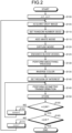
- FIG. 2 is a diagram illustrating one example of the flow of the process performed in the pseudo vascular pattern generation device according to the present disclosure.
- FIG. 3 to FIG. 11 are diagrams each illustrating one example of an image or images obtained in a course of a process of generating the pseudo vascular patterns according to the present disclosure.
- Step S100 the processor 11 initializes a value of a first counter n and a value of a second counter m to "1".
- the processor 11 acquires a gray image Ia ( FIG. 3 ) that is stored in the storage unit 12 in advance from the storage unit 12.
- a gradation value of each of the pixels that constitute an image takes one of values of 0 to 255
- an image in which, for example, the gradation values of all of the pixels are intermediate value of 128 that is located at a point between 0 and 255 is stored in advance as the gray image Ia in the storage unit 12.
- Step S110 the processor 11 sets a random number seed.
- Step S115 the processor 11 adds white noise under the same random number seed to all of the pixels included in the gray image Ia.
- an image Ib in which the white noise has been added to the gray image Ia (hereinafter, sometimes referred to as a "white noise added image") is generated ( FIG. 4 ).
- the processor 11 diffuses the white noise included in the white noise added image Ib.
- the processor 11 generates, by applying, for example, a Gaussian filter to the white noise added image Ib, an image Ic in which the white noise has been diffused in the white noise added image Ib (hereinafter, sometimes referred to as a "white noise diffusion image") ( FIG. 5 ).
- the processor 11 enhances blood vessels included in the white noise diffusion image Ic.
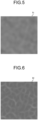
- the processor 11 generates, by applying, for example, a blood vessel enhancement filter, such as a Frangi filter, to the white noise diffusion image Ic, an image Id in which the blood vessel has been enhanced in the white noise diffusion image Ic (hereinafter, sometimes referred to as a "vascular enhancement image") ( FIG. 6 ).
- a blood vessel enhancement filter such as a Frangi filter
- the processor 11 performs a smoothing process on the vascular enhancement image Id.
- the processor 11 generates, by performing the smoothing process on the vascular enhancement image Id by using, for example, the Gaussian filter, an image Ie in which the smoothing process has been performed on the vascular enhancement image Id (hereinafter, sometimes referred to as a "smoothed image") ( FIG. 7 ). Moreover, it is possible to omit the process performed at Step S130.
- Step S135 the processor 11 inverse the color of the smoothed image Ie.
- an image If in which the smoothed image Ie has been subjected to negative-positive inversion (hereinafter, sometimes referred to as a "color inversion image") is generated ( FIG. 8 ).
- the processor 11 generates the color inversion image If by inversing the color of the vascular enhancement image Id.
- Step S140 the processor 11 sets a region of interest (ROI) to the color inversion image If.
- ROI region of interest
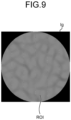
- an image Ig in which the region of interest has been set with respect to the color inversion image If (hereinafter, sometimes referred to as a "region of interest set image") is generated ( FIG. 9 ).
- the processor 11 sets the region of interest to the smoothed image Ie.
- the processor 11 sets the region of interest to the vascular enhancement image Id.
- the processor 11 After that, at Step S145, the processor 11 generates, by performing geometric transformation on the region of interest set image Ig, an image BVnm that includes a pseudo vascular pattern (hereinafter, sometimes referred to as a "pseudo vascular pattern image").
- an image BVnm that includes a pseudo vascular pattern (hereinafter, sometimes referred to as a "pseudo vascular pattern image").
- Example of the geometric transformation include, as one example, affine transformation, thin plate spline transformation, and the like.
- Step S150 the processor 11 causes the storage unit 12 to store the pseudo vascular pattern image BVnm that has been generated at Step S145.
- Step S155 the processor 11 determines whether or not the value of the second counter m reaches a second predetermined value M. If the second counter m does not reach the second predetermined value M (No at Step S155), the process proceeds to Step S160, whereas, if the second counter m reaches the second predetermined value M (Yes at Step S155), the process proceeds to Step S165.
- Step S160 the processor 11 increments the value of the second counter m. After the process at Step S160 has been performed, the process returns to Step S145.
- the processor 11 changes, in accordance with the value of the second counter m, a value of a parameter P that is used for geometric transformation performed at Step S145.
- the processor 11 sets the value of the parameter P to "Pa”
- the processor 11 sets the value of the parameter P to "Pb” that is different from Pa
- the processor 11 sets the value of the parameter P to "Pc” that is different from Pa and Pb.
- a first pseudo vascular pattern image BV11 is generated as a result of the region of interest set image Ig being subjected to geometric transformation by using the parameter Pa; in the case where the value of the second counter m is "2", a second pseudo vascular pattern image BV12 is generated as a result of region of interest set image Ig being subjected to geometric transformation by using the parameter Pb; and, in the case where the value of the second counter m is "3", a third pseudo vascular pattern image BV13 is generated as a result of region of interest set image Ig being subjected to geometric transformation by using the parameter Pc.
- Step S165 the processor 11 determines whether or not the value of the first counter n reaches a first predetermined value N. In the case where the value of the first counter n does not reach the first predetermined value N (No at Step S165), the process proceeds to Step S170, whereas, in the case where the value of the first counter n reaches the first predetermined value N (Yes at Step S165), the process ends.
- Step S170 the processor 11 increments the value of the first counter n. After the process at Step S170 has been performed, the process returns to Step S105.
- the processor 11 changes, in accordance with the value of the first counter n, the value of the random number seed that is to be set at Step S110.
- the processor 11 sets the value of the random number seed to "Sa”; in the case where, for example, the value of the first counter n is "2", the processor 11 sets the value of the random number seed to "Sb” that is different from Sa; in the case where, for example, the value of the first counter n is "3", the processor 11 sets the value of the random number seed to "Sc" that is different from Sa and Sb.
- the first predetermined value N is set to "3", as illustrated in FIG. 11 , under the condition that the value of the first counter n is "1", in the case where the value of the second counter m is "1", the first pseudo vascular pattern image BV11 based on the random number seed Sa and the parameter Pa is generated; in the case where the value of the second counter m is "2", the second pseudo vascular pattern image BV12 based on the random number seed Sa and the parameter Pb is generated; and in the case where the value of the second counter m is "3", the third pseudo vascular pattern image BV13 based on the random number seed Sa and the parameter Pc is generated. Furthermore, as illustrated in FIG.
- the first pseudo vascular pattern image BV11, the second pseudo vascular pattern image BV12, and the third pseudo vascular pattern image BV13 are generated on the basis of the parameters Pa, Pb, Pc that are different from each other under the condition of the same random number seed Sa.
- the feature points of the pseudo vascular pattern included in each of the first pseudo vascular pattern image BV11, the second pseudo vascular pattern image BV12, and the third pseudo vascular pattern image BV13 are similar with each other.
- the fourth pseudo vascular pattern image BV21, the fifth pseudo vascular pattern image BV22, and the sixth pseudo vascular pattern image BV23 are generated on the basis of the parameters Pa, Pb, and Pc that are different from each other under the same random number seed Sb.
- the feature points of the pseudo vascular pattern included in each of the fourth pseudo vascular pattern image BV21, the fifth pseudo vascular pattern image BV22, and the sixth pseudo vascular pattern image BV23 are similar with each other.
- the seventh pseudo vascular pattern image BV31, the eighth pseudo vascular pattern image BV32, and the ninth pseudo vascular pattern image BV33 are generated on the basis of the parameters Pa, Pb ,Pc that are different from each other under the same random number seed Sc.
- the feature points of the pseudo vascular pattern included in each of the seventh pseudo vascular pattern image BV31, the eighth pseudo vascular pattern image BV32, and the ninth pseudo vascular pattern image BV33 are similar with each other.
- the first pseudo vascular pattern image BV11, the second pseudo vascular pattern image BV12, and the third pseudo vascular pattern image BV13 are generated on the basis of the random number seed Sa;
- the fourth pseudo vascular pattern image BV21, the fifth pseudo vascular pattern image BV22, and the sixth pseudo vascular pattern image BV23 are generated on the basis of the random number seed Sb;
- the seventh pseudo vascular pattern image BV31, the eighth pseudo vascular pattern image BV32, and the ninth pseudo vascular pattern image BV33 are generated on the basis of the random number seed Sc.
- the feature points of the pseudo vascular pattern that are included in each of the first pseudo vascular pattern image BV11, the second pseudo vascular pattern image BV12, and the third pseudo vascular pattern image BV13, the feature points of the pseudo vascular pattern that are included in each of the fourth pseudo vascular pattern image BV21, the fifth pseudo vascular pattern image BV22, and the sixth pseudo vascular pattern image BV23, and the feature points of the pseudo vascular pattern included in each of the seventh pseudo vascular pattern image BV31, the eighth pseudo vascular pattern image BV32, and the ninth pseudo vascular pattern image BV33 are different from each other.
- the pseudo vascular pattern that is included in each of the first pseudo vascular pattern image BV11, the second pseudo vascular pattern image BV12, and the third pseudo vascular pattern image BV13 as three types of variations in the pseudo vascular pattern of a first person. Furthermore, it is possible to define the pseudo vascular pattern that is included in each of the fourth pseudo vascular pattern image BV21, the fifth pseudo vascular pattern image BV22, and the sixth pseudo vascular pattern image BV23 as three types of variations in the pseudo vascular pattern of the second person who is different from the first person.
- pseudo vascular pattern that is included in each of the seventh pseudo vascular pattern image BV31, the eighth pseudo vascular pattern image BV32, and the ninth pseudo vascular pattern image BV33 as three types of variations in the pseudo vascular pattern of the third person who is different from the first person and the second person.
- an operator is able to set the first predetermined value N and the second predetermined value M by using the input device 20. Furthermore, the operator is able to visually recognize the pseudo vascular pattern image BVnm by using the display 30.
- FIG. 12 is a diagram illustrating the measurement results of the FAR and the FRR with respect to the pseudo vascular pattern that has been generated by the pseudo vascular pattern generation device according to the present disclosure.
- FIG. 12 indicates the measurement results of l33 forms obtained in the case where 1,000,000 pseudo vascular pattern images are generated by the pseudo vascular pattern generation device 10 by setting the first predetermined value N to "1000" and by setting the second predetermined value M to "1000".
- the FRR increases in accordance with a decrease in the FAR
- the FAR increases in accordance with a decrease in the FRR.
- the FAR becomes 0% at -0.2420 or over
- the FRR becomes 0% at -0.1874 or below.
- the 1,000,000 pseudo vascular patterns that are included in the 1,000,000 pseudo vascular pattern images generated by the pseudo vascular pattern generation device 10 are rich in diversity in that the same person has similar feature points and, in contrast, different persons have different feature points, so that these 1,000,000 pseudo vascular patterns satisfy the ideal relationships between the FAR and the FRR that are the major indices that are used for the evaluation of the biometric authentication algorithm.
- the pseudo vascular pattern generation device includes a processor (the processor 11 according to the embodiment).
- the processor generates the first image (the white noise added image Ib according to the embodiment) in which white noise has been added to a gray image (the gray image Ia according to the embodiment), generates the second image (the white noise diffusion image Ic according to the embodiment) in which the white noise included in the first image has been diffused, the third image (the vascular enhancement image Id according to the embodiment) in which the blood vessel enhancement filter has been applied to the second image, generates the fourth image (the region of interest set image Ig according to the embodiment) in which region of interest has been set to the third image, and generates the fifth image (the pseudo vascular pattern image BVnm according to the embodiment) including a pseudo vascular pattern on the basis of the fourth image.
- the processor adds the white noise to the gray image on the basis of a plurality of random number seeds that are different from each other.
- the processor generates the fifth image by performing geometric transformation on the fourth image by using a plurality of parameters that are different from each other.
Landscapes
- Engineering & Computer Science (AREA)
- Theoretical Computer Science (AREA)
- Physics & Mathematics (AREA)
- General Physics & Mathematics (AREA)
- Health & Medical Sciences (AREA)
- Multimedia (AREA)
- General Health & Medical Sciences (AREA)
- Databases & Information Systems (AREA)
- Computing Systems (AREA)
- Evolutionary Computation (AREA)
- Computer Vision & Pattern Recognition (AREA)
- Medical Informatics (AREA)
- Software Systems (AREA)
- Artificial Intelligence (AREA)
- Vascular Medicine (AREA)
- Human Computer Interaction (AREA)
- Image Processing (AREA)
- Apparatus For Radiation Diagnosis (AREA)
Abstract
Description
- The present disclosure relates to a pseudo vascular pattern generation device and a method of generating a pseudo vascular pattern.
- A large amount of data on vascular patterns is needed for developments of a biometric authentication algorithm and a biometric authentication system based on vascular patterns. Conventionally, developments of the biometric authentication algorithm and the biometric authentication system have been carried out by using vascular patterns (hereinafter, sometimes referred to as "actual vascular patterns") extracted from an image in which an actual living body has been captured (hereinafter, sometimes referred to as a "captured image") has been carried out. However, if an image of a living body is actually captured in order to obtain a large amount of actual vascular patterns, a lot of time and cost are accordingly needed to collect the actual vascular patterns. Furthermore, if an image of a living body is actually captured, the actual vascular patterns extracted from the captured image correspond to data capable of identifying an individual, so that it is difficult to store the actual vascular patterns in a storage in terms of a contract with the subject to be imaged and a legal system adopted in each country. Accordingly, pseudo vascular patterns to be substituted for the actual vascular patterns are needed.
- In contrast, for example, there is a known method of generating pseudo vascular patterns on the basis of a mathematical model, such as a reaction-diffusion equation, using wing patterns, Turing patterns, or the like of drosophila.
- Non Patent Literature 1: M. Sato, "Getting Started in Mathematical Life Sciences", ISBN: 4339067628, pp. 176 - 193, Corona corporation, 2020. (Date of issue: January 8, 2021)
- However, the shape of the pseudo vascular patterns generated on the basis of the mathematical model is far from the shape of the actual vascular patterns. Furthermore, it is hard to generate patterns that are rich in diversity in the case where a pseudo vascular pattern is generated on the basis of the mathematical model, so that it is not realistic to use the pseudo vascular patterns that have been generated on the basis of the mathematical model in order to evaluate the biometric authentication algorithm.
- Accordingly, it is an object in one aspect of an embodiment of the present disclosure to provide a technology capable of generating pseudo vascular patterns that are rich in diversity.
- A pseudo vascular pattern generation device includes a processor. The processor generates a first image in which white noise has been added to a gray image, generates a second image in which the white noise included in the first image has been diffused, generates a third image in which a blood vessel enhancement filter has been applied to the second image, generates a fourth image in which a region of interest has been set to the third image, and generates a fifth image including a pseudo vascular pattern based on the fourth image.
- According to the disclosed technology, it is possible to generate pseudo vascular patterns that are rich in diversity.
-
-
FIG. 1 is a diagram illustrating an example of a configuration of a pseudo vascular pattern generation system according to the present disclosure. -
FIG. 2 is a diagram illustrating one example of the flow of the process performed in a pseudo vascular pattern generation device according to the present disclosure. -
FIG. 3 is a diagram illustrating one example of an image that is obtained in a course of a process of generating pseudo vascular patterns according to the present disclosure. -
FIG. 4 is a diagram illustrating one example of an image that is obtained in a course of a process of generating the pseudo vascular patterns according to the present disclosure. -
FIG. 5 is a diagram illustrating one example of an image that is obtained in a course of a process of generating the pseudo vascular patterns according to the present disclosure. -
FIG. 6 is a diagram illustrating one example of an image that is obtained in a course of a process of generating the pseudo vascular patterns according to the present disclosure. -
FIG. 7 is a diagram illustrating one example of an image that is obtained in a course of a process of generating the pseudo vascular patterns according to the present disclosure. -
FIG. 8 is a diagram illustrating one example of an image that is obtained in a course of a process of generating the pseudo vascular patterns according to the present disclosure. -
FIG. 9 is a diagram illustrating one example of an image that is obtained in a course of a process of generating the pseudo vascular patterns according to the present disclosure. -
FIG. 10 is a diagram illustrating one example of images that are obtained in a course of a process of generating the pseudo vascular patterns according to the present disclosure. -
FIG. 11 is a diagram illustrating one example of images that are obtained in a course of a process of generating the pseudo vascular patterns according to the present disclosure. -
FIG. 12 is a diagram illustrating measurement results of an FAR and an FRR with respect to the pseudo vascular patterns that have been generated by the pseudo vascular pattern generation device according to the present disclosure. - Preferred embodiments of the present disclosure will be explained with reference to accompanying drawings. In the embodiments described below, the same reference numerals are assigned to the same configurations.
-
FIG. 1 is a diagram illustrating an example of a configuration of a pseudo vascular pattern generation system according to the present disclosure. - In
FIG. 1 , the pseudo vascularpattern generation system 1 includes a pseudo vascularpattern generation device 10, aninput device 20, and adisplay 30. Theinput device 20 and thedisplay 30 are connected to the pseudo vascularpattern generation device 10. Examples of theinput device 20 include, as one example, a pointing device, such as a mouse, and a keyboard. An example of thedisplay 30 includes, as one example, a liquid crystal display (LCD) . - The pseudo vascular
pattern generation device 10 includes aprocessor 11 and astorage unit 12. Examples of theprocessor 11 include, as one example, a central processing unit (CPU), a digital signal processor (DSP), a field programmable gate array (FPGA), an application specific integrated circuit (ASIC), or the like. Examples of thestorage unit 12 includes, as one example, a memory, a storage, or the like. The pseudo vascularpattern generation device 10 is implemented by, for example, a computer. -
FIG. 2 is a diagram illustrating one example of the flow of the process performed in the pseudo vascular pattern generation device according to the present disclosure.FIG. 3 to FIG. 11 are diagrams each illustrating one example of an image or images obtained in a course of a process of generating the pseudo vascular patterns according to the present disclosure. - In
FIG. 2 , at Step S100, theprocessor 11 initializes a value of a first counter n and a value of a second counter m to "1". - After that, at Step S105, the
processor 11 acquires a gray image Ia (FIG. 3 ) that is stored in thestorage unit 12 in advance from thestorage unit 12. In the case where a gradation value of each of the pixels that constitute an image takes one of values of 0 to 255, an image in which, for example, the gradation values of all of the pixels are intermediate value of 128 that is located at a point between 0 and 255 is stored in advance as the gray image Ia in thestorage unit 12. - After that, at Step S110, the
processor 11 sets a random number seed. - After that, at Step S115, the
processor 11 adds white noise under the same random number seed to all of the pixels included in the gray image Ia. As a result of this, an image Ib in which the white noise has been added to the gray image Ia (hereinafter, sometimes referred to as a "white noise added image") is generated (FIG. 4 ). - After that, at Step S120, the
processor 11 diffuses the white noise included in the white noise added image Ib. Theprocessor 11 generates, by applying, for example, a Gaussian filter to the white noise added image Ib, an image Ic in which the white noise has been diffused in the white noise added image Ib (hereinafter, sometimes referred to as a "white noise diffusion image") (FIG. 5 ). - After that, at Step S125, the
processor 11 enhances blood vessels included in the white noise diffusion image Ic. Theprocessor 11 generates, by applying, for example, a blood vessel enhancement filter, such as a Frangi filter, to the white noise diffusion image Ic, an image Id in which the blood vessel has been enhanced in the white noise diffusion image Ic (hereinafter, sometimes referred to as a "vascular enhancement image") (FIG. 6 ). - After that, at Step S130, the
processor 11 performs a smoothing process on the vascular enhancement image Id. Theprocessor 11 generates, by performing the smoothing process on the vascular enhancement image Id by using, for example, the Gaussian filter, an image Ie in which the smoothing process has been performed on the vascular enhancement image Id (hereinafter, sometimes referred to as a "smoothed image") (FIG. 7 ). Moreover, it is possible to omit the process performed at Step S130. - After that, at Step S135, the
processor 11 inverse the color of the smoothed image Ie. As a result of this, an image If in which the smoothed image Ie has been subjected to negative-positive inversion (hereinafter, sometimes referred to as a "color inversion image") is generated (FIG. 8 ). Moreover, in the case where the process performed at Step S130 is omitted, at Step S135, theprocessor 11 generates the color inversion image If by inversing the color of the vascular enhancement image Id. Moreover, it is also possible to omit the process performed at Step S135. - After that, at Step S140, the
processor 11 sets a region of interest (ROI) to the color inversion image If. As a result of this, an image Ig in which the region of interest has been set with respect to the color inversion image If (hereinafter, sometimes referred to as a "region of interest set image") is generated (FIG. 9 ). Moreover, in the case where the process performed at Step S135 is omitted, at Step S140, theprocessor 11 sets the region of interest to the smoothed image Ie. Furthermore, in the case where the processes performed at Step S130 and Step S135 are omitted, at Step S140, theprocessor 11 sets the region of interest to the vascular enhancement image Id. - After that, at Step S145, the
processor 11 generates, by performing geometric transformation on the region of interest set image Ig, an image BVnm that includes a pseudo vascular pattern (hereinafter, sometimes referred to as a "pseudo vascular pattern image"). Example of the geometric transformation include, as one example, affine transformation, thin plate spline transformation, and the like. - After that, at Step S150, the
processor 11 causes thestorage unit 12 to store the pseudo vascular pattern image BVnm that has been generated at Step S145. - After that, at Step S155, the
processor 11 determines whether or not the value of the second counter m reaches a second predetermined value M. If the second counter m does not reach the second predetermined value M (No at Step S155), the process proceeds to Step S160, whereas, if the second counter m reaches the second predetermined value M (Yes at Step S155), the process proceeds to Step S165. - At Step S160, the
processor 11 increments the value of the second counter m. After the process at Step S160 has been performed, the process returns to Step S145. - Here, as illustrated in
FIG. 10 , theprocessor 11 changes, in accordance with the value of the second counter m, a value of a parameter P that is used for geometric transformation performed at Step S145. In the case where, for example, the value of the second counter m is "1", theprocessor 11 sets the value of the parameter P to "Pa"; in the case where the value of the second counter m is "2", theprocessor 11 sets the value of the parameter P to "Pb" that is different from Pa; and, in the case where the value of the second counter m is "3", theprocessor 11 sets the value of the parameter P to "Pc" that is different from Pa and Pb. - Accordingly, for example, in the case where the second predetermined value M is set to "3", as illustrated in
FIG. 10 , under the condition that the value of the first counter n is "1", in the case where the value of the second counter m is "1", a first pseudo vascular pattern image BV11 is generated as a result of the region of interest set image Ig being subjected to geometric transformation by using the parameter Pa; in the case where the value of the second counter m is "2", a second pseudo vascular pattern image BV12 is generated as a result of region of interest set image Ig being subjected to geometric transformation by using the parameter Pb; and, in the case where the value of the second counter m is "3", a third pseudo vascular pattern image BV13 is generated as a result of region of interest set image Ig being subjected to geometric transformation by using the parameter Pc. - In contrast, at Step S165, the
processor 11 determines whether or not the value of the first counter n reaches a first predetermined value N. In the case where the value of the first counter n does not reach the first predetermined value N (No at Step S165), the process proceeds to Step S170, whereas, in the case where the value of the first counter n reaches the first predetermined value N (Yes at Step S165), the process ends. - At Step S170, the
processor 11 increments the value of the first counter n. After the process at Step S170 has been performed, the process returns to Step S105. - Here, the
processor 11 changes, in accordance with the value of the first counter n, the value of the random number seed that is to be set at Step S110. In the case where, for example, the value of the first counter n is "1", theprocessor 11 sets the value of the random number seed to "Sa"; in the case where, for example, the value of the first counter n is "2", theprocessor 11 sets the value of the random number seed to "Sb" that is different from Sa; in the case where, for example, the value of the first counter n is "3", theprocessor 11 sets the value of the random number seed to "Sc" that is different from Sa and Sb. - Accordingly, for example, in the case where the first predetermined value N is set to "3", as illustrated in
FIG. 11 , under the condition that the value of the first counter n is "1", in the case where the value of the second counter m is "1", the first pseudo vascular pattern image BV11 based on the random number seed Sa and the parameter Pa is generated; in the case where the value of the second counter m is "2", the second pseudo vascular pattern image BV12 based on the random number seed Sa and the parameter Pb is generated; and in the case where the value of the second counter m is "3", the third pseudo vascular pattern image BV13 based on the random number seed Sa and the parameter Pc is generated. Furthermore, as illustrated inFIG. 11 , under the condition that the value of the first counter n is "2", in the case where the value of the second counter m is "1", a fourth pseudo vascular pattern image BV21 based on the random number seed Sb and the parameter Pa is generated; in the case where the value of the second counter m is "2", a fifth pseudo vascular pattern image BV22 based on the random number seed Sb and the parameter Pb is generated; and in the case where the value of the second counter m is "3", a sixth pseudo vascular pattern image BV23 based on the random number seed Sb and the parameter Pc is generated. Furthermore, as illustrated inFIG. 11 , under the condition that the value of the first counter n is "3", in the case where the value of the second counter m is "1", a seventh pseudo vascular pattern image BV31 based on the random number seed Sc and the parameter Pa is generated; in the case where the value of the second counter m is "2", an eighth pseudo vascular pattern image BV32 based on the random number seed Sc and the parameter Pb is generated; and in the case where the value of the second counter m is "3", a ninth pseudo vascular pattern image BV33 based on the random number seed Sc and the parameter Pc is generated. - Here, the first pseudo vascular pattern image BV11, the second pseudo vascular pattern image BV12, and the third pseudo vascular pattern image BV13 are generated on the basis of the parameters Pa, Pb, Pc that are different from each other under the condition of the same random number seed Sa. As a result of this, the feature points of the pseudo vascular pattern included in each of the first pseudo vascular pattern image BV11, the second pseudo vascular pattern image BV12, and the third pseudo vascular pattern image BV13 are similar with each other.
- Furthermore, the fourth pseudo vascular pattern image BV21, the fifth pseudo vascular pattern image BV22, and the sixth pseudo vascular pattern image BV23 are generated on the basis of the parameters Pa, Pb, and Pc that are different from each other under the same random number seed Sb. As a result of this, the feature points of the pseudo vascular pattern included in each of the fourth pseudo vascular pattern image BV21, the fifth pseudo vascular pattern image BV22, and the sixth pseudo vascular pattern image BV23 are similar with each other.
- In addition, the seventh pseudo vascular pattern image BV31, the eighth pseudo vascular pattern image BV32, and the ninth pseudo vascular pattern image BV33 are generated on the basis of the parameters Pa, Pb ,Pc that are different from each other under the same random number seed Sc. As a result of this, the feature points of the pseudo vascular pattern included in each of the seventh pseudo vascular pattern image BV31, the eighth pseudo vascular pattern image BV32, and the ninth pseudo vascular pattern image BV33 are similar with each other.
- In contrast, the first pseudo vascular pattern image BV11, the second pseudo vascular pattern image BV12, and the third pseudo vascular pattern image BV13 are generated on the basis of the random number seed Sa; the fourth pseudo vascular pattern image BV21, the fifth pseudo vascular pattern image BV22, and the sixth pseudo vascular pattern image BV23 are generated on the basis of the random number seed Sb; and the seventh pseudo vascular pattern image BV31, the eighth pseudo vascular pattern image BV32, and the ninth pseudo vascular pattern image BV33 are generated on the basis of the random number seed Sc. As a result of this, the feature points of the pseudo vascular pattern that are included in each of the first pseudo vascular pattern image BV11, the second pseudo vascular pattern image BV12, and the third pseudo vascular pattern image BV13, the feature points of the pseudo vascular pattern that are included in each of the fourth pseudo vascular pattern image BV21, the fifth pseudo vascular pattern image BV22, and the sixth pseudo vascular pattern image BV23, and the feature points of the pseudo vascular pattern included in each of the seventh pseudo vascular pattern image BV31, the eighth pseudo vascular pattern image BV32, and the ninth pseudo vascular pattern image BV33 are different from each other.
- As a result of this, it is possible to define the pseudo vascular pattern that is included in each of the first pseudo vascular pattern image BV11, the second pseudo vascular pattern image BV12, and the third pseudo vascular pattern image BV13 as three types of variations in the pseudo vascular pattern of a first person. Furthermore, it is possible to define the pseudo vascular pattern that is included in each of the fourth pseudo vascular pattern image BV21, the fifth pseudo vascular pattern image BV22, and the sixth pseudo vascular pattern image BV23 as three types of variations in the pseudo vascular pattern of the second person who is different from the first person. Furthermore, it is possible to define the pseudo vascular pattern that is included in each of the seventh pseudo vascular pattern image BV31, the eighth pseudo vascular pattern image BV32, and the ninth pseudo vascular pattern image BV33 as three types of variations in the pseudo vascular pattern of the third person who is different from the first person and the second person.
- Moreover, an operator is able to set the first predetermined value N and the second predetermined value M by using the
input device 20. Furthermore, the operator is able to visually recognize the pseudo vascular pattern image BVnm by using thedisplay 30. -
FIG. 12 is a diagram illustrating the measurement results of the FAR and the FRR with respect to the pseudo vascular pattern that has been generated by the pseudo vascular pattern generation device according to the present disclosure.FIG. 12 indicates the measurement results of l33 forms obtained in the case where 1,000,000 pseudo vascular pattern images are generated by the pseudo vascularpattern generation device 10 by setting the first predetermined value N to "1000" and by setting the second predetermined value M to "1000". As illustrated inFIG. 12 , in the measurement results, the FRR increases in accordance with a decrease in the FAR, and the FAR increases in accordance with a decrease in the FRR. Furthermore, in the measurement results, the FAR becomes 0% at -0.2420 or over, whereas the FRR becomes 0% at -0.1874 or below. In this way, the 1,000,000 pseudo vascular patterns that are included in the 1,000,000 pseudo vascular pattern images generated by the pseudo vascularpattern generation device 10 are rich in diversity in that the same person has similar feature points and, in contrast, different persons have different feature points, so that these 1,000,000 pseudo vascular patterns satisfy the ideal relationships between the FAR and the FRR that are the major indices that are used for the evaluation of the biometric authentication algorithm. - In the above, the embodiment has been described.
- As described above, the pseudo vascular pattern generation device according to the present disclosure (the pseudo vascular
pattern generation device 10 according to the embodiment) includes a processor (theprocessor 11 according to the embodiment). The processor generates the first image (the white noise added image Ib according to the embodiment) in which white noise has been added to a gray image (the gray image Ia according to the embodiment), generates the second image (the white noise diffusion image Ic according to the embodiment) in which the white noise included in the first image has been diffused, the third image (the vascular enhancement image Id according to the embodiment) in which the blood vessel enhancement filter has been applied to the second image, generates the fourth image (the region of interest set image Ig according to the embodiment) in which region of interest has been set to the third image, and generates the fifth image (the pseudo vascular pattern image BVnm according to the embodiment) including a pseudo vascular pattern on the basis of the fourth image. - For example, the processor adds the white noise to the gray image on the basis of a plurality of random number seeds that are different from each other.
- Furthermore, for example, the processor generates the fifth image by performing geometric transformation on the fourth image by using a plurality of parameters that are different from each other.
- By doing so, it is possible to generate pseudo vascular patterns that are rich in diversity.
-
- 1
- pseudo vascular pattern generation system
- 10
- pseudo vascular pattern generation device
- 11
- processor
- 12
- storage unit
Claims (4)
- A pseudo vascular pattern generation device comprising a processor that generates a first image in which white noise has been added to a gray image, generates a second image in which the white noise included in the first image has been diffused, generates a third image in which a blood vessel enhancement filter has been applied to the second image, generates a fourth image in which a region of interest has been set to the third image, and generates a fifth image including a pseudo vascular pattern based on the fourth image.
- The pseudo vascular pattern generation device according to claim 1, wherein the processor adds the white noise to the gray image based on a plurality of random number seeds that are different from each other.
- The pseudo vascular pattern generation device according to claim 1, wherein the processor generates the fifth image by performing geometric transformation on the fourth image by using a plurality of parameters that are different from each other.
- A method of generating a pseudo vascular pattern comprising:generating a first image in which white noise has been added to a gray image;generating a second image in which the white noise included in the first image has been diffused;generating a third image in which a blood vessel enhancement filter has been applied to the second image;generating a fourth image in which a region of interest has been set to the third image; andgenerating a fifth image including the pseudo vascular pattern based on the fourth image.
Applications Claiming Priority (1)
| Application Number | Priority Date | Filing Date | Title |
|---|---|---|---|
| PCT/JP2021/048352 WO2023119653A1 (en) | 2021-12-24 | 2021-12-24 | Pseudo blood vessel pattern generation device and pseudo blood vessel pattern generation method |
Publications (2)
| Publication Number | Publication Date |
|---|---|
| EP4455985A1 true EP4455985A1 (en) | 2024-10-30 |
| EP4455985A4 EP4455985A4 (en) | 2025-01-15 |
Family
ID=86901806
Family Applications (1)
| Application Number | Title | Priority Date | Filing Date |
|---|---|---|---|
| EP21969084.9A Pending EP4455985A4 (en) | 2021-12-24 | 2021-12-24 | Pseudo blood vessel pattern generation device and pseudo blood vessel pattern generation method |
Country Status (5)
| Country | Link |
|---|---|
| US (1) | US20240296597A1 (en) |
| EP (1) | EP4455985A4 (en) |
| JP (1) | JP7703049B2 (en) |
| CN (1) | CN118176520A (en) |
| WO (1) | WO2023119653A1 (en) |
Families Citing this family (2)
| Publication number | Priority date | Publication date | Assignee | Title |
|---|---|---|---|---|
| WO2024154359A1 (en) * | 2023-01-20 | 2024-07-25 | 富士通フロンテック株式会社 | Pseudo blood vessel pattern generation device and pseudo blood vessel pattern generation method |
| WO2025197125A1 (en) * | 2024-03-22 | 2025-09-25 | 富士通フロンテック株式会社 | Pseudo blood vessel pattern generation device and pseudo blood vessel pattern generation method |
Family Cites Families (9)
| Publication number | Priority date | Publication date | Assignee | Title |
|---|---|---|---|---|
| US7492375B2 (en) * | 2003-11-14 | 2009-02-17 | Microsoft Corporation | High dynamic range image viewing on low dynamic range displays |
| JP2008123207A (en) * | 2006-11-10 | 2008-05-29 | Sony Corp | Registration device, verification device, registration method, verification method, and program |
| JP4506847B2 (en) * | 2008-02-08 | 2010-07-21 | ソニー株式会社 | Tone modulation apparatus, image processing apparatus, image processing method, and program |
| JP5458969B2 (en) | 2010-03-09 | 2014-04-02 | コニカミノルタ株式会社 | Image processing apparatus, image processing method, and program |
| CN102156960B (en) * | 2010-12-16 | 2012-11-14 | 新奥特(北京)视频技术有限公司 | Picture noise adding method |
| JP6152520B2 (en) | 2014-05-02 | 2017-06-28 | 国立大学法人山梨大学 | Method, apparatus and program for generating jacquard fabric pattern |
| TWI571655B (en) * | 2014-08-22 | 2017-02-21 | 財團法人資訊工業策進會 | Display method and display device |
| US10008011B1 (en) * | 2014-11-26 | 2018-06-26 | John Balestrieri | Methods for creating a simulated watercolor-painted image from a source image |
| US9757023B2 (en) | 2015-05-27 | 2017-09-12 | The Regents Of The University Of Michigan | Optic disc detection in retinal autofluorescence images |
-
2021
- 2021-12-24 CN CN202180103820.1A patent/CN118176520A/en active Pending
- 2021-12-24 JP JP2023569015A patent/JP7703049B2/en active Active
- 2021-12-24 EP EP21969084.9A patent/EP4455985A4/en active Pending
- 2021-12-24 WO PCT/JP2021/048352 patent/WO2023119653A1/en not_active Ceased
-
2024
- 2024-04-26 US US18/647,019 patent/US20240296597A1/en active Pending
Also Published As
| Publication number | Publication date |
|---|---|
| WO2023119653A1 (en) | 2023-06-29 |
| JP7703049B2 (en) | 2025-07-04 |
| JPWO2023119653A1 (en) | 2023-06-29 |
| US20240296597A1 (en) | 2024-09-05 |
| CN118176520A (en) | 2024-06-11 |
| EP4455985A4 (en) | 2025-01-15 |
Similar Documents
| Publication | Publication Date | Title |
|---|---|---|
| Pour et al. | Automatic detection and monitoring of diabetic retinopathy using efficient convolutional neural networks and contrast limited adaptive histogram equalization | |
| US20240296597A1 (en) | Pseudo vascular pattern generation device and method of generating pseudo vascular pattern | |
| CN117649357A (en) | An ultrasound image processing method based on image enhancement | |
| CN107481252A (en) | Dividing method, device, medium and the electronic equipment of medical image | |
| Senthilnathan et al. | Markov random field based microstructure reconstruction using the principal image moments | |
| Koehoorn et al. | Automated digital hair removal by threshold decomposition and morphological analysis | |
| Bhowmik et al. | Fingerprint Image Enhancement And It‟ s Feature Extraction For Recognition | |
| CN112488177A (en) | Image matching method and related equipment | |
| JPWO2017086433A1 (en) | MEDICAL IMAGE PROCESSING METHOD, DEVICE, SYSTEM, AND PROGRAM | |
| CN115222958B (en) | A method and system for assessing the pilling defect level of fabrics based on deep convolutional networks. | |
| CN120451002B (en) | Knee joint MR image enhancement method and system | |
| CN118297951B (en) | GAN forged image enhancement detection method and device based on frequency domain learning | |
| Li et al. | Sublingual vein extraction algorithm based on hyperspectral tongue imaging technology | |
| CN112734701A (en) | Fundus focus detection method, fundus focus detection device and terminal equipment | |
| Prat-Carrabin et al. | Distributed range adaptation in human parietal encoding of numbers | |
| JP7752262B2 (en) | Pseudo-vascular pattern generating device and pseudo-vascular pattern generating method | |
| Sudiarjo et al. | Analysis of Image Improvement and Edge Identification Methods in Watermelon Image | |
| CN117274123A (en) | An image processing method, device, electronic equipment and storage medium | |
| Gold | Deep learning reconstruction in clinical mri: A new realm combining ultra-high resolution and increased productivity | |
| Ampilova et al. | On fractal, statistical and morphological methods of digital image analysis in medical research | |
| WO2025197125A1 (en) | Pseudo blood vessel pattern generation device and pseudo blood vessel pattern generation method | |
| EP4455652A1 (en) | Physical property value prediction method and physical property value prediction system | |
| US11922719B2 (en) | Image processing apparatus, image processing method, and recording medium | |
| Pal et al. | Protein sequence comparison under a new complex representation of amino acids based on their physio-chemical properties | |
| CN118261794B (en) | Ultrasonic image processing method, device, equipment and computer readable storage medium |
Legal Events
| Date | Code | Title | Description |
|---|---|---|---|
| STAA | Information on the status of an ep patent application or granted ep patent |
Free format text: STATUS: THE INTERNATIONAL PUBLICATION HAS BEEN MADE |
|
| PUAI | Public reference made under article 153(3) epc to a published international application that has entered the european phase |
Free format text: ORIGINAL CODE: 0009012 |
|
| STAA | Information on the status of an ep patent application or granted ep patent |
Free format text: STATUS: REQUEST FOR EXAMINATION WAS MADE |
|
| 17P | Request for examination filed |
Effective date: 20240422 |
|
| AK | Designated contracting states |
Kind code of ref document: A1 Designated state(s): AL AT BE BG CH CY CZ DE DK EE ES FI FR GB GR HR HU IE IS IT LI LT LU LV MC MK MT NL NO PL PT RO RS SE SI SK SM TR |
|
| REG | Reference to a national code |
Ref country code: DE Ref legal event code: R079 Free format text: PREVIOUS MAIN CLASS: G06T0001000000 Ipc: G06T0011000000 |
|
| A4 | Supplementary search report drawn up and despatched |
Effective date: 20241213 |
|
| RIC1 | Information provided on ipc code assigned before grant |
Ipc: G06V 40/14 20220101ALI20241209BHEP Ipc: G06V 10/776 20220101ALI20241209BHEP Ipc: G06T 3/00 20240101ALI20241209BHEP Ipc: G06T 1/00 20060101ALI20241209BHEP Ipc: G06T 11/00 20060101AFI20241209BHEP |
|
| DAV | Request for validation of the european patent (deleted) | ||
| DAX | Request for extension of the european patent (deleted) |