EP4455764A1 - Active defocus for display assembly - Google Patents
Active defocus for display assembly Download PDFInfo
- Publication number
- EP4455764A1 EP4455764A1 EP24162615.9A EP24162615A EP4455764A1 EP 4455764 A1 EP4455764 A1 EP 4455764A1 EP 24162615 A EP24162615 A EP 24162615A EP 4455764 A1 EP4455764 A1 EP 4455764A1
- Authority
- EP
- European Patent Office
- Prior art keywords
- focusing lens
- display
- image
- response
- defocus
- Prior art date
- Legal status (The legal status is an assumption and is not a legal conclusion. Google has not performed a legal analysis and makes no representation as to the accuracy of the status listed.)
- Pending
Links
Images




Classifications
-
- G—PHYSICS
- G02—OPTICS
- G02B—OPTICAL ELEMENTS, SYSTEMS OR APPARATUS
- G02B27/00—Optical systems or apparatus not provided for by any of the groups G02B1/00 - G02B26/00, G02B30/00
- G02B27/01—Head-up displays
- G02B27/017—Head mounted
-
- G—PHYSICS
- G02—OPTICS
- G02B—OPTICAL ELEMENTS, SYSTEMS OR APPARATUS
- G02B7/00—Mountings, adjusting means, or light-tight connections, for optical elements
- G02B7/02—Mountings, adjusting means, or light-tight connections, for optical elements for lenses
- G02B7/028—Mountings, adjusting means, or light-tight connections, for optical elements for lenses with means for compensating for changes in temperature or for controlling the temperature; thermal stabilisation
-
- G—PHYSICS
- G02—OPTICS
- G02B—OPTICAL ELEMENTS, SYSTEMS OR APPARATUS
- G02B27/00—Optical systems or apparatus not provided for by any of the groups G02B1/00 - G02B26/00, G02B30/00
- G02B27/0025—Optical systems or apparatus not provided for by any of the groups G02B1/00 - G02B26/00, G02B30/00 for optical correction, e.g. distorsion, aberration
-
- G—PHYSICS
- G02—OPTICS
- G02B—OPTICAL ELEMENTS, SYSTEMS OR APPARATUS
- G02B27/00—Optical systems or apparatus not provided for by any of the groups G02B1/00 - G02B26/00, G02B30/00
- G02B27/01—Head-up displays
- G02B27/017—Head mounted
- G02B27/0172—Head mounted characterised by optical features
-
- G—PHYSICS
- G02—OPTICS
- G02B—OPTICAL ELEMENTS, SYSTEMS OR APPARATUS
- G02B7/00—Mountings, adjusting means, or light-tight connections, for optical elements
- G02B7/02—Mountings, adjusting means, or light-tight connections, for optical elements for lenses
- G02B7/04—Mountings, adjusting means, or light-tight connections, for optical elements for lenses with mechanism for focusing or varying magnification
- G02B7/08—Mountings, adjusting means, or light-tight connections, for optical elements for lenses with mechanism for focusing or varying magnification adapted to co-operate with a remote control mechanism
-
- G—PHYSICS
- G02—OPTICS
- G02B—OPTICAL ELEMENTS, SYSTEMS OR APPARATUS
- G02B7/00—Mountings, adjusting means, or light-tight connections, for optical elements
- G02B7/02—Mountings, adjusting means, or light-tight connections, for optical elements for lenses
- G02B7/04—Mountings, adjusting means, or light-tight connections, for optical elements for lenses with mechanism for focusing or varying magnification
- G02B7/09—Mountings, adjusting means, or light-tight connections, for optical elements for lenses with mechanism for focusing or varying magnification adapted for automatic focusing or varying magnification
-
- G—PHYSICS
- G02—OPTICS
- G02B—OPTICAL ELEMENTS, SYSTEMS OR APPARATUS
- G02B7/00—Mountings, adjusting means, or light-tight connections, for optical elements
- G02B7/28—Systems for automatic generation of focusing signals
- G02B7/282—Autofocusing of zoom lenses
-
- G—PHYSICS
- G09—EDUCATION; CRYPTOGRAPHY; DISPLAY; ADVERTISING; SEALS
- G09G—ARRANGEMENTS OR CIRCUITS FOR CONTROL OF INDICATING DEVICES USING STATIC MEANS TO PRESENT VARIABLE INFORMATION
- G09G3/00—Control arrangements or circuits, of interest only in connection with visual indicators other than cathode-ray tubes
- G09G3/001—Control arrangements or circuits, of interest only in connection with visual indicators other than cathode-ray tubes using specific devices not provided for in groups G09G3/02 - G09G3/36, e.g. using an intermediate record carrier such as a film slide; Projection systems; Display of non-alphanumerical information, solely or in combination with alphanumerical information, e.g. digital display on projected diapositive as background
- G09G3/002—Control arrangements or circuits, of interest only in connection with visual indicators other than cathode-ray tubes using specific devices not provided for in groups G09G3/02 - G09G3/36, e.g. using an intermediate record carrier such as a film slide; Projection systems; Display of non-alphanumerical information, solely or in combination with alphanumerical information, e.g. digital display on projected diapositive as background to project the image of a two-dimensional display, such as an array of light emitting or modulating elements or a CRT
-
- H—ELECTRICITY
- H04—ELECTRIC COMMUNICATION TECHNIQUE
- H04N—PICTORIAL COMMUNICATION, e.g. TELEVISION
- H04N23/00—Cameras or camera modules comprising electronic image sensors; Control thereof
- H04N23/50—Constructional details
- H04N23/55—Optical parts specially adapted for electronic image sensors; Mounting thereof
-
- H—ELECTRICITY
- H04—ELECTRIC COMMUNICATION TECHNIQUE
- H04N—PICTORIAL COMMUNICATION, e.g. TELEVISION
- H04N23/00—Cameras or camera modules comprising electronic image sensors; Control thereof
- H04N23/57—Mechanical or electrical details of cameras or camera modules specially adapted for being embedded in other devices
-
- G—PHYSICS
- G02—OPTICS
- G02B—OPTICAL ELEMENTS, SYSTEMS OR APPARATUS
- G02B27/00—Optical systems or apparatus not provided for by any of the groups G02B1/00 - G02B26/00, G02B30/00
- G02B27/01—Head-up displays
- G02B27/0101—Head-up displays characterised by optical features
- G02B2027/0138—Head-up displays characterised by optical features comprising image capture systems, e.g. camera
-
- G—PHYSICS
- G02—OPTICS
- G02B—OPTICAL ELEMENTS, SYSTEMS OR APPARATUS
- G02B27/00—Optical systems or apparatus not provided for by any of the groups G02B1/00 - G02B26/00, G02B30/00
- G02B27/01—Head-up displays
- G02B27/0101—Head-up displays characterised by optical features
- G02B2027/014—Head-up displays characterised by optical features comprising information/image processing systems
-
- G—PHYSICS
- G02—OPTICS
- G02B—OPTICAL ELEMENTS, SYSTEMS OR APPARATUS
- G02B27/00—Optical systems or apparatus not provided for by any of the groups G02B1/00 - G02B26/00, G02B30/00
- G02B27/01—Head-up displays
- G02B27/017—Head mounted
- G02B2027/0178—Eyeglass type
-
- G—PHYSICS
- G02—OPTICS
- G02B—OPTICAL ELEMENTS, SYSTEMS OR APPARATUS
- G02B27/00—Optical systems or apparatus not provided for by any of the groups G02B1/00 - G02B26/00, G02B30/00
- G02B27/01—Head-up displays
- G02B27/0179—Display position adjusting means not related to the information to be displayed
- G02B2027/0185—Displaying image at variable distance
Definitions
- This disclosure relates generally to optics, and in particular to displays.
- Optical lenses are used to focus display light and also used to focus image light onto image sensors for imaging purposes.
- the focus of an optical lens may change with temperature.
- manufacturing tolerances of the lenses themselves or the alignment of lenses in a lens assembly may also contribute to unwanted performance variance.
- a head mounted display comprising:
- the head mounted display may further comprise: a temperature sensor configured to generate a thermal reading of the focusing lens of the display projector assembly, wherein the processing logic is further configured to:
- Adjusting the focusing lens of the display projector assembly may also be in response to a position signal generated by a position sensor that senses a position of the focusing lens of the display projector assembly.
- the display projector assembly may include a first light source, a second light source, and a third light source. Adjusting the focusing lens may include:
- the first illumination light may be red.
- the second illumination light may be green.
- the third illumination light may be blue.
- Generating the first defocus factor may include:
- Adjusting the focusing lens of the display projector assembly may include adjusting the focusing lens along a z-axis with respect to a display of the display projector assembly.
- the head mounted display may further comprise a camera lens configured disposed between the disparity waveguide and the dual-photodiode disparity image sensor, wherein the camera lens is configured to focus the portion of image light of the virtual image onto an imaging plane of the dual-photodiode disparity image sensor,
- the head mounted display may further comprise a display waveguide configured to receive the image light of the virtual image from the display projector assembly, wherein the disparity waveguide is configured to receive the portion of the image light of the virtual image from the display waveguide.
- the first intensity profile may be generated by first-photodiodes of the dual-photodiode disparity image sensor.
- the second intensity profile may be generated by second-photodiodes of the dual-photodiode disparity image sensor disposed adjacent to the first-photodiodes.
- a display assembly comprising:
- the display assembly may further comprise: a temperature sensor configured to generate a thermal reading of the focusing lens, wherein the processing logic is further configured to:
- Adjusting the focusing lens may also be in response to a position signal generated by a position sensor that senses a position of the focusing lens.
- the method may further comprise generating a third defocus factor in response to a thermal reading of the focusing lens of the display projector assembly, wherein the adjusting the focusing lens of the display projector assembly is also in response to the third defocus factor.
- the adjusting the focusing lens of the display projector assembly may also be in response to a position signal generated by a position sensor that senses a position of the focusing lens of the display projector assembly.
- Adjusting the focusing lens of a display projector may include:
- the first illumination light may be red.
- the second illumination light may be green.
- the third illumination light may be blue.
- Generating the first defocus factor may include:
- Adjusting the focusing lens of the display projector assembly may include adjusting the focusing lens along a z-axis with respect to a display of the display projector assembly.
- Embodiments of active defocusing for a display assembly are described herein.
- numerous specific details are set forth to provide a thorough understanding of the embodiments.
- One skilled in the relevant art will recognize, however, that the techniques described herein can be practiced without one or more of the specific details, or with other methods, components, materials, etc.
- well-known structures, materials, or operations are not shown or described in detail to avoid obscuring certain aspects.
- the term “near-eye” may be defined as including an element that is configured to be placed within 50 mm of an eye of a user while a near-eye device is being utilized. Therefore, a “near-eye optical element” or a “near-eye system” would include one or more elements configured to be placed within 50 mm of the eye of the user.
- visible light may be defined as having a wavelength range of approximately 380 nm - 700 nm.
- Non-visible light may be defined as light having wavelengths that are outside the visible light range, such as ultraviolet light and infrared light.
- Infrared light having a wavelength range of approximately 700 nm - 1 mm includes near-infrared light.
- near-infrared light may be defined as having a wavelength range of approximately 700 nm - 1.6 ⁇ m.
- the term “transparent” may be defined as having greater than 90% transmission of light. In accordance with this disclosure, the term “transparent” may be defined as a material having greater than 90% transmission of visible light.
- Display projector assemblies include focusing lenses to focus the display light.
- One way to increase brightness in a display projector assembly is to utilize a "faster" focusing lens with a smaller F-stop.
- these faster lenses also have a smaller depth of field that makes it more sensitive to focal length as a function of temperature.
- coefficient of thermal expansion (CTE) mismatches in lens element in the focusing lens assembly may cause focal length shifts with temperatures.
- factory tolerances and manufacturing alignment tolerances may also have an impact on the system focusing performance of the system.
- focusing the display projector assembly with faster lenses that increase brightness may use enhanced defocusing adjustment to assist in improving the display of images.
- Implementations of the disclosure include adjusting a focusing lens of a display assembly in response to multiple defocus factors.
- a content-based defocus factor may be generated in response to compare an adjustment image (captured by an image sensor) with a reference image that was actually driven onto the display assembly.
- a dual-photodiode defocus factor may be generated in response to an alignment of a first intensity profile of the adjustment image and a second intensity profile of the adjustment image that is captured by the dual-photodiode disparity image sensor.
- FIG. 1 illustrates a head mounted display (HMD) 100 that may include a display assembly with an adjustable focusing lens.
- HMD 100 includes frame 114 coupled to arms 111A and 111B.
- Lens assemblies 121A and 121B are mounted to frame 114.
- Lens assemblies 121A and 121B may include a prescription lens matched to a particular user of HMD 100.
- the illustrated HMD 100 is configured to be worn on or about a head of a wearer of HMD 100.
- each lens assembly 121A/121B includes a display waveguide 150A/150B to direct image light generated by display projector assemblies 130A/130B to an eyebox region for viewing by a user of HMD 100.
- Display projector assemblies 130A/130B may include a beam-scanning display that includes a scanning mirror, for example.
- Display projector assemblies 130A/130B may include one or more light sources such as a red, green, and blue light source.
- Lens assemblies 121A and 121B may appear transparent to a user to facilitate augmented reality or mixed reality to enable a user to view scene light from the environment around them while also receiving display light directed to their eye(s) by, for example, waveguides 150A/150B.
- Lens assemblies 121A and 121B may include two or more optical layers for different functionalities such as display, eye-tracking, face tracking, and optical power.
- display light from display projector assemblies 130A or 130B is only directed into one eye of the wearer of HMD 100.
- both display projector assemblies 130A and 130B are used to direct image light into waveguides 150A and 150B, respectively.
- Frame 114 and arms 111A/111B may include supporting hardware of HMD 100 such as processing logic 107, wired and/or wireless data interface for sending and receiving data, graphic processors, and one or more memories for storing data and computer-executable instructions.
- Processing logic 107 may include circuitry, logic, instructions stored in a machine-readable storage medium, ASIC circuitry, FPGA circuity, and/or one or more processors.
- HMD 100 may be configured to receive wired power. In one embodiment, HMD 100 is configured to be powered by one or more batteries. In one embodiment, HMD 100 may be configured to receive wired data including video data via a wired communication channel. In one embodiment, HMD 100 is configured to receive wireless data including video data via a wireless communication channel.
- Processing logic 107 is illustrated as included in arm 111A of HMD 100, although processing logic 107 may be disposed anywhere in the frame 114 or arms 111A/111B of HMD 100. Processing logic 107 may be communicatively coupled to wired or wireless network 180. Processing logic 107 may be configured to adjust a focusing lens of display projector assemblies 130A and/or 130B in response to defocus factors.
- FIG. 2 illustrates an example display assembly 200 having active defocus capability that may be included in an HMD such as HMD 100.
- Display assembly 200 includes two display waveguides 250A and 250B and a disparity image sensor 290 configured to receive a portion of the image light in display waveguide 250A and 250B by way of disparity waveguide 270.
- An example left display projector assembly may include display 230A and focusing lens 239A that can be adjusted along z-axis 234A to provide defocusing functionality to the display projector assembly.
- Z-axis 234A may correspond to an optical axis of image light emitted by display 230A and actuator 233A is configured to adjust focusing lens 239A along positions of z-axis 234A.
- Actuator 233A may include a micro-electro-mechanical systems (MEMS) actuator or a piezo device, for example.
- Processing logic 207 may be configured to drive actuator 233A in response to one or more defocus factors.
- a position sensor 235A may generate a positional signal that indicates a position of focusing lens 239A and provide the position signal to processing logic 207 by way of communication channel X2.
- a temperature sensor 237A is configured to generate a thermal reading of focusing lens 239A of the display projector assembly and provide the thermal reading to processing logic 207.
- an image 220A is driven onto display 230A and display 230A generates image light 231A to direct into display waveguide 250A for presenting a virtual image to an eyebox region.
- the image light 231A may be confined to propagate within display waveguide 250A by way of total internal reflection (TIR) or otherwise.
- TIR total internal reflection
- the image light is outcoupled (not specifically illustrated) from display waveguide 250A to present a virtual image to an eyebox region.
- An outcoupling element such a grating or a holographic optical element (HOE) may be used to outcouple the image light to the eyebox region, for example.
- Disparity image sensor 290 captures an adjustment image 297 from the image light.
- Disparity image sensor 290 may include a complementary metal-oxide semiconductor (CMOS) image sensor, for example.
- CMOS complementary metal-oxide semiconductor
- Disparity image sensor 290 also receives image light from a second display project assembly in the illustrated implementation of FIG. 2 .
- the second display projector assembly includes display 230B and focusing lens 239B and operates similarly to the first display projector assembly on the left side of FIG. 2 .
- Example right display projector assembly may include display 230B and focusing lens 239B that can be adjusted along z-axis 234B to provide defocusing functionality to the display projector assembly.
- Z-axis 234B may correspond to an optical axis of image light emitted by display 230B and actuator 233B is configured to adjust focusing lens 239B along positions of z-axis 234B.
- Actuator 233B may include a micro-electro-mechanical systems (MEMS) actuator or a piezo device, for example.
- Processing logic 207 may be configured to drive actuator 233B in response to one or more defocus factors.
- MEMS micro-electro-mechanical systems
- a position sensor 235B may generate a positional signal that indicates a position of focusing lens 239B and provide the position signal to processing logic 207 by way of communication channel X3.
- a temperature sensor 237B is configured to generate a thermal reading of focusing lens 239B of the right display projector assembly and provide the thermal reading to processing logic 207.
- an image 220B is driven onto display 230B and display 230B generates image light 231B to direct into display waveguide 250A for presenting a virtual image to an eyebox region.
- the image light 231B may be confined to propagate within display waveguide 250B by way of total internal reflection (TIR) or otherwise.
- TIR total internal reflection
- the image light is outcoupled (not specifically illustrated) from display waveguide 250B to present a virtual image to an eyebox region.
- An outcoupling element such a grating or a holographic optical element (HOE) may be used to outcouple the image light to the eyebox region, for example.
- At least a portion of the image light propagating in display waveguide 250B is outcoupled into disparity waveguide 270.
- Outcoupler 251B outcouples the image light from display waveguide 250B and incoupler 271B incouples the image light into disparity waveguide 270.
- the image light propagates in disparity waveguide until it is outcoupled by outcoupler 273 where camera lens assembly 280 focuses the image light to an imaging plane of disparity image sensor 290.
- the adjustment image 297 captured by disparity image sensor 290 may include a portion of the image light 231A from display waveguide 250A and a portion of the image light 231B from display waveguide 250B.
- FIG. 3A illustrates an example of a virtual image 320A that may be driven onto display 230A as image 220A.
- FIG. 3C illustrates an example of a virtual image 320B that may be driven onto display 230B as image 220B.
- FIG. 3B illustrates an example adjustment image 397 captured by disparity image sensor 290.
- the example adjustment image 397 is illustrated as a slightly out of focus and blurred image of a tiger.
- Adjustment image 397 is an example of the adjustment image 297 that may be captured by disparity image sensor 290. When focusing lenses 239A and 239B are properly focused, adjustment image 297/397 will be in focus and not blurry.
- processing logic 207 is configured to receive adjustment image 297 by way of communication channel X1. Processing logic 207 may adjust focusing lens 239A and/or 239B in response to adjustment image 297.
- processing logic 207 generates a content-based defocus factor in response to comparing adjustment image 297 to a reference image (e.g. image 220A or 220B) that was driven onto a display projector assembly to compare the expected image (the reference image) with the actual image being displayed (the adjustment image).
- generating the content-based defocus factor includes computing a relative peak signal-to-noise ratio (PSNR) between the adjustment image and the reference image and then deriving the content-based defocus factor from the relative PSNR.
- generating the content-based defocus factor includes computing a mean-square error (MSE) between the adjustment image and the reference image and then deriving the content-based defocus factor from the MSE.
- PSNR signal-to-noise ratio
- MSE mean-square error
- generating the content-based defocus factor includes computing a structural similarity index measure (SSIM) between the adjustment image and the reference image and then deriving the content-based defocus factor from the SSIM.
- SSIM structural similarity index measure
- Other image quality metrics may also be generated and used to generate the content-based defocus factor.
- processing logic 207 generates a second defocus factor in response to intensity profiles from a dual-photodiode disparity image sensor that is used as disparity image sensor 290.
- FIG. 2 illustrates a plan view of a section of an example image sensor 290 having Red-Green-Green-Blue (RGGB) pixels 291.
- RGGB Red-Green-Green-Blue
- each red subpixel includes two adjacent photodiodes configured to sense incident red light
- each green subpixel includes two adjacent photodiodes configured to sense incident green light
- each blue subpixel includes two adjacent photodiodes configured to sense incident blue light. Having dual photodiodes in each subpixel allows the dual-photodiode disparity image sensor to provide defocus information from the different intensity profiles generated by the two photodiodes in the subpixels.
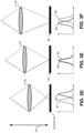
- FIGs. 3D-3F illustrate different intensity profiles from the dual photodiodes with respect to a focusing distance of a lens 339 adjusted along a z-axis 334 of the imaging system, in accordance with implementations of the disclosure.
- lens 339 is positioned along z-axis 334 at a distance too close to sensor 390 and therefore does not focus light to the imaging plane of sensor 390.
- the first intensity profile 381 is not aligned with the second intensity profile 382.
- the first intensity profile is generated by first-photodiodes of the dual-photodiode disparity image sensor and the second intensity profile is generated by second-photodiodes of the dual-photodiode disparity image sensor disposed adjacent to the first-photodiodes.
- lens 339 is positioned along z-axis 334 at a distance that focuses the light to the imaging plane of sensor 390 and the first intensity profile 383 is aligned with the second intensity profile 384.
- lens 339 is positioned along z-axis 334 at a distance too far from sensor 390 and therefore does not focus light to the imaging plane. Hence, the first intensity profile 385 is not aligned with the second intensity profile 386.
- the defocus of focusing lenses 239A and 293B can be measured in the captured adjustment image 297 by analyzing an alignment of a first intensity profile of the adjustment image and a second intensity profile of the adjustment image (where the first intensity profile is generated by first-photodiodes of the dual-photodiode disparity image sensor and the second intensity profile is generated by second-photodiodes of the dual-photodiode disparity image sensor 290).
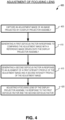
- FIG. 4 illustrates a flow chart of an example process 400 of adjusting a focusing lens.
- the order in which some or all of the process blocks appear in process 400 should not be deemed limiting. Rather, one of ordinary skill in the art having the benefit of the present disclosure will understand that some of the process blocks may be executed in a variety of orders not illustrated, or even in parallel. All or a portion of the process blocks in FIG. 4 may be executed by processing logic 107 or 207.
- an adjustment image (e.g. adjustment image 297) is captured.
- the adjustment image is of an image projected by a display projector assembly.
- the adjustment image is captured by a dual-photodiode disparity image sensor (e.g. image sensor 290 in some implementations).
- a first defocus factor is generated in response to comparing the adjustment image with a reference image driven onto the display projector assembly.
- a second defocus factor is generated in response to an alignment of a first intensity profile of the adjustment image and a second intensity profile of the adjustment image.
- the first intensity profile is generated by first-photodiodes of the dual-photodiode disparity image sensor and the second intensity profile is generated by second-photodiodes of the dual-photodiode disparity image sensor disposed adjacent to the first-photodiodes.
- a focusing lens (e.g. focusing lens 239A or 239B) is adjusted in response to the first defocus factor and the second defocus factor.
- the focusing lens is adjusted in response to only one defocus factor.
- a third defocus factor is generated in response to a thermal reading of the focusing lens of the display projector assembly and adjusting the focusing lens of the display projector assembly is also in response to the third defocus factor.
- thermal sensor 237A or 237 B may provide the thermal reading of the focusing lens to processing logic 207.
- the focusing lens of the display projector assembly is also adjusted in response to a position signal generated by a position sensor (e.g. 235A or 235B) that senses a position of the focusing lens (e.g. 239A or 239B) of the display projector assembly.
- a position sensor e.g. 235A or 235B
- generating the first defocus factor includes computing a relative peak signal to noise ratio (PSNR) between the adjustment image and the reference image and deriving the first defocus factor from the relative PSNR.
- PSNR peak signal to noise ratio
- FIG. 5 illustrates an example block diagram of an outer-loop control 510 and an inner-loop control 540 of adjusting a focusing lens.
- Inner-loop control 540 includes an actuator 555 and inner-loop logic 551.
- a position sensor e.g. position sensor 235
- Inner-loop logic 551 drives actuator 555 to adjust focusing lens 539 to a particular z-axis position in response to the position signal and a focus input from outer-loop logic 511.
- Lens 539 focuses the display light emitted by display 550.
- a temperature sensor 532 may sense a thermal reading 591 and provide the thermal reading 591 to thermal model 561.
- Thermal model 561 may provide a defocus factor 536 to defocus module 569.
- Thermal model 561 may be a linear model to generate the defocus factor 536.
- the linear model may be derived from factory calibration involving monitoring defocus over multiple temperature ranges and fitting a polynomial model to the response.
- Disparity Image Sensor 590 receives image light from display 550 in order to capture an adjustment image.
- Dual photodiode defocus data 593 may be provided to Photodiode Defocus module 563 from disparity image sensor 590. Based on intensity profiles of the dual photodiodes in disparity image sensor 590, photodiode defocus module 563 generates defocus factor 537.
- the adjustment image that disparity image sensor 590 captures may be sent to content-based analysis module 565 as frame 595. Based on frame 595, content-based analysis module 565 generates defocus factor 538. Content-based analysis module 565 may also receive a reference image that was driven onto display 550 and compare the reference image with frame 595 received from disparity image sensor 590 to generate defocus factor 538.
- defocus module 569 receives defocus factors 536, 537, and 538 and generates a defocus adjustment command 531 in response to one or more of the defocus factors 536, 537, and 538.
- Outer-loop logic 511 receives defocus adjustment command 531 and sends it to inner-loop logic 551 as a focus input.
- the z-position of lens 539 is influenced by both the inner-loop control 540 and the outer-loop control 510.
- FIG. 6 illustrates an example block diagram of an outer-loop control 610 for adjusting a focusing lens.
- Outer-loop control 610 differs from outer-loop control 510 in that the defocus factor 536 from thermal model 561 is fed forward to outer-loop logic 611 and defocus module 669 receives defocus factors 537 and 538.
- Defocus module 669 receives defocus factors 537 and 538 and generates a defocus adjustment command 631 in response to one or more of the defocus factors 537 and 538.
- Outer-loop logic 611 generates its focus input for providing to inner-loop logic 551 in response to defocus factor 536 and defocus adjustment command 631.
- the example architecture of FIG. 6 may offer improved dynamic performance as feedback from defocus factors 537 and 538 may only present smaller residual focusing errors compared to a dominant defocus estimation based on thermal modeling.
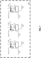
- FIG. 7 illustrates an example display 730 that includes three light sources 743A, 743B, and 743C.
- Light sources 743A, 743B, and 743C may be red, green, and blue light sources, respectively.
- the light sources may include lasers or LEDs, for example.
- more than one focusing lens in a display may be adjusted along a z-axis for defocus adjustment.
- focusing lens 739A moves along a z-position 774A of an optical axis of light source 743A to focus illumination light 771A emitted by light source 743A.
- Temperature sensor 737A may generate a thermal reading of focusing lens 739A and actuator 733A is configured to adjust focusing lens 739A along z-position 774A.
- focusing lens 739B moves along a z-position 774B of an optical axis of light source 743B to focus illumination light 771B emitted by light source 743B.
- Temperature sensor 737B may generate a thermal reading of focusing lens 739B and actuator 733B is configured to adjust focusing lens 739B along z-position 774B.
- focusing lens 739C moves along a z-position 774C of an optical axis of light source 743C to focus illumination light 771C emitted by light source 743C.
- Temperature sensor 737C may generate a thermal reading of focusing lens 73 9C and actuator 733C is configured to adjust focusing lens 739C along z-position 774C.
- defocusing adjustments may be made for each light source (and each corresponding wavelength) in a display 730.
- Embodiments of the invention may include or be implemented in conjunction with an artificial reality system.
- Artificial reality is a form of reality that has been adjusted in some manner before presentation to a user, which may include, e.g., a virtual reality (VR), an augmented reality (AR), a mixed reality (MR), a hybrid reality, or some combination and/or derivatives thereof.
- Artificial reality content may include completely generated content or generated content combined with captured (e.g., real-world) content.
- the artificial reality content may include video, audio, haptic feedback, or some combination thereof, and any of which may be presented in a single channel or in multiple channels (such as stereo video that produces a three-dimensional effect to the viewer).
- artificial reality may also be associated with applications, products, accessories, services, or some combination thereof, that are used to, e.g., create content in an artificial reality and/or are otherwise used in (e.g., perform activities in) an artificial reality.
- the artificial reality system that provides the artificial reality content may be implemented on various platforms, including a head-mounted display (HMD) connected to a host computer system, a standalone HMD, a mobile device or computing system, or any other hardware platform capable of providing artificial reality content to one or more viewers.
- HMD head-mounted display
- processing logic in this disclosure may include one or more processors, microprocessors, multi-core processors, Application-specific integrated circuits (ASIC), and/or Field Programmable Gate Arrays (FPGAs) to execute operations disclosed herein.
- memories are integrated into the processing logic to store instructions to execute operations and/or store data.
- Processing logic may also include analog or digital circuitry to perform the operations in accordance with embodiments of the disclosure.
- a “memory” or “memories” described in this disclosure may include one or more volatile or non-volatile memory architectures.
- the “memory” or “memories” may be removable and non-removable media implemented in any method or technology for storage of information such as computer-readable instructions, data structures, program modules, or other data.
- Example memory technologies may include RAM, ROM, EEPROM, flash memory, CD-ROM, digital versatile disks (DVD), high-definition multimedia/data storage disks, or other optical storage, magnetic cassettes, magnetic tape, magnetic disk storage or other magnetic storage devices, or any other non-transmission medium that can be used to store information for access by a computing device.
- Networks may include any network or network system such as, but not limited to, the following: a peer-to-peer network; a Local Area Network (LAN); a Wide Area Network (WAN); a public network, such as the Internet; a private network; a cellular network; a wireless network; a wired network; a wireless and wired combination network; and a satellite network.
- a peer-to-peer network such as, but not limited to, the following: a peer-to-peer network; a Local Area Network (LAN); a Wide Area Network (WAN); a public network, such as the Internet; a private network; a cellular network; a wireless network; a wired network; a wireless and wired combination network; and a satellite network.
- Communication channels may include or be routed through one or more wired or wireless communication utilizing IEEE 802.11 protocols, short-range wireless protocols, SPI (Serial Peripheral Interface), I 2 C (Inter-Integrated Circuit), USB (Universal Serial Port), CAN (Controller Area Network), cellular data protocols (e.g. 3G, 4G, LTE, 5G), optical communication networks, Internet Service Providers (ISPs), a peer-to-peer network, a Local Area Network (LAN), a Wide Area Network (WAN), a public network (e.g. "the Internet”), a private network, a satellite network, or otherwise.
- IEEE 802.11 protocols Short-range wireless protocols
- SPI Serial Peripheral Interface
- I 2 C Inter-Integrated Circuit
- USB Universal Serial Port
- CAN Controller Area Network
- cellular data protocols e.g. 3G, 4G, LTE, 5G
- optical communication networks e.g. 3G, 4G, LTE, 5G
- ISPs Internet Service Providers
- a computing device may include a desktop computer, a laptop computer, a tablet, a phablet, a smartphone, a feature phone, a server computer, or otherwise.
- a server computer may be located remotely in a data center or be stored locally.
- a tangible non-transitory machine-readable storage medium includes any mechanism that provides (i.e., stores) information in a form accessible by a machine (e.g., a computer, network device, personal digital assistant, manufacturing tool, any device with a set of one or more processors, etc.).
- a machine-readable storage medium includes recordable/non-recordable media (e.g., read only memory (ROM), random access memory (RAM), magnetic disk storage media, optical storage media, flash memory devices, etc.).
Landscapes
- Physics & Mathematics (AREA)
- General Physics & Mathematics (AREA)
- Optics & Photonics (AREA)
- Engineering & Computer Science (AREA)
- Multimedia (AREA)
- Signal Processing (AREA)
- Computer Hardware Design (AREA)
- Theoretical Computer Science (AREA)
Abstract
An adjustment image of a projected image is captured by a disparity image sensor. A first defocus factor in generated response to comparing the adjustment image with a reference image driven onto a display projector assembly the generated the projected image. A second defocus factor is generated in response to an alignment of a first intensity profile of the adjustment image and a second intensity profile of the adjustment image. A focusing lens of the display projector assembly is adjusted in response to at least one of the first defocus factor and the second defocus factor.
Description
- This disclosure relates generally to optics, and in particular to displays.
- Optical lenses are used to focus display light and also used to focus image light onto image sensors for imaging purposes. The focus of an optical lens may change with temperature. Furthermore, manufacturing tolerances of the lenses themselves or the alignment of lenses in a lens assembly may also contribute to unwanted performance variance.
- According to an aspect, there is provided a head mounted display comprising:
- a display projector assembly configured to present a virtual image to an eyebox region, wherein the display projector assembly includes a focusing lens configured to focus the virtual image to the eyebox region;
- a disparity waveguide configured to receive a portion of image light of the virtual image generated by the display projector assembly;
- a dual-photodiode disparity image sensor configured to capture an adjustment image from the image light propagating in the disparity waveguide; and
- processing logic configured to:
- generate a first defocus factor in response to comparing the adjustment image with a reference image driven onto the display projector assembly;
- generate a second defocus factor in response to an alignment of a first intensity profile of the adjustment image and a second intensity profile of the adjustment image; and
- adjust the focusing lens of the display projector assembly in response to:
- the first defocus factor; and
- the second defocus factor.
- The head mounted display may further comprise:
a temperature sensor configured to generate a thermal reading of the focusing lens of the display projector assembly, wherein the processing logic is further configured to: - generate a third defocus factor in response to thermal reading; and
- adjust the focusing lens in response to the third defocus factor.
- Adjusting the focusing lens of the display projector assembly may also be in response to a position signal generated by a position sensor that senses a position of the focusing lens of the display projector assembly.
- The display projector assembly may include a first light source, a second light source, and a third light source. Adjusting the focusing lens may include:
- adjusting a first focusing lens along a first optical axis of the first light source, wherein the first focusing lens receives first illumination light from the first light source;
- adjusting a second focusing lens along a second optical axis of the second light source, wherein the second focusing lens receives second illumination light from the second light source; and
- adjusting a third focusing lens along a third optical axis of the third light source, wherein the third focusing lens receives third illumination light from the third light source, the first illumination light, the second illumination light, and the third illumination light having different wavelengths.
- The first illumination light may be red. The second illumination light may be green. The third illumination light may be blue.
- Generating the first defocus factor may include:
- computing a relative peak signal to noise ratio (PSNR) between the adjustment image and the reference image; and
- deriving the first defocus factor from the relative PSNR.
- Adjusting the focusing lens of the display projector assembly may include adjusting the focusing lens along a z-axis with respect to a display of the display projector assembly.
- The head mounted display may further comprise a camera lens configured disposed between the disparity waveguide and the dual-photodiode disparity image sensor, wherein the camera lens is configured to focus the portion of image light of the virtual image onto an imaging plane of the dual-photodiode disparity image sensor,
The head mounted display may further comprise a display waveguide configured to receive the image light of the virtual image from the display projector assembly, wherein the disparity waveguide is configured to receive the portion of the image light of the virtual image from the display waveguide. - The first intensity profile may be generated by first-photodiodes of the dual-photodiode disparity image sensor. The second intensity profile may be generated by second-photodiodes of the dual-photodiode disparity image sensor disposed adjacent to the first-photodiodes.
- According to another aspect, there is provided a display assembly comprising:
- a display;
- a focusing lens configured to focus display light generated by the display;
- a dual-photodiode disparity image sensor configured to capture an adjustment image from the display light; and
- processing logic configured to:
- generate a first defocus factor in response to comparing the adjustment image with a reference image driven onto the display;
- generate a second defocus factor in response to an alignment of a first intensity profile of the adjustment image and a second intensity profile of the adjustment image; and
- adjust the focusing lens in response to:
- the first defocus factor; and
- the second defocus factor.
- The display assembly may further comprise:
a temperature sensor configured to generate a thermal reading of the focusing lens, wherein the processing logic is further configured to: - generate a third defocus factor in response to thermal reading; and
- adjust the focusing lens in response to the third defocus factor.
- Adjusting the focusing lens may also be in response to a position signal generated by a position sensor that senses a position of the focusing lens.
- According to a further aspect, there is provided a method comprising:
- capturing an adjustment image of an image projected by a display projector assembly, wherein the adjustment image is captured by a dual-photodiode disparity image sensor;
- generating a first defocus factor in response to comparing the adjustment image with a reference image driven onto the display projector assembly;
- generating a second defocus factor in response to an alignment of a first intensity profile of the adjustment image and a second intensity profile of the adjustment image, wherein the first intensity profile is generated by first-photodiodes of the dual-photodiode disparity image sensor, and wherein the second intensity profile is generated by second-photodiodes of the dual-photodiode disparity image sensor disposed adjacent to the first-photodiodes; and
- adjusting a focusing lens of the display projector assembly in response to the first defocus factor or the second defocus factor.
- The method may further comprise generating a third defocus factor in response to a thermal reading of the focusing lens of the display projector assembly, wherein the adjusting the focusing lens of the display projector assembly is also in response to the third defocus factor.
- The adjusting the focusing lens of the display projector assembly may also be in response to a position signal generated by a position sensor that senses a position of the focusing lens of the display projector assembly.
- Adjusting the focusing lens of a display projector may include:
- adjusting a first focusing lens along a first optical axis of a first light source, wherein the first focusing lens receives first illumination light from the first light source;
- adjusting a second focusing lens along a second optical axis of a second light source, wherein the second focusing lens receives second illumination light from the second light source; and
- adjusting a third focusing lens along a third optical axis of a third light source, wherein the third focusing lens receives third illumination light from the third light source, the first illumination light, the second illumination light, and the third illumination light having different wavelengths.
- The first illumination light may be red. The second illumination light may be green. The third illumination light may be blue.
- Generating the first defocus factor may include:
- computing a relative peak signal to noise ratio (PSNR) between the adjustment image and the reference image; and
- deriving the first defocus factor from the relative PSNR.
- Adjusting the focusing lens of the display projector assembly may include adjusting the focusing lens along a z-axis with respect to a display of the display projector assembly.
- It will be appreciated that any features described herein as being suitable for incorporation into one or more aspects or embodiments of the present disclosure are intended to be generalizable across any and all aspects and embodiments of the present disclosure. Other aspects of the present disclosure can be understood by those skilled in the art in light of the description, the claims, and the drawings of the present disclosure. The foregoing general description and the following detailed description are exemplary and explanatory only and are not restrictive of the claims.
- Non-limiting and non-exhaustive embodiments of the invention are described with reference to the following figures, wherein like reference numerals refer to like parts throughout the various views unless otherwise specified.
-
FIG. 1 illustrates a head mounted display (HMD) that may include a display assembly with an adjustable focusing lens. -
FIG. 2 illustrates an example display assembly having active defocus capability that may be included in an HMD. -
FIGs. 3A-3C illustrate example virtual images and an example adjustment image captured by a disparity image sensor. -
FIG. 3D-3F illustrates different intensity profiles from the dual photodiodes with respect to a focusing distance of a lens adjusted along a z-axis of the imaging system. -
FIG. 4 illustrates a flow chart of an example process of adjusting a focusing lens. -
FIG. 5 illustrates an example block diagram of an outer-loop control and an inner-loop control of adjusting a focusing lens. -
FIG. 6 illustrates an example block diagram of another outer-loop control for adjusting a focusing lens. -
FIG. 7 illustrates an example display that includes three light sources. - Embodiments of active defocusing for a display assembly are described herein. In the following description, numerous specific details are set forth to provide a thorough understanding of the embodiments. One skilled in the relevant art will recognize, however, that the techniques described herein can be practiced without one or more of the specific details, or with other methods, components, materials, etc. In other instances, well-known structures, materials, or operations are not shown or described in detail to avoid obscuring certain aspects.
- Reference throughout this specification to "one embodiment" or "an embodiment" means that a particular feature, structure, or characteristic described in connection with the embodiment is included in at least one embodiment of the present invention. Thus, the appearances of the phrases "in one embodiment" or "in an embodiment" in various places throughout this specification are not necessarily all referring to the same embodiment. Furthermore, the particular features, structures, or characteristics may be combined in any suitable manner in one or more embodiments.
- In some implementations of the disclosure, the term "near-eye" may be defined as including an element that is configured to be placed within 50 mm of an eye of a user while a near-eye device is being utilized. Therefore, a "near-eye optical element" or a "near-eye system" would include one or more elements configured to be placed within 50 mm of the eye of the user.
- In accordance with this disclosure, visible light may be defined as having a wavelength range of approximately 380 nm - 700 nm. Non-visible light may be defined as light having wavelengths that are outside the visible light range, such as ultraviolet light and infrared light. Infrared light having a wavelength range of approximately 700 nm - 1 mm includes near-infrared light. In accordance with this disclosure, near-infrared light may be defined as having a wavelength range of approximately 700 nm - 1.6 µm.
- In accordance with this disclosure, the term "transparent" may be defined as having greater than 90% transmission of light. In accordance with this disclosure, the term "transparent" may be defined as a material having greater than 90% transmission of visible light.
- Display projector assemblies include focusing lenses to focus the display light. One way to increase brightness in a display projector assembly is to utilize a "faster" focusing lens with a smaller F-stop. However, these faster lenses also have a smaller depth of field that makes it more sensitive to focal length as a function of temperature. Additionally, coefficient of thermal expansion (CTE) mismatches in lens element in the focusing lens assembly may cause focal length shifts with temperatures. Furthermore, factory tolerances and manufacturing alignment tolerances may also have an impact on the system focusing performance of the system. Thus, focusing the display projector assembly with faster lenses that increase brightness may use enhanced defocusing adjustment to assist in improving the display of images.
- Implementations of the disclosure include adjusting a focusing lens of a display assembly in response to multiple defocus factors. A content-based defocus factor may be generated in response to compare an adjustment image (captured by an image sensor) with a reference image that was actually driven onto the display assembly. A dual-photodiode defocus factor may be generated in response to an alignment of a first intensity profile of the adjustment image and a second intensity profile of the adjustment image that is captured by the dual-photodiode disparity image sensor. These and other embodiments are described in more detail in connection with
FIGs. 1-7 . -
FIG. 1 illustrates a head mounted display (HMD) 100 that may include a display assembly with an adjustable focusing lens.HMD 100 includesframe 114 coupled toarms Lens assemblies Lens assemblies HMD 100. The illustratedHMD 100 is configured to be worn on or about a head of a wearer ofHMD 100. - In the
HMD 100 illustrated inFIG. 1 , eachlens assembly 121A/121B includes adisplay waveguide 150A/150B to direct image light generated bydisplay projector assemblies 130A/130B to an eyebox region for viewing by a user ofHMD 100.Display projector assemblies 130A/130B may include a beam-scanning display that includes a scanning mirror, for example.Display projector assemblies 130A/130B may include one or more light sources such as a red, green, and blue light source. -
Lens assemblies waveguides 150A/150B.Lens assemblies display projector assemblies HMD 100. In an embodiment, bothdisplay projector assemblies waveguides -
Frame 114 andarms 111A/111B may include supporting hardware ofHMD 100 such as processing logic 107, wired and/or wireless data interface for sending and receiving data, graphic processors, and one or more memories for storing data and computer-executable instructions. Processing logic 107 may include circuitry, logic, instructions stored in a machine-readable storage medium, ASIC circuitry, FPGA circuity, and/or one or more processors. In one embodiment,HMD 100 may be configured to receive wired power. In one embodiment,HMD 100 is configured to be powered by one or more batteries. In one embodiment,HMD 100 may be configured to receive wired data including video data via a wired communication channel. In one embodiment,HMD 100 is configured to receive wireless data including video data via a wireless communication channel. - Processing logic 107 is illustrated as included in
arm 111A ofHMD 100, although processing logic 107 may be disposed anywhere in theframe 114 orarms 111A/111B ofHMD 100. Processing logic 107 may be communicatively coupled to wired orwireless network 180. Processing logic 107 may be configured to adjust a focusing lens ofdisplay projector assemblies 130A and/or 130B in response to defocus factors. -
FIG. 2 illustrates anexample display assembly 200 having active defocus capability that may be included in an HMD such asHMD 100.Display assembly 200 includes twodisplay waveguides disparity image sensor 290 configured to receive a portion of the image light indisplay waveguide disparity waveguide 270. - An example left display projector assembly may include
display 230A and focusinglens 239A that can be adjusted along z-axis 234A to provide defocusing functionality to the display projector assembly. Z-axis 234A may correspond to an optical axis of image light emitted bydisplay 230A andactuator 233A is configured to adjust focusinglens 239A along positions of z-axis 234A.Actuator 233A may include a micro-electro-mechanical systems (MEMS) actuator or a piezo device, for example.Processing logic 207 may be configured to driveactuator 233A in response to one or more defocus factors. Aposition sensor 235A may generate a positional signal that indicates a position of focusinglens 239A and provide the position signal toprocessing logic 207 by way of communication channel X2. In the illustrated implementation, atemperature sensor 237A is configured to generate a thermal reading of focusinglens 239A of the display projector assembly and provide the thermal reading toprocessing logic 207. - In operation, an
image 220A is driven ontodisplay 230A anddisplay 230A generates image light 231A to direct intodisplay waveguide 250A for presenting a virtual image to an eyebox region. Theimage light 231A may be confined to propagate withindisplay waveguide 250A by way of total internal reflection (TIR) or otherwise. The image light is outcoupled (not specifically illustrated) fromdisplay waveguide 250A to present a virtual image to an eyebox region. An outcoupling element (not illustrated) such a grating or a holographic optical element (HOE) may be used to outcouple the image light to the eyebox region, for example. - In
FIG. 2 , at least a portion of the image light propagating indisplay waveguide 250A is outcoupled intodisparity waveguide 270.Outcoupler 251A outcouples the image light fromdisplay waveguide 250A andincoupler 271A incouples the image light intodisparity waveguide 270. The image light propagates in disparity waveguide until it is outcoupled byoutcoupler 273 wherecamera lens assembly 280 focuses the image light to an imaging plane ofdisparity image sensor 290.Disparity image sensor 290 captures anadjustment image 297 from the image light.Disparity image sensor 290 may include a complementary metal-oxide semiconductor (CMOS) image sensor, for example. -
Disparity image sensor 290 also receives image light from a second display project assembly in the illustrated implementation ofFIG. 2 . The second display projector assembly includesdisplay 230B and focusinglens 239B and operates similarly to the first display projector assembly on the left side ofFIG. 2 . - Example right display projector assembly may include
display 230B and focusinglens 239B that can be adjusted along z-axis 234B to provide defocusing functionality to the display projector assembly. Z-axis 234B may correspond to an optical axis of image light emitted bydisplay 230B andactuator 233B is configured to adjust focusinglens 239B along positions of z-axis 234B.Actuator 233B may include a micro-electro-mechanical systems (MEMS) actuator or a piezo device, for example.Processing logic 207 may be configured to driveactuator 233B in response to one or more defocus factors. A position sensor 235B may generate a positional signal that indicates a position of focusinglens 239B and provide the position signal toprocessing logic 207 by way of communication channel X3. In the illustrated implementation, atemperature sensor 237B is configured to generate a thermal reading of focusinglens 239B of the right display projector assembly and provide the thermal reading toprocessing logic 207. - In operation, an
image 220B is driven ontodisplay 230B anddisplay 230B generates image light 231B to direct intodisplay waveguide 250A for presenting a virtual image to an eyebox region. Theimage light 231B may be confined to propagate withindisplay waveguide 250B by way of total internal reflection (TIR) or otherwise. The image light is outcoupled (not specifically illustrated) fromdisplay waveguide 250B to present a virtual image to an eyebox region. An outcoupling element (not illustrated) such a grating or a holographic optical element (HOE) may be used to outcouple the image light to the eyebox region, for example. - In
FIG. 2 , at least a portion of the image light propagating indisplay waveguide 250B is outcoupled intodisparity waveguide 270.Outcoupler 251B outcouples the image light fromdisplay waveguide 250B andincoupler 271B incouples the image light intodisparity waveguide 270. The image light propagates in disparity waveguide until it is outcoupled byoutcoupler 273 wherecamera lens assembly 280 focuses the image light to an imaging plane ofdisparity image sensor 290. - The
adjustment image 297 captured bydisparity image sensor 290 may include a portion of theimage light 231A fromdisplay waveguide 250A and a portion of the image light 231B fromdisplay waveguide 250B. -
FIG. 3A illustrates an example of avirtual image 320A that may be driven ontodisplay 230A asimage 220A.FIG. 3C illustrates an example of avirtual image 320B that may be driven ontodisplay 230B asimage 220B.FIG. 3B illustrates anexample adjustment image 397 captured bydisparity image sensor 290. Theexample adjustment image 397 is illustrated as a slightly out of focus and blurred image of a tiger.Adjustment image 397 is an example of theadjustment image 297 that may be captured bydisparity image sensor 290. When focusinglenses adjustment image 297/397 will be in focus and not blurry. - Referring again to
FIG. 2 ,processing logic 207 is configured to receiveadjustment image 297 by way of communication channel X1.Processing logic 207 may adjust focusinglens 239A and/or 239B in response toadjustment image 297. - In an implementation,
processing logic 207 generates a content-based defocus factor in response to comparingadjustment image 297 to a reference image (e.g. image - In an implementation,
processing logic 207 generates a second defocus factor in response to intensity profiles from a dual-photodiode disparity image sensor that is used asdisparity image sensor 290.FIG. 2 illustrates a plan view of a section of anexample image sensor 290 having Red-Green-Green-Blue (RGGB)pixels 291. In a dual-photodiode disparity image sensor, each red subpixel includes two adjacent photodiodes configured to sense incident red light, each green subpixel includes two adjacent photodiodes configured to sense incident green light, and each blue subpixel includes two adjacent photodiodes configured to sense incident blue light. Having dual photodiodes in each subpixel allows the dual-photodiode disparity image sensor to provide defocus information from the different intensity profiles generated by the two photodiodes in the subpixels. -
FIGs. 3D-3F illustrate different intensity profiles from the dual photodiodes with respect to a focusing distance of alens 339 adjusted along a z-axis 334 of the imaging system, in accordance with implementations of the disclosure. InFIG. 3D ,lens 339 is positioned along z-axis 334 at a distance too close tosensor 390 and therefore does not focus light to the imaging plane ofsensor 390. Hence, thefirst intensity profile 381 is not aligned with thesecond intensity profile 382. The first intensity profile is generated by first-photodiodes of the dual-photodiode disparity image sensor and the second intensity profile is generated by second-photodiodes of the dual-photodiode disparity image sensor disposed adjacent to the first-photodiodes. - In
FIG. 3E lens 339 is positioned along z-axis 334 at a distance that focuses the light to the imaging plane ofsensor 390 and thefirst intensity profile 383 is aligned with thesecond intensity profile 384. InFIG. 3F ,lens 339 is positioned along z-axis 334 at a distance too far fromsensor 390 and therefore does not focus light to the imaging plane. Hence, thefirst intensity profile 385 is not aligned with thesecond intensity profile 386. - While the optical path between focusing
lenses disparity image sensor 290 inFIG. 2 is not as direct as the simplified drawings ofFIG. 3D-3F , the same principle applies. Thus, the defocus of focusinglenses 239A and 293B can be measured in the capturedadjustment image 297 by analyzing an alignment of a first intensity profile of the adjustment image and a second intensity profile of the adjustment image (where the first intensity profile is generated by first-photodiodes of the dual-photodiode disparity image sensor and the second intensity profile is generated by second-photodiodes of the dual-photodiode disparity image sensor 290). -
FIG. 4 illustrates a flow chart of anexample process 400 of adjusting a focusing lens. The order in which some or all of the process blocks appear inprocess 400 should not be deemed limiting. Rather, one of ordinary skill in the art having the benefit of the present disclosure will understand that some of the process blocks may be executed in a variety of orders not illustrated, or even in parallel. All or a portion of the process blocks inFIG. 4 may be executed by processinglogic 107 or 207. - In
process block 405, an adjustment image (e.g. adjustment image 297) is captured. The adjustment image is of an image projected by a display projector assembly. The adjustment image is captured by a dual-photodiode disparity image sensor (e.g. image sensor 290 in some implementations). - In
process block 410, a first defocus factor is generated in response to comparing the adjustment image with a reference image driven onto the display projector assembly. - In
process block 415, a second defocus factor is generated in response to an alignment of a first intensity profile of the adjustment image and a second intensity profile of the adjustment image. The first intensity profile is generated by first-photodiodes of the dual-photodiode disparity image sensor and the second intensity profile is generated by second-photodiodes of the dual-photodiode disparity image sensor disposed adjacent to the first-photodiodes. - In
process block 420, a focusing lens (e.g. focusing lens - In an implementation of
process 400, a third defocus factor is generated in response to a thermal reading of the focusing lens of the display projector assembly and adjusting the focusing lens of the display projector assembly is also in response to the third defocus factor. In the example ofFIG. 2 ,thermal sensor processing logic 207. - In an implementation of
process 400, the focusing lens of the display projector assembly is also adjusted in response to a position signal generated by a position sensor (e.g. 235A or 235B) that senses a position of the focusing lens (e.g. 239A or 239B) of the display projector assembly. - In an implementation, generating the first defocus factor includes computing a relative peak signal to noise ratio (PSNR) between the adjustment image and the reference image and deriving the first defocus factor from the relative PSNR.
-
FIG. 5 illustrates an example block diagram of an outer-loop control 510 and an inner-loop control 540 of adjusting a focusing lens. Inner-loop control 540 includes anactuator 555 and inner-loop logic 551. A position sensor (e.g. position sensor 235) may provide a z-position oflens 539 to inner-loop logic 551. Inner-loop logic 551 drives actuator 555 to adjust focusinglens 539 to a particular z-axis position in response to the position signal and a focus input from outer-loop logic 511.Lens 539 focuses the display light emitted bydisplay 550. - A
temperature sensor 532 may sense a thermal reading 591 and provide the thermal reading 591 tothermal model 561.Thermal model 561 may provide adefocus factor 536 to defocusmodule 569.Thermal model 561 may be a linear model to generate thedefocus factor 536. The linear model may be derived from factory calibration involving monitoring defocus over multiple temperature ranges and fitting a polynomial model to the response. -
Disparity Image Sensor 590 receives image light fromdisplay 550 in order to capture an adjustment image. Dualphotodiode defocus data 593 may be provided to Photodiode Defocus module 563 fromdisparity image sensor 590. Based on intensity profiles of the dual photodiodes indisparity image sensor 590, photodiode defocus module 563 generatesdefocus factor 537. - The adjustment image that
disparity image sensor 590 captures may be sent to content-basedanalysis module 565 asframe 595. Based onframe 595, content-basedanalysis module 565 generatesdefocus factor 538. Content-basedanalysis module 565 may also receive a reference image that was driven ontodisplay 550 and compare the reference image withframe 595 received fromdisparity image sensor 590 to generatedefocus factor 538. - In
FIG. 5 ,defocus module 569 receivesdefocus factors defocus adjustment command 531 in response to one or more of the defocus factors 536, 537, and 538. Outer-loop logic 511 receivesdefocus adjustment command 531 and sends it to inner-loop logic 551 as a focus input. Thus, the z-position oflens 539 is influenced by both the inner-loop control 540 and the outer-loop control 510. -
FIG. 6 illustrates an example block diagram of an outer-loop control 610 for adjusting a focusing lens. Outer-loop control 610 differs from outer-loop control 510 in that thedefocus factor 536 fromthermal model 561 is fed forward to outer-loop logic 611 anddefocus module 669 receivesdefocus factors Defocus module 669 receivesdefocus factors defocus adjustment command 631 in response to one or more of the defocus factors 537 and 538. Outer-loop logic 611 generates its focus input for providing to inner-loop logic 551 in response to defocusfactor 536 and defocusadjustment command 631. The example architecture ofFIG. 6 may offer improved dynamic performance as feedback fromdefocus factors -
FIG. 7 illustrates anexample display 730 that includes threelight sources Light sources - In
FIG. 7 , focusinglens 739A moves along a z-position 774A of an optical axis oflight source 743A to focus illumination light 771A emitted bylight source 743A.Temperature sensor 737A may generate a thermal reading of focusinglens 739A andactuator 733A is configured to adjust focusinglens 739A along z-position 774A. Similarly, focusinglens 739B moves along a z-position 774B of an optical axis oflight source 743B to focus illumination light 771B emitted bylight source 743B.Temperature sensor 737B may generate a thermal reading of focusinglens 739B andactuator 733B is configured to adjust focusinglens 739B along z-position 774B. And, focusinglens 739C moves along a z-position 774C of an optical axis oflight source 743C to focus illumination light 771C emitted bylight source 743C.Temperature sensor 737C may generate a thermal reading of focusing lens 73 9C andactuator 733C is configured to adjust focusinglens 739C along z-position 774C. Thus, defocusing adjustments may be made for each light source (and each corresponding wavelength) in adisplay 730. - Embodiments of the invention may include or be implemented in conjunction with an artificial reality system. Artificial reality is a form of reality that has been adjusted in some manner before presentation to a user, which may include, e.g., a virtual reality (VR), an augmented reality (AR), a mixed reality (MR), a hybrid reality, or some combination and/or derivatives thereof. Artificial reality content may include completely generated content or generated content combined with captured (e.g., real-world) content. The artificial reality content may include video, audio, haptic feedback, or some combination thereof, and any of which may be presented in a single channel or in multiple channels (such as stereo video that produces a three-dimensional effect to the viewer). Additionally, in some embodiments, artificial reality may also be associated with applications, products, accessories, services, or some combination thereof, that are used to, e.g., create content in an artificial reality and/or are otherwise used in (e.g., perform activities in) an artificial reality. The artificial reality system that provides the artificial reality content may be implemented on various platforms, including a head-mounted display (HMD) connected to a host computer system, a standalone HMD, a mobile device or computing system, or any other hardware platform capable of providing artificial reality content to one or more viewers.
- The term "processing logic" in this disclosure may include one or more processors, microprocessors, multi-core processors, Application-specific integrated circuits (ASIC), and/or Field Programmable Gate Arrays (FPGAs) to execute operations disclosed herein. In some embodiments, memories (not illustrated) are integrated into the processing logic to store instructions to execute operations and/or store data. Processing logic may also include analog or digital circuitry to perform the operations in accordance with embodiments of the disclosure.
- A "memory" or "memories" described in this disclosure may include one or more volatile or non-volatile memory architectures. The "memory" or "memories" may be removable and non-removable media implemented in any method or technology for storage of information such as computer-readable instructions, data structures, program modules, or other data. Example memory technologies may include RAM, ROM, EEPROM, flash memory, CD-ROM, digital versatile disks (DVD), high-definition multimedia/data storage disks, or other optical storage, magnetic cassettes, magnetic tape, magnetic disk storage or other magnetic storage devices, or any other non-transmission medium that can be used to store information for access by a computing device.
- Networks may include any network or network system such as, but not limited to, the following: a peer-to-peer network; a Local Area Network (LAN); a Wide Area Network (WAN); a public network, such as the Internet; a private network; a cellular network; a wireless network; a wired network; a wireless and wired combination network; and a satellite network.
- Communication channels may include or be routed through one or more wired or wireless communication utilizing IEEE 802.11 protocols, short-range wireless protocols, SPI (Serial Peripheral Interface), I2C (Inter-Integrated Circuit), USB (Universal Serial Port), CAN (Controller Area Network), cellular data protocols (e.g. 3G, 4G, LTE, 5G), optical communication networks, Internet Service Providers (ISPs), a peer-to-peer network, a Local Area Network (LAN), a Wide Area Network (WAN), a public network (e.g. "the Internet"), a private network, a satellite network, or otherwise.
- A computing device may include a desktop computer, a laptop computer, a tablet, a phablet, a smartphone, a feature phone, a server computer, or otherwise. A server computer may be located remotely in a data center or be stored locally.
- The processes explained above are described in terms of computer software and hardware. The techniques described may constitute machine-executable instructions embodied within a tangible or non-transitory machine (e.g., computer) readable storage medium, that when executed by a machine will cause the machine to perform the operations described. Additionally, the processes may be embodied within hardware, such as an application specific integrated circuit ("ASIC") or otherwise.
- A tangible non-transitory machine-readable storage medium includes any mechanism that provides (i.e., stores) information in a form accessible by a machine (e.g., a computer, network device, personal digital assistant, manufacturing tool, any device with a set of one or more processors, etc.). For example, a machine-readable storage medium includes recordable/non-recordable media (e.g., read only memory (ROM), random access memory (RAM), magnetic disk storage media, optical storage media, flash memory devices, etc.).
- The above description of illustrated embodiments of the invention, including what is described in the Abstract, is not intended to be exhaustive or to limit the invention to the precise forms disclosed. While specific embodiments of, and examples for, the invention are described herein for illustrative purposes, various modifications are possible within the scope of the invention, as those skilled in the relevant art will recognize.
- These modifications can be made to the invention in light of the above detailed description. The terms used in the following claims should not be construed to limit the invention to the specific embodiments disclosed in the specification. Rather, the scope of the invention is to be determined entirely by the following claims, which are to be construed in accordance with established doctrines of claim interpretation.
Claims (15)
- A head mounted display comprising:a display projector assembly configured to present a virtual image to an eyebox region, wherein the display projector assembly includes a focusing lens configured to focus the virtual image to the eyebox region;a disparity waveguide configured to receive a portion of image light of the virtual image generated by the display projector assembly;a dual-photodiode disparity image sensor configured to capture an adjustment image from the image light propagating in the disparity waveguide; andprocessing logic configured to:generate a first defocus factor in response to comparing the adjustment image with a reference image driven onto the display projector assembly;generate a second defocus factor in response to an alignment of a first intensity profile of the adjustment image and a second intensity profile of the adjustment image; andadjust the focusing lens of the display projector assembly in response to:the first defocus factor; andthe second defocus factor.
- The head mounted display of claim 1 further comprising:
a temperature sensor configured to generate a thermal reading of the focusing lens of the display projector assembly, wherein the processing logic is further configured to:generate a third defocus factor in response to thermal reading; andadjust the focusing lens in response to the third defocus factor. - The head mounted display of claim 1 or claim 2, wherein the adjusting the focusing lens of the display projector assembly is also in response to a position signal generated by a position sensor that senses a position of the focusing lens of the display projector assembly.
- The head mounted display of any preceding claim, wherein the display projector assembly includes a first light source, a second light source, and a third light source, and wherein adjusting the focusing lens includes:adjusting a first focusing lens along a first optical axis of the first light source, wherein the first focusing lens receives first illumination light from the first light source;adjusting a second focusing lens along a second optical axis of the second light source, wherein the second focusing lens receives second illumination light from the second light source; andadjusting a third focusing lens along a third optical axis of the third light source, wherein the third focusing lens receives third illumination light from the third light source, the first illumination light, the second illumination light, and the third illumination light having different wavelengths.
- The head mounted display of claim 4, wherein the first illumination light is red, the second illumination light is green, and the third illumination light is blue.
- The head mounted display of any preceding claim, wherein generating the first defocus factor includes:computing a relative peak signal to noise ratio, PSNR, between the adjustment image and the reference image; andderiving the first defocus factor from the relative PSNR.
- The head mounted display of any preceding claim, wherein adjusting the focusing lens of the display projector assembly includes adjusting the focusing lens along a z-axis with respect to a display of the display projector assembly.
- The head mounted display of any preceding claim further comprising:a camera lens configured disposed between the disparity waveguide and the dual-photodiode disparity image sensor, wherein the camera lens is configured to focus the portion of image light of the virtual image onto an imaging plane of the dual-photodiode disparity image sensor,
and/ora display waveguide configured to receive the image light of the virtual image from the display projector assembly, wherein the disparity waveguide is configured to receive the portion of the image light of the virtual image from the display waveguide. - The head mounted display of any preceding claim, wherein the first intensity profile is generated by first-photodiodes of the dual-photodiode disparity image sensor, and wherein the second intensity profile is generated by second-photodiodes of the dual-photodiode disparity image sensor disposed adjacent to the first-photodiodes.
- A display assembly comprising:a display;a focusing lens configured to focus display light generated by the display;a dual-photodiode disparity image sensor configured to capture an adjustment image from the display light; andprocessing logic configured to:generate a first defocus factor in response to comparing the adjustment image with a reference image driven onto the display;generate a second defocus factor in response to an alignment of a first intensity profile of the adjustment image and a second intensity profile of the adjustment image; andadjust the focusing lens in response to:the first defocus factor; andthe second defocus factor.
- The display assembly of claim 10 further comprising:
a temperature sensor configured to generate a thermal reading of the focusing lens, wherein the processing logic is further configured to:generate a third defocus factor in response to thermal reading; andadjust the focusing lens in response to the third defocus factor,
and/orwherein the adjusting the focusing lens is also in response to a position signal generated by a position sensor that senses a position of the focusing lens. - A method comprising:capturing an adjustment image of an image projected by a display projector assembly, wherein the adjustment image is captured by a dual-photodiode disparity image sensor;generating a first defocus factor in response to comparing the adjustment image with a reference image driven onto the display projector assembly;generating a second defocus factor in response to an alignment of a first intensity profile of the adjustment image and a second intensity profile of the adjustment image, wherein the first intensity profile is generated by first-photodiodes of the dual-photodiode disparity image sensor, and wherein the second intensity profile is generated by second-photodiodes of the dual-photodiode disparity image sensor disposed adjacent to the first-photodiodes; andadjusting a focusing lens of the display projector assembly in response to the first defocus factor or the second defocus factor.
- The method of claim 12 further comprising:generating a third defocus factor in response to a thermal reading of the focusing lens of the display projector assembly, wherein the adjusting the focusing lens of the display projector assembly is also in response to the third defocus factor,
and/orwherein the adjusting the focusing lens of the display projector assembly is also in response to a position signal generated by a position sensor that senses a position of the focusing lens of the display projector assembly. - The method of claim 12 or claim 13, wherein adjusting the focusing lens of a display projector includes:adjusting a first focusing lens along a first optical axis of a first light source, wherein the first focusing lens receives first illumination light from the first light source;adjusting a second focusing lens along a second optical axis of a second light source, wherein the second focusing lens receives second illumination light from the second light source; andadjusting a third focusing lens along a third optical axis of a third light source, wherein the third focusing lens receives third illumination light from the third light source, the first illumination light, the second illumination light, and the third illumination light having different wavelengths,and optionally wherein:
the first illumination light is red, the second illumination light is green, and the third illumination light is blue. - The method of any of claims 12 to 14, wherein generating the first defocus factor includes:computing a relative peak signal to noise ratio, PSNR, between the adjustment image and the reference image; andderiving the first defocus factor from the relative PSNR
and/orwherein adjusting the focusing lens of the display projector assembly includes adjusting the focusing lens along a z-axis with respect to a display of the display projector assembly.
Applications Claiming Priority (2)
| Application Number | Priority Date | Filing Date | Title |
|---|---|---|---|
| US202363462920P | 2023-04-28 | 2023-04-28 | |
| US18/201,547 US12399344B2 (en) | 2023-04-28 | 2023-05-24 | Active defocus for display assembly |
Publications (1)
| Publication Number | Publication Date |
|---|---|
| EP4455764A1 true EP4455764A1 (en) | 2024-10-30 |
Family
ID=90364841
Family Applications (1)
| Application Number | Title | Priority Date | Filing Date |
|---|---|---|---|
| EP24162615.9A Pending EP4455764A1 (en) | 2023-04-28 | 2024-03-11 | Active defocus for display assembly |
Country Status (2)
| Country | Link |
|---|---|
| US (2) | US12399344B2 (en) |
| EP (1) | EP4455764A1 (en) |
Families Citing this family (1)
| Publication number | Priority date | Publication date | Assignee | Title |
|---|---|---|---|---|
| EP4483227A1 (en) * | 2022-02-22 | 2025-01-01 | BAE SYSTEMS plc | Improvements in or relating to waveguide display systems |
Citations (2)
| Publication number | Priority date | Publication date | Assignee | Title |
|---|---|---|---|---|
| US20160150154A1 (en) * | 2013-09-30 | 2016-05-26 | Beijing Zhigu Rui Tuo Tech Co., Ltd | Imaging to facilitate object gaze |
| US20230085129A1 (en) * | 2021-09-10 | 2023-03-16 | Samsung Electronics Co., Ltd. | Electronic device and operating method thereof |
Family Cites Families (11)
| Publication number | Priority date | Publication date | Assignee | Title |
|---|---|---|---|---|
| JP5119567B2 (en) * | 2004-09-30 | 2013-01-16 | カシオ計算機株式会社 | camera |
| WO2007109856A1 (en) * | 2006-03-29 | 2007-10-04 | Curtin University Of Technology | Testing surveillance camera installations |
| US9756264B2 (en) * | 2009-03-02 | 2017-09-05 | Flir Systems, Inc. | Anomalous pixel detection |
| US9900526B2 (en) * | 2011-06-10 | 2018-02-20 | Flir Systems, Inc. | Techniques to compensate for calibration drifts in infrared imaging devices |
| WO2017104774A1 (en) * | 2015-12-18 | 2017-06-22 | 旭化成エレクトロニクス株式会社 | Drive device, lens unit, device, correction method, and program |
| KR102694982B1 (en) * | 2016-06-10 | 2024-08-14 | 삼성전자주식회사 | An electronic device and control method thereof |
| CN106488137A (en) * | 2016-11-29 | 2017-03-08 | 广东欧珀移动通信有限公司 | Dual camera focusing method, device and terminal equipment |
| JP7104296B2 (en) * | 2017-08-09 | 2022-07-21 | ミツミ電機株式会社 | Rangefinder camera |
| US10397465B2 (en) * | 2017-09-01 | 2019-08-27 | Qualcomm Incorporated | Extended or full-density phase-detection autofocus control |
| US11202043B1 (en) | 2020-08-25 | 2021-12-14 | Facebook Technologies, Llc | Self-testing display device |
| US11765470B2 (en) * | 2020-10-26 | 2023-09-19 | Samsung Electronics Co., Ltd. | Pixel array including evenly arranged phase detection pixels and image sensor including the pixel array |
-
2023
- 2023-05-24 US US18/201,547 patent/US12399344B2/en active Active
-
2024
- 2024-03-11 EP EP24162615.9A patent/EP4455764A1/en active Pending
-
2025
- 2025-07-30 US US19/284,673 patent/US20250355216A1/en active Pending
Patent Citations (2)
| Publication number | Priority date | Publication date | Assignee | Title |
|---|---|---|---|---|
| US20160150154A1 (en) * | 2013-09-30 | 2016-05-26 | Beijing Zhigu Rui Tuo Tech Co., Ltd | Imaging to facilitate object gaze |
| US20230085129A1 (en) * | 2021-09-10 | 2023-03-16 | Samsung Electronics Co., Ltd. | Electronic device and operating method thereof |
Non-Patent Citations (1)
| Title |
|---|
| EBNER CHRISTOPH ET AL: "Video See-Through Mixed Reality with Focus Cues", IEEE TRANSACTIONS ON VISUALIZATION AND COMPUTER GRAPHICS, IEEE, USA, vol. 28, no. 5, 15 February 2022 (2022-02-15), pages 2256 - 2266, XP011905552, ISSN: 1077-2626, [retrieved on 20220215], DOI: 10.1109/TVCG.2022.3150504 * |
Also Published As
| Publication number | Publication date |
|---|---|
| US20240361566A1 (en) | 2024-10-31 |
| US20250355216A1 (en) | 2025-11-20 |
| US12399344B2 (en) | 2025-08-26 |
Similar Documents
| Publication | Publication Date | Title |
|---|---|---|
| US9569897B2 (en) | Head mounted display and optical position adjustment method of the same | |
| US8817379B2 (en) | Whole image scanning mirror display system | |
| EP4107571B1 (en) | Dual wavelength eye imaging | |
| TW201907204A (en) | Method and system for aligning between an external scene and a virtual image | |
| US20230119935A1 (en) | Gaze-guided image capture | |
| US10045005B2 (en) | 3D camera module | |
| US11048091B1 (en) | Wide-field image light and inset image light for head mounted displays | |
| US20250355216A1 (en) | Disparity sensing and adjustment | |
| KR101976463B1 (en) | Apparatus and method of generating 3-dimensional image | |
| US20230205312A1 (en) | Waveguide imaging system for eye tracking | |
| US12196976B2 (en) | Multi-directional gratings in a waveguide system | |
| US20230324686A1 (en) | Adaptive control of optical transmission | |
| CN118859529A (en) | Active defocus for display components | |
| JP2015012442A (en) | Imaging apparatus, imaging method, image generation apparatus, image generation method, and program | |
| JP7719886B2 (en) | Binocular alignment of rigid frames for near-eye displays | |
| US12147596B1 (en) | Event sensing and tracking | |
| US12493191B2 (en) | Multi-directional waveguide eye tracking system | |
| US12512027B2 (en) | Contrast ratio adjustment in multi-application augmented reality environment | |
| CN115236855A (en) | Display device including a freely formed surface and method of operating the same | |
| US20250148642A1 (en) | Calibration of eye tracking system | |
| US12572016B1 (en) | Waveguide alignment with scanner | |
| US20240264456A1 (en) | Accommodation state of eye from polarized imaging | |
| US11778366B2 (en) | Gaze-guided audio | |
| JP5399986B2 (en) | Imaging apparatus and image processing method | |
| TW202331357A (en) | Waveguide imaging system for eye tracking |
Legal Events
| Date | Code | Title | Description |
|---|---|---|---|
| PUAI | Public reference made under article 153(3) epc to a published international application that has entered the european phase |
Free format text: ORIGINAL CODE: 0009012 |
|
| STAA | Information on the status of an ep patent application or granted ep patent |
Free format text: STATUS: THE APPLICATION HAS BEEN PUBLISHED |
|
| AK | Designated contracting states |
Kind code of ref document: A1 Designated state(s): AL AT BE BG CH CY CZ DE DK EE ES FI FR GB GR HR HU IE IS IT LI LT LU LV MC ME MK MT NL NO PL PT RO RS SE SI SK SM TR |
|
| STAA | Information on the status of an ep patent application or granted ep patent |
Free format text: STATUS: REQUEST FOR EXAMINATION WAS MADE |
|
| 17P | Request for examination filed |
Effective date: 20250425 |