EP4455757A1 - Light source module and projection device - Google Patents
Light source module and projection device Download PDFInfo
- Publication number
- EP4455757A1 EP4455757A1 EP24171889.9A EP24171889A EP4455757A1 EP 4455757 A1 EP4455757 A1 EP 4455757A1 EP 24171889 A EP24171889 A EP 24171889A EP 4455757 A1 EP4455757 A1 EP 4455757A1
- Authority
- EP
- European Patent Office
- Prior art keywords
- light
- optical lens
- reflective element
- laser array
- reflective
- Prior art date
- Legal status (The legal status is an assumption and is not a legal conclusion. Google has not performed a legal analysis and makes no representation as to the accuracy of the status listed.)
- Granted
Links
Images





Classifications
-
- G—PHYSICS
- G02—OPTICS
- G02B—OPTICAL ELEMENTS, SYSTEMS OR APPARATUS
- G02B19/00—Condensers, e.g. light collectors or similar non-imaging optics
- G02B19/0033—Condensers, e.g. light collectors or similar non-imaging optics characterised by the use
- G02B19/0047—Condensers, e.g. light collectors or similar non-imaging optics characterised by the use for use with a light source
- G02B19/0052—Condensers, e.g. light collectors or similar non-imaging optics characterised by the use for use with a light source the light source comprising a laser diode
- G02B19/0057—Condensers, e.g. light collectors or similar non-imaging optics characterised by the use for use with a light source the light source comprising a laser diode in the form of a laser diode array, e.g. laser diode bar
-
- G—PHYSICS
- G03—PHOTOGRAPHY; CINEMATOGRAPHY; ANALOGOUS TECHNIQUES USING WAVES OTHER THAN OPTICAL WAVES; ELECTROGRAPHY; HOLOGRAPHY
- G03B—APPARATUS OR ARRANGEMENTS FOR TAKING PHOTOGRAPHS OR FOR PROJECTING OR VIEWING THEM; APPARATUS OR ARRANGEMENTS EMPLOYING ANALOGOUS TECHNIQUES USING WAVES OTHER THAN OPTICAL WAVES; ACCESSORIES THEREFOR
- G03B21/00—Projectors or projection-type viewers; Accessories therefor
- G03B21/14—Details
- G03B21/20—Lamp housings
- G03B21/208—Homogenising, shaping of the illumination light
-
- G—PHYSICS
- G02—OPTICS
- G02B—OPTICAL ELEMENTS, SYSTEMS OR APPARATUS
- G02B27/00—Optical systems or apparatus not provided for by any of the groups G02B1/00 - G02B26/00, G02B30/00
- G02B27/10—Beam splitting or combining systems
- G02B27/1006—Beam splitting or combining systems for splitting or combining different wavelengths
-
- G—PHYSICS
- G02—OPTICS
- G02B—OPTICAL ELEMENTS, SYSTEMS OR APPARATUS
- G02B27/00—Optical systems or apparatus not provided for by any of the groups G02B1/00 - G02B26/00, G02B30/00
- G02B27/10—Beam splitting or combining systems
- G02B27/14—Beam splitting or combining systems operating by reflection only
- G02B27/143—Beam splitting or combining systems operating by reflection only using macroscopically faceted or segmented reflective surfaces
-
- G—PHYSICS
- G03—PHOTOGRAPHY; CINEMATOGRAPHY; ANALOGOUS TECHNIQUES USING WAVES OTHER THAN OPTICAL WAVES; ELECTROGRAPHY; HOLOGRAPHY
- G03B—APPARATUS OR ARRANGEMENTS FOR TAKING PHOTOGRAPHS OR FOR PROJECTING OR VIEWING THEM; APPARATUS OR ARRANGEMENTS EMPLOYING ANALOGOUS TECHNIQUES USING WAVES OTHER THAN OPTICAL WAVES; ACCESSORIES THEREFOR
- G03B21/00—Projectors or projection-type viewers; Accessories therefor
- G03B21/14—Details
- G03B21/20—Lamp housings
-
- G—PHYSICS
- G03—PHOTOGRAPHY; CINEMATOGRAPHY; ANALOGOUS TECHNIQUES USING WAVES OTHER THAN OPTICAL WAVES; ELECTROGRAPHY; HOLOGRAPHY
- G03B—APPARATUS OR ARRANGEMENTS FOR TAKING PHOTOGRAPHS OR FOR PROJECTING OR VIEWING THEM; APPARATUS OR ARRANGEMENTS EMPLOYING ANALOGOUS TECHNIQUES USING WAVES OTHER THAN OPTICAL WAVES; ACCESSORIES THEREFOR
- G03B21/00—Projectors or projection-type viewers; Accessories therefor
- G03B21/14—Details
- G03B21/20—Lamp housings
- G03B21/2006—Lamp housings characterised by the light source
- G03B21/2013—Plural light sources
-
- G—PHYSICS
- G03—PHOTOGRAPHY; CINEMATOGRAPHY; ANALOGOUS TECHNIQUES USING WAVES OTHER THAN OPTICAL WAVES; ELECTROGRAPHY; HOLOGRAPHY
- G03B—APPARATUS OR ARRANGEMENTS FOR TAKING PHOTOGRAPHS OR FOR PROJECTING OR VIEWING THEM; APPARATUS OR ARRANGEMENTS EMPLOYING ANALOGOUS TECHNIQUES USING WAVES OTHER THAN OPTICAL WAVES; ACCESSORIES THEREFOR
- G03B21/00—Projectors or projection-type viewers; Accessories therefor
- G03B21/14—Details
- G03B21/20—Lamp housings
- G03B21/2006—Lamp housings characterised by the light source
- G03B21/2033—LED or laser light sources
-
- G—PHYSICS
- G03—PHOTOGRAPHY; CINEMATOGRAPHY; ANALOGOUS TECHNIQUES USING WAVES OTHER THAN OPTICAL WAVES; ELECTROGRAPHY; HOLOGRAPHY
- G03B—APPARATUS OR ARRANGEMENTS FOR TAKING PHOTOGRAPHS OR FOR PROJECTING OR VIEWING THEM; APPARATUS OR ARRANGEMENTS EMPLOYING ANALOGOUS TECHNIQUES USING WAVES OTHER THAN OPTICAL WAVES; ACCESSORIES THEREFOR
- G03B21/00—Projectors or projection-type viewers; Accessories therefor
- G03B21/14—Details
- G03B21/20—Lamp housings
- G03B21/2066—Reflectors in illumination beam
Definitions
- the disclosure relates to an optical module and an electronic device, and particularly relates to a light source module and a projection device.
- Projection device is a display device for producing large-scale images, and has been continuously developed along with evolution and innovation of technology.
- An imaging principle of the projection device is to convert an illumination light generated by an illumination system into an image light through a light valve, and then project the image light to a projection target (such as a screen or a wall) through a projection lens to form a projection image.
- the illumination system has also evolved from ultra-high-performance lamps (UHP lamps), light-emitting diodes (LEDs) to today's most advanced laser diode (LD) light source, and even all-in-one laser diode package light source is developed.
- UHP lamps ultra-high-performance lamps
- LEDs light-emitting diodes
- LD laser diode
- blue light and green light are usually first combined before entering an optical engine system.
- thick glass optical elements are mostly used for combining light, and the cost of such optical elements is high.
- the blue-green light needs to be expanded after light combination, but this method will increase additional cost and volume.
- the disclosure is directed to a light source module and a projection device, which are adapted to uniformize a plurality of light spots formed by light beams on a light incident surface of an optical lens element, thereby improving color uniformity, and reducing volume and cost.
- an embodiment of the disclosure provides a light source module including a first laser array, a second laser array, a first reflective element, a second reflective element, a third reflective element, a fourth reflective element, a fifth reflective element, a sixth reflective element, a first light splitting element, a second light splitting element and an optical lens element.
- the first laser array provides a first light and a second light along a direction parallel to a first direction.
- the second laser array provides a third light and a fourth light along the direction parallel to the first direction.
- the first light is sequentially transmitted from the first laser array to the first reflective element, the first light splitting element and the optical lens element.
- the second light is sequentially transmitted from the first laser array to the second reflective element, the fifth reflective element, the second light splitting element and the optical lens element.
- the third light is sequentially transmitted from the second laser array to the third reflective element, the second light splitting element and the optical lens element.
- the fourth light is sequentially transmitted from the second laser array to the fourth reflective element, the sixth reflective element, the first light splitting element and the optical lens element.
- the first light splitting element is configured to reflect the fourth light from the sixth reflective element and allow the first light from the first reflective element to pass through to the optical lens element.
- the second light splitting element is configured to reflect the second light from the fifth reflective element and allow the third light from the third reflective element to pass through to the optical lens element.
- an embodiment of the disclosure provides a projection device including an illumination system, at least one light valve and a projection lens.
- the illumination system is configured to provide an illumination light.
- the light source module includes a first laser array, a second laser array, a first reflective element, a second reflective element, a third reflective element, a fourth reflective element, a fifth reflective element, a sixth reflective element, a first light splitting element, a second light splitting element and an optical lens element.
- the first laser array provides a first light and a second light along a direction parallel to a first direction.
- the second laser array provides a third light and a fourth light along the direction parallel to the first direction.
- the first light is sequentially transmitted from the first laser array to the first reflective element, the first light splitting element and the optical lens element.
- the second light is sequentially transmitted from the first laser array to the second reflective element, the fifth reflective element, the second light splitting element and the optical lens element.
- the third light is sequentially transmitted from the second laser array to the third reflective element, the second light splitting element and the optical lens element.
- the fourth light is sequentially transmitted from the second laser array to the fourth reflective element, the sixth reflective element, the first light splitting element and the optical lens element.
- the first light splitting element is configured to reflect the fourth light from the sixth reflective element and allow the first light from the first reflective element to pass through to the optical lens element.
- the second light splitting element is configured to reflect the second light from the fifth reflective element and allow the third light from the third reflective element to pass through to the optical lens element.
- orthogonal projections of the first light splitting element and the second light splitting element on the optical lens element are at least partially overlapped.
- the at least one light valve is disposed on a transmission path of the illumination light for converting the illumination light into an image light.
- the projection lens is disposed on a transmission path of the image light, and is configured to project the image light out of the projection device.
- the first laser array and the second laser array may be arranged in the direction parallel to the first direction.
- the first reflective element to the fourth reflective element may be arranged in a direction parallel to a second direction.
- the fifth reflective element, the sixth reflective element, the first light splitting element, and the second light splitting element may be arranged in the direction parallel to the second direction.
- the second direction may be perpendicular to the first direction.
- the first reflective element to the fourth reflective element may be located between the first laser array and the second laser array.
- the fifth reflective element, the sixth reflective element, the first light splitting element and the second light splitting element may be located between the first reflective element to the fourth reflective element and the optical lens element.
- the second laser array and the first laser array may be respectively located on two opposite sides of a central axis of the optical lens element.
- a wavelength of the first light may be the same as a wavelength of the third light.
- a wavelength of the second light may be the same as a wavelength of the fourth light.
- a plurality of first light spots formed by the first light on a light incident surface of the optical lens element and a plurality of third light spots formed by the third light on the light incident surface of the optical lens element may be diagonally symmetrical or arranged in an array with respect to a lens center point of the optical lens element.
- a plurality of second light spots formed by the second light on the light incident surface of the optical lens element and a plurality of fourth light spots formed by the fourth light on the light incident surface of the optical lens element may be diagonally symmetrical or arranged in an array with respect to the lens center point of the optical lens element.
- the lens center point may be located on the central axis of the optical lens element.
- the first laser array may further provide a fifth light along the direction parallel to the first direction.
- the second laser array may further provide a sixth light along the direction parallel to the first direction.
- one of the first reflective element and the second reflective element may reflect the fifth light from the first laser array.
- one of the third reflective element and the fourth reflective element may reflect the sixth light from the second laser array.
- a wavelength of the fifth light may be the same as a wavelength of the sixth light.
- the light source module may comply with a conditional expression: 1.0 ⁇ (b/a) ⁇ 4.0, wherein 'b' is a distance from a spot center point of a plurality of light spots formed by the first light or the third light on the optical lens element to a lens center point of the optical lens element in a direction perpendicular to the first direction, and 'a' is a distance from the spot center point of the plurality of light spots formed by the first light or the third light on the optical lens element to the lens center point of the optical lens element in the first direction.
- the light source module may comply with a conditional expression: c-d ⁇ e ⁇ c+d, wherein 'c' is a thickness of the first light splitting element and the second light splitting element divided by a square root of 2, 'd' is 0.1 times the thickness of the first light splitting element and the second light splitting element, and 'e' is a length of an overlapping portion of orthogonal projections formed by the first light splitting element and the second light splitting element on a light incident surface of the optical lens element in a direction perpendicular to the first direction.
- the illumination system may further comprise a light uniformizing element disposed on a transmission path of the first light to the fourth light from the optical lens element.
- the light source module may comply with a conditional expression: 1.4 ⁇ f *tan( ⁇ )/h ⁇ 3.7, wherein f is a length of the light uniformizing element in a direction of an optical axis, ⁇ is an included angle between the maximum length from the optical lens element to the light uniformizing element and the minimum length from the optical lens element to the light uniformizing element, and h is a length of a long side of the light uniformizing element in a direction perpendicular to the optical axis.
- the embodiments of the disclosure have at least one of the following advantages or effects.
- the first laser array provides the first light and the second light along the direction parallel to the first direction
- the second laser array provides the third light and the fourth light along the direction parallel to the first direction
- the first reflective element to the fourth reflective element are located between the first laser array and the second laser array to reflect the first light to the fourth light to the fifth reflective element, the sixth reflective element, the first light splitting element and the second light splitting element.
- the first light to the fourth light may be guided to the optical lens element by the first reflective element to the sixth reflective element, the first light splitting element and the second light splitting element, and the multiple light spots formed by the first light to the fourth light on a light incident surface of the optical lens element may be uniformized, thereby improving color uniformity, and saving the configuration of light combining elements and light expanders made of thick glass, so as to reduce volume and cost.
- FIG. 1 is a schematic diagram of a projection device according to an embodiment of the disclosure.
- the embodiment provides a projection device 10 including an illumination system 50, at least one light valve 60 and a projection lens 70.
- the illumination system 50 is configured to provide an illumination light LB.
- the at least one light valve 60 is disposed on a transmission path of the illumination light LB for converting the illumination light LB into an image light LI.
- the projection lens 70 is disposed on a transmission path of the image light LI, and is configured to project the image light LI out of the projection device 10 to a projection target (not shown), such as a screen or a wall.
- the illumination system 50 is configured to provide the illumination light LB.
- the illumination system 50 is composed of a plurality of light-emitting elements, a reflective element 52, diffusion elements 54/58, a light uniformizing element 56 and/or a plurality of light guide elements, and is used for providing lights of different wavelengths for subsequently forming the image light LI.
- the plurality of light-emitting elements are, for example, laser diodes (LDs);
- the diffusion element 54 is, for example, a diffuser wheel, and the diffusion element 58 is, for example, a static diffuser.
- the diffusion element 54 and the diffusion element 58 may have different hazes to make color more uniform, but the disclosure is not limited thereto;
- the light uniformizing element 56 is, for example, an integrating rod, which may be made of reflective mirrors, and, for example, adopt multiple reflections to enhance laser light uniformity;
- the light guide elements are, for example, dichroic mirrors or reflectors.
- the disclosure does not limit the type or form of the illumination system 50 and the various components it contains in the projection device 10, and its detailed structure and implementation method may be provided with sufficient guidance, suggestions, and implementation instructions based on subsequent explanations and common knowledge in the technical field.
- the light valve 60 is, for example, a reflective light modulator such as a liquid crystal on silicon panel (LCoS panel) or a digital micro-mirror device (DMD).
- the light valve 60 may also be a transmissive optical modulator such as a transparent liquid crystal panel, an electro-optical modulator, a magneto-optic modulator, an acousto-optic modulator (AOM), etc.
- the disclosure does not limit the form and type of the light valve 60. Detailed steps and implementation of the method of converting the illumination light LB into the image light LI by the light valve 60 may be provided with sufficient guidance, suggestions, and implementation instructions based on general knowledge in the related technical field, which will not be repeated.
- the number of the light valve 60 is one, for example, the projection device 10 using a single digital micro-mirror device, but there may be multiple light valves in other embodiments, and the disclosure is not limited thereto.
- the projection lens 70 includes, for example, a combination of one or more optical lensiatas with refractive power, for example, various combinations of non-planar lenses such as biconcave lenses, biconvex lenses, concavo-convex lenses, convexo-concave lenses, plano-convex lenses, plano-concave lenses, etc.
- the projection lens 70 may also include a planar optical lens element, which projects the image light LI from the light valve 60 onto the projection target in a reflective manner.
- the disclosure does not limit the form and type of the projection lens 70.
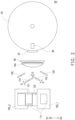
- FIG. 2 and FIG. 3 are schematic views of different viewing angles of the illumination system according to an embodiment of the disclosure.
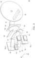
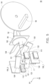
- FIG. 4 is a schematic three-dimensional view of the illumination system of FIG. 2 .
- a light source module 100 shown in FIG. 2 to FIG. 4 may be at least applied to the projection device 10 shown in FIG. 1 , and the following description is made based on the above example.
- lights provided by a first laser array 111 and a second laser array 112 are omitted in FIG. 2 to FIG. 4 to make the image concise.
- the illumination system 50 includes the light source module 100, where the light source module 100 includes a first laser array 111, a second laser array 112, a first reflective element 121, a second reflective element 122, a third reflective element 123, a fourth reflective element 124, a fifth reflective element 125, a sixth reflective element 126, a first light splitting element 131, a second light splitting element 132 and an optical lens element 140.
- the second laser array 112 and the first laser array 111 are respectively located on two opposite sides of a central axis C of the optical lens element 140.
- the first reflective element 121, the second reflective element 122, the third reflective element 123 and the fourth reflective element 124 are located between the first laser array 111 and the second laser array 112, while the fifth reflective element 125, the six reflective elements 126, the first light splitting element 131 and the second light splitting element 132 are located between the first reflective element 121 to the fourth reflective element 124 and the optical lens element 140.
- the first laser array 111 and the second laser array 112 are disposed in a direction parallel to a first direction D1
- the first reflective element 121 to the fourth reflective element 124 are disposed in a direction parallel to a second direction D2
- the orthographic projection of the first reflective element 121 overlaps the orthographic projection of the third reflective element 123 on a reference plane perpendicular to the second direction D2
- the orthographic projection of the second reflective element 122 overlaps the orthographic projection of the fourth reflective element 124 on a reference plane perpendicular to the second direction D2
- the orthographic projections of the first reflective element 121 to the fourth reflective element 124 on a reference plane perpendicular to the central axis C of the optical lens element 140 do not overlap with each other
- the fifth reflective element 125, the sixth reflective element 126, the first light splitting element 131 and the second light splitting element 132 are disposed in the direction parallel to the second direction D2, where the second direction D2 is perpendicular to the first direction D1.
- each of the first laser array 111 and the second laser array 112 has multiple red laser diodes, multiple blue laser diodes, and multiple green laser diodes.
- the multiple red laser diodes are configured to provide multiple red laser light beams.
- the multiple blue laser diodes are configured to provide multiple blue laser light beams.
- the multiple green laser diodes are configured to provide multiple green laser light beams.
- FIG. 5 is a schematic three-dimensional view of the illumination system of FIG. 4 when activating blue light.
- FIG. 6 is a schematic three-dimensional view of the illumination system of FIG. 4 when activating red light.
- the first laser array 111 provides a first light L1 and a second light L2 along the direction parallel to the first direction D1
- the second laser array 112 provides a third light L3 and a fourth light L4 along the direction parallel to the first direction D1.
- Each of the first light L1, the second light L2, the third light L3 and the fourth light L4 may be understood to include multiple laser light beams.
- the first light L1 is, for example, green light or blue light
- the second light L2 is, for example, red light
- the first light L1 may also be, for example, red light
- the second light L2 may also be, for example, green light or blue light, which is not limited by the disclosure.
- the third light L3 is, for example, green light or blue light
- the fourth light L4 is, for example, red light
- the third light L3 may also be, for example, red light
- the fourth light L4 may also be, for example, green light or blue light, which is not limited by the disclosure.
- a position of laser diodes used for providing the first light L1 and a position of laser diodes used for providing the second light L2 are different in the second direction D2, while in the second laser array 112, a position of laser diodes used for providing the third light L3 and a position of laser diodes used for providing the fourth light L4 are different in the second direction D2.
- the orthographic projections of the laser diodes used to provide the first light L1 and the laser diodes used to provide the second light L2 on a reference plane perpendicular to the second direction D2 are overlapped from each other.
- the orthographic projections of the laser diodes used to provide the third light L3 and the laser diodes used to provide the fourth light L4 on the reference plane are overlapped from each other.
- the orthographic projections of the laser diodes in the first laser array 111 used to provide the first light L1, the laser diodes in the first laser array 111 used to provide the second light L2, the laser diodes in the second laser array 112 used to provide the third light L3, and the laser diodes in the second laser array 112 used to provide the fourth light L4 on the reference plane perpendicular to the first direction D1 are staggered from each other.
- a wavelength of the first light L1 is the same as a wavelength of the third light L3, and a wavelength of the second light L2 is the same as a wavelength of the fourth light L4.
- each of the first laser array 111 and the second laser array 112 packages multiple laser diodes, for example, the first laser array 110 and the second laser array 120 package the same laser diodes.
- the first light splitting element 131 and the second light splitting element 132 respectively allow the first light L1 and the third light L3 to pass through, and reflect the second light L2 and the fourth light L4.
- the first light splitting element 131 and the second light splitting element 132 are, for example, dichroic mirrors with red reflect (DNM).
- the first light L1 is sequentially transmitted from the first laser array 111 to the first reflective element 121, the first light splitting element 131 and the optical lens element 140.
- the first laser array 111 provides the first light L1 to the first reflective element 121
- the first reflective element 121 reflects the first light L1 from the first laser array 111 and transmits the same to the first light splitting element 131
- the first light splitting element 131 allows the first light L1 from the first reflective element 121 to pass through for transmitting to the optical lens element 140.
- the first light L1 forms a plurality of first light spots P1 on a light incident surface S of the optical lens element 140 (as shown in FIG. 8A ).
- the second light L2 is sequentially transmitted from the first laser array 111 to the second reflective element 122, the fifth reflective element 125, the second light splitting element 132 and the optical lens element 140.
- the first laser array 111 provides the second light L2 to the second reflective element 122
- the second reflective element 122 reflects the second light L2 from the first laser array 111 and transmits the same to the fifth reflective element 125
- the fifth reflective element 125 reflects the second light L2 from the second reflective element 122 and transmits the same to the second light splitting element 132
- the second light splitting element 132 reflects the second light L2 from the fifth reflective element 125 for transmitting to the optical lens element 140.
- the second light L2 forms a plurality of second light spots P2 on the light incident surface S of the optical lens element 140 (as shown in FIG. 8B ).
- the third light L3 is sequentially transmitted from the second laser array 112 to the third reflective element 123, the second light splitting element 132 and the optical lens element 140.
- the second laser array 112 provides the third light L3 to the third reflective element 123
- the third reflective element 123 reflects the third light L3 from the second laser array 112 and transmits the same to the second light splitting element 132
- the second light splitting element 132 allows the third light L3 from the third reflective element 123 to pass through for transmitting to the optical lens element 140.
- the third light L3 forms a plurality of third light spots P3 on the light incident surface S of the optical lens element 140 (as shown in FIG. 8A ).
- the fourth light L4 is sequentially transmitted from the second laser array 112 to the fourth reflective element 124, the sixth reflective element 126, the first light splitting element 131 and the optical lens element 140.
- the second laser array 112 provides the fourth light L4 to the fourth reflective element 124
- the fourth reflective element 124 reflects the fourth light L4 from the second laser array 112 and transmits the same to the sixth reflective element 126
- the sixth reflective element 126 reflects the fourth light L4 from the fourth reflective element 124 and transmits the same to the first light splitting element 131
- the first light splitting element 131 reflects the fourth light L4 from the sixth reflective element 126 and transmits the same to the optical lens element 140.
- the fourth light L4 forms a plurality of fourth light spots P4 on the light incident surface S of the optical lens element 140 (as shown in FIG. 8B ).
- orthogonal projections of the first light splitting element 131 and the second light splitting element 132 on the optical lens element 140 are at least partially overlapped. That is, the orthographic projection of the first light splitting element 131 partially overlaps the orthographic projection of the the second light splitting element 132 on a reference plane perpendicular to the central axis C of the optical lens element 140, and the two orthographic projections have an overlap length on the second direction D2.
- the two orthographic projections of the first light splitting element 131 and the second light splitting element 132 on a reference plane perpendicular to the central axis C of the optical lens element 140 may partially overlap, and the two orthographic projections have an overlapping length in the second direction D2.
- the orthographic projections of the fifth reflective element 125 and the sixth reflective element 126 on a reference plane perpendicular to the central axis C of the optical lens element 140 do not overlap with each other.
- the first light L1 to the fourth light L4 may be guided to the optical lens element 140 by the first reflective element 121 to the sixth reflective element 126, the first light splitting element 131 and the second light splitting element 132, and the multiple light spots formed by the first light L1 to the fourth light L4 on the light incident surface S of the optical lens element 140 may be uniformized, thereby improving the color uniformity, and saving the configuration of light combining elements and light expanders made of thick glass, so as to reduce volume and cost.
- FIG. 7 is a schematic three-dimensional view of the illumination system in FIG. 4 when activating green light.
- the first laser array 111 may also provide a fifth light L5 along the direction parallel to the first direction D1
- the second laser array 112 may also provide a sixth light L6 along the direction parallel to the first direction D1.
- One of the first reflective element 121 and the second reflective element 122 reflects the fifth light L5 from the first laser array 111
- one of the third reflective element 123 and the fourth reflective element 124 reflects the six light L6 from the second laser array 112.
- a wavelength of the fifth light L5 is the same as a wavelength of the sixth light L6.
- the first light L1 provided by the first laser array 111 is blue light
- the second light L2 is red light
- the fifth light L5 is green light
- the third light L3 provided by the second laser array 112 is blue light
- the fourth light L4 is red light
- the sixth light L6 is green light.
- Each of the fifth light L5 and the sixth light L6 may also be understood to include multiple laser light beams.
- the blue laser diodes and green laser diodes are disposed in one row of the first laser array 111 and the second laser array 112, and the red laser diodes are disposed in another row of the first laser array 111 and the second laser array 112 to balance the light intensity of the red, blue, and green lights. Therefore, the first reflective element 121 is disposed on a transmission path of the first light L1 and the fifth light L5, the second reflective element 122 is disposed on a transmission path of the second light L2, the third reflective element 123 is disposed on a transmission path of the third light L3 and the sixth light L6, and the fourth reflective element 124 is disposed on a transmission path of the fourth light L4.
- the first laser array 111 and the second laser array 112 respectively have four red laser diodes, three green laser diodes and two blue laser diodes, but the disclosure is not limited thereto. That is, the number of the red laser diodes, blue laser diodes and green laser diodes can be greater, for example, the number of red laser diodes is five.
- the light source module 100 further includes two polarizing elements 150_1 and 150_2 respectively disposed on the transmission paths of the lights provided by the first laser array 111 and the second laser array 112.
- the polarizing element 150_1 is disposed on the transmission path of the red light in the first laser array 111, and the polarizing element 150_2 is disposed on the transmission path of the red light in the second laser array 112 for adjusting polarization states of the red lights provided by the first laser array 111 and the second laser array 112.
- the polarizing element 150_1 may also be disposed on the transmission path of the blue light and green light in the first laser array 111, and the polarizing element 150_2 is disposed on the transmission path of the blue light and green light in the second laser array 112, which are not limited by the disclosure.
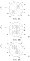
- FIG. 8A to FIG. 8C are schematic diagrams of light spots formed by different light beams on the light incident surface of the optical lens element in the light source module of FIG. 2 .
- the first light L1 of the blue light is transmitted to the the light incident surface S of the optical lens element 140 to form a plurality of first light spots P1.
- the third light L3 of the blue light is transmitted to the the light incident surface S of the optical lens element 140 to form a plurality of third light spots P3, as shown in FIG. 8A .
- the plurality of first light spots P1 and the plurality of third light spots P3 are diagonally symmetrical with respect to a lens center point B of the optical lens element 140.
- the second light L2 of the red light is transmitted to the the light incident surface S of the optical lens element 140 to form a plurality of second light spots P2.
- the fourth light L4 of the red light is transmitted to the the light incident surface S of the optical lens element 140 to form a plurality of fourth light spots P4, as shown in FIG. 8B .
- the plurality of second light spots P2 and the plurality of fourth light spots P4 are arranged in an array with respect to the lens center point B of the optical lens element 140. As shown in FIG.
- the fifth light L5 of the green light is transmitted to the the light incident surface S of the optical lens element 140 to form a plurality of fifth light spots P5.
- the sixth light L6 of the green light is transmitted to the the light incident surface S of the optical lens element 140 to form a plurality of sixth light spots P6, as shown in FIG. 8C .
- the plurality of fifth light spots P5 and the plurality of sixth light spots P6 are diagonally symmetrical with respect to the lens center point B of the optical lens element 140.
- the presentation of the above multiple light spots (multiple first light spots P1, multiple second light spots P2, multiple third light spots P3, multiple fourth light spots P4, multiple fifth light spots P5 and multiple sixth light spots P6) in FIG. 8A, FIG. 8B and FIG. 8C is an example, but the disclosure is not limited thereto.
- the light source module 100 complies with a conditional expression: 1.0 ⁇ (b/a) ⁇ 4.0, where b is a distance M from spot center points F1, F3, F5, and F6 of the plurality of light spots ( FIG. 8A or FIG.
- the light source module 100 may have better luminous efficiency, and the plurality of light spots formed by the blue-green lights on the optical lens element 140 may be symmetrical.
- the light source module 100 complies with a conditional expression: c-d ⁇ e ⁇ c+d, where c is a thickness D of the first light splitting element 131 and the second light splitting element 132 (as shown in FIG. 2 ) divided by a square root of 2, d is 0.1 times the thickness D of the first light splitting element 131 and the second light splitting element 132, and e is a length G (as shown in FIG. 2 ) of the overlapping portion of the orthogonal projections formed by the first light splitting element 131 and the second light splitting element 132 on the light incident surface S of the optical lens element 140 in the direction perpendicular to the first direction D1.
- the distances from the spot center points F1, F2, F3, F4, F5, and F6 of the plurality of light spots to the lens center B of the optical lens element 140 may be further reduced, i.e., the light spots may be concentrated.
- FIG. 9 is a schematic diagram of an optical lens element and a light uniformizing element in an illumination system according to an embodiment of the disclosure.
- a light uniformizing element 56 of the illumination system 50 is disposed on a transmission path of the lights (i.e., the first light L1 to the sixth light L6) from the optical lens element 140, and a light receiving surface of the light uniformizing element 56 is a rectangle with long sides and short sides.
- the light source module 100 complies with a conditional expression: 1.4 ⁇ f *tan( ⁇ )/h ⁇ 3.7, where f is a length H1 of the light uniformizing element 56 in the direction of an optical axis I, ⁇ is an included angle between the maximum length from the optical lens element 140 to the light uniformizing element 56 and the minimum length from the optical lens element 140 to the light uniformizing element 56, and h is a length H2 of the long side of the light uniformizing element 56 in the direction perpendicular to the optical axis I.
- f is a length H1 of the light uniformizing element 56 in the direction of an optical axis I
- ⁇ is an included angle between the maximum length from the optical lens element 140 to the light uniformizing element 56 and the minimum length from the optical lens element 140 to the light uniformizing element 56
- h is a length H2 of the long side of the light uniformizing element 56 in the direction perpendicular to the optical axis I.
- the embodiments of the disclosure have at least one of the following advantages or effects.
- the first laser array provides the first light and the second light along the direction parallel to the first direction
- the second laser array provides the third light and the fourth light along the direction parallel to the first direction
- the first reflective element to the fourth reflective element are located between the first laser array and the second laser array to reflect the first light to the fourth light to the fifth reflective element, the sixth reflective element, the first light splitting element and the second light splitting element.
- first light to the fourth light may be guided to the optical lens element by the first reflective element to the sixth reflective element, the first light splitting element and the second light splitting element, and the multiple light spots formed by the first light to the fourth light on the light incident surface of the optical lens element may be uniformized, thereby improving color uniformity, and saving the configuration of light combining elements and light expanders made of thick glass, so as to reduce volume and cost.
- first direction and “second direction” described in all the embodiments of the present disclosure refer to D1 and D2 as shown in the figure, that is, “first direction” is the direction in which the "D1" line extends, “second direction” is the direction in which the "D2" line extends.
- the term "the disclosure” does not necessarily limit the claim scope to a specific embodiment, and the reference to particularly preferred exemplary embodiments of the disclosure does not imply a limitation on the disclosure, and no such limitation is to be inferred.
- the disclosure is limited only by the spirit and scope of the appended claims.
- the abstract of the disclosure is provided to comply with the rules requiring an abstract, which will allow a searcher to quickly ascertain the subject matter of the technical disclosure of any patent issued from this disclosure. It is submitted with the understanding that it will not be used to interpret or limit the scope or meaning of the claims. Any advantages and benefits described may not apply to all embodiments of the disclosure. It should be appreciated that variations may be made in the embodiments described by persons skilled in the art without departing from the scope of the disclosure as defined by the following claims. Moreover, no element and component in the present disclosure is intended to be dedicated to the public regardless of whether the element or component is explicitly recited in the following claims.
Landscapes
- Physics & Mathematics (AREA)
- General Physics & Mathematics (AREA)
- Optics & Photonics (AREA)
- Projection Apparatus (AREA)
- Non-Portable Lighting Devices Or Systems Thereof (AREA)
Abstract
Description
- The disclosure relates to an optical module and an electronic device, and particularly relates to a light source module and a projection device.
- Projection device is a display device for producing large-scale images, and has been continuously developed along with evolution and innovation of technology. An imaging principle of the projection device is to convert an illumination light generated by an illumination system into an image light through a light valve, and then project the image light to a projection target (such as a screen or a wall) through a projection lens to form a projection image. In addition, along with requirements of the market on brightness, color saturation, service life, non-toxic and environmental protection of the projection device, the illumination system has also evolved from ultra-high-performance lamps (UHP lamps), light-emitting diodes (LEDs) to today's most advanced laser diode (LD) light source, and even all-in-one laser diode package light source is developed.
- In order to improve color uniformity and reduce an overall volume, in an optical path design of the system, blue light and green light are usually first combined before entering an optical engine system. However, in a current framework, thick glass optical elements are mostly used for combining light, and the cost of such optical elements is high. In addition, in order to match with red light, the blue-green light needs to be expanded after light combination, but this method will increase additional cost and volume.
- The information disclosed in this Background section is only for enhancement of understanding of the background of the described technology and therefore it may contain information that does not form the prior art that is already known to a person of ordinary skill in the art. Further, the information disclosed in the Background section does not mean that one or more problems to be resolved by one or more embodiments of the disclosure was acknowledged by a person of ordinary skill in the art.
- The disclosure is directed to a light source module and a projection device, which are adapted to uniformize a plurality of light spots formed by light beams on a light incident surface of an optical lens element, thereby improving color uniformity, and reducing volume and cost.
- Additional aspects and advantages of the disclosure will be set forth in the description of the techniques disclosed in the disclosure.
- The object is solved by the features of the independent claims. Preferred embodiments are given in the dependent claims.
- In order to achieve one or a portion of or all of the objects or other objects, an embodiment of the disclosure provides a light source module including a first laser array, a second laser array, a first reflective element, a second reflective element, a third reflective element, a fourth reflective element, a fifth reflective element, a sixth reflective element, a first light splitting element, a second light splitting element and an optical lens element. Where, the first laser array provides a first light and a second light along a direction parallel to a first direction. The second laser array provides a third light and a fourth light along the direction parallel to the first direction. The first light is sequentially transmitted from the first laser array to the first reflective element, the first light splitting element and the optical lens element. The second light is sequentially transmitted from the first laser array to the second reflective element, the fifth reflective element, the second light splitting element and the optical lens element. The third light is sequentially transmitted from the second laser array to the third reflective element, the second light splitting element and the optical lens element. The fourth light is sequentially transmitted from the second laser array to the fourth reflective element, the sixth reflective element, the first light splitting element and the optical lens element. The first light splitting element is configured to reflect the fourth light from the sixth reflective element and allow the first light from the first reflective element to pass through to the optical lens element. The second light splitting element is configured to reflect the second light from the fifth reflective element and allow the third light from the third reflective element to pass through to the optical lens element. Wherein, orthogonal projections of the first light splitting element and the second light splitting element on the optical lens element are at least partially overlapped.
- In order to achieve one or a portion of or all of the objects or other objects, an embodiment of the disclosure provides a projection device including an illumination system, at least one light valve and a projection lens. Where, the illumination system is configured to provide an illumination light. The light source module includes a first laser array, a second laser array, a first reflective element, a second reflective element, a third reflective element, a fourth reflective element, a fifth reflective element, a sixth reflective element, a first light splitting element, a second light splitting element and an optical lens element. Where, the first laser array provides a first light and a second light along a direction parallel to a first direction. The second laser array provides a third light and a fourth light along the direction parallel to the first direction. The first light is sequentially transmitted from the first laser array to the first reflective element, the first light splitting element and the optical lens element. The second light is sequentially transmitted from the first laser array to the second reflective element, the fifth reflective element, the second light splitting element and the optical lens element. The third light is sequentially transmitted from the second laser array to the third reflective element, the second light splitting element and the optical lens element. The fourth light is sequentially transmitted from the second laser array to the fourth reflective element, the sixth reflective element, the first light splitting element and the optical lens element. The first light splitting element is configured to reflect the fourth light from the sixth reflective element and allow the first light from the first reflective element to pass through to the optical lens element. The second light splitting element is configured to reflect the second light from the fifth reflective element and allow the third light from the third reflective element to pass through to the optical lens element. Wherein, orthogonal projections of the first light splitting element and the second light splitting element on the optical lens element are at least partially overlapped. The at least one light valve is disposed on a transmission path of the illumination light for converting the illumination light into an image light. The projection lens is disposed on a transmission path of the image light, and is configured to project the image light out of the projection device.
- In one or more embodiments, the first laser array and the second laser array may be arranged in the direction parallel to the first direction.
- In one or more embodiments, the first reflective element to the fourth reflective element may be arranged in a direction parallel to a second direction.
- In one or more embodiments, the fifth reflective element, the sixth reflective element, the first light splitting element, and the second light splitting element may be arranged in the direction parallel to the second direction.
- In one or more embodiments, the second direction may be perpendicular to the first direction.
- In one or more embodiments, the first reflective element to the fourth reflective element may be located between the first laser array and the second laser array.
- In one or more embodiments, the fifth reflective element, the sixth reflective element, the first light splitting element and the second light splitting element may be located between the first reflective element to the fourth reflective element and the optical lens element.
- In one or more embodiments, the second laser array and the first laser array may be respectively located on two opposite sides of a central axis of the optical lens element.
- In one or more embodiments, a wavelength of the first light may be the same as a wavelength of the third light.
- In one or more embodiments, a wavelength of the second light may be the same as a wavelength of the fourth light.
- In one or more embodiments, a plurality of first light spots formed by the first light on a light incident surface of the optical lens element and a plurality of third light spots formed by the third light on the light incident surface of the optical lens element may be diagonally symmetrical or arranged in an array with respect to a lens center point of the optical lens element.
- In one or more embodiments, a plurality of second light spots formed by the second light on the light incident surface of the optical lens element and a plurality of fourth light spots formed by the fourth light on the light incident surface of the optical lens element may be diagonally symmetrical or arranged in an array with respect to the lens center point of the optical lens element.
- In one or more embodiments, the lens center point may be located on the central axis of the optical lens element.
- In one or more embodiments, the first laser array may further provide a fifth light along the direction parallel to the first direction.
- In one or more embodiments, the second laser array may further provide a sixth light along the direction parallel to the first direction.
- In one or more embodiments, one of the first reflective element and the second reflective element may reflect the fifth light from the first laser array.
- In one or more embodiments, one of the third reflective element and the fourth reflective element may reflect the sixth light from the second laser array.
- In one or more embodiments, a wavelength of the fifth light may be the same as a wavelength of the sixth light.
- In one or more embodiments, the light source module may comply with a conditional expression: 1.0<(b/a)<4.0, wherein 'b' is a distance from a spot center point of a plurality of light spots formed by the first light or the third light on the optical lens element to a lens center point of the optical lens element in a direction perpendicular to the first direction, and 'a' is a distance from the spot center point of the plurality of light spots formed by the first light or the third light on the optical lens element to the lens center point of the optical lens element in the first direction.
- In one or more embodiments, the light source module may comply with a conditional expression: c-d<e<c+d, wherein 'c' is a thickness of the first light splitting element and the second light splitting element divided by a square root of 2, 'd' is 0.1 times the thickness of the first light splitting element and the second light splitting element, and 'e' is a length of an overlapping portion of orthogonal projections formed by the first light splitting element and the second light splitting element on a light incident surface of the optical lens element in a direction perpendicular to the first direction.
- In one or more embodiments, the illumination system may further comprise a light uniformizing element disposed on a transmission path of the first light to the fourth light from the optical lens element.
- In one or more embodiments, the light source module may comply with a conditional expression: 1.4≦f *tan( θ )/h≦3.7, wherein f is a length of the light uniformizing element in a direction of an optical axis, θ is an included angle between the maximum length from the optical lens element to the light uniformizing element and the minimum length from the optical lens element to the light uniformizing element, and h is a length of a long side of the light uniformizing element in a direction perpendicular to the optical axis.
- Based on the above description, the embodiments of the disclosure have at least one of the following advantages or effects. In the light source module and the projection device of the disclosure, the first laser array provides the first light and the second light along the direction parallel to the first direction, the second laser array provides the third light and the fourth light along the direction parallel to the first direction, and the first reflective element to the fourth reflective element are located between the first laser array and the second laser array to reflect the first light to the fourth light to the fifth reflective element, the sixth reflective element, the first light splitting element and the second light splitting element. In this way, the first light to the fourth light may be guided to the optical lens element by the first reflective element to the sixth reflective element, the first light splitting element and the second light splitting element, and the multiple light spots formed by the first light to the fourth light on a light incident surface of the optical lens element may be uniformized, thereby improving color uniformity, and saving the configuration of light combining elements and light expanders made of thick glass, so as to reduce volume and cost.
- Other objectives, features and advantages of the disclosure will be further understood from the further technological features disclosed by the embodiments of the disclosure wherein there are shown and described preferred embodiments of this disclosure, simply by way of illustration of modes best suited to carry out the disclosure.
- The accompanying drawings are included to provide a further understanding of the disclosure, and are incorporated in and constitute a part of this specification. The drawings illustrate embodiments of the disclosure and, together with the description, serve to explain the principles of the disclosure.
-
FIG. 1 is a schematic diagram of a projection device according to an embodiment of the disclosure. -
FIG. 2 andFIG. 3 are schematic views of different viewing angles of an illumination system according to an embodiment of the disclosure. -
FIG. 4 is a schematic three-dimensional view of the illumination system ofFIG. 2 . -
FIG. 5 is a schematic three-dimensional view of the illumination system ofFIG. 4 when activating blue light. -
FIG. 6 is a schematic three-dimensional view of the illumination system ofFIG. 4 when activating red light. -
FIG. 7 is a schematic three-dimensional view of the illumination system inFIG. 4 when activating green light. -
FIG. 8A to FIG. 8C are schematic diagrams of light spots formed by different light beams on a light incident surface of an optical lens element in a light source module ofFIG. 2 . -
FIG. 9 is a schematic diagram of an optical lens element and a light uniformizing element in an illumination system according to an embodiment of the disclosure. - In the following detailed description of the preferred embodiments, reference is made to the accompanying drawings which form a part hereof, and in which are shown by way of illustration specific embodiments in which the disclosure may be practiced. In this regard, directional terminology, such as "top," "bottom," "front," "back," etc., is used with reference to the orientation of the Figure(s) being described. The components of the disclosure can be positioned in a number of different orientations. As such, the directional terminology is used for purposes of illustration and is in no way limiting. On the other hand, the drawings are only schematic and the sizes of components may be exaggerated for clarity. It is to be understood that other embodiments may be utilized and structural changes may be made without departing from the scope of the disclosure. Also, it is to be understood that the phraseology and terminology used herein are for the purpose of description and should not be regarded as limiting. The use of "including," "comprising," or "having" and variations thereof herein is meant to encompass the items listed thereafter and equivalents thereof as well as additional items. Unless limited otherwise, the terms "connected," "coupled," and "mounted" and variations thereof herein are used broadly and encompass direct and indirect connections, couplings, and mountings. Similarly, the terms "facing," "faces" and variations thereof herein are used broadly and encompass direct and indirect facing, and "adjacent to" and variations thereof herein are used broadly and encompass directly and indirectly "adjacent to". Therefore, the description of "A" component facing "B" component herein may contain the situations that "A" component directly faces "B" component or one or more additional components are between "A" component and "B" component. Also, the description of "A" component "adjacent to" "B" component herein may contain the situations that "A" component is directly "adjacent to" "B" component or one or more additional components are between "A" component and "B" component. Accordingly, the drawings and descriptions will be regarded as illustrative in nature and not as restrictive.
-
FIG. 1 is a schematic diagram of a projection device according to an embodiment of the disclosure. Referring toFIG. 1 , the embodiment provides aprojection device 10 including anillumination system 50, at least onelight valve 60 and aprojection lens 70. Where, theillumination system 50 is configured to provide an illumination light LB. The at least onelight valve 60 is disposed on a transmission path of the illumination light LB for converting the illumination light LB into an image light LI. Theprojection lens 70 is disposed on a transmission path of the image light LI, and is configured to project the image light LI out of theprojection device 10 to a projection target (not shown), such as a screen or a wall. - The
illumination system 50 is configured to provide the illumination light LB. For example, in the embodiment, theillumination system 50 is composed of a plurality of light-emitting elements, areflective element 52,diffusion elements 54/58, alight uniformizing element 56 and/or a plurality of light guide elements, and is used for providing lights of different wavelengths for subsequently forming the image light LI. Where, the plurality of light-emitting elements are, for example, laser diodes (LDs); thediffusion element 54 is, for example, a diffuser wheel, and thediffusion element 58 is, for example, a static diffuser. In the embodiment, thediffusion element 54 and thediffusion element 58 may have different hazes to make color more uniform, but the disclosure is not limited thereto; thelight uniformizing element 56 is, for example, an integrating rod, which may be made of reflective mirrors, and, for example, adopt multiple reflections to enhance laser light uniformity; the light guide elements are, for example, dichroic mirrors or reflectors. However, the disclosure does not limit the type or form of theillumination system 50 and the various components it contains in theprojection device 10, and its detailed structure and implementation method may be provided with sufficient guidance, suggestions, and implementation instructions based on subsequent explanations and common knowledge in the technical field. - The
light valve 60 is, for example, a reflective light modulator such as a liquid crystal on silicon panel (LCoS panel) or a digital micro-mirror device (DMD). In some embodiments, thelight valve 60 may also be a transmissive optical modulator such as a transparent liquid crystal panel, an electro-optical modulator, a magneto-optic modulator, an acousto-optic modulator (AOM), etc. The disclosure does not limit the form and type of thelight valve 60. Detailed steps and implementation of the method of converting the illumination light LB into the image light LI by thelight valve 60 may be provided with sufficient guidance, suggestions, and implementation instructions based on general knowledge in the related technical field, which will not be repeated. In the embodiment, the number of thelight valve 60 is one, for example, theprojection device 10 using a single digital micro-mirror device, but there may be multiple light valves in other embodiments, and the disclosure is not limited thereto. - The
projection lens 70 includes, for example, a combination of one or more optical lens elementes with refractive power, for example, various combinations of non-planar lenses such as biconcave lenses, biconvex lenses, concavo-convex lenses, convexo-concave lenses, plano-convex lenses, plano-concave lenses, etc. In an embodiment, theprojection lens 70 may also include a planar optical lens element, which projects the image light LI from thelight valve 60 onto the projection target in a reflective manner. The disclosure does not limit the form and type of theprojection lens 70. -
FIG. 2 andFIG. 3 are schematic views of different viewing angles of the illumination system according to an embodiment of the disclosure.FIG. 4 is a schematic three-dimensional view of the illumination system ofFIG. 2 . Alight source module 100 shown inFIG. 2 to FIG. 4 may be at least applied to theprojection device 10 shown inFIG. 1 , and the following description is made based on the above example. Referring toFIG. 2 to FIG. 4 , lights provided by afirst laser array 111 and asecond laser array 112 are omitted inFIG. 2 to FIG. 4 to make the image concise. Theillumination system 50 includes thelight source module 100, where thelight source module 100 includes afirst laser array 111, asecond laser array 112, a firstreflective element 121, a secondreflective element 122, a thirdreflective element 123, a fourthreflective element 124, a fifthreflective element 125, a sixthreflective element 126, a firstlight splitting element 131, a secondlight splitting element 132 and anoptical lens element 140. Where, thesecond laser array 112 and thefirst laser array 111 are respectively located on two opposite sides of a central axis C of theoptical lens element 140. Specifically, the firstreflective element 121, the secondreflective element 122, the thirdreflective element 123 and the fourthreflective element 124 are located between thefirst laser array 111 and thesecond laser array 112, while the fifthreflective element 125, the sixreflective elements 126, the firstlight splitting element 131 and the secondlight splitting element 132 are located between the firstreflective element 121 to the fourthreflective element 124 and theoptical lens element 140. In the embodiment, thefirst laser array 111 and thesecond laser array 112 are disposed in a direction parallel to a first direction D1, the firstreflective element 121 to the fourthreflective element 124 are disposed in a direction parallel to a second direction D2, the orthographic projection of the firstreflective element 121 overlaps the orthographic projection of the thirdreflective element 123 on a reference plane perpendicular to the second direction D2, the orthographic projection of the secondreflective element 122 overlaps the orthographic projection of the fourthreflective element 124 on a reference plane perpendicular to the second direction D2, the orthographic projections of the firstreflective element 121 to the fourthreflective element 124 on a reference plane perpendicular to the central axis C of theoptical lens element 140 do not overlap with each other, and the fifthreflective element 125, the sixthreflective element 126, the firstlight splitting element 131 and the secondlight splitting element 132 are disposed in the direction parallel to the second direction D2, where the second direction D2 is perpendicular to the first direction D1. - In this embodiment, each of the
first laser array 111 and thesecond laser array 112 has multiple red laser diodes, multiple blue laser diodes, and multiple green laser diodes. The multiple red laser diodes are configured to provide multiple red laser light beams. The multiple blue laser diodes are configured to provide multiple blue laser light beams. The multiple green laser diodes are configured to provide multiple green laser light beams. -
FIG. 5 is a schematic three-dimensional view of the illumination system ofFIG. 4 when activating blue light.FIG. 6 is a schematic three-dimensional view of the illumination system ofFIG. 4 when activating red light. Referring toFIG. 5 andFIG. 6 at the same time, in detail, thefirst laser array 111 provides a first light L1 and a second light L2 along the direction parallel to the first direction D1, and thesecond laser array 112 provides a third light L3 and a fourth light L4 along the direction parallel to the first direction D1. Each of the first light L1, the second light L2, the third light L3 and the fourth light L4 may be understood to include multiple laser light beams. In the embodiment, the first light L1 is, for example, green light or blue light, and the second light L2 is, for example, red light, but the first light L1 may also be, for example, red light, and the second light L2 may also be, for example, green light or blue light, which is not limited by the disclosure. The third light L3 is, for example, green light or blue light, and the fourth light L4 is, for example, red light, but the third light L3 may also be, for example, red light, and the fourth light L4 may also be, for example, green light or blue light, which is not limited by the disclosure. In thefirst laser array 111, a position of laser diodes used for providing the first light L1 and a position of laser diodes used for providing the second light L2 are different in the second direction D2, while in thesecond laser array 112, a position of laser diodes used for providing the third light L3 and a position of laser diodes used for providing the fourth light L4 are different in the second direction D2. In thefirst laser array 111, the orthographic projections of the laser diodes used to provide the first light L1 and the laser diodes used to provide the second light L2 on a reference plane perpendicular to the second direction D2 are overlapped from each other. In thesecond laser array 112, the orthographic projections of the laser diodes used to provide the third light L3 and the laser diodes used to provide the fourth light L4 on the reference plane are overlapped from each other. The orthographic projections of the laser diodes in thefirst laser array 111 used to provide the first light L1, the laser diodes in thefirst laser array 111 used to provide the second light L2, the laser diodes in thesecond laser array 112 used to provide the third light L3, and the laser diodes in thesecond laser array 112 used to provide the fourth light L4 on the reference plane perpendicular to the first direction D1 are staggered from each other. In the embodiment, a wavelength of the first light L1 is the same as a wavelength of the third light L3, and a wavelength of the second light L2 is the same as a wavelength of the fourth light L4. In other words, each of thefirst laser array 111 and thesecond laser array 112 packages multiple laser diodes, for example, the first laser array 110 and the second laser array 120 package the same laser diodes. In the embodiment, the firstlight splitting element 131 and the secondlight splitting element 132 respectively allow the first light L1 and the third light L3 to pass through, and reflect the second light L2 and the fourth light L4. Namely, the firstlight splitting element 131 and the secondlight splitting element 132 are, for example, dichroic mirrors with red reflect (DNM). - In an optical path structure, the first light L1 is sequentially transmitted from the
first laser array 111 to the firstreflective element 121, the firstlight splitting element 131 and theoptical lens element 140. In other words, thefirst laser array 111 provides the first light L1 to the firstreflective element 121, and the firstreflective element 121 reflects the first light L1 from thefirst laser array 111 and transmits the same to the firstlight splitting element 131, and the firstlight splitting element 131 allows the first light L1 from the firstreflective element 121 to pass through for transmitting to theoptical lens element 140. Finally, the first light L1 forms a plurality of first light spots P1 on a light incident surface S of the optical lens element 140 (as shown inFIG. 8A ). - The second light L2 is sequentially transmitted from the
first laser array 111 to the secondreflective element 122, the fifthreflective element 125, the secondlight splitting element 132 and theoptical lens element 140. In other words, thefirst laser array 111 provides the second light L2 to the secondreflective element 122, the secondreflective element 122 reflects the second light L2 from thefirst laser array 111 and transmits the same to the fifthreflective element 125, and the fifthreflective element 125 reflects the second light L2 from the secondreflective element 122 and transmits the same to the secondlight splitting element 132, and the secondlight splitting element 132 reflects the second light L2 from the fifthreflective element 125 for transmitting to theoptical lens element 140. Finally, the second light L2 forms a plurality of second light spots P2 on the light incident surface S of the optical lens element 140 (as shown inFIG. 8B ). - The third light L3 is sequentially transmitted from the
second laser array 112 to the thirdreflective element 123, the secondlight splitting element 132 and theoptical lens element 140. In other words, thesecond laser array 112 provides the third light L3 to the thirdreflective element 123, the thirdreflective element 123 reflects the third light L3 from thesecond laser array 112 and transmits the same to the secondlight splitting element 132, and the secondlight splitting element 132 allows the third light L3 from the thirdreflective element 123 to pass through for transmitting to theoptical lens element 140. Finally, the third light L3 forms a plurality of third light spots P3 on the light incident surface S of the optical lens element 140 (as shown inFIG. 8A ). - The fourth light L4 is sequentially transmitted from the
second laser array 112 to the fourthreflective element 124, the sixthreflective element 126, the firstlight splitting element 131 and theoptical lens element 140. In other words, thesecond laser array 112 provides the fourth light L4 to the fourthreflective element 124, the fourthreflective element 124 reflects the fourth light L4 from thesecond laser array 112 and transmits the same to the sixthreflective element 126, the sixthreflective element 126 reflects the fourth light L4 from the fourthreflective element 124 and transmits the same to the firstlight splitting element 131, and the firstlight splitting element 131 reflects the fourth light L4 from the sixthreflective element 126 and transmits the same to theoptical lens element 140. Finally, the fourth light L4 forms a plurality of fourth light spots P4 on the light incident surface S of the optical lens element 140 (as shown inFIG. 8B ). - It should be noted that orthogonal projections of the first
light splitting element 131 and the secondlight splitting element 132 on theoptical lens element 140 are at least partially overlapped. That is, the orthographic projection of the firstlight splitting element 131 partially overlaps the orthographic projection of the the secondlight splitting element 132 on a reference plane perpendicular to the central axis C of theoptical lens element 140, and the two orthographic projections have an overlap length on the second direction D2. For example, in the embodiment, by configuring a distance between the secondlight splitting element 132 and theoptical lens element 140 to be smaller than a distance between the firstlight splitting element 131 and theoptical lens element 140, the two orthographic projections of the firstlight splitting element 131 and the secondlight splitting element 132 on a reference plane perpendicular to the central axis C of theoptical lens element 140 may partially overlap, and the two orthographic projections have an overlapping length in the second direction D2. In addition, the orthographic projections of the fifthreflective element 125 and the sixthreflective element 126 on a reference plane perpendicular to the central axis C of theoptical lens element 140 do not overlap with each other. In this way, the first light L1 to the fourth light L4 may be guided to theoptical lens element 140 by the firstreflective element 121 to the sixthreflective element 126, the firstlight splitting element 131 and the secondlight splitting element 132, and the multiple light spots formed by the first light L1 to the fourth light L4 on the light incident surface S of theoptical lens element 140 may be uniformized, thereby improving the color uniformity, and saving the configuration of light combining elements and light expanders made of thick glass, so as to reduce volume and cost. -
FIG. 7 is a schematic three-dimensional view of the illumination system inFIG. 4 when activating green light. In the embodiment, thefirst laser array 111 may also provide a fifth light L5 along the direction parallel to the first direction D1, and thesecond laser array 112 may also provide a sixth light L6 along the direction parallel to the first direction D1. One of the firstreflective element 121 and the secondreflective element 122 reflects the fifth light L5 from thefirst laser array 111, and one of the thirdreflective element 123 and the fourthreflective element 124 reflects the six light L6 from thesecond laser array 112. A wavelength of the fifth light L5 is the same as a wavelength of the sixth light L6. For example, in the embodiment, the first light L1 provided by thefirst laser array 111 is blue light, the second light L2 is red light, and the fifth light L5 is green light. The third light L3 provided by thesecond laser array 112 is blue light, the fourth light L4 is red light, and the sixth light L6 is green light. Each of the fifth light L5 and the sixth light L6 may also be understood to include multiple laser light beams. - Therefore, according to intensity characteristics of the red, blue, and green laser lights, the blue laser diodes and green laser diodes are disposed in one row of the
first laser array 111 and thesecond laser array 112, and the red laser diodes are disposed in another row of thefirst laser array 111 and thesecond laser array 112 to balance the light intensity of the red, blue, and green lights. Therefore, the firstreflective element 121 is disposed on a transmission path of the first light L1 and the fifth light L5, the secondreflective element 122 is disposed on a transmission path of the second light L2, the thirdreflective element 123 is disposed on a transmission path of the third light L3 and the sixth light L6, and the fourthreflective element 124 is disposed on a transmission path of the fourth light L4. In the embodiment, thefirst laser array 111 and thesecond laser array 112 respectively have four red laser diodes, three green laser diodes and two blue laser diodes, but the disclosure is not limited thereto. That is, the number of the red laser diodes, blue laser diodes and green laser diodes can be greater, for example, the number of red laser diodes is five. In addition, in the embodiment, thelight source module 100 further includes two polarizing elements 150_1 and 150_2 respectively disposed on the transmission paths of the lights provided by thefirst laser array 111 and thesecond laser array 112. For example, the polarizing element 150_1 is disposed on the transmission path of the red light in thefirst laser array 111, and the polarizing element 150_2 is disposed on the transmission path of the red light in thesecond laser array 112 for adjusting polarization states of the red lights provided by thefirst laser array 111 and thesecond laser array 112. In another embodiment, the polarizing element 150_1 may also be disposed on the transmission path of the blue light and green light in thefirst laser array 111, and the polarizing element 150_2 is disposed on the transmission path of the blue light and green light in thesecond laser array 112, which are not limited by the disclosure. -
FIG. 8A to FIG. 8C are schematic diagrams of light spots formed by different light beams on the light incident surface of the optical lens element in the light source module ofFIG. 2 . Referring toFIG. 2 andFIG. 8A to 8C at the same time. As shown inFIG. 8A , the first light L1 of the blue light is transmitted to the the light incident surface S of theoptical lens element 140 to form a plurality of first light spots P1. The third light L3 of the blue light is transmitted to the the light incident surface S of theoptical lens element 140 to form a plurality of third light spots P3, as shown inFIG. 8A . The plurality of first light spots P1 and the plurality of third light spots P3 are diagonally symmetrical with respect to a lens center point B of theoptical lens element 140. As shown inFIG. 8B , the second light L2 of the red light is transmitted to the the light incident surface S of theoptical lens element 140 to form a plurality of second light spots P2. The fourth light L4 of the red light is transmitted to the the light incident surface S of theoptical lens element 140 to form a plurality of fourth light spots P4, as shown inFIG. 8B . The plurality of second light spots P2 and the plurality of fourth light spots P4 are arranged in an array with respect to the lens center point B of theoptical lens element 140. As shown inFIG. 8C , the fifth light L5 of the green light is transmitted to the the light incident surface S of theoptical lens element 140 to form a plurality of fifth light spots P5. The sixth light L6 of the green light is transmitted to the the light incident surface S of theoptical lens element 140 to form a plurality of sixth light spots P6, as shown inFIG. 8C . The plurality of fifth light spots P5 and the plurality of sixth light spots P6 are diagonally symmetrical with respect to the lens center point B of theoptical lens element 140. The presentation of the above multiple light spots (multiple first light spots P1, multiple second light spots P2, multiple third light spots P3, multiple fourth light spots P4, multiple fifth light spots P5 and multiple sixth light spots P6) inFIG. 8A, FIG. 8B and FIG. 8C is an example, but the disclosure is not limited thereto. - For the diagonally symmetrical light spots, in a preferred embodiment, the
light source module 100 complies with a conditional expression: 1.0<(b/a)<4.0, where b is a distance M from spot center points F1, F3, F5, and F6 of the plurality of light spots (FIG. 8A or FIG. 8C ) formed by the lights (the first light L1 and the third light L3 of the blue light, the fifth light L5 and the sixth light L6 of the green light) on theoptical lens element 140 to the lens center point B of theoptical lens element 140 in the first direction D1, and a is a distance N from the spot center points of the plurality of light spots formed by the lights on theoptical lens element 140 to the lens center point B of theoptical lens element 140 in a direction perpendicular to the first direction D1. In this way, thelight source module 100 may have better luminous efficiency, and the plurality of light spots formed by the blue-green lights on theoptical lens element 140 may be symmetrical. - In addition, in a preferred embodiment, the
light source module 100 complies with a conditional expression: c-d<e<c+d, where c is a thickness D of the firstlight splitting element 131 and the second light splitting element 132 (as shown inFIG. 2 ) divided by a square root of 2, d is 0.1 times the thickness D of the firstlight splitting element 131 and the secondlight splitting element 132, and e is a length G (as shown inFIG. 2 ) of the overlapping portion of the orthogonal projections formed by the firstlight splitting element 131 and the secondlight splitting element 132 on the light incident surface S of theoptical lens element 140 in the direction perpendicular to the first direction D1. In this way, the distances from the spot center points F1, F2, F3, F4, F5, and F6 of the plurality of light spots to the lens center B of theoptical lens element 140 may be further reduced, i.e., the light spots may be concentrated. -
FIG. 9 is a schematic diagram of an optical lens element and a light uniformizing element in an illumination system according to an embodiment of the disclosure. Referring toFIG. 2 andFIG. 9 at the same time, in addition, alight uniformizing element 56 of theillumination system 50 is disposed on a transmission path of the lights (i.e., the first light L1 to the sixth light L6) from theoptical lens element 140, and a light receiving surface of thelight uniformizing element 56 is a rectangle with long sides and short sides. In a preferred embodiment, thelight source module 100 complies with a conditional expression: 1.4 ≦f *tan( θ )/h≦3.7, where f is a length H1 of thelight uniformizing element 56 in the direction of an optical axis I, θ is an included angle between the maximum length from theoptical lens element 140 to thelight uniformizing element 56 and the minimum length from theoptical lens element 140 to thelight uniformizing element 56, and h is a length H2 of the long side of thelight uniformizing element 56 in the direction perpendicular to the optical axis I. In this way, the luminous efficiency and uniformity of theillumination system 50 may be further improved, and the design of ≦3.7 results in a better space utilization rate of thelight uniformizing element 56. - In summary, the embodiments of the disclosure have at least one of the following advantages or effects. In the light source module and the projection device of the disclosure, the first laser array provides the first light and the second light along the direction parallel to the first direction, the second laser array provides the third light and the fourth light along the direction parallel to the first direction, and the first reflective element to the fourth reflective element are located between the first laser array and the second laser array to reflect the first light to the fourth light to the fifth reflective element, the sixth reflective element, the first light splitting element and the second light splitting element. In this way, the first light to the fourth light may be guided to the optical lens element by the first reflective element to the sixth reflective element, the first light splitting element and the second light splitting element, and the multiple light spots formed by the first light to the fourth light on the light incident surface of the optical lens element may be uniformized, thereby improving color uniformity, and saving the configuration of light combining elements and light expanders made of thick glass, so as to reduce volume and cost. In addition, "first direction" and "second direction" described in all the embodiments of the present disclosure refer to D1 and D2 as shown in the figure, that is, "first direction" is the direction in which the "D1" line extends, "second direction" is the direction in which the "D2" line extends.
- The foregoing description of the preferred embodiments of the disclosure has been presented for purposes of illustration and description. It is not intended to be exhaustive or to limit the disclosure to the precise form or to exemplary embodiments disclosed. Accordingly, the foregoing description should be regarded as illustrative rather than restrictive. Obviously, many modifications and variations will be apparent to practitioners skilled in this art. The embodiments are chosen and described in order to best explain the principles of the disclosure and its best mode practical application, thereby to enable persons skilled in the art to understand the disclosure for various embodiments and with various modifications as are suited to the particular use or implementation contemplated. It is intended that the scope of the disclosure be defined by the claims appended hereto and their equivalents in which all terms are meant in their broadest reasonable sense unless otherwise indicated. Therefore, the term "the disclosure" does not necessarily limit the claim scope to a specific embodiment, and the reference to particularly preferred exemplary embodiments of the disclosure does not imply a limitation on the disclosure, and no such limitation is to be inferred. The disclosure is limited only by the spirit and scope of the appended claims. The abstract of the disclosure is provided to comply with the rules requiring an abstract, which will allow a searcher to quickly ascertain the subject matter of the technical disclosure of any patent issued from this disclosure. It is submitted with the understanding that it will not be used to interpret or limit the scope or meaning of the claims. Any advantages and benefits described may not apply to all embodiments of the disclosure. It should be appreciated that variations may be made in the embodiments described by persons skilled in the art without departing from the scope of the disclosure as defined by the following claims. Moreover, no element and component in the present disclosure is intended to be dedicated to the public regardless of whether the element or component is explicitly recited in the following claims.
Claims (15)
- A light source module (100), comprising a first laser array (111), a second laser array (112), a first reflective element (121), a second reflective element (122), a third reflective element (123), a fourth reflective element (124), a fifth reflective element (125), a sixth reflective element (126), a first light splitting element (131), a second light splitting element (132) and an optical lens element (140), wherein:the first laser array (111) provides a first light (L1) and a second light (L2) along a direction parallel to a first direction (D1);the second laser array (112) provides a third light (L3) and a fourth light (L4) along the direction parallel to the first direction (D1);the first light (L1) is sequentially transmitted from the first laser array (111) to the first reflective element (121), the first light splitting element (131) and the optical lens element (140);the second light (L2) is sequentially transmitted from the first laser array (111) to the second reflective element (122), the fifth reflective element (125), the second light splitting element (132) and the optical lens element (140);the third light (L3) is sequentially transmitted from the second laser array (112) to the third reflective element (123), the second light splitting element (132) and the optical lens element (140);the fourth light (L4) is sequentially transmitted from the second laser array (112) to the fourth reflective element (124), the sixth reflective element (126), the first light splitting element (131) and the optical lens element (140);the first light splitting element (131) is configured to reflect the fourth light (L4) from the sixth reflective element (126) and allow the first light (L1) from the first reflective element (121) to pass through to the optical lens element (140); andthe second light splitting element (132) is configured to reflect the second light (L2) from the fifth reflective element (125) and allow the third light (L3) from the third reflective element (123) to pass through to the optical lens element (140);wherein orthogonal projections of the first light splitting element (131) and the second light splitting element (132) on the optical lens element (140) are at least partially overlapped.
- The light source module as claimed in claim 1, wherein the first laser array (111) and the second laser array (112) are arranged in the direction parallel to the first direction (D1) and/or the first reflective element (121) to the fourth reflective element (124) are arranged in a direction parallel to a second direction (D2).
- The light source module as claimed in claim 1 or 2, wherein the fifth reflective element (125), the sixth reflective element (126), the first light splitting element (131), and the second light splitting element (132) are arranged in the direction parallel to the second direction (D2), and the second direction (D2) is perpendicular to the first direction (D1).
- The light source module as claimed in claim 1, 2 or 3, wherein the first reflective element (121) to the fourth reflective element (124) are located between the first laser array (111) and the second laser array (112).
- The light source module as claimed in any one of the preceding claims, wherein the fifth reflective element (125), the sixth reflective element (126), the first light splitting element (131) and the second light splitting element (132) are located between the first reflective element (121) to the fourth reflective element (124) and the optical lens element (140).
- The light source module as claimed in any one of the preceding claims, wherein the second laser array (112) and the first laser array (111) are respectively located on two opposite sides of a central axis (C) of the optical lens element (140).
- The light source module as claimed in any one of the preceding claims, wherein a wavelength of the first light (L1) is the same as a wavelength of the third light (L3), and a wavelength of the second light (L2) is the same as a wavelength of the fourth light (L4).
- The light source module as claimed in any one of the preceding claims, wherein a plurality of first light spots (P1) formed by the first light (L1) on a light incident surface (S) of the optical lens element (140) and a plurality of third light spots (P3) formed by the third light (L3) on the light incident surface (S) of the optical lens element (140) are diagonally symmetrical or arranged in an array with respect to a lens center point (B) of the optical lens element (140).
- The light source module as claimed in any one of the preceding claims, wherein a plurality of second light spots (P2) formed by the second light (L2) on the light incident surface (S) of the optical lens element (140) and a plurality of fourth light spots (P4) formed by the fourth light (L4) on the light incident surface (S) of the optical lens element (140) are diagonally symmetrical or arranged in an array with respect to the lens center point (C) of the optical lens element (140), and the lens center point (C) is located on the central axis (B) of the optical lens element (140).
- The light source module as claimed in any one of the preceding claims, wherein the first laser array (111) further provides a fifth light (L5) along the direction parallel to the first direction (D1), and the second laser array (112) further provides a sixth light (L6) along the direction parallel to the first direction (D1).
- The light source module as claimed in any one of the preceding claims, wherein one of the first reflective element (121) and the second reflective element (122) reflects the fifth light (L5) from the first laser array (111), and one of the third reflective element (123) and the fourth reflective element (124) reflects the sixth light (L6) from the second laser array (112), and a wavelength of the fifth light (L5) is the same as a wavelength of the sixth light (L6).
- The light source module as claimed in any one of the preceding claims, wherein the light source module (100) complies with a conditional expression: 1.0<(b/a)<4.0, wherein 'b' is a distance from a spot center point (F) of a plurality of light spots (P) formed by the first light (L1) or the third light (L3) on the optical lens element (140) to a lens center point (C) of the optical lens element (140) in a direction perpendicular to the first direction, and 'a' is a distance from the spot center point (C) of the plurality of light spots (P) formed by the first light (L1) or the third light (L3) on the optical lens element (140) to the lens center point (C) of the optical lens element (140) in the first direction (D1).
- The light source module as claimed in any one of the preceding claims, wherein the light source module (100) complies with a conditional expression: c-d<e<c+d, wherein 'c' is a thickness of the first light splitting element (121) and the second light splitting element (122) divided by a square root of 2, 'd' is 0.1 times the thickness of the first light splitting element (121) and the second light splitting element (122), and `e' is a length of an overlapping portion of orthogonal projections formed by the first light splitting element (121) and the second light splitting element (122) on a light incident surface (S) of the optical lens element (140) in a direction perpendicular to the first direction (D1).
- A projection device, comprising an illumination system, at least one light valve (60) and a projection lens (70), wherein:the illumination system (50) is configured to provide an illumination light (LB), the illumination system (50) comprises a light source module (100) as claimed in any one of the preceding claims,wherein the at least one light valve (60) is disposed on a transmission path of the illumination light (LB) for converting the illumination light (LB) into an image light (LI); andthe projection lens (70) is disposed on a transmission path of the image light (LI), and is configured to project the image light (LI) out of the projection device (10).
- The projection device (10) as claimed in claim 14, wherein the illumination system (50) further comprises a light uniformizing element (56) disposed on a transmission path of the first light (L1) to the fourth light (L4) from the optical lens element (140), the light source module (100) complies with a conditional expression: 1.4 ≦ f *tan( θ )/h ≦ 3.7, wherein f is a length of the light uniformizing element (56) in a direction of an optical axis (I), θ is an included angle between the maximum length from the optical lens element (140) to the light uniformizing element (56) and the minimum length from the optical lens element (140) to the light uniformizing element (56), and h is a length of a long side of the light uniformizing element (56) in a direction perpendicular to the optical axis (I).
Applications Claiming Priority (1)
| Application Number | Priority Date | Filing Date | Title |
|---|---|---|---|
| CN202310444121.4A CN118838105B (en) | 2023-04-24 | 2023-04-24 | Light source module and projection device |
Publications (2)
| Publication Number | Publication Date |
|---|---|
| EP4455757A1 true EP4455757A1 (en) | 2024-10-30 |
| EP4455757B1 EP4455757B1 (en) | 2025-12-24 |
Family
ID=90828994
Family Applications (1)
| Application Number | Title | Priority Date | Filing Date |
|---|---|---|---|
| EP24171889.9A Active EP4455757B1 (en) | 2023-04-24 | 2024-04-23 | Light source module and projection device |
Country Status (3)
| Country | Link |
|---|---|
| US (1) | US12681372B2 (en) |
| EP (1) | EP4455757B1 (en) |
| CN (1) | CN118838105B (en) |
Citations (3)
| Publication number | Priority date | Publication date | Assignee | Title |
|---|---|---|---|---|
| CN110275375A (en) * | 2018-03-16 | 2019-09-24 | 青岛海信激光显示股份有限公司 | Three color laser light sources of one kind and laser projection device |
| US20200241404A1 (en) * | 2019-01-29 | 2020-07-30 | Coretronic Corporation | Light source device and projection apparatus |
| WO2023030016A1 (en) * | 2021-09-06 | 2023-03-09 | 青岛海信激光显示股份有限公司 | Laser projection device |
Family Cites Families (27)
| Publication number | Priority date | Publication date | Assignee | Title |
|---|---|---|---|---|
| JP2011048226A (en) * | 2009-08-28 | 2011-03-10 | Seiko Epson Corp | Projector |
| JP2011221504A (en) | 2010-03-26 | 2011-11-04 | Panasonic Corp | Illuminator and projection type image display device using the same |
| TWI446002B (en) * | 2011-04-29 | 2014-07-21 | Delta Electronics Inc | Light source apparatus |
| JP2015153889A (en) * | 2014-02-14 | 2015-08-24 | 三菱電機株式会社 | Laser synthesis optical device |
| JP6733433B2 (en) * | 2016-09-01 | 2020-07-29 | 株式会社Jvcケンウッド | Projection display device |
| CN110622066A (en) | 2017-05-19 | 2019-12-27 | 索尼公司 | Projection display device |
| JP2019035800A (en) * | 2017-08-10 | 2019-03-07 | キヤノン株式会社 | Image projection device |
| CN207541400U (en) * | 2017-11-17 | 2018-06-26 | 中强光电股份有限公司 | Light source module and projector |
| JP7122592B2 (en) | 2018-04-09 | 2022-08-22 | パナソニックIpマネジメント株式会社 | Lighting device, lighting system and projection image display device |
| WO2020137749A1 (en) | 2018-12-25 | 2020-07-02 | パナソニックIpマネジメント株式会社 | Light source device and protection-type video display device |
| CN210136386U (en) | 2019-05-31 | 2020-03-10 | 中强光电股份有限公司 | Light integrating column and projection device |
| US12306519B2 (en) * | 2019-10-25 | 2025-05-20 | Hisense Laser Display Co., Ltd | Laser source and laser projection apparatus |
| CN113204158B (en) * | 2020-02-03 | 2022-08-19 | 中强光电股份有限公司 | Light source module and projection device |
| CN113219773B (en) * | 2020-02-05 | 2023-03-24 | 中强光电股份有限公司 | Light source module and projection device |
| CN113253553B (en) * | 2020-02-10 | 2022-11-08 | 中强光电股份有限公司 | Lighting system and projection device |
| JP7531122B2 (en) | 2020-02-25 | 2024-08-09 | パナソニックIpマネジメント株式会社 | Light source device and projection display device |
| CN111812856A (en) * | 2020-07-24 | 2020-10-23 | 深圳市点睛创视技术有限公司 | Three-primary-color laser speckle-dissipating device and micro-projection display system |
| CN213302752U (en) * | 2020-09-10 | 2021-05-28 | 宜宾市极米光电有限公司 | Three-color laser light combining module, illumination system and projection equipment |
| CN114200753B (en) | 2020-09-17 | 2024-03-01 | 中强光电股份有限公司 | Light source module and projection device |
| CN114690521B (en) * | 2020-12-29 | 2025-06-24 | 青岛海信激光显示股份有限公司 | Laser light source device and projection equipment |
| WO2022174840A1 (en) * | 2021-02-22 | 2022-08-25 | 青岛海信激光显示股份有限公司 | Light source and laser projection apparatus |
| CN114815481A (en) * | 2022-03-30 | 2022-07-29 | 青岛海信激光显示股份有限公司 | Laser projection device |
| CN118575120B (en) * | 2022-03-31 | 2026-05-08 | 青岛海信激光显示股份有限公司 | A projection light source and projection device |
| TWI808722B (en) * | 2022-04-13 | 2023-07-11 | 明基電通股份有限公司 | Light mixing module and laser projector having the same |
| CN117471833B (en) * | 2022-07-20 | 2026-07-28 | 中强光电股份有限公司 | Illumination system and projection device |
| CN115308982A (en) | 2022-08-29 | 2022-11-08 | 深圳市火乐科技发展有限公司 | Light source device and projector |
| CN118363237A (en) * | 2023-01-19 | 2024-07-19 | 中强光电股份有限公司 | Light source module and projection device |
-
2023
- 2023-04-24 CN CN202310444121.4A patent/CN118838105B/en active Active
-
2024
- 2024-04-22 US US18/642,706 patent/US12681372B2/en active Active
- 2024-04-23 EP EP24171889.9A patent/EP4455757B1/en active Active
Patent Citations (3)
| Publication number | Priority date | Publication date | Assignee | Title |
|---|---|---|---|---|
| CN110275375A (en) * | 2018-03-16 | 2019-09-24 | 青岛海信激光显示股份有限公司 | Three color laser light sources of one kind and laser projection device |
| US20200241404A1 (en) * | 2019-01-29 | 2020-07-30 | Coretronic Corporation | Light source device and projection apparatus |
| WO2023030016A1 (en) * | 2021-09-06 | 2023-03-09 | 青岛海信激光显示股份有限公司 | Laser projection device |
Also Published As
| Publication number | Publication date |
|---|---|
| CN118838105A (en) | 2024-10-25 |
| US12681372B2 (en) | 2026-07-14 |
| US20240353746A1 (en) | 2024-10-24 |
| CN118838105B (en) | 2026-06-05 |
| EP4455757B1 (en) | 2025-12-24 |
Similar Documents
| Publication | Publication Date | Title |
|---|---|---|
| US11022867B2 (en) | Illumination system having wavelength conversion device and projection device having the same | |
| US10754162B2 (en) | Projection apparatus and head-mounted display device | |
| US11852962B2 (en) | Light source module and projection device | |
| US20240248290A1 (en) | Light source module and projection apparatus | |
| US11874590B2 (en) | Illumination system and projection device | |
| US11397316B2 (en) | Projection device | |
| US11531258B2 (en) | Light source module and projection device | |
| US11803114B2 (en) | Illumination system and projection apparatus | |
| US10831091B2 (en) | Projection device and illumination system | |
| US20250274569A1 (en) | Illuminating system and projection device | |
| US11199766B1 (en) | Illumination system and projection device | |
| US11796901B2 (en) | Illumination system and projection device | |
| US11841612B2 (en) | Illumination system and projection device | |
| EP4455757B1 (en) | Light source module and projection device | |
| EP4318126B1 (en) | Illumination system and projection device | |
| US20240069425A1 (en) | Illumination system and projection apparatus | |
| US11543741B2 (en) | Illumination system and projection device | |
| US20240027886A1 (en) | Illumination system and projection device | |
| US12504679B2 (en) | Lighting system and projection device | |
| US12631949B2 (en) | Light source module and projection apparatus | |
| US20240231212A9 (en) | Illumination system and projection device | |
| US20250251655A1 (en) | Illumination system and projection device | |
| US20240272536A1 (en) | Illumination system and projection device | |
| US20240345462A1 (en) | Light source module and projection device | |
| US20250102894A1 (en) | Illumination system and projection device |
Legal Events
| Date | Code | Title | Description |
|---|---|---|---|
| PUAI | Public reference made under article 153(3) epc to a published international application that has entered the european phase |
Free format text: ORIGINAL CODE: 0009012 |
|
| STAA | Information on the status of an ep patent application or granted ep patent |
Free format text: STATUS: THE APPLICATION HAS BEEN PUBLISHED |
|
| AK | Designated contracting states |
Kind code of ref document: A1 Designated state(s): AL AT BE BG CH CY CZ DE DK EE ES FI FR GB GR HR HU IE IS IT LI LT LU LV MC ME MK MT NL NO PL PT RO RS SE SI SK SM TR |
|
| STAA | Information on the status of an ep patent application or granted ep patent |
Free format text: STATUS: REQUEST FOR EXAMINATION WAS MADE |
|
| 17P | Request for examination filed |
Effective date: 20250331 |
|
| GRAP | Despatch of communication of intention to grant a patent |
Free format text: ORIGINAL CODE: EPIDOSNIGR1 |
|
| STAA | Information on the status of an ep patent application or granted ep patent |
Free format text: STATUS: GRANT OF PATENT IS INTENDED |
|
| RIC1 | Information provided on ipc code assigned before grant |
Ipc: G02B 19/00 20060101AFI20250718BHEP Ipc: G02B 27/00 20060101ALI20250718BHEP Ipc: G02B 27/14 20060101ALI20250718BHEP Ipc: G03B 21/20 20060101ALI20250718BHEP Ipc: G02B 27/10 20060101ALI20250718BHEP |
|
| INTG | Intention to grant announced |
Effective date: 20250807 |
|
| GRAS | Grant fee paid |
Free format text: ORIGINAL CODE: EPIDOSNIGR3 |
|
| GRAA | (expected) grant |
Free format text: ORIGINAL CODE: 0009210 |
|
| STAA | Information on the status of an ep patent application or granted ep patent |
Free format text: STATUS: THE PATENT HAS BEEN GRANTED |
|
| AK | Designated contracting states |
Kind code of ref document: B1 Designated state(s): AL AT BE BG CH CY CZ DE DK EE ES FI FR GB GR HR HU IE IS IT LI LT LU LV MC ME MK MT NL NO PL PT RO RS SE SI SK SM TR |
|
| REG | Reference to a national code |
Ref country code: CH Ref legal event code: F10 Free format text: ST27 STATUS EVENT CODE: U-0-0-F10-F00 (AS PROVIDED BY THE NATIONAL OFFICE) Effective date: 20251224 Ref country code: GB Ref legal event code: FG4D |
|
| REG | Reference to a national code |
Ref country code: DE Ref legal event code: R096 Ref document number: 602024001786 Country of ref document: DE |
|
| REG | Reference to a national code |
Ref country code: LT Ref legal event code: MG9D |
|
| PG25 | Lapsed in a contracting state [announced via postgrant information from national office to epo] |
Ref country code: NO Free format text: LAPSE BECAUSE OF FAILURE TO SUBMIT A TRANSLATION OF THE DESCRIPTION OR TO PAY THE FEE WITHIN THE PRESCRIBED TIME-LIMIT Effective date: 20260324 |
|
| PG25 | Lapsed in a contracting state [announced via postgrant information from national office to epo] |
Ref country code: HR Free format text: LAPSE BECAUSE OF FAILURE TO SUBMIT A TRANSLATION OF THE DESCRIPTION OR TO PAY THE FEE WITHIN THE PRESCRIBED TIME-LIMIT Effective date: 20251224 Ref country code: FI Free format text: LAPSE BECAUSE OF FAILURE TO SUBMIT A TRANSLATION OF THE DESCRIPTION OR TO PAY THE FEE WITHIN THE PRESCRIBED TIME-LIMIT Effective date: 20251224 |
|
| PG25 | Lapsed in a contracting state [announced via postgrant information from national office to epo] |
Ref country code: RS Free format text: LAPSE BECAUSE OF FAILURE TO SUBMIT A TRANSLATION OF THE DESCRIPTION OR TO PAY THE FEE WITHIN THE PRESCRIBED TIME-LIMIT Effective date: 20260324 |
|
| PG25 | Lapsed in a contracting state [announced via postgrant information from national office to epo] |
Ref country code: LV Free format text: LAPSE BECAUSE OF FAILURE TO SUBMIT A TRANSLATION OF THE DESCRIPTION OR TO PAY THE FEE WITHIN THE PRESCRIBED TIME-LIMIT Effective date: 20251224 |
|
| REG | Reference to a national code |
Ref country code: NL Ref legal event code: MP Effective date: 20251224 |
|
| PG25 | Lapsed in a contracting state [announced via postgrant information from national office to epo] |
Ref country code: BG Free format text: LAPSE BECAUSE OF FAILURE TO SUBMIT A TRANSLATION OF THE DESCRIPTION OR TO PAY THE FEE WITHIN THE PRESCRIBED TIME-LIMIT Effective date: 20251224 |
|
| REG | Reference to a national code |
Ref country code: AT Ref legal event code: MK05 Ref document number: 1871270 Country of ref document: AT Kind code of ref document: T Effective date: 20251224 |
|
| PG25 | Lapsed in a contracting state [announced via postgrant information from national office to epo] |
Ref country code: NL Free format text: LAPSE BECAUSE OF FAILURE TO SUBMIT A TRANSLATION OF THE DESCRIPTION OR TO PAY THE FEE WITHIN THE PRESCRIBED TIME-LIMIT Effective date: 20251224 |
|
| PG25 | Lapsed in a contracting state [announced via postgrant information from national office to epo] |
Ref country code: LT Free format text: LAPSE BECAUSE OF FAILURE TO SUBMIT A TRANSLATION OF THE DESCRIPTION OR TO PAY THE FEE WITHIN THE PRESCRIBED TIME-LIMIT Effective date: 20251224 |
|
| PG25 | Lapsed in a contracting state [announced via postgrant information from national office to epo] |
Ref country code: SM Free format text: LAPSE BECAUSE OF FAILURE TO SUBMIT A TRANSLATION OF THE DESCRIPTION OR TO PAY THE FEE WITHIN THE PRESCRIBED TIME-LIMIT Effective date: 20251224 |
|
| PG25 | Lapsed in a contracting state [announced via postgrant information from national office to epo] |
Ref country code: ES Free format text: LAPSE BECAUSE OF FAILURE TO SUBMIT A TRANSLATION OF THE DESCRIPTION OR TO PAY THE FEE WITHIN THE PRESCRIBED TIME-LIMIT Effective date: 20251224 |
|
| PG25 | Lapsed in a contracting state [announced via postgrant information from national office to epo] |
Ref country code: PL Free format text: LAPSE BECAUSE OF FAILURE TO SUBMIT A TRANSLATION OF THE DESCRIPTION OR TO PAY THE FEE WITHIN THE PRESCRIBED TIME-LIMIT Effective date: 20251224 |
|
| PG25 | Lapsed in a contracting state [announced via postgrant information from national office to epo] |
Ref country code: IT Free format text: LAPSE BECAUSE OF FAILURE TO SUBMIT A TRANSLATION OF THE DESCRIPTION OR TO PAY THE FEE WITHIN THE PRESCRIBED TIME-LIMIT Effective date: 20251224 |
|
| PGFP | Annual fee paid to national office [announced via postgrant information from national office to epo] |
Ref country code: DE Payment date: 20260427 Year of fee payment: 3 |
|
| PG25 | Lapsed in a contracting state [announced via postgrant information from national office to epo] |
Ref country code: AT Free format text: LAPSE BECAUSE OF FAILURE TO SUBMIT A TRANSLATION OF THE DESCRIPTION OR TO PAY THE FEE WITHIN THE PRESCRIBED TIME-LIMIT Effective date: 20251224 |
|
| PG25 | Lapsed in a contracting state [announced via postgrant information from national office to epo] |
Ref country code: EE Free format text: LAPSE BECAUSE OF FAILURE TO SUBMIT A TRANSLATION OF THE DESCRIPTION OR TO PAY THE FEE WITHIN THE PRESCRIBED TIME-LIMIT Effective date: 20251224 |
|
| PG25 | Lapsed in a contracting state [announced via postgrant information from national office to epo] |
Ref country code: IS Free format text: LAPSE BECAUSE OF FAILURE TO SUBMIT A TRANSLATION OF THE DESCRIPTION OR TO PAY THE FEE WITHIN THE PRESCRIBED TIME-LIMIT Effective date: 20260424 Ref country code: PT Free format text: LAPSE BECAUSE OF FAILURE TO SUBMIT A TRANSLATION OF THE DESCRIPTION OR TO PAY THE FEE WITHIN THE PRESCRIBED TIME-LIMIT Effective date: 20260424 |
|
| PG25 | Lapsed in a contracting state [announced via postgrant information from national office to epo] |
Ref country code: CZ Free format text: LAPSE BECAUSE OF FAILURE TO SUBMIT A TRANSLATION OF THE DESCRIPTION OR TO PAY THE FEE WITHIN THE PRESCRIBED TIME-LIMIT Effective date: 20251224 |
|
| PGFP | Annual fee paid to national office [announced via postgrant information from national office to epo] |
Ref country code: FR Payment date: 20260423 Year of fee payment: 3 |
|
| PG25 | Lapsed in a contracting state [announced via postgrant information from national office to epo] |
Ref country code: SK Free format text: LAPSE BECAUSE OF FAILURE TO SUBMIT A TRANSLATION OF THE DESCRIPTION OR TO PAY THE FEE WITHIN THE PRESCRIBED TIME-LIMIT Effective date: 20251224 |
|
| PG25 | Lapsed in a contracting state [announced via postgrant information from national office to epo] |
Ref country code: SE Free format text: LAPSE BECAUSE OF FAILURE TO SUBMIT A TRANSLATION OF THE DESCRIPTION OR TO PAY THE FEE WITHIN THE PRESCRIBED TIME-LIMIT Effective date: 20251224 |