EP4455753A2 - Fiber optic cassettes and splice modules - Google Patents
Fiber optic cassettes and splice modules Download PDFInfo
- Publication number
- EP4455753A2 EP4455753A2 EP24194373.7A EP24194373A EP4455753A2 EP 4455753 A2 EP4455753 A2 EP 4455753A2 EP 24194373 A EP24194373 A EP 24194373A EP 4455753 A2 EP4455753 A2 EP 4455753A2
- Authority
- EP
- European Patent Office
- Prior art keywords
- cassette
- fiber optic
- cover
- channel
- insert
- Prior art date
- Legal status (The legal status is an assumption and is not a legal conclusion. Google has not performed a legal analysis and makes no representation as to the accuracy of the status listed.)
- Pending
Links
Images



Classifications
-
- G—PHYSICS
- G02—OPTICS
- G02B—OPTICAL ELEMENTS, SYSTEMS OR APPARATUS
- G02B6/00—Light guides; Structural details of arrangements comprising light guides and other optical elements, e.g. couplings
- G02B6/44—Mechanical structures for providing tensile strength and external protection for fibres, e.g. optical transmission cables
- G02B6/4439—Auxiliary devices
- G02B6/444—Systems or boxes with surplus lengths
- G02B6/4453—Cassettes
- G02B6/4454—Cassettes with splices
-
- G—PHYSICS
- G02—OPTICS
- G02B—OPTICAL ELEMENTS, SYSTEMS OR APPARATUS
- G02B6/00—Light guides; Structural details of arrangements comprising light guides and other optical elements, e.g. couplings
- G02B6/44—Mechanical structures for providing tensile strength and external protection for fibres, e.g. optical transmission cables
- G02B6/4439—Auxiliary devices
- G02B6/444—Systems or boxes with surplus lengths
- G02B6/4452—Distribution frames
-
- G—PHYSICS
- G02—OPTICS
- G02B—OPTICAL ELEMENTS, SYSTEMS OR APPARATUS
- G02B6/00—Light guides; Structural details of arrangements comprising light guides and other optical elements, e.g. couplings
- G02B6/44—Mechanical structures for providing tensile strength and external protection for fibres, e.g. optical transmission cables
- G02B6/4439—Auxiliary devices
- G02B6/444—Systems or boxes with surplus lengths
- G02B6/44528—Patch-cords; Connector arrangements in the system or in the box
Definitions
- the present disclosure relates generally to fiber optic cassettes and splice modules, and more particularly to fiber optic cassettes and splice modules for use in high density applications.
- Fiber optic cassettes are typically utilized to accommodate fiber optic patch and splice connections. As the need for greater numbers of fiber optic connections and high density fiber optic environments increases, so do the demands for smaller, more compact cassettes which can provide patch and splice features for a large number of fibers and fiber optic connectors. At the same time, such cassettes must be easy to utilize, allowing technicians to easily access the components of such cassettes for patching and splicing purposes. Such easy access in many cases must be facilitated in crowded, high-density data center environments.
- a fiber optic cassette defining a mutually orthogonal coordinate system having a longitudinal axis, a lateral axis, and a transverse axis.
- the fiber optic cassette includes a cassette body, the cassette body extending along the longitudinal axis between a front and a rear, extending along the lateral axis between a first side and a second side, and extending along the transverse axis between a bottom and a top.
- the fiber optic cassette further includes a plurality of fiber optic adapter apertures defined at the front of the cassette body.
- the fiber optic cassette further includes a side channel defined at the first side of the cassette body, the side channel including an entry aperture spaced from the rear of the cassette body along the longitudinal axis.
- the fiber optic cassette further includes a splice module receptacle defined in the cassette body.
- the fiber optic cassette may further include an insert module removably insertable into an intermediate portion of the side channel.
- the fiber optic cassette may further include a splice module removably insertable into the splice module receptacle.
- the splice module may include a splice insert.
- a splice module may be provided.
- the splice module may include a splice insert.
- a splice insert may include an insert body, the insert body including a first side and an opposing second side.
- the insert body may define a plurality of first channels on the first side and a second channel on the second side, the second channel having a maximum width which is greater than a maximum width of any of the plurality of first channels.
- the second channel is positioned between a first portion of the plurality of first channels and a second portion of the plurality of first channels in a linear array.
- Fiber optic cassettes 10 in accordance with the present disclosure advantageously provide improved patch and splice solutions for high density fiber optic environments.
- fiber optic cassettes 10 in accordance with the present disclosure advantageously provide improved cable routing into the cassettes 10.
- splice modules 100 allow for splicing to be completed outside of the cassettes 10 and then moved into the cassettes 10.
- cassettes 10 are relatively more compact and space-efficient than known patch and splice cassettes.
- a mutually orthogonal coordinate system may be defined for cassette 10 in accordance with the present disclosure.
- the coordinate system may include a longitudinal axis 12, a lateral axis 14, and a transverse axis 16, each of which may be mutually orthogonal to the others in the coordinate system.
- a cassette 10 in accordance with the present disclosure may include a cassette body 20 which defines an interior 21.
- Body 20 may extend along the longitudinal axis between a front 22 and a rear 23, and may extend along the lateral axis between a first side 24 and a second side 25, and may extend along the transverse axis 16 between a bottom 26 and a top 27.
- a base wall 30 may be positioned at the bottom 26, and first and second side walls 32, 34 may be positioned at the first side 24 and second side 25, respectively.
- a rear wall 36 may be positioned at or extend to the rear 23.
- the rear wall 36 is or includes a curved portion that extends from a position between the front 22 and rear 23 (in exemplary embodiments more proximate rear 23 than front 22) to the rear 23.
- Cassette 10 may further include a plurality of fiber optic adapter apertures 40 which may be defined in the cassette body 20.
- such adapter apertures 40 may be defined at the front 22, as shown.
- Each adapter aperture 40 may accommodate one or more fiber optic adapters 42 therein.
- no fiber optic adapter apertures or adapters are defined in the rear 23 or rear wall 36.
- Cassette 10 may further include a plurality of retention tabs 44 disposed in the interior 21 of body 20.
- Retention tabs 44 may be positioned above base wall 30 to allow fibers within the interior 21 to be routed between the retention tabs 44 and base wall 30.
- Retention tabs 44 may be advantageously positioned in the interior 21 such that fibers can be routed therein without exceeding bending radius limits thereof.
- Cassette 10 may further include one or more side tabs 46, 48.
- Side tabs 46, 48 may be disposed at the first side 24 and second side 25, respectively.
- side tabs 46, 48 may extend from the first side wall 32 and second side wall 34, respectively, into the interior 21, such as along the lateral axis 14.
- side tabs 46, 48 may interface with a cover of the cassette 10 to removably connect the cover to the cassette body 20.
- Cassette 10 may further include a side channel 50 defined therein.
- Side channel 50 may, for example, be defined at the first side 24, such as between the rear 23 and front 22 along the longitudinal axis 12.
- the side channel 50 may extend, such as along the longitudinal axis 12, between an entry aperture 52 and an exit aperture 54.
- the entry aperture 52 may provide an entry into the side channel 50 from exterior to the cassette 10, and the exit aperture 54 may provide an exit from the side channel 50 into a remainder of the interior 21. Entry aperture 52 may be spaced from the rear 23, as shown.
- Side channel 50 may generally facilitate the entry of fiber optic cables and/or buffer tubes into the cassette 10 for splicing and connection purposes.
- a cable/buffer tube may enter the side channel 50 through the entry aperture 52 and exit the side channel 50 into the remainder of the interior 21 through the exit aperture 54. Further, the side channel 50 may be secured to the cassette 10 within the side channel 50.
- an insert module 60 may be removable insertable into the side channel 50.
- the cable/buffer tube may advantageously be insertable into the insert module 60, and the insert module 60 and cable/buffer tube then inserted into the side channel 50 to secure the cable/buffer tube to the cassette 10.
- the side channel 50 may be divided into various portions, such as an entry portion 53, exit portion 55, and intermediate portion 57. Partitions 58 may subdivide the side channel 50 into such portions.
- the insert module 60 may be removably insertable into the intermediate portion 57.
- Insert module 60 may, for example, be formed from a suitably resilient material such as rubber, such as in exemplary embodiments vulcanized rubber. Alternatively, other suitable materials may be utilized. Insert module 60 may include a body 62 which defines a channel 64 in which one or more cables/buffer tubes may be inserted. Channel 64 may include one or more channel portions 65', 65". In exemplary embodiments, each channel portion 65 may have a generally elliptical cross-sectional profile. When the insert module 60 is inserted in the cassette 10, the channel portions 65 may be stacked and aligned along the transverse axis 16. Further, each channel portion 65', 65" may have a maximum width 66', 66".
- the maximum width 66" may be greater than the maximum width 66'.
- channel portion 65' may be above channel portion 65" (e.g. relatively closer to top 27) along the transverse axis 16.
- a portion of body 62 may be stacked above the channel 64 and channel portions 65 thereof, such that the cables/buffer tubes are secured between the body 62 and base wall 30.
- Cassette 10 may further include a splice module receptacle 70 defined in the cassette body 20, such as within the interior 21.
- Receptacle 70 may provide a location for removably connecting a splice module 100 to the cassette 10.
- Splice module receptacle 70 may, for example, include a frame 72 and/or one or more clips 74 which removable secure the splice module 100 in the interior 21.
- a splice module 100 may be provided in a cassette 10.
- the splice module 100 may, for example, be removably insertable into the splice module receptacle 70.
- Splice module 100 may include a splice insert 102, and may further include a holder base 104 and a holder cover 106.
- the insert 102 may, for example, be positionable between the holder base 104 and holder cover 106, such that when assembled the insert 102 is sandwiched between the holder base 104 and holder cover 106.
- Holder base 104 and holder cover 106 may be removably connectable to each other, such as via clips 105, 107 respectively thereof, to removably secure the insert 102 therebetween.
- a splice module 100 When inserted into a cassette 10, such as the interior 21 thereof, a splice module 100 may be inserted into and secured within receptacle 70. In some embodiments, for example, module 100 may be inserted within the frame 72. In some embodiments, for example, module 100 may be secured within receptacle by contact of clips 74 with the base 104 and/or cover 106.
- Splice insert 102 may include an insert body 110 which includes a first side 112 and an opposing second side 114.
- a plurality of first channels 116 may be defined in the insert body 110, such as on the first side 112 thereof.
- One or more second channels 118 may be defined in the insert body 110, such as on the second side 114 thereof.
- Each first channel 116 may have a maximum width 117, and each second channel 118 may have a maximum width 119.
- the maximum width 119 of any second channel 118 is greater than the maximum width 117 of any first channel 116.
- First channels 116 may, for example, be designed to accommodate one or more single splice fibers, while second channels 118 may, for example, be designed to accommodate one or more ribbon splices (including for example intermittently bonded ribbon splices).
- the first channels 116 and second channel(s) 118 may be aligned in a linear array.
- the linear array may extend along the lateral axis 114.
- a second channel 118 may be positioned between a first portion 120 of the first channels 116 and a second portion 122 of the first channels 116.
- Each portion may include one or more first channels 116, such as in exemplary embodiments a plurality of first channels 116.
- the first portion 120 and second portion 122 include the same number of first channels 116.
- Each first channel 116 may include one or more channel portions 115', 115".
- each channel portion 115 may have a generally elliptical cross-sectional profile.
- the channel portions 115 may be stacked and aligned along the transverse axis 16.
- the maximum width 117 in each channel portion 115', 115" may in exemplary embodiments be the same.
- the maximum width 117 in a channel portion 115' may be different from the maximum width 117 of a channel portion 115" in a channel 116.
- a cassette 10 in accordance with the present disclosure may further include a cover 80 which is removably connectable to the cassette body 20, such as at the top 27 thereof. When connected, the interior 21 may be disposed between the cover 80 and base wall 30 along the transverse axis 16.
- Cover 80 may include a cover body 82 which, when connected to cassette body 20, extends along the longitudinal axis 12 between a front 82 and a rear 83 and extends along the lateral axis 14 between a first side 84 and a second side 85.
- Cover 80 may further include a plurality of tabs 90 which extend from the front 82 along the longitudinal axis 12.
- the tabs 90 may be removably inserted into the interior 21. More particularly, in exemplary embodiments, each of the plurality of tabs 90 may be removably insertable into one of the plurality of adapter apertures 40. Accordingly, when the cover 80 is removably connected to the body 20, the tabs 90 may be removably inserted into the apertures 40. Tabs 90 thus align and secure the cover 80 with respect to the body 20.
- Cover 80 may further include a latch 92, which may be proximate the rear 83.
- Latch 92 may, for example, include a step 93.
- the latch 92, and in particular the step 93 thereof, may contact the body 20, such as the rear wall 36 thereof, when the cover 80 is removably connected to the cassette body 20. Further, to disconnect the cover 80, a user may need to manipulate the latch 92 such that the latch 92, and in particular the step 93 thereof, is out of contact with the body 20, such as the rear wall 36 thereof. Latch 92 thus secures the cover 80 to the body 20.
- Cover 80 may further include one or more side tabs 96, 98.
- Side tabs 96, 98 may be disposed at the first side 84 and second side 85, respectively.
- side tabs 96, 98 may extend from the cover body 82 into the interior 21, such as along the transverse axis 16.
- Each tab 96, 98 may interface with a tab 46, 48 of cassette body 20, as discussed herein.
- each tab 96, 98 may include a slot 97, 99 defined therein.
- Tabs 46, 48 may be removably insertable into the slots 97, 99, respectively, when the cover 80 is removably connected to the cassette body 20.
- Tabs 96, 98 may thus align and secure the cover 80 with respect to the body 20.
Landscapes
- Physics & Mathematics (AREA)
- General Physics & Mathematics (AREA)
- Optics & Photonics (AREA)
- Light Guides In General And Applications Therefor (AREA)
- Mechanical Coupling Of Light Guides (AREA)
Abstract
Description
- The present disclosure relates generally to fiber optic cassettes and splice modules, and more particularly to fiber optic cassettes and splice modules for use in high density applications.
- As demands for greater telecommunications access and connectivity speeds increase, so do the demands for greater numbers of fiber optic connections in data centers. Enclosures, racks, and other environments which house such connections must accommodate greater numbers of fiber optic connections, along with the associated cables, fibers, connectors, and other hardware.
- Fiber optic cassettes are typically utilized to accommodate fiber optic patch and splice connections. As the need for greater numbers of fiber optic connections and high density fiber optic environments increases, so do the demands for smaller, more compact cassettes which can provide patch and splice features for a large number of fibers and fiber optic connectors. At the same time, such cassettes must be easy to utilize, allowing technicians to easily access the components of such cassettes for patching and splicing purposes. Such easy access in many cases must be facilitated in crowded, high-density data center environments.
- Accordingly, improved fiber optic cassettes which address the above concerns are desired in the art. Additionally, improved splice modules which can be utilized with such cassettes would be advantageous.
- Aspects and advantages of the invention will be set forth in part in the following description, or may be obvious from the description, or may be learned through practice of the invention.
- In accordance with one embodiment, a fiber optic cassette defining a mutually orthogonal coordinate system having a longitudinal axis, a lateral axis, and a transverse axis is provided. The fiber optic cassette includes a cassette body, the cassette body extending along the longitudinal axis between a front and a rear, extending along the lateral axis between a first side and a second side, and extending along the transverse axis between a bottom and a top. The fiber optic cassette further includes a plurality of fiber optic adapter apertures defined at the front of the cassette body. The fiber optic cassette further includes a side channel defined at the first side of the cassette body, the side channel including an entry aperture spaced from the rear of the cassette body along the longitudinal axis. The fiber optic cassette further includes a splice module receptacle defined in the cassette body.
- The fiber optic cassette may further include an insert module removably insertable into an intermediate portion of the side channel.
- The fiber optic cassette may further include a splice module removably insertable into the splice module receptacle. The splice module may include a splice insert.
- In accordance with another embodiment, a splice module may be provided. The splice module may include a splice insert.
- A splice insert may include an insert body, the insert body including a first side and an opposing second side. The insert body may define a plurality of first channels on the first side and a second channel on the second side, the second channel having a maximum width which is greater than a maximum width of any of the plurality of first channels. The second channel is positioned between a first portion of the plurality of first channels and a second portion of the plurality of first channels in a linear array.
- These and other features, aspects and advantages of the present invention will become better understood with reference to the following description and appended claims. The accompanying drawings, which are incorporated in and constitute a part of this specification, illustrate embodiments of the invention and, together with the description, serve to explain the principles of the invention.
- A full and enabling disclosure of the present invention, including the best mode thereof, directed to one of ordinary skill in the art, is set forth in the specification, which makes reference to the appended figures, in which:
-
FIG. 1 is a perspective view of a fiber optic cassette in accordance with embodiments of the present disclosure; -
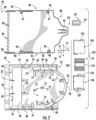
FIG. 2 is a top disassembled view of the components of a fiber optic cassette in accordance with embodiments of the present disclosure; -
FIG. 3 is a side perspective view of a fiber optic splice insert in accordance with embodiments of the present disclosure; -
FIG. 4 is a side view of a fiber optic splice module in accordance with embodiments of the present disclosure; -
FIG. 5 is a side perspective view of an insert module in accordance with embodiments of the present disclosure; -
FIG. 6 is a perspective view illustrating a side tab of a cover of a fiber optic cassette in accordance with embodiments of the present disclosure; and -
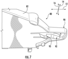
FIG. 7 is a perspective view illustrating a latch of a cover of a fiber optic cassette in accordance with embodiments of the present disclosure. - Reference now will be made in detail to embodiments of the invention, one or more examples of which are illustrated in the drawings. Each example is provided by way of explanation of the invention, not limitation of the invention. In fact, it will be apparent to those skilled in the art that various modifications and variations can be made in the present invention without departing from the scope or spirit of the invention. For instance, features illustrated or described as part of one embodiment can be used with another embodiment to yield a still further embodiment. Thus, it is intended that the present invention covers such modifications and variations as come within the scope of the appended claims and their equivalents.
- Referring now to
FIGS. 1 through 7 , embodiments of fiberoptic cassettes 10 andsplice modules 100 are shown. Fiberoptic cassettes 10 in accordance with the present disclosure advantageously provide improved patch and splice solutions for high density fiber optic environments. For example, fiberoptic cassettes 10 in accordance with the present disclosure advantageously provide improved cable routing into thecassettes 10. Further,splice modules 100 allow for splicing to be completed outside of thecassettes 10 and then moved into thecassettes 10. Further,cassettes 10 are relatively more compact and space-efficient than known patch and splice cassettes. - A mutually orthogonal coordinate system may be defined for
cassette 10 in accordance with the present disclosure. The coordinate system may include alongitudinal axis 12, alateral axis 14, and atransverse axis 16, each of which may be mutually orthogonal to the others in the coordinate system. - A
cassette 10 in accordance with the present disclosure may include acassette body 20 which defines aninterior 21.Body 20 may extend along the longitudinal axis between afront 22 and a rear 23, and may extend along the lateral axis between afirst side 24 and asecond side 25, and may extend along thetransverse axis 16 between abottom 26 and atop 27. Abase wall 30 may be positioned at thebottom 26, and first andsecond side walls first side 24 andsecond side 25, respectively. Arear wall 36 may be positioned at or extend to the rear 23. For example, in exemplary embodiments as shown, therear wall 36 is or includes a curved portion that extends from a position between thefront 22 and rear 23 (in exemplary embodiments moreproximate rear 23 than front 22) to the rear 23. -
Cassette 10 may further include a plurality of fiberoptic adapter apertures 40 which may be defined in thecassette body 20. For example,such adapter apertures 40 may be defined at thefront 22, as shown. Eachadapter aperture 40 may accommodate one or more fiberoptic adapters 42 therein. In exemplary embodiments, no fiber optic adapter apertures or adapters are defined in the rear 23 orrear wall 36. -
Cassette 10 may further include a plurality ofretention tabs 44 disposed in theinterior 21 ofbody 20.Retention tabs 44 may be positioned abovebase wall 30 to allow fibers within theinterior 21 to be routed between theretention tabs 44 andbase wall 30.Retention tabs 44 may be advantageously positioned in theinterior 21 such that fibers can be routed therein without exceeding bending radius limits thereof. -
Cassette 10 may further include one ormore side tabs Side tabs first side 24 andsecond side 25, respectively. For example,side tabs first side wall 32 andsecond side wall 34, respectively, into theinterior 21, such as along thelateral axis 14. As discussed herein,side tabs cassette 10 to removably connect the cover to thecassette body 20. -
Cassette 10 may further include aside channel 50 defined therein.Side channel 50 may, for example, be defined at thefirst side 24, such as between the rear 23 andfront 22 along thelongitudinal axis 12. Theside channel 50 may extend, such as along thelongitudinal axis 12, between anentry aperture 52 and anexit aperture 54. Theentry aperture 52 may provide an entry into theside channel 50 from exterior to thecassette 10, and theexit aperture 54 may provide an exit from theside channel 50 into a remainder of the interior 21.Entry aperture 52 may be spaced from the rear 23, as shown. -
Side channel 50 may generally facilitate the entry of fiber optic cables and/or buffer tubes into thecassette 10 for splicing and connection purposes. A cable/buffer tube may enter theside channel 50 through theentry aperture 52 and exit theside channel 50 into the remainder of the interior 21 through theexit aperture 54. Further, theside channel 50 may be secured to thecassette 10 within theside channel 50. For example, aninsert module 60 may be removable insertable into theside channel 50. The cable/buffer tube may advantageously be insertable into theinsert module 60, and theinsert module 60 and cable/buffer tube then inserted into theside channel 50 to secure the cable/buffer tube to thecassette 10. - In some embodiments, the
side channel 50 may be divided into various portions, such as anentry portion 53,exit portion 55, andintermediate portion 57.Partitions 58 may subdivide theside channel 50 into such portions. In exemplary embodiments, theinsert module 60 may be removably insertable into theintermediate portion 57. -
Insert module 60 may, for example, be formed from a suitably resilient material such as rubber, such as in exemplary embodiments vulcanized rubber. Alternatively, other suitable materials may be utilized.Insert module 60 may include abody 62 which defines achannel 64 in which one or more cables/buffer tubes may be inserted.Channel 64 may include one ormore channel portions 65', 65". In exemplary embodiments, eachchannel portion 65 may have a generally elliptical cross-sectional profile. When theinsert module 60 is inserted in thecassette 10, thechannel portions 65 may be stacked and aligned along thetransverse axis 16. Further, eachchannel portion 65', 65" may have amaximum width 66', 66". In exemplary embodiments, themaximum width 66" may be greater than the maximum width 66'. Further, in exemplary embodiments, channel portion 65' may be abovechannel portion 65" (e.g. relatively closer to top 27) along thetransverse axis 16. Still further, in exemplary embodiments, a portion ofbody 62 may be stacked above thechannel 64 andchannel portions 65 thereof, such that the cables/buffer tubes are secured between thebody 62 andbase wall 30. -
Cassette 10 may further include asplice module receptacle 70 defined in thecassette body 20, such as within the interior 21.Receptacle 70 may provide a location for removably connecting asplice module 100 to thecassette 10.Splice module receptacle 70 may, for example, include aframe 72 and/or one ormore clips 74 which removable secure thesplice module 100 in the interior 21. - As discussed, a
splice module 100 may be provided in acassette 10. Thesplice module 100 may, for example, be removably insertable into thesplice module receptacle 70.Splice module 100 may include asplice insert 102, and may further include aholder base 104 and aholder cover 106. Theinsert 102 may, for example, be positionable between theholder base 104 andholder cover 106, such that when assembled theinsert 102 is sandwiched between theholder base 104 andholder cover 106.Holder base 104 andholder cover 106 may be removably connectable to each other, such as viaclips insert 102 therebetween. - When inserted into a
cassette 10, such as the interior 21 thereof, asplice module 100 may be inserted into and secured withinreceptacle 70. In some embodiments, for example,module 100 may be inserted within theframe 72. In some embodiments, for example,module 100 may be secured within receptacle by contact ofclips 74 with thebase 104 and/orcover 106. -
Splice insert 102 may include aninsert body 110 which includes afirst side 112 and an opposingsecond side 114. A plurality offirst channels 116 may be defined in theinsert body 110, such as on thefirst side 112 thereof. One or moresecond channels 118 may be defined in theinsert body 110, such as on thesecond side 114 thereof. - Each
first channel 116 may have amaximum width 117, and eachsecond channel 118 may have amaximum width 119. In exemplary embodiments, themaximum width 119 of anysecond channel 118 is greater than themaximum width 117 of anyfirst channel 116.First channels 116 may, for example, be designed to accommodate one or more single splice fibers, whilesecond channels 118 may, for example, be designed to accommodate one or more ribbon splices (including for example intermittently bonded ribbon splices). - In exemplary embodiments, the
first channels 116 and second channel(s) 118 may be aligned in a linear array. When thesplice module 100 is inserted in thecassette 10, the linear array may extend along thelateral axis 114. - In exemplary embodiments, a
second channel 118 may be positioned between afirst portion 120 of thefirst channels 116 and asecond portion 122 of thefirst channels 116. Each portion may include one or morefirst channels 116, such as in exemplary embodiments a plurality offirst channels 116. In exemplary embodiments, thefirst portion 120 andsecond portion 122 include the same number offirst channels 116. - Each
first channel 116 may include one ormore channel portions 115', 115". In exemplary embodiments, eachchannel portion 115 may have a generally elliptical cross-sectional profile. When thesplice module 100 is inserted in thecassette 10, thechannel portions 115 may be stacked and aligned along thetransverse axis 16. Further, themaximum width 117 in eachchannel portion 115', 115" may in exemplary embodiments be the same. Alternative, themaximum width 117 in a channel portion 115' may be different from themaximum width 117 of achannel portion 115" in achannel 116. - A
cassette 10 in accordance with the present disclosure may further include acover 80 which is removably connectable to thecassette body 20, such as at the top 27 thereof. When connected, the interior 21 may be disposed between thecover 80 andbase wall 30 along thetransverse axis 16.Cover 80 may include acover body 82 which, when connected tocassette body 20, extends along thelongitudinal axis 12 between a front 82 and a rear 83 and extends along thelateral axis 14 between afirst side 84 and asecond side 85. -
Cover 80 may further include a plurality oftabs 90 which extend from the front 82 along thelongitudinal axis 12. When thecover 80 is removably connected to thebody 20, thetabs 90 may be removably inserted into the interior 21. More particularly, in exemplary embodiments, each of the plurality oftabs 90 may be removably insertable into one of the plurality ofadapter apertures 40. Accordingly, when thecover 80 is removably connected to thebody 20, thetabs 90 may be removably inserted into theapertures 40.Tabs 90 thus align and secure thecover 80 with respect to thebody 20. -
Cover 80 may further include alatch 92, which may be proximate the rear 83.Latch 92 may, for example, include astep 93. Thelatch 92, and in particular thestep 93 thereof, may contact thebody 20, such as therear wall 36 thereof, when thecover 80 is removably connected to thecassette body 20. Further, to disconnect thecover 80, a user may need to manipulate thelatch 92 such that thelatch 92, and in particular thestep 93 thereof, is out of contact with thebody 20, such as therear wall 36 thereof.Latch 92 thus secures thecover 80 to thebody 20. -
Cover 80 may further include one ormore side tabs Side tabs first side 84 andsecond side 85, respectively. For example, whencover 80 is removably connected tocassette body 20,side tabs cover body 82 into the interior 21, such as along thetransverse axis 16. - Each
tab tab cassette body 20, as discussed herein. For example, eachtab slot Tabs slots cover 80 is removably connected to thecassette body 20.Tabs cover 80 with respect to thebody 20. - This written description uses examples to disclose the invention, including the best mode, and also to enable any person skilled in the art to practice the invention, including making and using any devices or systems and performing any incorporated methods. The patentable scope of the invention is defined by the claims, and may include other examples that occur to those skilled in the art. Such other examples are intended to be within the scope of the claims if they include structural elements that do not differ from the literal language of the claims, or if they include equivalent structural elements with insubstantial differences from the literal languages of the claims.
Claims (15)
- A fiber optic cassette (10) defining a mutually orthogonal coordinate system having a longitudinal axis (12), a lateral axis (14), and a transverse axis (16), the fiber optic cassette (10) comprising:a cassette body (20), the cassette body (20) extending along the longitudinal axis (12) between a front (22) and a rear (23), extending along the lateral axis (14) between a first side (24) and a second side (25), and extending along the transverse axis (16) between a bottom (26) and a top (27), the cassette body (20) comprising a side channel (50) formed at the first side (24), the side channel (50) configured to receive an insert module (60) removably insertable into the side channel (50);a plurality of fiber optic adapter apertures (40) defined at the front (22) of the cassette body (20); anda cover (80), the cover (80) removably connectable to the cassette body (20), wherein the cover (80) comprises a cover body (82) extending along the longitudinal axis (12) between a front (82) and a rear (83), and wherein the cover (80) further comprises a plurality of tabs (90) extending from the front (82) along the longitudinal axis (12), each of the plurality of tabs (90) removably insertable into one of the plurality of fiber optic adapter apertures (40) along the longitudinal axis (12) when the cover (80) is removably connected to the cassette body (20).
- The fiber optic cassette (10) of claim 1, comprising a splice module (100) removably insertable into the cassette body (20).
- The fiber optic cassette (10) of claim 2, wherein the splice module (100) comprises a holder base (104), a holder cover (106), and a splice insert (102).
- The fiber optic cassette (10) of claim 3, wherein the splice insert (102) is positionable between the holder base (104) and the holder cover (106).
- The fiber optic cassette (10) of claim 4, wherein the holder cover (106) is removably connectable to the holder base (104).
- The fiber optic cassette (10) of claim 2, wherein the splice module (100) comprises a splice insert (102), the splice insert (102) comprising an insert body (110) comprising a first side (112) and an opposing second side (114), the insert body (110) defining a plurality of first channels (116) on the first side (112) and a second channel (118) on the second side (114).
- The fiber optic cassette (10) of claim 6, the second channel (118) having a maximum width which is greater than a maximum width of any of the plurality of first channels (116).
- The fiber optic cassette (10) of claim 6, wherein the plurality of first channels (116) and the second channel (118) are aligned in a linear array.
- The fiber optic cassette (10) of claim 8, wherein the second channel (118) is positioned between a first portion (120) of the plurality of first channels (116) and a second portion (122) of the plurality of first channels (116) in the linear array.
- The fiber optic cassette (10) of claim 8 or claim 9, wherein the plurality of first channels (116) and the second channel (118) are configured to respectively receive a spliced fiber.
- The fiber optic cassette (10) of claim 6, wherein each of the plurality of first channels (116) comprises a plurality of channel sections (115).
- The fiber optic cassette (10) of any preceding claim, wherein the insert module (60) is removably insertable into an intermediate portion (57) of the side channel (50) defined at the first side (24) of the cassette body (20).
- The fiber optic cassette (10) of any preceding claim, wherein a channel is defined in the insert module (60), the channel comprising a plurality of channel sections.
- The fiber optic cassette (10) of any preceding claim, wherein the cover (80) further comprises a latch (92) proximate the rear (83), the latch (92) comprising a step (93) which contacts the cassette body (20) when the cover (80) is removably connected to the cassette body (80).
- The fiber optic cassette (10) of any preceding claim, wherein the cassette body (20) comprises at least one tab (46, 48) disposed at the first side (24) and at the second side (25), wherein the cover body (82) extends along the lateral axis (14) between a first side (84) and a second side (85), wherein the cover (80) further comprises at least one tab (96, 98) disposed at the first side (84) of the cover (80) and the second side (85) of the cover (80), each of the at least one tab (96, 98) of the cover (80) defining a slot (97, 98), and wherein the tabs (46, 48) of the cassette body (20) are removably insertable into the slots (97, 98) of the cover (80) when the cover (80) is removably connected to the cassette body (20).
Applications Claiming Priority (3)
| Application Number | Priority Date | Filing Date | Title |
|---|---|---|---|
| US16/456,558 US10845561B1 (en) | 2019-06-28 | 2019-06-28 | Fiber optic cassettes and splice modules |
| EP20747209.3A EP3966614B1 (en) | 2019-06-28 | 2020-06-03 | Fiber optic cassettes and splice modules |
| PCT/US2020/035819 WO2020263514A1 (en) | 2019-06-28 | 2020-06-03 | Fiber optic cassettes and splice modules |
Related Parent Applications (1)
| Application Number | Title | Priority Date | Filing Date |
|---|---|---|---|
| EP20747209.3A Division EP3966614B1 (en) | 2019-06-28 | 2020-06-03 | Fiber optic cassettes and splice modules |
Publications (2)
| Publication Number | Publication Date |
|---|---|
| EP4455753A2 true EP4455753A2 (en) | 2024-10-30 |
| EP4455753A3 EP4455753A3 (en) | 2025-01-22 |
Family
ID=71842791
Family Applications (2)
| Application Number | Title | Priority Date | Filing Date |
|---|---|---|---|
| EP24194373.7A Pending EP4455753A3 (en) | 2019-06-28 | 2020-06-03 | Fiber optic cassettes and splice modules |
| EP20747209.3A Active EP3966614B1 (en) | 2019-06-28 | 2020-06-03 | Fiber optic cassettes and splice modules |
Family Applications After (1)
| Application Number | Title | Priority Date | Filing Date |
|---|---|---|---|
| EP20747209.3A Active EP3966614B1 (en) | 2019-06-28 | 2020-06-03 | Fiber optic cassettes and splice modules |
Country Status (8)
| Country | Link |
|---|---|
| US (4) | US10845561B1 (en) |
| EP (2) | EP4455753A3 (en) |
| CA (1) | CA3144832A1 (en) |
| DK (1) | DK3966614T3 (en) |
| ES (1) | ES2994805T3 (en) |
| MX (2) | MX2021015291A (en) |
| PL (1) | PL3966614T3 (en) |
| WO (1) | WO2020263514A1 (en) |
Families Citing this family (7)
| Publication number | Priority date | Publication date | Assignee | Title |
|---|---|---|---|---|
| US10845561B1 (en) * | 2019-06-28 | 2020-11-24 | Afl Telecommunications Llc | Fiber optic cassettes and splice modules |
| USD1080555S1 (en) * | 2019-11-06 | 2025-06-24 | Optical Cable Corporation | Fiber splice cassette |
| WO2022061129A1 (en) | 2020-09-17 | 2022-03-24 | Panduit Corp. | Optical distribution and splice frame including cassettes |
| US11740421B2 (en) | 2021-02-18 | 2023-08-29 | Commscope Technologies Llc | Communications panel system |
| US11971598B2 (en) | 2021-02-18 | 2024-04-30 | Commscope Technologies Llc | Tray arrangements for cassettes |
| USD1009801S1 (en) | 2021-05-07 | 2024-01-02 | DMSI International | Splice cassette |
| US12259590B2 (en) * | 2021-11-29 | 2025-03-25 | Corning Research & Development Corporation | Fiber-optic apparatus |
Family Cites Families (97)
| Publication number | Priority date | Publication date | Assignee | Title |
|---|---|---|---|---|
| US4397088A (en) | 1981-02-09 | 1983-08-09 | The Toro Company | Power equipment unit with split handle |
| US5071211A (en) | 1988-12-20 | 1991-12-10 | Northern Telecom Limited | Connector holders and distribution frame and connector holder assemblies for optical cable |
| US4920667A (en) | 1989-04-03 | 1990-05-01 | Dixon James W | Snow removal device |
| DE4119829A1 (en) | 1991-06-15 | 1992-12-17 | Rose Walter Gmbh & Co Kg | DEVICE FOR DIVIDING LIGHTWAVE GUIDE CABLES OR - Veins |
| US5161318A (en) | 1991-07-12 | 1992-11-10 | Bergman Ronald E | Power sweeping tool |
| FR2687800B1 (en) * | 1992-02-21 | 1994-04-08 | Mars Actel | ADAPTABLE CASSETTE FOR LOVING AND SPLICING OPTICAL FIBERS. |
| FR2687801B1 (en) * | 1992-02-21 | 1997-01-03 | Mars Actel | OPTICAL FIBER CASSETTE. |
| US5323480A (en) * | 1992-11-25 | 1994-06-21 | Raychem Corporation | Fiber optic splice closure |
| IT1271281B (en) * | 1994-12-15 | 1997-05-27 | Pirelli Cavi Spa | CONTAINER FOR HOUSING OPTICAL COMPONENTS IN AN ACTIVE FIBER OPTIC AMPLIFIER |
| DE4415218C1 (en) | 1994-04-26 | 1995-10-19 | Krone Ag | Housing for optical components |
| US5530786A (en) * | 1995-05-30 | 1996-06-25 | The Whitaker Corporation | Holding for optical fiber splice couplings |
| JPH09178995A (en) | 1995-12-21 | 1997-07-11 | Fujikura Ltd | MT connector holder and optical fiber cable with MT connector using the same |
| JPH09304631A (en) | 1996-05-14 | 1997-11-28 | Japan Riicom:Kk | Closure for cable connection |
| US5734777A (en) | 1996-06-18 | 1998-03-31 | Siecor Corporation | Strain relief device for plurality of optical ribbon fibers |
| KR100242412B1 (en) | 1996-10-25 | 2000-03-02 | 윤종용 | Packaging box for fixing optical element of optical fiber amplifier |
| US5802228A (en) | 1996-12-16 | 1998-09-01 | Lucent Technologies Inc. | Optical package with removable fiber termination |
| US5893224A (en) | 1997-09-03 | 1999-04-13 | Murray, Inc. | Cutting arrangement for a snow blower |
| GB9805760D0 (en) | 1998-03-18 | 1998-05-13 | Raychem Sa Nv | Side entry cable guide |
| AU751741B2 (en) | 1998-08-31 | 2002-08-29 | Whitaker Corporation, The | Fibre optic splice holder |
| US6353697B1 (en) | 1999-07-30 | 2002-03-05 | Lucent Technologies, Inc. | Modular layered splice holder |
| US6249636B1 (en) | 1999-09-07 | 2001-06-19 | Lucent Technologies, Inc. | High density fusion splice holder |
| US6259851B1 (en) | 1999-09-17 | 2001-07-10 | Lucent Technologies Inc. | High density fiber splice holder |
| DE10019104C2 (en) | 2000-04-18 | 2003-04-03 | Krone Gmbh | Duplex connector for fiber optic connectors |
| JP4516189B2 (en) | 2000-07-17 | 2010-08-04 | 本田技研工業株式会社 | Snow removal machine with snow plate |
| WO2002027882A1 (en) | 2000-09-26 | 2002-04-04 | Andrews Kent And Stone Pty Ltd | Ducting associated with rail track and installing apparatus |
| US6435580B1 (en) | 2001-03-29 | 2002-08-20 | Willie Lock | Hand-held shovel |
| US6512876B2 (en) | 2001-04-25 | 2003-01-28 | Lucent Technologies Inc. | Fiber splice tray |
| US6567601B2 (en) | 2001-06-19 | 2003-05-20 | Lucent Technologies Inc. | Fiber-optic cable routing and management system and components |
| US6948569B1 (en) | 2004-09-16 | 2005-09-27 | Uniontools, Inc. | Snow auger assembly |
| US20060070265A1 (en) | 2004-09-30 | 2006-04-06 | Joseph Cohen | Snow thrower with an ergonomic handle |
| GB0423743D0 (en) | 2004-10-26 | 2004-11-24 | Tyco Electronics Raychem Nv | A signal distribution assembly and a connector holder for use therewith |
| US7314096B2 (en) | 2004-10-27 | 2008-01-01 | The Toro Company | Adjustable handle for portable tool |
| US7257909B2 (en) | 2004-10-27 | 2007-08-21 | The Toro Company | Convertible yard tool |
| JP2006227146A (en) | 2005-02-16 | 2006-08-31 | Yazaki Corp | Optical cable connection structure |
| US7310471B2 (en) | 2005-08-25 | 2007-12-18 | Adc Telecommunications, Inc. | Stackable splice chip device |
| CN2825735Y (en) | 2005-09-07 | 2006-10-11 | 宁波奇亚园林工具有限公司 | Hand-pushed snow plough |
| DE202006006016U1 (en) | 2006-04-11 | 2006-06-29 | CCS Technology, Inc., Wilmington | Distribution device and handling device for optical fibers |
| WO2007123525A1 (en) | 2006-04-24 | 2007-11-01 | Joseph Cohen | Snow thrower with an ergonomic handle |
| US7603018B2 (en) * | 2007-01-16 | 2009-10-13 | Tyco Electronics Corporation | Cable enclosure assemblies and methods for using the same |
| CN201047073Y (en) | 2007-04-27 | 2008-04-16 | 赵玉石 | Road snow-clearing power spade |
| US7418186B1 (en) * | 2007-05-11 | 2008-08-26 | Preformed Line Products Company | Fiber retention sleeve |
| US7607244B2 (en) | 2007-10-09 | 2009-10-27 | Viv Engineering Inc. | Snow-plowing apparatus |
| US8005333B2 (en) * | 2008-05-20 | 2011-08-23 | Tyco Electronics Corporation | Tap-off closure systems and methods for using the same |
| CN201218859Y (en) | 2008-05-29 | 2009-04-08 | 上海思南电力通信有限公司 | Optical cable fixing holder used for optical cable switching box |
| US8824850B2 (en) * | 2010-01-26 | 2014-09-02 | Adc Telecommunications, Inc. | Insect-infestation prevention device for a telecommunications equipment housing |
| US8385711B2 (en) | 2010-04-30 | 2013-02-26 | Corning Cable Systems Llc | Multi-configurable splice holder |
| US8660397B2 (en) | 2010-04-30 | 2014-02-25 | Corning Cable Systems Llc | Multi-layer module |
| US20120134639A1 (en) * | 2010-11-30 | 2012-05-31 | Giraud William J | Module with adapter side entry opening |
| US8254742B2 (en) | 2010-05-11 | 2012-08-28 | Commscope, Inc. Of North Carolina | Splice holder |
| WO2012074982A1 (en) | 2010-11-30 | 2012-06-07 | Corning Cable Systems Llc | Fiber device holder and strain relief device |
| WO2012074688A2 (en) | 2010-12-01 | 2012-06-07 | 3M Innovative Properties Company | Fiber organizer and distribution box |
| CN202672085U (en) | 2011-02-23 | 2013-01-16 | 姜日华 | Flat shovel snow-removing machine |
| CN201990976U (en) | 2011-03-16 | 2011-09-28 | 张芳廷 | Snow shovel |
| US9207422B2 (en) * | 2011-10-26 | 2015-12-08 | All Systems Broadband, Inc. | Holders for optical fiber splice sleeves and passive optical components |
| AU2013323161B2 (en) * | 2012-09-28 | 2017-06-22 | Afl Telecommunications Llc | Field installable optical module with cable attachment |
| US10718919B2 (en) | 2012-09-28 | 2020-07-21 | Afl Telecommunications Llc | Field-installable optical module with configurable cable attachment and internal cable management features |
| EP2929387B1 (en) | 2012-12-07 | 2018-10-31 | Corning Optical Communications LLC | Fiber optic modules with splice holder and fiber management features |
| CN105229509B (en) | 2012-12-07 | 2019-03-19 | 康宁光电通信有限责任公司 | Fiber optic module with push rod actuated latch and apparatus for releasably attaching fiber optic module to equipment |
| US9606315B2 (en) | 2013-03-15 | 2017-03-28 | All Systems Broadband, Inc. | Optical fiber ribbon storage |
| US10061089B2 (en) * | 2013-09-20 | 2018-08-28 | Adva Optical Networking Se | Fiber optic component holding device for fibers in side-by-side contact |
| EP3149520B1 (en) * | 2014-05-27 | 2021-09-01 | Corning Research & Development Corporation | Fiber management assemblies and trays and network interface devices incorporating such assemblies and trays |
| CA2964011A1 (en) | 2014-10-20 | 2016-04-28 | Belden Canada Inc. | Splice holder |
| US9778433B2 (en) | 2014-10-27 | 2017-10-03 | Commscope Technologies Llc | Splice module for fiber blade |
| CN104314034A (en) | 2014-10-30 | 2015-01-28 | 樊红海 | Snow shovel with helical blades |
| CN204401540U (en) | 2015-01-03 | 2015-06-17 | 吉林省临江市永悦机械制造有限公司 | A kind of carry formula auger snow removing shovel |
| US9494760B2 (en) | 2015-02-17 | 2016-11-15 | 3M Innovative Properties Company | Highly configurable fiber-optic interconnection tray |
| CN104912020A (en) | 2015-05-11 | 2015-09-16 | 浙江亚特电器有限公司 | Hybrid-driven snow sweeper |
| EP3303848B1 (en) | 2015-06-05 | 2022-08-24 | MTD products Inc | Blower with intake closure |
| WO2017034931A1 (en) * | 2015-08-21 | 2017-03-02 | Commscope Technologies Llc | Telecommunications module |
| CN106759044A (en) | 2015-11-21 | 2017-05-31 | 青岛世纪云帆实业有限公司 | The snow blade of snow device is raised with spiral |
| CN206110070U (en) | 2015-11-30 | 2017-04-19 | 南京德朔实业有限公司 | Snow remover |
| CN106826100A (en) | 2015-12-06 | 2017-06-13 | 青岛世纪云帆实业有限公司 | The installation manufacturing process of improved snow throwing shoveling |
| CN205975462U (en) | 2016-06-29 | 2017-02-22 | 浙江亚特电器有限公司 | Hybrid snowplow |
| CN105954850B (en) | 2016-07-14 | 2022-11-04 | 苏州安捷讯光电科技股份有限公司 | Baking clamp |
| US10941533B2 (en) | 2016-09-29 | 2021-03-09 | Nicholas French | Shovel assembly |
| EP3327477B1 (en) | 2016-09-30 | 2020-03-18 | Huawei Technologies Co., Ltd. | Optical fiber fusion module, optical fiber fusion frame |
| CN206467623U (en) | 2016-10-20 | 2017-09-05 | 国家电网公司 | One kind clears the snow instrument |
| CA2984824A1 (en) | 2016-11-08 | 2018-05-08 | Ortronics, Inc. | Splice managers and related methods of use |
| US10466434B2 (en) | 2016-12-12 | 2019-11-05 | Multilink Inc. | Fiber optic splice tray and enclosure and method |
| US20180163356A1 (en) | 2016-12-12 | 2018-06-14 | DMOS Collective, Inc. | Shovel and related methods |
| CN206503109U (en) | 2016-12-29 | 2017-09-19 | 常州格力博有限公司 | Snowplough |
| CN206554006U (en) | 2017-01-18 | 2017-10-13 | 浙江亚特电器有限公司 | A kind of snowplough in motorized adjustment row snow direction |
| CN106801398A (en) | 2017-01-18 | 2017-06-06 | 浙江亚特电器有限公司 | A kind of snowplough in manual regulation row snow direction |
| CN206554005U (en) | 2017-01-18 | 2017-10-13 | 浙江亚特电器有限公司 | A kind of snowplough in manual regulation row snow direction |
| CA3050552A1 (en) | 2017-01-20 | 2018-07-26 | 3975266 Canada Inc | Fiber optic cable extension sleeve for receiving a splice protector of fused fiber strands |
| US11296576B2 (en) | 2017-03-09 | 2022-04-05 | Briggs & Stratton, Llc | Horizontal shaft electric powerhead |
| US10295773B2 (en) | 2017-03-29 | 2019-05-21 | Leviton Manufacturing Co., Inc. | Segregated fiber in a splice cassette |
| CN207277271U (en) | 2017-05-05 | 2018-04-27 | 凌东强 | A kind of highway shovel ice production apparatus |
| CN106939571A (en) | 2017-05-15 | 2017-07-11 | 苏州金莱克精密机械有限公司 | A kind of snowplough of efficient snow throwing |
| WO2018217461A1 (en) | 2017-05-23 | 2018-11-29 | Corning Research & Development Corporation | Mechanical cable entry port |
| CN107294024A (en) | 2017-07-21 | 2017-10-24 | 江苏中天科技股份有限公司 | A kind of OPLC photoelectric integrals floor distribution box |
| US20190064463A1 (en) | 2017-07-25 | 2019-02-28 | Ofs Fitel, Llc | In-line outdoor façade optical fiber distribution closure |
| CN207537948U (en) | 2017-11-29 | 2018-06-26 | 国投物业有限责任公司北京三分公司 | A kind of hand push clear snow multi-function vehicle |
| CN108914866B (en) | 2018-06-07 | 2020-09-29 | 张铁民 | Shovel throwing type snow remover |
| CN108625334B (en) | 2018-06-07 | 2020-11-03 | 张铁民 | Shovel-loading integrated snow sweeper |
| CN208689230U (en) | 2018-10-11 | 2019-04-02 | 湖北楚天电缆实业有限公司 | A kind of optical cable wire clamp |
| US10845561B1 (en) * | 2019-06-28 | 2020-11-24 | Afl Telecommunications Llc | Fiber optic cassettes and splice modules |
-
2019
- 2019-06-28 US US16/456,558 patent/US10845561B1/en active Active
-
2020
- 2020-06-03 MX MX2021015291A patent/MX2021015291A/en unknown
- 2020-06-03 DK DK20747209.3T patent/DK3966614T3/en active
- 2020-06-03 CA CA3144832A patent/CA3144832A1/en active Pending
- 2020-06-03 ES ES20747209T patent/ES2994805T3/en active Active
- 2020-06-03 EP EP24194373.7A patent/EP4455753A3/en active Pending
- 2020-06-03 WO PCT/US2020/035819 patent/WO2020263514A1/en not_active Ceased
- 2020-06-03 PL PL20747209.3T patent/PL3966614T3/en unknown
- 2020-06-03 EP EP20747209.3A patent/EP3966614B1/en active Active
- 2020-10-06 US US17/064,216 patent/US11169346B2/en active Active
-
2021
- 2021-10-19 US US17/505,282 patent/US11789227B2/en active Active
- 2021-12-10 MX MX2025012871A patent/MX2025012871A/en unknown
-
2023
- 2023-09-13 US US18/367,787 patent/US12379560B2/en active Active
Also Published As
| Publication number | Publication date |
|---|---|
| EP3966614B1 (en) | 2024-09-04 |
| PL3966614T3 (en) | 2025-03-31 |
| US20220035113A1 (en) | 2022-02-03 |
| US11169346B2 (en) | 2021-11-09 |
| US20210018711A1 (en) | 2021-01-21 |
| EP3966614A1 (en) | 2022-03-16 |
| US11789227B2 (en) | 2023-10-17 |
| EP4455753A3 (en) | 2025-01-22 |
| CA3144832A1 (en) | 2020-12-30 |
| MX2021015291A (en) | 2022-03-11 |
| US12379560B2 (en) | 2025-08-05 |
| WO2020263514A1 (en) | 2020-12-30 |
| DK3966614T3 (en) | 2024-11-25 |
| US10845561B1 (en) | 2020-11-24 |
| ES2994805T3 (en) | 2025-01-31 |
| US20240004156A1 (en) | 2024-01-04 |
| MX2025012871A (en) | 2025-12-01 |
Similar Documents
| Publication | Publication Date | Title |
|---|---|---|
| US12379560B2 (en) | Fiber optic cassettes and splice modules | |
| US12019299B2 (en) | Fiber optic tray | |
| US6061492A (en) | Apparatus and method for interconnecting fiber cables | |
| US5724467A (en) | Adapter to secure fiber optic connectors within a telecommuniations box | |
| EP2261713B1 (en) | Multi-position fiber optic connector holder | |
| JP4511530B2 (en) | Optical fiber cable distribution frame | |
| US6915057B2 (en) | Cassette for coiling and holding splices between conductors, and an organizer for a plurality of said cassettes | |
| AU2016363767B2 (en) | Cable distribution system with fan out devices | |
| WO2011094154A1 (en) | Insect-infestation prevention device for telecommunications equipment | |
| EP2021853A2 (en) | Multi-directional optical splice organizer | |
| US11899262B2 (en) | Fiber management components for telelcommunications closures | |
| WO2020180619A1 (en) | Track device for a telecommunications product | |
| US12353040B2 (en) | Adapter configured to permit a heat shrink splice holder portion of a fiber splice cassette to hold a mechanical crimp splice protector | |
| US20210364721A1 (en) | Field repairable fiber optic cassette | |
| US20240053563A1 (en) | Optical connectivity module and chassis | |
| US20220057589A1 (en) | Common Module Storage within a Fiber Distribution Hub | |
| US20250147258A1 (en) | Optical fiber management tray assembly with improved access to interior fiber management features | |
| AU2016201870A1 (en) | Multi-position fiber optic connector holder and method |
Legal Events
| Date | Code | Title | Description |
|---|---|---|---|
| PUAI | Public reference made under article 153(3) epc to a published international application that has entered the european phase |
Free format text: ORIGINAL CODE: 0009012 |
|
| STAA | Information on the status of an ep patent application or granted ep patent |
Free format text: STATUS: THE APPLICATION HAS BEEN PUBLISHED |
|
| AC | Divisional application: reference to earlier application |
Ref document number: 3966614 Country of ref document: EP Kind code of ref document: P |
|
| AK | Designated contracting states |
Kind code of ref document: A2 Designated state(s): AL AT BE BG CH CY CZ DE DK EE ES FI FR GB GR HR HU IE IS IT LI LT LU LV MC MK MT NL NO PL PT RO RS SE SI SK SM TR |
|
| PUAL | Search report despatched |
Free format text: ORIGINAL CODE: 0009013 |
|
| AK | Designated contracting states |
Kind code of ref document: A3 Designated state(s): AL AT BE BG CH CY CZ DE DK EE ES FI FR GB GR HR HU IE IS IT LI LT LU LV MC MK MT NL NO PL PT RO RS SE SI SK SM TR |
|
| RIC1 | Information provided on ipc code assigned before grant |
Ipc: G02B 6/44 20060101AFI20241219BHEP |
|
| STAA | Information on the status of an ep patent application or granted ep patent |
Free format text: STATUS: REQUEST FOR EXAMINATION WAS MADE |
|
| 17P | Request for examination filed |
Effective date: 20250721 |
|
| STAA | Information on the status of an ep patent application or granted ep patent |
Free format text: STATUS: EXAMINATION IS IN PROGRESS |
|
| 17Q | First examination report despatched |
Effective date: 20260218 |