EP4455661A1 - Chip detection system for an engine fluid system - Google Patents
Chip detection system for an engine fluid system Download PDFInfo
- Publication number
- EP4455661A1 EP4455661A1 EP24171451.8A EP24171451A EP4455661A1 EP 4455661 A1 EP4455661 A1 EP 4455661A1 EP 24171451 A EP24171451 A EP 24171451A EP 4455661 A1 EP4455661 A1 EP 4455661A1
- Authority
- EP
- European Patent Office
- Prior art keywords
- fluid passage
- emitter
- detector
- ionizing radiation
- electric current
- Prior art date
- Legal status (The legal status is an assumption and is not a legal conclusion. Google has not performed a legal analysis and makes no representation as to the accuracy of the status listed.)
- Pending
Links
Images


Classifications
-
- G—PHYSICS
- G01—MEASURING; TESTING
- G01N—INVESTIGATING OR ANALYSING MATERIALS BY DETERMINING THEIR CHEMICAL OR PHYSICAL PROPERTIES
- G01N33/00—Investigating or analysing materials by specific methods not covered by groups G01N1/00 - G01N31/00
- G01N33/26—Oils; Viscous liquids; Paints; Inks
- G01N33/28—Oils, i.e. hydrocarbon liquids
- G01N33/2888—Lubricating oil characteristics, e.g. deterioration
-
- F—MECHANICAL ENGINEERING; LIGHTING; HEATING; WEAPONS; BLASTING
- F16—ENGINEERING ELEMENTS AND UNITS; GENERAL MEASURES FOR PRODUCING AND MAINTAINING EFFECTIVE FUNCTIONING OF MACHINES OR INSTALLATIONS; THERMAL INSULATION IN GENERAL
- F16N—LUBRICATING
- F16N29/00—Special means in lubricating arrangements or systems providing for the indication or detection of undesired conditions; Use of devices responsive to conditions in lubricating arrangements or systems
-
- G—PHYSICS
- G01—MEASURING; TESTING
- G01N—INVESTIGATING OR ANALYSING MATERIALS BY DETERMINING THEIR CHEMICAL OR PHYSICAL PROPERTIES
- G01N15/00—Investigating characteristics of particles; Investigating permeability, pore-volume or surface-area of porous materials
- G01N15/06—Investigating concentration of particle suspensions
- G01N15/0656—Investigating concentration of particle suspensions using electric, e.g. electrostatic methods or magnetic methods
-
- G—PHYSICS
- G01—MEASURING; TESTING
- G01N—INVESTIGATING OR ANALYSING MATERIALS BY DETERMINING THEIR CHEMICAL OR PHYSICAL PROPERTIES
- G01N23/00—Investigating or analysing materials by the use of wave or particle radiation, e.g. X-rays or neutrons, not covered by groups G01N3/00 – G01N17/00, G01N21/00 or G01N22/00
- G01N23/02—Investigating or analysing materials by the use of wave or particle radiation, e.g. X-rays or neutrons, not covered by groups G01N3/00 – G01N17/00, G01N21/00 or G01N22/00 by transmitting the radiation through the material
- G01N23/06—Investigating or analysing materials by the use of wave or particle radiation, e.g. X-rays or neutrons, not covered by groups G01N3/00 – G01N17/00, G01N21/00 or G01N22/00 by transmitting the radiation through the material and measuring the absorption
- G01N23/12—Investigating or analysing materials by the use of wave or particle radiation, e.g. X-rays or neutrons, not covered by groups G01N3/00 – G01N17/00, G01N21/00 or G01N22/00 by transmitting the radiation through the material and measuring the absorption the material being a flowing fluid or a flowing granular solid
-
- F—MECHANICAL ENGINEERING; LIGHTING; HEATING; WEAPONS; BLASTING
- F16—ENGINEERING ELEMENTS AND UNITS; GENERAL MEASURES FOR PRODUCING AND MAINTAINING EFFECTIVE FUNCTIONING OF MACHINES OR INSTALLATIONS; THERMAL INSULATION IN GENERAL
- F16N—LUBRICATING
- F16N2200/00—Condition of lubricant
- F16N2200/04—Detecting debris, chips, swarfs
-
- F—MECHANICAL ENGINEERING; LIGHTING; HEATING; WEAPONS; BLASTING
- F16—ENGINEERING ELEMENTS AND UNITS; GENERAL MEASURES FOR PRODUCING AND MAINTAINING EFFECTIVE FUNCTIONING OF MACHINES OR INSTALLATIONS; THERMAL INSULATION IN GENERAL
- F16N—LUBRICATING
- F16N2210/00—Applications
- F16N2210/08—Aircraft
-
- G—PHYSICS
- G01—MEASURING; TESTING
- G01N—INVESTIGATING OR ANALYSING MATERIALS BY DETERMINING THEIR CHEMICAL OR PHYSICAL PROPERTIES
- G01N15/00—Investigating characteristics of particles; Investigating permeability, pore-volume or surface-area of porous materials
- G01N2015/0042—Investigating dispersion of solids
- G01N2015/0053—Investigating dispersion of solids in liquids, e.g. trouble
-
- G—PHYSICS
- G01—MEASURING; TESTING
- G01N—INVESTIGATING OR ANALYSING MATERIALS BY DETERMINING THEIR CHEMICAL OR PHYSICAL PROPERTIES
- G01N2223/00—Investigating materials by wave or particle radiation
- G01N2223/20—Sources of radiation
- G01N2223/205—Sources of radiation natural source
-
- G—PHYSICS
- G01—MEASURING; TESTING
- G01N—INVESTIGATING OR ANALYSING MATERIALS BY DETERMINING THEIR CHEMICAL OR PHYSICAL PROPERTIES
- G01N33/00—Investigating or analysing materials by specific methods not covered by groups G01N1/00 - G01N31/00
- G01N33/26—Oils; Viscous liquids; Paints; Inks
- G01N33/28—Oils, i.e. hydrocarbon liquids
- G01N33/2835—Specific substances contained in the oils or fuels
- G01N33/2858—Metal particles
Definitions
- the present disclosure relates generally to the detection of chips or other physical debris in an engine fluid system, and more particularly to the detection of chips the oil system an engine.
- Aircraft engines include oil systems used for cooling and lubrication. Because the oil flowing within such oil systems can collect and carry debris (e.g., "chips") from various mechanical components, the oil needs to be filtered. Oil filters are consumables and are replaced if significant quantities of chips are produced. As such, chip detection systems, or chip detectors, are sometimes used, which used to detect when the quantity of chips within the oil system exceeds an allowable level. Most existing oil system chip detectors are of a magnetic type, wherein a permanent magnet is used to collect ferrous chips within the oil system. The ferrous chips adhere to the detector and bridge an electric circuit, which can be observed by an indicator or detected by the engine control system to determine when the quantity of chips collected exceeds allowable levels.
- chips debris
- chip detectors are sometimes used, which used to detect when the quantity of chips within the oil system exceeds an allowable level.
- Most existing oil system chip detectors are of a magnetic type, wherein a permanent magnet is used to collect ferrous chips within the oil system. The ferrous chips adhere to the detector
- magnetic chip detectors tend to get clogged over time, and have to be regularly cleaned as part of a maintenance action. Therefore, while existing magnetic chip detectors are useful for their intended purpose, improvement is sought.
- a chip detection system for an engine fluid system, the chip detection system comprising: an emitter located in a first position proximate to a fluid passage of the engine fluid system, the emitter including a radioactive source that generates ionizing radiation particles and transmits the ionizing radiation particles through a liquid within the fluid passage; and a detector including a detecting element, the detecting element located in a second position relative to the fluid passage with the liquid disposed between the emitter and the detector, the detecting element generating an electric current in response to the ionizing radiation particles contacting the detector, and a controller in communication with the detector to receive the electric current generated by the detecting element, the controller operable to detect chips in the liquid when the electric current generated by the detecting element is greater than a threshold value of the electric current.
- the chip detection system as defined above and described herein may further include one or more of the following features, in whole or in part, and in any combination.
- the emitter is located externally of the fluid passage on a first side thereof, and the detecting element is located on a second side of the fluid passage, substantially opposite the emitter.
- the emitter is oriented to transmit the ionizing radiation particles transversely through the fluid passage from the first side to the second side.
- the detecting element is dispensed radially outward of a wall of the fluid passage.
- the detecting element is a liner disposed along at least a portion of the fluid passage.
- the liner substantially fully surrounds the fluid passage, at least outside of a region thereof where the emitter is located.
- the liner extends about more than 270 degrees of a perimeter of the fluid passage, extending from a central portion of the liner directly opposite the emitter to remove outer ends of the liner located immediately adjacent the emitter.
- the detecting element is a liner that corresponds in shape to the fluid passage.
- the liner is arcuate and has an at least partially circular cross-sectional shape.
- the liner is located radially outward of the fluid passage.
- the detective element includes a resistive back plate, wherein the further away from the emitter the ionizing radiation particles contact the detective element, the smaller the current produced by the detective element.
- the emitter is located centrally within the fluid passage, the ionizing radiation particles being transmitted radially outwardly from the emitter.
- a method of detecting chips in a liquid flowing through a fluid passage of an engine fluid system comprising: transmitting ionizing radiation particles through the liquid along an initial path from an emitter to a detector; measuring an electric current generated when the ionizing radiation particles contact the detector after passing through the liquid; comparing the current generated to a threshold value of the electric current, the threshold value of the electric current corresponding to a current generated by the detector when the ionizing radiation particles contact the detector after passing uninterrupted through the liquid along the initial path; and detecting chips in the liquid when the electric current generated is greater than the threshold value of the electric current.
- the method as defined above and described herein may further include one or more of the following features, in whole or in part, and in any combination.
- the method includes using a resistive detection element to generate the electric current when the ionizing radiation particles contact the detector.
- the method includes generating the electric current using a liner that surrounds more than 50% of a perimeter of the fluid passage.
- the liner surrounds more than 270 degrees of the perimeter of the fluid passage.
- the method includes generating the electric current using a liner having a shape corresponding to that of the fluid passage.
- the method includes positioning the emitter and the detector diametrically opposite one another on opposite external sides of the fluid passage.
- the method includes transmitting the ionizing radiation particles transversely through the fluid passage.
- the method includes transmitting the ionizing radiation particles radially outwardly from the emitter, the emitter being located centrally within the fluid passage.
- FIG. 1 illustrates an aircraft engine 10 (or simply "engine” 10, which in this exemplary embodiment is a turboprop gas turbine engine) of a type preferably provided for use in subsonic flight, generally comprising in serial flow communication a propeller 12 through which ambient air is propelled, a compressor section 14 for pressurizing the air, a combustor 16 in which the compressed air is mixed with fuel and ignited for generating an annular stream of hot combustion gases, and a turbine section 18 for extracting energy from the combustion gases.
- the engine 10 further includes an engine controller 20 for controlling flight parameters of the engine 10.
- the flight parameters may be, for instance, fuel flow regulation, thrust management, and actuation of valves and pumps required for proper operation of the engine 10.
- the engine 10 as depicted in Fig. 1 is an aircraft engine, and more particularly a gas turbine engine, it is to be understood that the chip detection system as will be described herein can also be used within and/or in conjunction with other types of engines having an engine fluid system, for example automotive engines, marine engines, industrial or static gas turbine engines, power generation systems, other types of aerospace engines, and the like.
- the engine 10 further includes a fluid system 22, operatively connected to one or more rotating components 24 of the engine 10.
- the fluid system 22 is a blurbification system of the engine 10, and may therefore form part of an oil system of the engine.
- the fluid system 22 may therefore be refereed to herein as a lubricating system 22.
- the rotating components 24 may include, for instance, a gearbox 24 of the engine 10 and/or bearing cavities of the engine 10.
- the fluid system 22 includes a fluid circuitry 26, which in the context of a lubrication system will circulate a lubricant, such as oil, into and out of the gearbox 24, the bearing cavities of the engine and/or other components of the engine 10 requiring cooling and/or lubrication.
- a pump 28 is used for circulating the lubricant within the fluid circuitry 26.
- the engine 10 also includes a debris monitoring system 30, which will also be referred to herein as a chip detection system 30, that is operatively connected to the lubrication system 22 and is operable to detect the presence of debris (i.e., "chips") in the liquid medium (e.g., oil) of the lubrication system 22, as will be described in further detail below.
- the debris monitoring system 30 may be connected for example to the fluid circuitry 26 of the lubrication system 22.
- the lubricant debris monitoring system 30 may be configured for collecting debris within the lubricant and for collecting data about the quantity of debris within the lubricant.
- the chip detection system 30 uses ionizing radiation to detect chips and other debris within a liquid medium (or simply "liquid") 34 flowing within a fluid passage 36 of the fluid circuitry 26 in the fluid system 22 (e.g., a lubrication system) of the engine 10.
- the liquid in question is oil and the lubrication system 22 is an oil system of the engine 10.
- ionizing radiation or “ionizing radiation particles” as used herein is understood to mean radiation consisting of particles having sufficient energy to cause ionization in the medium through which it passes. These ionizing radiation particles can include alpha particles, beta particles, gamma rays, X-rays and positrons, which will cause ionization in the fluid medium through which it passes.
- the chip detection system 30 includes generally an emitter 32, having a radioactive source and which produces ionizing radiation particles 38, and a detector 40 adapted to receive the ionizing radiation particles 38 after they have passed through the liquid 34 within the fluid passage 36.
- the detector 40 is operable to determine whether the ionizing radiation particles 38 have passed directly through the liquid 34 without being deflected by any chips within the liquid 34 (as schematically depicted by the transversely-extending path 37 in FIG. 2 ), or whether the ionizing radiation particles 38 have been deflected by chips within the liquid 34 (as schematically depicted using broken lines in FIG. 2 representing the deflected radiation paths 39).
- the emitter 32 of the chip detection system 30 emits low-radiation ionizing radiation particles 38 (for example, but not limited to, beta ( ⁇ ) particles) and transmits these ionizing radiation particles 38 through the liquid 34 within the fluid passage 36 in a first, emitted direction.
- the emitter 32 is located on a first side of the fluid passage 36 and is oriented such as to transmit the ionizing radiation particles 38 transversely through the fluid passage 36 from one side thereof to the other (left to right, in FIG. 2 ).
- the emitter 32 may be placed elsewhere on or near the fluid passage 36, wherever it may be suitable in order to direct the flow of ionizing radiation particles 38 through the liquid (e.g., oil) that is to be monitored for the presence of chips.
- the emitter 32 is thus configured such as to direct a beam or flow of ionizing radiation particles 38 through the liquid 34 along a main emitted path 37.
- the radiation particles 38 will thus tend to follow this path 37, between the emitter 32 and the detector 40, unless they are deflected or scattered by chips within the liquid 34.
- the emitter 32 can be either passive (e.g., a passive radiation source that emits the ionizing radiation particles) or an active system which is controlled to emit ionizing radiation particles 38 as required.
- the chip detection system 30 may in certain embodiments therefore be a passive system, which provides its own excitation.
- the detector 40 is positioned substantially opposite (e.g., diametrically opposite) to the emitter 32 on an opposite side of the fluid passage 36, generally in line with the main emitted path 37 of the ionizing radiation particles 38 that are emitted by the emitter 32, such as to receive (or capture) the ionizing radiation particles 38 after they have passed through the liquid 34 within the fluid passage 36.
- the detector 40 is located substantially opposite the emitter 32, for example on a second side of the fluid passage 36 with the emitter 32 located on a first side of the fluid passage 36.
- the detector 40 includes a detecting element 45 in the form of a liner which is located outside (e.g., radially outward of) the fluid passage 36 (as shown in FIG. 2 ).
- the detecting element 45 may be located on an inner surface of the wall of fluid passage 36, and thus may be directly exposed to the liquid 34.
- the detecting element 45 may simply be referred to herein as the "liner" 45, however it is to be understood that the detecting element 45 may also take other forms.
- the liner 45 of the detector 40 has a shape which corresponds to that of the fluid passage 36.
- the fluid passage 36 is tubular and has an at least partially circular cross-sectional shape, and therefore the liner 45 of detector 40 is arcuate and has a radius of curvature similar to that of the outer wall of the fluid passage 36.
- the liner 45 of the detector 40 extends at least partially around the fluid passage 36, extending away from a central portion 41 of the liner 45, defined at the location where the main path 37 of the ionizing radiation particles 38 impacts the detector 40 (at 3 o'clock in FIG. 2 ), towards remote outer ends 43 of the liner 45 which are circumferentially spaced apart from the central portion 41.
- the remote outer ends 43 of the liner 45 of the detector 40 are located proximate to, and on either side of, the emitter 32.
- the liner 45 of the detector 40 extends about more than 50% of the perimeter of the fluid passage. More particularly, the liner 45 extends more than 3 ⁇ 4, or 270 degrees, of the perimeter of the fluid passage 36, extending from the central portion 41 opposite the emitter 32 to the remove outer ends 43 located immediately adjacent the emitter 32. Accordingly, the liner 45 of the detector 40 in this embodiment substantially fully surrounds the fluid passage 36, outside of the region where the emitter 32 is located.
- the detector 40 will permit the detector 40 to detect not only the presence of chips within the liquid, which would be possible if the liner 45 of the detector 40 was only provided with the central portion 41 located at the point where the main path 37 of the ionizing radiation particles 38 impacts the detector 40, but also permits a quantity or level of chips present in the liquid to be detected as explained below.
- the liner 45 of the detector 40 is operable to release elections when it is exposed to the ionizing radiation particles 38 emitted by the emitter 32. These released electrons create a small electric potential difference (voltage).
- the detective element (or liner) 45 of the detector 40 is a resistive detection element, having for example a resistive back plate 42, wherein the further along the resistive back plate 42 electrons travel, the greater the resistance and thus the smaller the current when compared with that portion or those portions of the liner 45 that are closer to the emitter 32.
- the controller 50 forms part of the chip detection system 30 and is in communication with the detector 40 thereof.
- the controller 50 may instead be integrated into a main engine controller, such as a full authority digital engine controller (FADEC) for example. In all cases, however, the controller 50 remains in communication with the detector 40 as described herein, as well as the emitter 32 when necessary, for the purposes of controlling operation of the chip detection system 30.
- FADEC full authority digital engine controller
- the ionizing radiation particles 38 interact with one or more chips (or other debris) within the liquid 34, the ionizing radiation particles 38 emitted into the liquid by the emitter 32 will scatter, and be redirected along deflected paths 39 for example. This scattering results in ionizing radiation particles 38 interacting with the detector 40 closer to the emitter 32 and, consequently, an increased current will be produced by the detector 40 (because of the reduced electric resistance in the resistive back plate 42 closer to the emitter 32). This increased current is measured by the controller 50 which is in electric communication with the liner 45 of the detector 40.
- the current produced by the detector 40 may be conditioned and amplified by an electric circuit, either within the controller 50 or separate therefrom, as required, and is used by the chip detection system 30 to determine the presence of chips within the liquid. The greater the current produced by the detector 40 and measured by the controller 50 of the chip detection system 30, the greater the number and/or size of chips within the liquid.
- FIG. 3 a schematic view of a chip detection system 130 in accordance with another embodiment is illustrated.
- the chip detection system 130 is similar to the chip detection system 30 of FIG. 2 as described above, with like reference numerals referring to like components, but with certain differences as will be explained.
- the emitter 132 of the chip detection system 130 is located internally within the fluid passage 36, rather than being located on an external side of the passage. As such, in the embodiment of FIG. 3 the emitter 132 is located centrally within the fluid passage 36 such that the liquid 34 within the fluid passage 36 flows around the emitter 132.
- the emitter 132 is capable of emitting ionizing radiation particles 38 is several different radial directions, for example along multiple radially-extending paths 137.
- the ionizing radiation particles 38 are therefore emitted radially outwardly, along these radially-extending paths 137. If the ionizing radiation particles 38 emitted by the emitter 132 come into contact with a chip within the liquid 34, they will be deflected or scattered and thus will change trajectory - leading to deflected radiation paths 139.
- the detector 140 of the chip detection system 130 includes a liner 145 that at least partially surrounds the fluid passage 36 and may, in certain embodiments, extend circumferentially about a full perimeter of the fluid passage 36 and thus may be annular in shape.
- the liner 145 of the detector 140 need not be a resistive element, as per the detector 40 described above. Rather, the liner 145 of the detector 140 can rely on absorption of the ionizing radiation particles 38 to detect the presence of chips within the liquid 34 of the fluid passage 36. Scattered radiation (along scattered radiation paths 139) from the emitter 132 will result in longer transmission paths before the ionizing radiation particles 38 reach the surrounding liner 145 of the detector 140.
- the path between the emitter 132 and liner 145 of the detector 140 is increased, thereby reducing the quantity of ionizing radiation particles 38 that reach the liner 145 and consequently increasing the current measured by the detector 140.
- the chip detection system 30, with the offset emitter 32 rather than the central emitter 132 may also employ such an absorption style system wherein a resistive detecting element is not necessary. Instead, the detector 40 of the chip detection system 30 may similarly use.
- a fluid passage 236 includes a radially outer wall 237 and a radially inner wall 239 that define therebetween a generally annular internal conduit 241 through which the liquid 34 flows. Consequently, a large central cavity 250 is defined radially inward of the radially inner wall 239.
- either of the chip detection system 30 or the chip detection system 130 can be disposed, thereby making the fluid passage 236 a dual-flow passage, within an inner fluid passage (e.g., fluid passage 36) and a radially outer, and annular, fluid passage 236.
- the emitter used in the chip detection system 230 may therefore be a central, absorption type emitter 132 as used in the chip detection system 130, or an emitter 32 as used in the chip detection system 30 but simply placed internally within the cavity 250.
- the detector 140 used in the chip detection system 230 will be the same as that of the chip detection system 130. Alternately, any of the above detectors can be placed directly inside the fluid flow path itself, which also allows the liquid 34 to be used as shielding for the emitted radiation.
- the method 500 includes a step 502 of transmitting the ionizing radiation particles 38 through the liquid 34 along an initial path 37, 137 from an emitter 32, 132, to a detector 40, 140.
- a step 504 an electric current is measured, the electric current being generated when the ionizing radiation particles 38 contact the detector 40, 140 after passing through the liquid 34.
- the electric current generated is then compared to a threshold value of the electric current, the threshold value of the electric current corresponding to a current generated by the detector 40, 140 when the ionizing radiation particles 38 contact the detector after passing uninterrupted through the liquid 34 along the initial path 37, 137.
- the presence of the chips in the liquid 34 is detected when the electric current generated is greater than the threshold value of the electric current.
- the chip detection systems 30, 130, 230 as described herein may also be said to provide a chip detector that comprises an ionizing radiation source (emitter 32, 132) and a detector 40, 140.
- the emitter emits ionizing radiation that is either absorbed, scattered or passes through the liquid medium (e.g., oil).
- the presence of chips in the oil affects the amount of radiation that reaches the detector and where upon the detector it reaches. This is used to indicate the presence of chips in the oil.
- the fluid passage 36 of the fluid system 22 is generally described above in the context of an oil tube or oil passage of an oil system of the engine 10, it is to be understood that the fluid passage 36 may include other liquid-carrying passage within the engine 10, including for example a channel, tube, coupling, orifice or other conduit within which the liquid, which is to be monitored for chips, flows during operation of the engine 10.
- the fluid passage 36 may include other liquid-carrying passage within the engine 10, including for example a channel, tube, coupling, orifice or other conduit within which the liquid, which is to be monitored for chips, flows during operation of the engine 10.
- Yet further modifications could be implemented by a person of ordinary skill in the art in view of the present disclosure, which modifications would be within the scope of the present technology.
Landscapes
- Chemical & Material Sciences (AREA)
- Life Sciences & Earth Sciences (AREA)
- Health & Medical Sciences (AREA)
- Engineering & Computer Science (AREA)
- Pathology (AREA)
- Biochemistry (AREA)
- General Health & Medical Sciences (AREA)
- General Physics & Mathematics (AREA)
- Immunology (AREA)
- Physics & Mathematics (AREA)
- Analytical Chemistry (AREA)
- General Engineering & Computer Science (AREA)
- Food Science & Technology (AREA)
- Chemical Kinetics & Catalysis (AREA)
- General Chemical & Material Sciences (AREA)
- Oil, Petroleum & Natural Gas (AREA)
- Dispersion Chemistry (AREA)
- Medicinal Chemistry (AREA)
- Mechanical Engineering (AREA)
- Investigating Or Analyzing Materials By The Use Of Electric Means (AREA)
- Indicating Or Recording The Presence, Absence, Or Direction Of Movement (AREA)
Abstract
A chip detection system (30; 130; 230) for an engine fluid system (22) includes an emitter (32; 132) located in a first position proximate to a fluid passage (36; 236) of the engine fluid system (22), the emitter (32; 132) including a radioactive source that generates ionizing radiation particles (38) and transmits the ionizing radiation particles (38) through a liquid (34) within the fluid passage (36; 236). A detector (40; 140) includes a detecting element (45; 145) located in a second position relative to the fluid passage (36; 236) with the liquid (34) disposed between the emitter (32; 132) and the detector (40; 140). The detecting element (45; 145) generates an electric current in response to the ionizing radiation particles (38) contacting the detector (40; 140). A controller (50) is in communication with the detector (40; 140) to receive the electric current generated by the detecting element (45; 145). The controller (50) is operable to detect chips in the liquid (34) when the electric current generated by the detecting element (45; 145) is greater than a threshold value of the electric current.
Description
- The present disclosure relates generally to the detection of chips or other physical debris in an engine fluid system, and more particularly to the detection of chips the oil system an engine.
- Aircraft engines include oil systems used for cooling and lubrication. Because the oil flowing within such oil systems can collect and carry debris (e.g., "chips") from various mechanical components, the oil needs to be filtered. Oil filters are consumables and are replaced if significant quantities of chips are produced. As such, chip detection systems, or chip detectors, are sometimes used, which used to detect when the quantity of chips within the oil system exceeds an allowable level. Most existing oil system chip detectors are of a magnetic type, wherein a permanent magnet is used to collect ferrous chips within the oil system. The ferrous chips adhere to the detector and bridge an electric circuit, which can be observed by an indicator or detected by the engine control system to determine when the quantity of chips collected exceeds allowable levels.
- These magnetic chip detectors tend to get clogged over time, and have to be regularly cleaned as part of a maintenance action. Therefore, while existing magnetic chip detectors are useful for their intended purpose, improvement is sought.
- According to an aspect of the present invention, there is provided a chip detection system for an engine fluid system, the chip detection system comprising: an emitter located in a first position proximate to a fluid passage of the engine fluid system, the emitter including a radioactive source that generates ionizing radiation particles and transmits the ionizing radiation particles through a liquid within the fluid passage; and a detector including a detecting element, the detecting element located in a second position relative to the fluid passage with the liquid disposed between the emitter and the detector, the detecting element generating an electric current in response to the ionizing radiation particles contacting the detector, and a controller in communication with the detector to receive the electric current generated by the detecting element, the controller operable to detect chips in the liquid when the electric current generated by the detecting element is greater than a threshold value of the electric current.
- The chip detection system as defined above and described herein may further include one or more of the following features, in whole or in part, and in any combination.
- In an embodiment of the above, the emitter is located externally of the fluid passage on a first side thereof, and the detecting element is located on a second side of the fluid passage, substantially opposite the emitter.
- In another embodiment according to any of the previous embodiments, the emitter is oriented to transmit the ionizing radiation particles transversely through the fluid passage from the first side to the second side.
- In another embodiment according to any of the previous embodiments, the detecting element is dispensed radially outward of a wall of the fluid passage.
- In another embodiment according to any of the previous embodiments, the detecting element is a liner disposed along at least a portion of the fluid passage.
- In another embodiment according to any of the previous embodiments, the liner substantially fully surrounds the fluid passage, at least outside of a region thereof where the emitter is located.
- In another embodiment according to any of the previous embodiments, the liner extends about more than 270 degrees of a perimeter of the fluid passage, extending from a central portion of the liner directly opposite the emitter to remove outer ends of the liner located immediately adjacent the emitter.
- In another embodiment according to any of the previous embodiments, the detecting element is a liner that corresponds in shape to the fluid passage.
- In another embodiment according to any of the previous embodiments, the liner is arcuate and has an at least partially circular cross-sectional shape.
- In another embodiment according to any of the previous embodiments, the liner is located radially outward of the fluid passage.
- In another embodiment according to any of the previous embodiments, the detective element includes a resistive back plate, wherein the further away from the emitter the ionizing radiation particles contact the detective element, the smaller the current produced by the detective element.
- In another embodiment according to any of the previous embodiments, the emitter is located centrally within the fluid passage, the ionizing radiation particles being transmitted radially outwardly from the emitter.
- According to another aspect of the present invention, there is provided a method of detecting chips in a liquid flowing through a fluid passage of an engine fluid system, the method comprising: transmitting ionizing radiation particles through the liquid along an initial path from an emitter to a detector; measuring an electric current generated when the ionizing radiation particles contact the detector after passing through the liquid; comparing the current generated to a threshold value of the electric current, the threshold value of the electric current corresponding to a current generated by the detector when the ionizing radiation particles contact the detector after passing uninterrupted through the liquid along the initial path; and detecting chips in the liquid when the electric current generated is greater than the threshold value of the electric current.
- The method as defined above and described herein may further include one or more of the following features, in whole or in part, and in any combination.
- In an embodiment of the above, the method includes using a resistive detection element to generate the electric current when the ionizing radiation particles contact the detector.
- In another embodiment according to any of the previous embodiments, the method includes generating the electric current using a liner that surrounds more than 50% of a perimeter of the fluid passage.
- In another embodiment according to any of the previous embodiments, the liner surrounds more than 270 degrees of the perimeter of the fluid passage.
- In another embodiment according to any of the previous embodiments, the method includes generating the electric current using a liner having a shape corresponding to that of the fluid passage.
- In another embodiment according to any of the previous embodiments, the method includes positioning the emitter and the detector diametrically opposite one another on opposite external sides of the fluid passage.
- In another embodiment according to any of the previous embodiments, the method includes transmitting the ionizing radiation particles transversely through the fluid passage.
- In another embodiment according to any of the previous embodiments, the method includes transmitting the ionizing radiation particles radially outwardly from the emitter, the emitter being located centrally within the fluid passage.
- Reference is now made to the accompanying figures in which:
-
FIG. 1 is a schematic cross sectional view of an aircraft engine; -
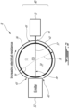
FIG. 2 is a schematic cross-sectional view of an ionizing chip detection system as described herein, for detecting chips within a fluid passage of the aircraft engine ofFig. 1 ; -
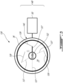
FIG. 3 is a schematic cross-sectional view of an ionizing chip detection system as described herein, for detecting chips within a fluid passage of the aircraft engine ofFig. 1 ; -
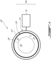
FIG. 4 is a schematic cross-sectional view of an ionizing chip detection system as described herein, for detecting chips within a fluid passage of the aircraft engine ofFig. 1 ; and -
FIG. 5 is a flow chart of a method for detecting chips in a liquid of engine fluid system, as described herein. -
FIG. 1 illustrates an aircraft engine 10 (or simply "engine" 10, which in this exemplary embodiment is a turboprop gas turbine engine) of a type preferably provided for use in subsonic flight, generally comprising in serial flow communication apropeller 12 through which ambient air is propelled, acompressor section 14 for pressurizing the air, acombustor 16 in which the compressed air is mixed with fuel and ignited for generating an annular stream of hot combustion gases, and aturbine section 18 for extracting energy from the combustion gases. Theengine 10 further includes anengine controller 20 for controlling flight parameters of theengine 10. The flight parameters may be, for instance, fuel flow regulation, thrust management, and actuation of valves and pumps required for proper operation of theengine 10. - Although the
engine 10 as depicted inFig. 1 is an aircraft engine, and more particularly a gas turbine engine, it is to be understood that the chip detection system as will be described herein can also be used within and/or in conjunction with other types of engines having an engine fluid system, for example automotive engines, marine engines, industrial or static gas turbine engines, power generation systems, other types of aerospace engines, and the like. - The
engine 10 further includes afluid system 22, operatively connected to one or morerotating components 24 of theengine 10. In accordance with one particular embodiment, thefluid system 22 is a blurbification system of theengine 10, and may therefore form part of an oil system of the engine. Thefluid system 22 may therefore be refereed to herein as a lubricatingsystem 22. Therotating components 24 may include, for instance, agearbox 24 of theengine 10 and/or bearing cavities of theengine 10. Thefluid system 22 includes afluid circuitry 26, which in the context of a lubrication system will circulate a lubricant, such as oil, into and out of thegearbox 24, the bearing cavities of the engine and/or other components of theengine 10 requiring cooling and/or lubrication. In the embodiment shown, apump 28 is used for circulating the lubricant within thefluid circuitry 26. - The
engine 10 also includes adebris monitoring system 30, which will also be referred to herein as achip detection system 30, that is operatively connected to thelubrication system 22 and is operable to detect the presence of debris (i.e., "chips") in the liquid medium (e.g., oil) of thelubrication system 22, as will be described in further detail below. Thedebris monitoring system 30 may be connected for example to thefluid circuitry 26 of thelubrication system 22. The lubricantdebris monitoring system 30 may be configured for collecting debris within the lubricant and for collecting data about the quantity of debris within the lubricant. - Referring now to
FIGS. 2-4 , thechip detection system 30 of theengine 10 will now be described in further detail. - Referring now to
FIG. 2 , a schematic view of thechip detection system 30 in accordance with one embodiment is illustrated. As will be described, thechip detection system 30 uses ionizing radiation to detect chips and other debris within a liquid medium (or simply "liquid") 34 flowing within afluid passage 36 of thefluid circuitry 26 in the fluid system 22 (e.g., a lubrication system) of theengine 10. In a particular embodiment, the liquid in question is oil and thelubrication system 22 is an oil system of theengine 10. The term "ionizing radiation" or "ionizing radiation particles" as used herein is understood to mean radiation consisting of particles having sufficient energy to cause ionization in the medium through which it passes. These ionizing radiation particles can include alpha particles, beta particles, gamma rays, X-rays and positrons, which will cause ionization in the fluid medium through which it passes. - The
chip detection system 30 includes generally anemitter 32, having a radioactive source and which produces ionizingradiation particles 38, and adetector 40 adapted to receive the ionizingradiation particles 38 after they have passed through theliquid 34 within thefluid passage 36. In the manner described in further detail below, thedetector 40 is operable to determine whether theionizing radiation particles 38 have passed directly through theliquid 34 without being deflected by any chips within the liquid 34 (as schematically depicted by the transversely-extendingpath 37 inFIG. 2 ), or whether theionizing radiation particles 38 have been deflected by chips within the liquid 34 (as schematically depicted using broken lines inFIG. 2 representing the deflected radiation paths 39). - More specifically, the
emitter 32 of thechip detection system 30 emits low-radiation ionizing radiation particles 38 (for example, but not limited to, beta (β) particles) and transmits these ionizingradiation particles 38 through theliquid 34 within thefluid passage 36 in a first, emitted direction. In the depicted embodiment, theemitter 32 is located on a first side of thefluid passage 36 and is oriented such as to transmit the ionizingradiation particles 38 transversely through thefluid passage 36 from one side thereof to the other (left to right, inFIG. 2 ). However, it is to be understood that theemitter 32 may be placed elsewhere on or near thefluid passage 36, wherever it may be suitable in order to direct the flow of ionizingradiation particles 38 through the liquid (e.g., oil) that is to be monitored for the presence of chips. Theemitter 32 is thus configured such as to direct a beam or flow of ionizingradiation particles 38 through the liquid 34 along a main emittedpath 37. Theradiation particles 38 will thus tend to follow thispath 37, between theemitter 32 and thedetector 40, unless they are deflected or scattered by chips within the liquid 34. Theemitter 32 can be either passive (e.g., a passive radiation source that emits the ionizing radiation particles) or an active system which is controlled to emitionizing radiation particles 38 as required. Thechip detection system 30 may in certain embodiments therefore be a passive system, which provides its own excitation. - The
detector 40 is positioned substantially opposite (e.g., diametrically opposite) to theemitter 32 on an opposite side of thefluid passage 36, generally in line with the main emittedpath 37 of theionizing radiation particles 38 that are emitted by theemitter 32, such as to receive (or capture) theionizing radiation particles 38 after they have passed through the liquid 34 within thefluid passage 36. In the depicted embodiment, thedetector 40 is located substantially opposite theemitter 32, for example on a second side of thefluid passage 36 with theemitter 32 located on a first side of thefluid passage 36. - The
detector 40 includes a detectingelement 45 in the form of a liner which is located outside (e.g., radially outward of) the fluid passage 36 (as shown inFIG. 2 ). Alternately, the detectingelement 45 may be located on an inner surface of the wall offluid passage 36, and thus may be directly exposed to the liquid 34. The detectingelement 45 may simply be referred to herein as the "liner" 45, however it is to be understood that the detectingelement 45 may also take other forms. - In certain embodiments, the
liner 45 of thedetector 40 has a shape which corresponds to that of thefluid passage 36. For example, in the embodiment ofFIG. 2 , thefluid passage 36 is tubular and has an at least partially circular cross-sectional shape, and therefore theliner 45 ofdetector 40 is arcuate and has a radius of curvature similar to that of the outer wall of thefluid passage 36. Theliner 45 of thedetector 40 extends at least partially around thefluid passage 36, extending away from acentral portion 41 of theliner 45, defined at the location where themain path 37 of theionizing radiation particles 38 impacts the detector 40 (at 3 o'clock inFIG. 2 ), towards remote outer ends 43 of theliner 45 which are circumferentially spaced apart from thecentral portion 41. In the embodiment ofFIG. 2 , the remote outer ends 43 of theliner 45 of thedetector 40 are located proximate to, and on either side of, theemitter 32. In the embodiment ofFIG. 2 , theliner 45 of thedetector 40 extends about more than 50% of the perimeter of the fluid passage. More particularly, theliner 45 extends more than ¾, or 270 degrees, of the perimeter of thefluid passage 36, extending from thecentral portion 41 opposite theemitter 32 to the remove outer ends 43 located immediately adjacent theemitter 32. Accordingly, theliner 45 of thedetector 40 in this embodiment substantially fully surrounds thefluid passage 36, outside of the region where theemitter 32 is located. This will permit thedetector 40 to detect not only the presence of chips within the liquid, which would be possible if theliner 45 of thedetector 40 was only provided with thecentral portion 41 located at the point where themain path 37 of theionizing radiation particles 38 impacts thedetector 40, but also permits a quantity or level of chips present in the liquid to be detected as explained below. - The
liner 45 of thedetector 40 is operable to release elections when it is exposed to theionizing radiation particles 38 emitted by theemitter 32. These released electrons create a small electric potential difference (voltage). The detective element (or liner) 45 of thedetector 40 is a resistive detection element, having for example aresistive back plate 42, wherein the further along theresistive back plate 42 electrons travel, the greater the resistance and thus the smaller the current when compared with that portion or those portions of theliner 45 that are closer to theemitter 32. - In other words, if the
ionizing radiation particles 38 impact theliner 45 of thedetector 40 at points thereon closer to theemitter 32 and thus closer to the remote outer ends 43 of the liner 45 (which will tend to occur if theionizing radiation particles 38 are scattered by chips in the liquid resulting in the deflected radiation paths 39), then the greater the current produced by theliner 45 and measured by acontroller 50 in communication with theliner 45, either direction or via a suitable electric circuit (which may either form part of thecontroller 50 or the detector itself). Conversely, if little to no scatter of theionizing radiation particles 38 occurs and theionizing radiation particles 38 follow themain path 37 and impact theliner 45 at or near thecentral portion 41 thereof, the greater the electric resistance and thus the smaller the current produced by theliner 45 and measured by thecontroller 50. In the depicted embodiment, thecontroller 50 forms part of thechip detection system 30 and is in communication with thedetector 40 thereof. In other embodiments, thecontroller 50 may instead be integrated into a main engine controller, such as a full authority digital engine controller (FADEC) for example. In all cases, however, thecontroller 50 remains in communication with thedetector 40 as described herein, as well as theemitter 32 when necessary, for the purposes of controlling operation of thechip detection system 30. - As such, if ionizing
radiation particles 38 interact with one or more chips (or other debris) within the liquid 34, theionizing radiation particles 38 emitted into the liquid by theemitter 32 will scatter, and be redirected along deflectedpaths 39 for example. This scattering results in ionizingradiation particles 38 interacting with thedetector 40 closer to theemitter 32 and, consequently, an increased current will be produced by the detector 40 (because of the reduced electric resistance in theresistive back plate 42 closer to the emitter 32). This increased current is measured by thecontroller 50 which is in electric communication with theliner 45 of thedetector 40. The current produced by thedetector 40 may be conditioned and amplified by an electric circuit, either within thecontroller 50 or separate therefrom, as required, and is used by thechip detection system 30 to determine the presence of chips within the liquid. The greater the current produced by thedetector 40 and measured by thecontroller 50 of thechip detection system 30, the greater the number and/or size of chips within the liquid. - Referring now to
FIG. 3 , a schematic view of achip detection system 130 in accordance with another embodiment is illustrated. Thechip detection system 130 is similar to thechip detection system 30 ofFIG. 2 as described above, with like reference numerals referring to like components, but with certain differences as will be explained. Theemitter 132 of thechip detection system 130 is located internally within thefluid passage 36, rather than being located on an external side of the passage. As such, in the embodiment ofFIG. 3 theemitter 132 is located centrally within thefluid passage 36 such that the liquid 34 within thefluid passage 36 flows around theemitter 132. Theemitter 132 is capable of emittingionizing radiation particles 38 is several different radial directions, for example along multiple radially-extendingpaths 137. Theionizing radiation particles 38 are therefore emitted radially outwardly, along these radially-extendingpaths 137. If theionizing radiation particles 38 emitted by theemitter 132 come into contact with a chip within the liquid 34, they will be deflected or scattered and thus will change trajectory - leading to deflectedradiation paths 139. Thedetector 140 of thechip detection system 130 includes aliner 145 that at least partially surrounds thefluid passage 36 and may, in certain embodiments, extend circumferentially about a full perimeter of thefluid passage 36 and thus may be annular in shape. - The
liner 145 of thedetector 140 need not be a resistive element, as per thedetector 40 described above. Rather, theliner 145 of thedetector 140 can rely on absorption of theionizing radiation particles 38 to detect the presence of chips within theliquid 34 of thefluid passage 36. Scattered radiation (along scattered radiation paths 139) from theemitter 132 will result in longer transmission paths before theionizing radiation particles 38 reach thesurrounding liner 145 of thedetector 140. When theionizing radiation particles 38 come into contact with chips within the liquid 34 and consequently scatter, the path between theemitter 132 andliner 145 of thedetector 140 is increased, thereby reducing the quantity of ionizingradiation particles 38 that reach theliner 145 and consequently increasing the current measured by thedetector 140. This increased current measured by thecontroller 50 in communication with theliner 145 of thedetector 140, caused by the reduced number ofionizing radiation particles 38 that reach theliner 145, indicates the presence of chips in the liquid 34. - It is to be understood that the
chip detection system 30, with the offsetemitter 32 rather than thecentral emitter 132, may also employ such an absorption style system wherein a resistive detecting element is not necessary. Instead, thedetector 40 of thechip detection system 30 may similarly use. - The configuration of the
chip detection system 130, with theemitter 132 being located centrally within thefluid passage 36, permits the liquid 34 within thefluid passage 36 to be used as a shielding medium for theionizing radiation particles 38. - Referring now to
FIG. 4 , a schematic view of achip detection system 230 in accordance with another embodiment is illustrated. Thechip detection system 230 is similar to thechip detection system 130 ofFIG. 3 as described above, with like reference numerals referring to like components, but with certain differences as will be explained. Thechip detection system 230 may be particularly useful for larger diameter fluid passages. Afluid passage 236 includes a radiallyouter wall 237 and a radiallyinner wall 239 that define therebetween a generally annularinternal conduit 241 through which the liquid 34 flows. Consequently, a largecentral cavity 250 is defined radially inward of the radiallyinner wall 239. Within thiscentral cavity 250, either of thechip detection system 30 or thechip detection system 130 can be disposed, thereby making the fluid passage 236 a dual-flow passage, within an inner fluid passage (e.g., fluid passage 36) and a radially outer, and annular,fluid passage 236. The emitter used in thechip detection system 230 may therefore be a central,absorption type emitter 132 as used in thechip detection system 130, or anemitter 32 as used in thechip detection system 30 but simply placed internally within thecavity 250. Thedetector 140 used in thechip detection system 230 will be the same as that of thechip detection system 130. Alternately, any of the above detectors can be placed directly inside the fluid flow path itself, which also allows the liquid 34 to be used as shielding for the emitted radiation. - Referring to
FIG. 5 , amethod 500 of detecting chips in a fluid of a fluid system in an aircraft engine, such as thelubrication system 22 of theaircraft engine 10 described above, is depicted. Themethod 500 includes astep 502 of transmitting theionizing radiation particles 38 through the liquid 34 along aninitial path emitter detector step 504, an electric current is measured, the electric current being generated when theionizing radiation particles 38 contact thedetector step 506, the electric current generated is then compared to a threshold value of the electric current, the threshold value of the electric current corresponding to a current generated by thedetector ionizing radiation particles 38 contact the detector after passing uninterrupted through the liquid 34 along theinitial path step 508, the presence of the chips in the liquid 34 is detected when the electric current generated is greater than the threshold value of the electric current. - The
chip detection systems emitter 32, 132) and adetector - The embodiments described in this document provide non-limiting examples of possible implementations of the present technology. Upon review of the present disclosure, a person of ordinary skill in the art will recognize that changes may be made to the embodiments described herein without departing from the scope of the present technology. For example, although the
fluid passage 36 of thefluid system 22 is generally described above in the context of an oil tube or oil passage of an oil system of theengine 10, it is to be understood that thefluid passage 36 may include other liquid-carrying passage within theengine 10, including for example a channel, tube, coupling, orifice or other conduit within which the liquid, which is to be monitored for chips, flows during operation of theengine 10. Yet further modifications could be implemented by a person of ordinary skill in the art in view of the present disclosure, which modifications would be within the scope of the present technology.
Claims (15)
- A chip detection system (30; 130; 230) for an engine fluid system (22), the chip detection system (30; 130; 230) comprising:an emitter (32; 132) located in a first position proximate to a fluid passage (36; 236) of the engine fluid system (22), the emitter (32; 132) including a radioactive source that generates ionizing radiation particles (38) and transmits the ionizing radiation particles (38) through a liquid (34) within the fluid passage (36; 236);a detector (40; 140) including a detecting element (45; 145), the detecting element (45; 145) located in a second position relative to the fluid passage (36; 236) with the liquid (34) disposed between the emitter (32; 132) and the detector (40; 140), the detecting element (45; 145) generating an electric current in response to the ionizing radiation particles (38) contacting the detector (40; 140); anda controller (50) in communication with the detector (40; 140) to receive the electric current generated by the detecting element (45; 145), the controller (50) operable to detect chips in the liquid (34) when the electric current generated by the detecting element (45; 145) is greater than a threshold value of the electric current.
- The chip detection system (30) as defined in claim 1, wherein the emitter (32) is located externally of the fluid passage (36) on a first side thereof, and the detecting element (45) is located on a second side of the fluid passage (36), substantially opposite the emitter (32), and/or wherein the emitter (32) is oriented to transmit the ionizing radiation particles (38) transversely through the fluid passage (36) from the first side to the second side.
- The chip detection system (30) as defined in claim 1 or 2, wherein the detecting element (45) is dispensed radially outward of a wall of the fluid passage (36).
- The chip detection system (30; 130; 230) as defined in any preceding claim, wherein the detecting element (45; 145) is a liner (45; 145) disposed along at least a portion of the fluid passage (36; 236).
- The chip detection system (30) as defined in claim 4, wherein the liner (45; 145):substantially fully surrounds the fluid passage (36; 236), at least outside of a region thereof where the emitter (32; 132) is located; orextends about more than 270 degrees of a perimeter of the fluid passage (36), extending from a central portion (41) of the liner (45) directly opposite the emitter (32) to remove outer ends (43) of the liner (45) located immediately adjacent the emitter (32).
- The chip detection system (30; 130; 230) as defined in any preceding claim, wherein the detecting element (45; 145) is a or the liner (45; 145) that corresponds in shape to the fluid passage (36; 236).
- The chip detection system (30; 130; 230) as defined in any of claims 4 to 6, wherein the liner (45; 145) is arcuate and has an at least partially circular cross-sectional shape, and/or wherein the liner (45; 145) is located radially outward of the fluid passage (36; 236).
- The chip detection system (30; 130; 230) as defined in any preceding claim, wherein the detecting element (45; 145) includes a resistive back plate (42), wherein the further away from the emitter (32; 132) the ionizing radiation particles (38) contact the detecting element (45; 145), the smaller the current produced by the detecting element (45; 145).
- The chip detection system (30; 130; 230) as defined in any preceding claim, wherein the emitter (132) is located centrally within the fluid passage (36), the ionizing radiation particles (38) being transmitted radially outwardly from the emitter (132).
- A method of detecting chips in a liquid (34) flowing through a fluid passage (36; 236) of an engine fluid system (22), the method comprising:transmitting ionizing radiation particles (38) through the liquid (34) along an initial path (37; 137) from an emitter (32; 132) to a detector (40; 140);measuring an electric current generated when the ionizing radiation particles (38) contact the detector (40; 140) after passing through the liquid (34);comparing the current generated to a threshold value of the electric current, the threshold value of the electric current corresponding to a current generated by the detector (40; 140) when the ionizing radiation particles (38) contact the detector (40; 140) after passing uninterrupted through the liquid (34) along the initial path (37; 137); anddetecting chips in the liquid (34) when the electric current generated is greater than the threshold value of the electric current.
- The method of claim 10, further comprising using a resistive detection element (45; 145) to generate the electric current when the ionizing radiation particles (38) contact the detector (40; 140).
- The method of claim 10 or 11, further comprising generating the electric current using a liner (45; 145) that surrounds more than 50% of a perimeter of the fluid passage (36; 236), and optionally wherein the liner (45; 145) surrounds more than 270 degrees of the perimeter of the fluid passage (36; 236).
- The method of any of claims 10 to 12, further comprising generating the electric current using a liner (45; 145) having a shape corresponding to that of the fluid passage (36; 236).
- The method of any of claims 10 to 13, further comprising positioning the emitter (32) and the detector (40) diametrically opposite one another on opposite external sides of the fluid passage (36), and/or transmitting the ionizing radiation particles (38) transversely through the fluid passage (36).
- The method of any of claims 10 to 14, further comprising transmitting the ionizing radiation particles (38) radially outwardly from the emitter (132), the emitter (132) being located centrally within the fluid passage (36).
Applications Claiming Priority (1)
| Application Number | Priority Date | Filing Date | Title |
|---|---|---|---|
| US18/303,964 US12241884B2 (en) | 2023-04-20 | 2023-04-20 | Chip detection system for an engine fluid system |
Publications (1)
| Publication Number | Publication Date |
|---|---|
| EP4455661A1 true EP4455661A1 (en) | 2024-10-30 |
Family
ID=90810305
Family Applications (1)
| Application Number | Title | Priority Date | Filing Date |
|---|---|---|---|
| EP24171451.8A Pending EP4455661A1 (en) | 2023-04-20 | 2024-04-19 | Chip detection system for an engine fluid system |
Country Status (3)
| Country | Link |
|---|---|
| US (1) | US12241884B2 (en) |
| EP (1) | EP4455661A1 (en) |
| CA (1) | CA3232671A1 (en) |
Citations (4)
| Publication number | Priority date | Publication date | Assignee | Title |
|---|---|---|---|---|
| US5982847A (en) * | 1996-10-28 | 1999-11-09 | Utah State University | Compact X-ray fluorescence spectrometer for real-time wear metal analysis of lubrucating oils |
| US20030101801A1 (en) * | 1999-11-19 | 2003-06-05 | Wilson Bary W. | Apparatus and method for fluid analysis |
| US20040213373A1 (en) * | 2003-04-22 | 2004-10-28 | Wilson Bary W. | Dual x-ray fluorescence spectrometer and method for fluid analysis |
| WO2018056950A1 (en) * | 2016-09-20 | 2018-03-29 | Halliburton Energy Services, Inc. | Determining timing for lubricating fluid change |
Family Cites Families (13)
| Publication number | Priority date | Publication date | Assignee | Title |
|---|---|---|---|---|
| GB2464105A (en) | 2008-10-01 | 2010-04-07 | Thorn Security | A Particle Detector |
| US8218147B2 (en) * | 2010-06-18 | 2012-07-10 | Cummins Inc. | Apparatus, system, and method for detecting engine fluid constituents |
| US8586913B2 (en) | 2011-01-10 | 2013-11-19 | Schlumberger Technology Corporation | Fluidic density measurements based on beta particles detection |
| GB2499256A (en) | 2012-02-13 | 2013-08-14 | Thorn Security | Fire detector sensing photo-luminescent emissions from illuminated particles |
| US20150082871A1 (en) * | 2013-09-20 | 2015-03-26 | Cummins Inc. | Onboard diagnostic of engine oil quality by using a transfer function with a plurality of fluid property sensors |
| EP3289365A1 (en) * | 2015-04-27 | 2018-03-07 | Virtual Fluid Monitoring Services LLC | Systems, apparatuses, and methods for fluid analysis and monitoring |
| US10317354B2 (en) * | 2016-08-01 | 2019-06-11 | Pratt & Whitney Canada Corp. | Systems and methods for detecting chips in fluid of aircraft engine |
| US10197488B2 (en) | 2017-06-15 | 2019-02-05 | Pratt & Whitney Canada Corp. | Systems and methods for detecting chips in fluid of aircraft engine |
| US10180075B1 (en) * | 2017-08-25 | 2019-01-15 | Rolls-Royce Corporation | On-wing component wear analysis with fluid quality sensing |
| US10866201B2 (en) | 2017-11-29 | 2020-12-15 | Pratt & Whitney Canada Corp. | Lubricant debris monitoring system for gas turbine engine |
| ES2939725T3 (en) | 2018-06-29 | 2023-04-26 | Carrier Corp | Multifunction air monitoring device |
| US11549933B2 (en) | 2020-02-24 | 2023-01-10 | Pratt & Whitney Canada Corp. | Magnetic chip detector and method of use |
| US11448636B2 (en) | 2020-09-29 | 2022-09-20 | Pratt & Whitney Canada Corp. | Magnetic chip detector |
-
2023
- 2023-04-20 US US18/303,964 patent/US12241884B2/en active Active
-
2024
- 2024-03-20 CA CA3232671A patent/CA3232671A1/en active Pending
- 2024-04-19 EP EP24171451.8A patent/EP4455661A1/en active Pending
Patent Citations (4)
| Publication number | Priority date | Publication date | Assignee | Title |
|---|---|---|---|---|
| US5982847A (en) * | 1996-10-28 | 1999-11-09 | Utah State University | Compact X-ray fluorescence spectrometer for real-time wear metal analysis of lubrucating oils |
| US20030101801A1 (en) * | 1999-11-19 | 2003-06-05 | Wilson Bary W. | Apparatus and method for fluid analysis |
| US20040213373A1 (en) * | 2003-04-22 | 2004-10-28 | Wilson Bary W. | Dual x-ray fluorescence spectrometer and method for fluid analysis |
| WO2018056950A1 (en) * | 2016-09-20 | 2018-03-29 | Halliburton Energy Services, Inc. | Determining timing for lubricating fluid change |
Also Published As
| Publication number | Publication date |
|---|---|
| CA3232671A1 (en) | 2025-06-25 |
| US12241884B2 (en) | 2025-03-04 |
| US20240353390A1 (en) | 2024-10-24 |
Similar Documents
| Publication | Publication Date | Title |
|---|---|---|
| Powrie et al. | Gas path debris monitoring for F-35 joint strike fighter propulsion system PHM | |
| EP3290342A1 (en) | Methods of modifying turbine engine operating limits | |
| EP3974625B1 (en) | Magnetic chip detector | |
| EP3438418A1 (en) | Seal sacrificial wear indicator | |
| US7392713B2 (en) | Monitoring system for turbomachinery | |
| US11371615B2 (en) | Face seal with insert | |
| US12085556B2 (en) | Multi-passage oil debris monitor to increase detection capability in high oil flow systems | |
| US10544717B2 (en) | Shared oil system arrangement for an engine component and a generator | |
| EP3705860B1 (en) | Gas turbine engine probes and methods of detecting an engine condition | |
| US8869603B2 (en) | Debris detection in turbomachinery and gas turbine engines | |
| US8943837B2 (en) | Fluid management apparatus and method | |
| US12241884B2 (en) | Chip detection system for an engine fluid system | |
| EP4124736A1 (en) | Sensing systems and methods for building an intelligent model of particulate ingress detection in turbine systems | |
| US6579010B2 (en) | Retainer nut | |
| BR112021007699A2 (en) | device and method for monitoring the service life of at least one hydraulic apparatus | |
| US12203920B2 (en) | Multi-zone magnetic chip detector | |
| US5205710A (en) | Helicopter blade crack detection system | |
| US20210062674A1 (en) | Measuring device and method for an aircraft engine and an aircraft engine | |
| Pirtle | Designing Diagnostics Into Propulsion Systems | |
| BARRETT et al. | State-of-the-art review of turbine engine checkout techniques |
Legal Events
| Date | Code | Title | Description |
|---|---|---|---|
| PUAI | Public reference made under article 153(3) epc to a published international application that has entered the european phase |
Free format text: ORIGINAL CODE: 0009012 |
|
| STAA | Information on the status of an ep patent application or granted ep patent |
Free format text: STATUS: THE APPLICATION HAS BEEN PUBLISHED |
|
| AK | Designated contracting states |
Kind code of ref document: A1 Designated state(s): AL AT BE BG CH CY CZ DE DK EE ES FI FR GB GR HR HU IE IS IT LI LT LU LV MC ME MK MT NL NO PL PT RO RS SE SI SK SM TR |
|
| STAA | Information on the status of an ep patent application or granted ep patent |
Free format text: STATUS: REQUEST FOR EXAMINATION WAS MADE |
|
| 17P | Request for examination filed |
Effective date: 20250429 |