EP4455659A1 - Liquid chromatograph - Google Patents
Liquid chromatograph Download PDFInfo
- Publication number
- EP4455659A1 EP4455659A1 EP22910663.8A EP22910663A EP4455659A1 EP 4455659 A1 EP4455659 A1 EP 4455659A1 EP 22910663 A EP22910663 A EP 22910663A EP 4455659 A1 EP4455659 A1 EP 4455659A1
- Authority
- EP
- European Patent Office
- Prior art keywords
- switch valve
- column
- mobile phase
- feeding unit
- liquid feeding
- Prior art date
- Legal status (The legal status is an assumption and is not a legal conclusion. Google has not performed a legal analysis and makes no representation as to the accuracy of the status listed.)
- Pending
Links
Images





Classifications
-
- G—PHYSICS
- G01—MEASURING; TESTING
- G01N—INVESTIGATING OR ANALYSING MATERIALS BY DETERMINING THEIR CHEMICAL OR PHYSICAL PROPERTIES
- G01N30/00—Investigating or analysing materials by separation into components using adsorption, absorption or similar phenomena or using ion-exchange, e.g. chromatography or field flow fractionation
- G01N30/02—Column chromatography
- G01N30/26—Conditioning of the fluid carrier; Flow patterns
- G01N30/38—Flow patterns
- G01N30/46—Flow patterns using more than one column
- G01N30/468—Flow patterns using more than one column involving switching between different column configurations
-
- B—PERFORMING OPERATIONS; TRANSPORTING
- B01—PHYSICAL OR CHEMICAL PROCESSES OR APPARATUS IN GENERAL
- B01D—SEPARATION
- B01D15/00—Separating processes involving the treatment of liquids with solid sorbents; Apparatus therefor
- B01D15/08—Selective adsorption, e.g. chromatography
- B01D15/10—Selective adsorption, e.g. chromatography characterised by constructional or operational features
- B01D15/14—Selective adsorption, e.g. chromatography characterised by constructional or operational features relating to the introduction of the feed to the apparatus
-
- B—PERFORMING OPERATIONS; TRANSPORTING
- B01—PHYSICAL OR CHEMICAL PROCESSES OR APPARATUS IN GENERAL
- B01D—SEPARATION
- B01D15/00—Separating processes involving the treatment of liquids with solid sorbents; Apparatus therefor
- B01D15/08—Selective adsorption, e.g. chromatography
- B01D15/10—Selective adsorption, e.g. chromatography characterised by constructional or operational features
- B01D15/18—Selective adsorption, e.g. chromatography characterised by constructional or operational features relating to flow patterns
- B01D15/1864—Selective adsorption, e.g. chromatography characterised by constructional or operational features relating to flow patterns using two or more columns
- B01D15/1871—Selective adsorption, e.g. chromatography characterised by constructional or operational features relating to flow patterns using two or more columns placed in series
-
- B—PERFORMING OPERATIONS; TRANSPORTING
- B01—PHYSICAL OR CHEMICAL PROCESSES OR APPARATUS IN GENERAL
- B01D—SEPARATION
- B01D15/00—Separating processes involving the treatment of liquids with solid sorbents; Apparatus therefor
- B01D15/08—Selective adsorption, e.g. chromatography
- B01D15/10—Selective adsorption, e.g. chromatography characterised by constructional or operational features
- B01D15/20—Selective adsorption, e.g. chromatography characterised by constructional or operational features relating to the conditioning of the sorbent material
- B01D15/203—Equilibration or regeneration
-
- G—PHYSICS
- G01—MEASURING; TESTING
- G01N—INVESTIGATING OR ANALYSING MATERIALS BY DETERMINING THEIR CHEMICAL OR PHYSICAL PROPERTIES
- G01N30/00—Investigating or analysing materials by separation into components using adsorption, absorption or similar phenomena or using ion-exchange, e.g. chromatography or field flow fractionation
- G01N30/02—Column chromatography
- G01N30/26—Conditioning of the fluid carrier; Flow patterns
- G01N30/38—Flow patterns
- G01N2030/388—Elution in two different directions on one stationary phase
-
- G—PHYSICS
- G01—MEASURING; TESTING
- G01N—INVESTIGATING OR ANALYSING MATERIALS BY DETERMINING THEIR CHEMICAL OR PHYSICAL PROPERTIES
- G01N30/00—Investigating or analysing materials by separation into components using adsorption, absorption or similar phenomena or using ion-exchange, e.g. chromatography or field flow fractionation
- G01N30/02—Column chromatography
- G01N30/88—Integrated analysis systems specially adapted therefor, not covered by a single one of the groups G01N30/04 - G01N30/86
- G01N2030/8809—Integrated analysis systems specially adapted therefor, not covered by a single one of the groups G01N30/04 - G01N30/86 analysis specially adapted for the sample
- G01N2030/884—Integrated analysis systems specially adapted therefor, not covered by a single one of the groups G01N30/04 - G01N30/86 analysis specially adapted for the sample organic compounds
- G01N2030/8854—Integrated analysis systems specially adapted therefor, not covered by a single one of the groups G01N30/04 - G01N30/86 analysis specially adapted for the sample organic compounds involving hydrocarbons
Definitions
- the present disclosure relates to liquid chromatographs, and more particularly, to a liquid chromatograph including two separation columns.
- SARA saturate, aromatic, resin, and asphaltene
- SARA components mean four components, that is, saturate, aromatic, resin, and asphaltene components.
- An analysis method using two separation columns is disclosed as an example analysis of SARA components (see K.K. (Adry) Bissada, Jingqiang Tan, Ewa Szymczyk, Mike Darnell, Mei, 'Group-type characterization of crude oil and bitumen.
- Part I Enhanced separation and quantification of saturates, aromatics, resins and asphaltenes (SARA)', Organic Geochemistry, May 2016, Vol. 95, pp. 21-28 (NPTL 1)).
- NPL 1 K.K. (Adry) Bissada, Jingqiang Tan, Ewa Szymczyk, Mike Darnell, Mei, 'Group-type characterization of crude oil and bitumen. Part I: Enhanced separation and quantification of saturates, aromatics, resins and asphaltenes (SARA)', Organic Geochemistry, May 2016, Vol. 95, pp. 21-28
- a liquid chromatograph includes: a first column; a second column; a liquid feeding unit configured to feed a mobile phase to at least one of the first column and the second column; a first switch valve having at least two connection states; a second switch valve connected to the first switch valve and having at least two connection states; and a control unit configured to combine one of the at least two connection states of the first switch valve and one of the at least two connection states of the second switch valve to form a first form, a second form, and a third form in a flow path including the first switch valve and the second switch valve.
- the mobile phase from the liquid feeding unit is fed in order of a first end of the first column, a second end of the first column, a first end of the second column, and a second end of the second column.
- the mobile phase from the liquid feeding unit is not introduced into the first column, and the mobile phase from the liquid feeding unit is fed from the second end of the second column to the first end of the second column.
- the mobile phase from the liquid feeding unit is fed from the second end of the first column to the first end of the first column, and the mobile phase from the liquid feeding unit is not introduced into the second column.
- the present disclosure provides a configuration of a liquid chromatograph that implements a method of analyzing SARA components.
- Fig. 1 shows a configuration of a liquid chromatograph 1.
- liquid chromatograph 1 is used for analysis of SARA components.
- liquid chromatograph 1 includes a controller 100, a liquid feeding unit 200, a sampler 300, a first separation column 410, a second separation column 420, a first switch valve 510, a second switch valve 520, and a detector 600.
- Controller 100 controls an operation of liquid chromatograph 1.
- Controller 100 includes a processor 101, a storage device 102, and an interface 103.
- processor 101 executes a program stored in storage device 102
- controller 100 controls an operation of liquid chromatograph 1.
- Processor 101 may execute a program stored in a storage medium detachable from controller 100.
- Interface 103 is implemented by a communication interface (e.g., network card).
- Processor 101 communicates with another element (such as sampler 300) of liquid chromatograph 1 and communicates with a device external to liquid chromatograph 1, via interface 103.
- Liquid feeding unit 200 feeds a solution used as a mobile phase to a flow path for the mobile phase which includes first switch valve 510 and second switch valve 520.
- the mobile phase is supplied to first separation column 410 and/or second separation column 420.
- liquid feeding unit 200 includes five liquid feed pumps 201 to 205 and a switch unit 210.
- Each of liquid feed pumps 201 to 204 is connected to a tank containing a corresponding one of four types of mobile phases used in the SARA analysis and feeds its corresponding mobile phase toward switch unit 210.
- the four types of mobile phases are composed of a first mobile phase (e.g., hexane), which is a mobile phase for extraction of a saturate component, a second mobile phase (e.g., a mixed solution of hexane (94%) and chloroform (6%)), which is a mobile phase for extraction of a resin component, a third mobile phase (e.g., a mixed solution of methanol (15%), acetone (15%), and chloroform (70%)), which is a mobile phase for extraction of an asphaltene component, and a fourth mobile phase (e.g., chloroform), which is a mobile phase for extraction of an aromatic component.
- a first mobile phase e.g., hexane
- a second mobile phase e.g., a mixed solution of hexane (94%) and chloroform (6%)
- a third mobile phase e.g., a mixed solution of methanol (15%), acetone (15%), and chloroform (70
- Liquid feed pump 205 is connected to a tank containing a cleaning liquid for first separation column 410 and second separation column 420 and feeds the cleaning liquid toward switch unit 210.
- the cleaning liquid may be the first mobile phase, the second mobile phase, the third mobile phase, and/or the fourth mobile phase described above. In this case, liquid feed pump 205 may not be included in liquid chromatograph 1.
- Switch unit 210 switches a pump that feeds a mobile phase toward first switch valve 510 from among liquid feed pumps 201 to 205.
- switch unit 210 includes five introduction ports each connected to a corresponding one of liquid feed pumps 201 to 205, five solenoid valves each provided in a corresponding one of the five introduction ports, and one outlet port coupled to sampler 300.
- Switch unit 210 switches opening/closing of each of the five solenoid valves to couple part of the five introduction ports to the one outlet port, thereby switching the pump.
- Sampler 300 supplies an analysis sample toward the flow path.
- sampler 300 is directly coupled to a port 516 of first switch valve 510.
- the flow path including first switch valve 510 and second switch valve 520 is configured to feed the mobile phase, fed from the liquid feeding unit, via (a sample introduction part of) sampler 300 to first switch valve 510.
- liquid chromatograph 1 requires no additional element (such as a switch valve) for feeding the sample and the mobile phase to first switch valve 510 in a portion of the flow path which extends from sampler 300 to first switch valve 510. This avoids an increase in the cost for manufacturing liquid chromatograph 1 that analyzes SARA components.
- Each of first separation column 410 and second separation column 420 is supplied with the sample as well as the mobile phase, thereby separating target components included in the sample.
- Each of first separation column 410 and second separation column 420 is housed in a column oven (not shown) and is maintained in the column oven at a temperature set by an analysis method.
- first separation column 410 The opposite ends of first separation column 410 are illustrated as an end 411 and an end 412.
- a flow from end 411 to end 412 is referred to as a flow in the "forward direction”.
- a flow from end 412 to end 411 is referred to as a flow in the "reverse direction” (backflash).
- second separation column 420 The opposite ends of second separation column 420 are illustrated as an end 421 and an end 422.
- a flow from end 421 to end 422 is referred to as a flow in the "forward direction”.
- a flow from end 422 to end 421 is referred to as a flow in the "reverse direction” (backflash).
- alkyl nitrile may be used as a filler of first separation column 410.
- a cyano column may be used as first separation column 410.
- Silica may be used as a filler of second separation column 420.
- a silica column may be used as second separation column 420.
- Detector 600 analyzes a sample supplied from first separation column 410 and/or second separation column 420.
- Detector 600 is implemented by, for example, an ultraviolet-visible spectrophotometer, a diode array detector, and/or a differential refractive index detector.
- first switch valve 510 and second switch valve 520 is implemented by, for example, a 6-port, 2-position switch valve.
- First switch valve 510 includes six ports 511 to 516.
- Second switch valve 520 includes six ports 521 to 526.
- First switch valve 510 is coupled to second separation column 420. More specifically, port 513 is coupled to end 421 of second separation column 420. Port 511 is coupled to end 422 of second separation column 420.
- Second switch valve 520 is coupled to first separation column 410. More specifically, port 525 is coupled to end 411 of first separation column 410. Port 521 is coupled to end 412 of first separation column 410.
- first switch valve 510 and second switch valve 520 are combined to form four forms (first to fourth forms) in the flow path including first switch valve 510 and second switch valve 520.
- Fig. 2 shows the first form of the flow path.
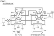
- Fig. 3 shows the second form of the flow path.
- Fig. 4 shows the third form of the flow path.
- Fig. 5 shows the fourth form of the flow path. Two positions of each of first switch valve 510 and second switch valve 520 and the four forms of the flow path will be described below with reference to Figs. 2 to 5 .
- first switch valve 510 The two positions of first switch valve 510 are referred to as position 0 and position 1.
- the positions of first switch valve 510 are additionally indicated in Figs. 2 to 5 .
- Position 0 of first switch valve 510 is shown in, for example, Fig. 2 . At this position, port 511 is coupled to port 512, port 513 is coupled to port 514, and port 515 is coupled to port 516.
- Position 1 of first switch valve 510 is shown in, for example, Fig. 4 . At this position, port 511 is coupled to port 516, port 513 is coupled to port 512, and port 515 is coupled to port 514.
- the two positions of second switch valve 520 are referred to as position 0 and position 1.
- the positions of second switch valve 520 are added in Figs. 2 to 5 .
- Position 0 of second switch valve 520 is shown in, for example, Fig. 2 . At this position, port 521 is coupled to port 522, port 523 is coupled to port 524, and port 525 is coupled to port 526.
- Position 1 of second switch valve 520 is shown in, for example, Fig. 3 . At this position, port 521 is coupled to port 526, port 523 is coupled to port 522, and port 525 is coupled to port 524.
- first switch valve 510 and second switch valve 520 In the first form, the position of each of first switch valve 510 and second switch valve 520 is "position 0" as shown in Fig. 2 .
- the mobile phase introduced from liquid feeding unit 200 into port 516 of first switch valve 510 is fed to detector 600 via port 515, port 526, port 525, end 411, end 412, port 521, port 522, port 514, port 513, end 421, end 422, port 511, port 512, port 523, and port 524.
- the mobile phase flows through first separation column 410 and second separation column 420 in the forward direction as indicated by an arrow A10.
- first switch valve 510 is "position 0"
- second switch valve 520 is "position 1" as shown in Fig. 3 .
- the mobile phase introduced from liquid feeding unit 200 into port 516 of first switch valve 510 is fed to detector 600 via port 515, port 526, port 521, end 412, end 411, port 525, and port 524.
- the mobile phase flows through first separation column 410 in the reverse direction as indicated by an arrow A20, but the mobile phase does not flow through second separation column 420 as schematically indicated by an icon P20.
- second separation column 420 is separated from the flow path in the second form.
- first switch valve 510 is "position 1"
- second switch valve 520 is "position 0" as shown in Fig. 4 .
- the mobile phase introduced from liquid feeding unit 200 to port 516 of first switch valve 510 is fed to detector 600 via port 511, end 422, end 421, port 513, port 512, port 523, and port 524.
- the mobile phase flows through second separation column 420 in the reverse direction as indicated by an arrow A30, but the mobile phase does not flow through first separation column 410 as schematically indicated by an icon P30.
- first separation column 410 is separated from the flow path in the third form.
- each of first switch valve 510 and second switch valve 520 is "position 1" as shown in Fig. 5 .
- the mobile phase introduced from liquid feeding unit 200 to port 516 of first switch valve 510 is fed to detector 600 via port 511, end 422, end 421, port 513, port 512, port 523, port 522, port 514, port 515, port 526, port 521, end 412, end 411, port 525, and port 524.
- the mobile phase flows through first separation column 410 and second separation column 420 in the reverse direction as indicated by an arrow A40.
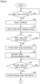
- Figs. 6 and 7 show a flowchart of a process performed by liquid chromatograph 1 for analysis of SARA components.
- processor 101 executes a given program, the process of Figs. 6 and 7 is performed in liquid chromatograph 1.
- liquid chromatograph 1 first determines whether a timing for starting analysis of SARA components has arrived. In response to a given operation having been performed on an operation key (not shown) of liquid chromatograph 1, in response to liquid chromatograph 1 externally having received an instruction to start an analysis, and/or upon arrival of a pre-registered time, liquid chromatograph 1 may determine that the above-mentioned timing has arrived.
- Liquid chromatograph 1 repeats the control of step S02 until determining that the above-mentioned timing has arrived (NO at step S02), and when determining that the above-mentioned timing has arrived (YES at step S02), moves the control to step S04.
- liquid chromatograph 1 causes sampler 300 to inject the sample (e.g., a sample for analysis of SARA components) into the flow path including first switch valve 510 and second switch valve 520.
- sampler 300 injects the sample (e.g., a sample for analysis of SARA components) into the flow path including first switch valve 510 and second switch valve 520.
- liquid chromatograph 1 forms the first form ( Fig. 2 ) in the flow path including first switch valve 510 and second switch valve 520 and causes liquid feeding unit 200 to feed the first mobile phase toward first switch valve 510.
- the first form may be formed as controller 100 switches the position of each of first switch valve 510 and second switch valve 520 to "position 0".
- the first mobile phase may be fed as controller 100 causes liquid feeding unit 200 to couple liquid feed pump 201 to the above-mentioned outlet port.
- liquid chromatograph 1 determines whether a first analysis time has elapsed from start of feeding of the first mobile phase (step S10).
- the first analysis time is a predetermined time for an analysis of a saturate component among the SARA components.
- the first analysis time may be set by a user as appropriate.
- the information for identifying the first analysis time may be stored in storage device 102.
- Liquid chromatograph 1 repeats the control of step S12 until determining that the first analysis time has elapsed (NO at step S12), and when determining that the first analysis time has elapsed (YES at step S12), moves the control to step S14.
- liquid chromatograph 1 stores, in storage device 102, a detection result (first analysis result) obtained by detector 600.
- the first analysis result includes an analysis result of the saturate component in the sample.
- liquid chromatograph 1 forms the second form ( Fig. 3 ) in the flow path including first switch valve 510 and second switch valve 520 and causes liquid feeding unit 200 to feed the second mobile phase toward first switch valve 510.
- the second form may be formed as controller 100 switches the position of first switch valve 510 to "position 0" and switches the position of second switch valve 520 to "position 1".
- the second mobile phase may be fed as controller 100 causes liquid feeding unit 200 to couple liquid feed pump 202 to the above-mentioned outlet port.
- liquid chromatograph 1 determines whether a second analysis time has elapsed from start of feeding of the second mobile phase (step S20).
- the second analysis time is a predetermined time for an analysis of a resin component among the SARA components.
- the second analysis time may be set by a user as appropriate.
- the information for identifying the second analysis time may be stored in storage device 102.
- Liquid chromatograph 1 repeats the control of step S22 until determining that the second analysis time has elapsed (NO at step S22), and when determining that the second analysis time has elapsed (YES at step S22), moves the control to step S24.
- liquid chromatograph 1 stores, in storage device 102, a detection result (second analysis result) obtained by detector 600.
- the second analysis result includes an analysis result of the resin component in the sample.
- liquid chromatograph 1 forms the second form ( Fig. 3 ) in the flow path including first switch valve 510 and second switch valve 520 and causes liquid feeding unit 200 to feed the third mobile phase toward first switch valve 510.
- the third mobile phase may be fed as controller 100 causes liquid feeding unit 200 to couple liquid feed pump 203 to the above-mentioned outlet port.
- liquid chromatograph 1 determines whether a third analysis time has elapsed from start of feeding of the third mobile phase (step S30).
- the third analysis time is a predetermined time for an analysis of an asphaltene component among the SARA components.
- the third analysis time may be set by a user as appropriate.
- the information for identifying the third analysis time may be stored in storage device 102.
- Liquid chromatograph 1 repeats the control of step S32 until determining that the third analysis time has elapsed (NO at step S32), and when determining that the third analysis time has elapsed (YES at step S32), moves the control to step S34.
- liquid chromatograph 1 stores, in storage device 102, a detection result (third analysis result) obtained by detector 600.
- the third analysis result includes an analysis result of the asphaltene component in the sample.
- liquid chromatograph 1 forms the third form ( Fig. 4 ) in the flow path including first switch valve 510 and second switch valve 520 and causes liquid feeding unit 200 to feed the fourth mobile phase toward first switch valve 510.
- the third form may be formed as controller 100 switches the position of first switch valve 510 to "position 1" and switches the position of second switch valve 520 to "position 0".
- the fourth mobile phase may be fed as controller 100 causes liquid feeding unit 200 to couple liquid feed pump 204 to the above-mentioned outlet port.
- liquid chromatograph 1 determines whether a fourth analysis time has elapsed from start of feeding of the fourth mobile phase (step S40).
- the fourth analysis time is a predetermined time for an analysis of an aromatic component among the SARA components.
- the fourth analysis time may be set by a user as appropriate.
- the information for identifying the fourth analysis time may be stored in storage device 102.
- Liquid chromatograph 1 repeats the control of step S42 until determining that the fourth analysis time has elapsed (NO at step S42), and when determining that the fourth analysis time has elapsed (YES at step S42), moves the control to step S44.
- liquid chromatograph 1 stores, in storage device 102, a detection result (fourth analysis result) obtained by detector 600.
- the fourth analysis result includes an analysis result of the aromatic component in the sample.
- liquid chromatograph 1 forms the fourth form ( Fig. 5 ) in the flow path including first switch valve 510 and second switch valve 520 and causes liquid feeding unit 200 to feed the cleaning liquid toward first switch valve 510.
- the fourth form may be formed as controller 100 switches the position of each of first switch valve 510 and second switch valve 520 to "position 1".
- the cleaning liquid may be fed as controller 100 causes liquid feeding unit 200 to couple liquid feed pump 205 to the above-mentioned outlet port.
- liquid chromatograph 1 determines whether a cleaning time has elapsed from start of feeding of the cleaning liquid (step S50).
- the cleaning time is a predetermined time for cleaning first separation column 410 and second separation column 420.
- the cleaning time may be set by a user as appropriate.
- the information for identifying the cleaning time may be stored in storage device 102.
- Liquid chromatograph 1 repeats the control of step S52 until determining that the cleaning time has elapsed (NO at step S52), and when determining that the cleaning time has elapsed (YES at S52), moves the control to step S54.
- liquid chromatograph 1 stops the operation of each element. Then, liquid chromatograph 1 ends the process of Figs. 6 and 7 .
- controller 100 combines two states of each of first switch valve 510 and second switch valve 520 to form the first to third forms in the flow path including first switch valve 510 and second switch valve 520, thereby providing SARA analysis using first separation column 410 and second separation column 420 in liquid chromatograph 1.
- second separation column 420 is separated from the flow path.
- first separation column 410 is separated from the flow path.
- the other separation column is separated from the flow path.
- contamination can be prevented, and premature deterioration of the separation column due to pressure fluctuations can be prevented.
- liquid chromatograph 1 In liquid chromatograph 1, the use of a backflow check valve is not required for formation of the first to third forms. This can reduce a system capacity and carry-over in liquid chromatograph 1.
- Controller 100 further forms the fourth form in the flow path and cleans first separation column 410 and second separation column 420 (steps S50, S52).
- the solution introduced from liquid feeding unit 200 flows through first separation column 410 and second separation column 420 in the reverse direction.
- cleaning at steps S50, S52 thus, the cleaning liquid flows through first separation column 410 and second separation column 420 in the reverse direction.
- the entire flow path is cleaned by backflash, thus reducing cross-contamination between analyses.
- cleaning using the first to fourth mobile phases used in the analyses of four components may be performed.
- liquid chromatograph 1 may flow the fourth mobile phase through a third flow path, flow the third mobile phase through a second flow path, flow the second mobile phase through the second flow path, and flow the first mobile phase through a first flow path.
- the mobile phases used in the analyses of four components are flowed in the reverse order of analysis.
- Liquid chromatograph 1 may further perform cleaning of steps S50, S52 after the cleaning using the first to fourth mobile phases.
- a liquid chromatograph may include: a first column; a second column; a liquid feeding unit configured to feed a mobile phase to at least one of the first column and the second column; a first switch valve having at least two connection states; a second switch valve connected to the first switch valve and having at least two connection states; and a control unit configured to combine one of the at least two connection states of the first switch valve and one of the at least two connection states of the second switch valve to form a first form, a second form, and a third form in a flow path including the first switch valve and the second switch valve.
- the mobile phase from the liquid feeding unit may be fed in order of a first end of the first column, a second end of the first column, a first end of the second column, and a second end of the second column.
- the mobile phase from the liquid feeding unit may not be introduced into the first column, and the mobile phase from the liquid feeding unit may be fed from the second end of the second column to the first end of the second column.
- the mobile phase from the liquid feeding unit may be fed from the second end of the first column to the first end of the first column, and the mobile phase from the liquid feeding unit may not be introduced into the second column.
- the liquid chromatograph according to clause 1 provides a configuration of a liquid chromatograph that implements a method of analyzing SARA components.
- the at least two connection states of the first switch valve may include a first state and a second state.
- the liquid feeding unit may be coupled to the second switch valve, and the second switch valve may be coupled to the first end of the second column.
- the liquid feeding unit may be coupled to the second end of the second column, the at least two connection states of the second switch valve may include a third state and a fourth state.
- the third state the second end of the first column may be coupled to the first switch valve, and the second end of the first column may be coupled to the first switch valve.
- the first switch valve may be coupled to the second end of the second column.
- the control unit may be configured to bring the first switch valve into the first state and bring the second switch valve into the third state to form the first form, bring the first switch valve into the first state and bring the second switch valve into the fourth state to form the second form, and bring the first switch valve into the second state and bring the second switch valve into the third state to form the third form.
- the liquid chromatograph according to clause 2 provides specific states of the first switch valve and the second switch valve, thereby easily implementing a method of analyzing SARA components in the liquid chromatograph.
- the liquid feeding unit may be configured to selectively feed any one of a first mobile phase, a second mobile phase, a third mobile phase, and a fourth mobile phase toward the first switch valve as the mobile phase.
- the control unit may be configured to cause the liquid feeding unit to feed the first mobile phase toward the first switch valve when the first form is formed in the flow path, cause the liquid feeding unit to feed the second mobile phase toward the first switch valve when the second form is formed in the flow path, cause the liquid feeding unit to feed the third mobile phase toward the first switch valve when the second form is formed in the flow path, and cause the liquid feeding unit to feed the fourth mobile phase toward the first switch valve when the third form is formed in the flow path.
- the liquid chromatograph according to clause 3 feeds appropriate mobile phases to the first column and the second column in analysis of SARA components.
- the liquid chromatograph according to any one of clauses 1 to 3 may further include a detector configured to derive a detection result of components of a solution.
- the first switch valve may couple the second end of the second column to the first switch valve, and the second switch valve may introduce the solution introduced from the second end of the second column into the detector.
- the first switch valve may separate the second column from the liquid feeding unit, and the second switch valve may couple the first end of the second column to the detector.
- the first switch valve may couple the first end of the second column to the detector, and the second switch valve may separate the first column from the liquid feeding unit.
- the liquid chromatograph according to clause 4 prevents contamination and prevent premature deterioration of a column due to pressure fluctuations.
- control unit may be configured to combine one of the at least two connection states of the first switch valve and one of the at least two connection states of the second switch valve to further form a fourth form in the flow path.
- the mobile phase from the liquid feeding unit may be fed from the second end of the first column to the first end of the first column and fed from the second end of the second column to the first end of the second column.
- the liquid chromatograph according to clause 5 forms a flow of the mobile phase by which the first column and the second column are cleaned.
- control unit may be configured to cause the liquid feeding unit to feed a cleaning liquid toward the first switch valve when the fourth form is formed in the flow path.
- the liquid chromatograph according to clause 6 cleans the first column and the second column with the cleaning liquid.
- the liquid chromatograph according to any one of clauses 1 to 6 may further include a sampler provided between the liquid feeding unit and the first switch valve and configured to supply a sample toward the flow path.
- the liquid chromatograph according to clause 7 supplies the sample to the first column and the second column in analysis of SARA components.
- the flow path may be configured to feed the mobile phase fed from the liquid feeding unit to the first switch valve.
- the liquid chromatograph according to clause 8 needs no additional element (such as a valve) for feeding the mobile phase fed from the liquid feeding unit to the first switch valve in analysis of SARA components, thus avoiding an increase in the cost for manufacturing the liquid chromatograph.
- liquid chromatograph 100 controller; 200 liquid feeding unit; 300 sampler; 410 first separation column; 420 second separation column; 510 first switch valve; 520 second switch valve; 600 detector.
Landscapes
- Chemical & Material Sciences (AREA)
- Analytical Chemistry (AREA)
- Chemical Kinetics & Catalysis (AREA)
- Physics & Mathematics (AREA)
- Health & Medical Sciences (AREA)
- Life Sciences & Earth Sciences (AREA)
- Biochemistry (AREA)
- General Health & Medical Sciences (AREA)
- General Physics & Mathematics (AREA)
- Immunology (AREA)
- Pathology (AREA)
- Treatment Of Liquids With Adsorbents In General (AREA)
Abstract
Description
- The present disclosure relates to liquid chromatographs, and more particularly, to a liquid chromatograph including two separation columns.
- Various studies have conventionally been conducted on the analysis of saturate, aromatic, resin, and asphaltene (SARA) components of an oil composite such as crude oil. "SARA" components mean four components, that is, saturate, aromatic, resin, and asphaltene components. An analysis method using two separation columns is disclosed as an example analysis of SARA components (see K.K. (Adry) Bissada, Jingqiang Tan, Ewa Szymczyk, Mike Darnell, Mei, 'Group-type characterization of crude oil and bitumen. Part I: Enhanced separation and quantification of saturates, aromatics, resins and asphaltenes (SARA)', Organic Geochemistry, May 2016, Vol. 95, pp. 21-28 (NPTL 1)).
- NPL 1: K.K. (Adry) Bissada, Jingqiang Tan, Ewa Szymczyk, Mike Darnell, Mei, 'Group-type characterization of crude oil and bitumen. Part I: Enhanced separation and quantification of saturates, aromatics, resins and asphaltenes (SARA)', Organic Geochemistry, May 2016, Vol. 95, pp. 21-28
- In implementation of the method of analyzing SARA components, it is desired to specifically study a configuration of a liquid chromatograph.
- A liquid chromatograph according to an aspect of the present disclosure includes: a first column; a second column; a liquid feeding unit configured to feed a mobile phase to at least one of the first column and the second column; a first switch valve having at least two connection states; a second switch valve connected to the first switch valve and having at least two connection states; and a control unit configured to combine one of the at least two connection states of the first switch valve and one of the at least two connection states of the second switch valve to form a first form, a second form, and a third form in a flow path including the first switch valve and the second switch valve. In the first form, the mobile phase from the liquid feeding unit is fed in order of a first end of the first column, a second end of the first column, a first end of the second column, and a second end of the second column. In the second form, the mobile phase from the liquid feeding unit is not introduced into the first column, and the mobile phase from the liquid feeding unit is fed from the second end of the second column to the first end of the second column. In the third form, the mobile phase from the liquid feeding unit is fed from the second end of the first column to the first end of the first column, and the mobile phase from the liquid feeding unit is not introduced into the second column.
- The present disclosure provides a configuration of a liquid chromatograph that implements a method of analyzing SARA components.
-
-
Fig. 1 shows a configuration of a liquid chromatograph. -
Fig. 2 shows a first form of a flow path. -
Fig. 3 shows a second form of the flow path. -
Fig. 4 shows a third form of the flow path. -
Fig. 5 shows a fourth form of the flow path. -
Figs. 6 and7 show a flowchart of a process for analysis of SARA components. - A liquid chromatograph according to an embodiment of the present disclosure will be described below in detail with reference to the drawings. The same or corresponding parts in the drawings have the same reference characters allotted, and description thereof will not be repeated.
-
Fig. 1 shows a configuration of aliquid chromatograph 1. In an example implementation,liquid chromatograph 1 is used for analysis of SARA components. - As shown in
Fig. 1 ,liquid chromatograph 1 includes acontroller 100, aliquid feeding unit 200, asampler 300, afirst separation column 410, asecond separation column 420, afirst switch valve 510, asecond switch valve 520, and adetector 600. -
Controller 100 controls an operation ofliquid chromatograph 1.Controller 100 includes aprocessor 101, astorage device 102, and aninterface 103. In an example implementation, asprocessor 101 executes a program stored instorage device 102,controller 100 controls an operation ofliquid chromatograph 1.Processor 101 may execute a program stored in a storage medium detachable fromcontroller 100.Interface 103 is implemented by a communication interface (e.g., network card).Processor 101 communicates with another element (such as sampler 300) ofliquid chromatograph 1 and communicates with a device external toliquid chromatograph 1, viainterface 103. -
Liquid feeding unit 200 feeds a solution used as a mobile phase to a flow path for the mobile phase which includesfirst switch valve 510 andsecond switch valve 520. Thus, the mobile phase is supplied tofirst separation column 410 and/orsecond separation column 420. - More specifically,
liquid feeding unit 200 includes fiveliquid feed pumps 201 to 205 and aswitch unit 210. Each ofliquid feed pumps 201 to 204 is connected to a tank containing a corresponding one of four types of mobile phases used in the SARA analysis and feeds its corresponding mobile phase towardswitch unit 210. - The four types of mobile phases are composed of a first mobile phase (e.g., hexane), which is a mobile phase for extraction of a saturate component, a second mobile phase (e.g., a mixed solution of hexane (94%) and chloroform (6%)), which is a mobile phase for extraction of a resin component, a third mobile phase (e.g., a mixed solution of methanol (15%), acetone (15%), and chloroform (70%)), which is a mobile phase for extraction of an asphaltene component, and a fourth mobile phase (e.g., chloroform), which is a mobile phase for extraction of an aromatic component.
-
Liquid feed pump 205 is connected to a tank containing a cleaning liquid forfirst separation column 410 andsecond separation column 420 and feeds the cleaning liquid towardswitch unit 210. The cleaning liquid may be the first mobile phase, the second mobile phase, the third mobile phase, and/or the fourth mobile phase described above. In this case,liquid feed pump 205 may not be included inliquid chromatograph 1. - Switch
unit 210 switches a pump that feeds a mobile phase towardfirst switch valve 510 from amongliquid feed pumps 201 to 205. In an example implementation,switch unit 210 includes five introduction ports each connected to a corresponding one ofliquid feed pumps 201 to 205, five solenoid valves each provided in a corresponding one of the five introduction ports, and one outlet port coupled tosampler 300. Switchunit 210 switches opening/closing of each of the five solenoid valves to couple part of the five introduction ports to the one outlet port, thereby switching the pump. - Sampler 300 supplies an analysis sample toward the flow path. In the example of
Fig. 1 ,sampler 300 is directly coupled to aport 516 offirst switch valve 510. In other words, the flow path includingfirst switch valve 510 andsecond switch valve 520 is configured to feed the mobile phase, fed from the liquid feeding unit, via (a sample introduction part of)sampler 300 tofirst switch valve 510. In analyzing the SARA components, thus,liquid chromatograph 1 requires no additional element (such as a switch valve) for feeding the sample and the mobile phase tofirst switch valve 510 in a portion of the flow path which extends fromsampler 300 tofirst switch valve 510. This avoids an increase in the cost for manufacturingliquid chromatograph 1 that analyzes SARA components. - Each of
first separation column 410 andsecond separation column 420 is supplied with the sample as well as the mobile phase, thereby separating target components included in the sample. Each offirst separation column 410 andsecond separation column 420 is housed in a column oven (not shown) and is maintained in the column oven at a temperature set by an analysis method. - The opposite ends of
first separation column 410 are illustrated as anend 411 and anend 412. Infirst separation column 410, a flow fromend 411 toend 412 is referred to as a flow in the "forward direction". A flow fromend 412 toend 411 is referred to as a flow in the "reverse direction" (backflash). - The opposite ends of
second separation column 420 are illustrated as anend 421 and anend 422. Insecond separation column 420, a flow fromend 421 toend 422 is referred to as a flow in the "forward direction". A flow fromend 422 toend 421 is referred to as a flow in the "reverse direction" (backflash). - When
liquid chromatograph 1 is used for analysis of SARA components, alkyl nitrile may be used as a filler offirst separation column 410. In other words, a cyano column may be used asfirst separation column 410. Silica may be used as a filler ofsecond separation column 420. In other words, a silica column may be used assecond separation column 420. -
Detector 600 analyzes a sample supplied fromfirst separation column 410 and/orsecond separation column 420.Detector 600 is implemented by, for example, an ultraviolet-visible spectrophotometer, a diode array detector, and/or a differential refractive index detector. - Each of
first switch valve 510 andsecond switch valve 520 is implemented by, for example, a 6-port, 2-position switch valve.First switch valve 510 includes sixports 511 to 516.Second switch valve 520 includes sixports 521 to 526. -
First switch valve 510 is coupled tosecond separation column 420. More specifically,port 513 is coupled to end 421 ofsecond separation column 420.Port 511 is coupled to end 422 ofsecond separation column 420. -
Second switch valve 520 is coupled tofirst separation column 410. More specifically,port 525 is coupled to end 411 offirst separation column 410.Port 521 is coupled to end 412 offirst separation column 410. - In
liquid chromatograph 1, two positions of each offirst switch valve 510 andsecond switch valve 520 are combined to form four forms (first to fourth forms) in the flow path includingfirst switch valve 510 andsecond switch valve 520.Fig. 2 shows the first form of the flow path.Fig. 3 shows the second form of the flow path.Fig. 4 shows the third form of the flow path.Fig. 5 shows the fourth form of the flow path. Two positions of each offirst switch valve 510 andsecond switch valve 520 and the four forms of the flow path will be described below with reference toFigs. 2 to 5 . - The two positions of
first switch valve 510 are referred to as position 0 andposition 1. The positions offirst switch valve 510 are additionally indicated inFigs. 2 to 5 . - Position 0 of
first switch valve 510 is shown in, for example,Fig. 2 . At this position,port 511 is coupled toport 512,port 513 is coupled toport 514, andport 515 is coupled toport 516. -
Position 1 offirst switch valve 510 is shown in, for example,Fig. 4 . At this position,port 511 is coupled toport 516,port 513 is coupled toport 512, andport 515 is coupled toport 514. - The two positions of
second switch valve 520 are referred to as position 0 andposition 1. The positions ofsecond switch valve 520 are added inFigs. 2 to 5 . - Position 0 of
second switch valve 520 is shown in, for example,Fig. 2 . At this position,port 521 is coupled toport 522,port 523 is coupled toport 524, andport 525 is coupled toport 526. -
Position 1 ofsecond switch valve 520 is shown in, for example,Fig. 3 . At this position,port 521 is coupled toport 526,port 523 is coupled toport 522, andport 525 is coupled toport 524. - In the first form, the position of each of
first switch valve 510 andsecond switch valve 520 is "position 0" as shown inFig. 2 . - In the first form, the mobile phase introduced from
liquid feeding unit 200 intoport 516 offirst switch valve 510 is fed todetector 600 viaport 515,port 526,port 525,end 411,end 412,port 521,port 522,port 514,port 513,end 421,end 422,port 511,port 512,port 523, andport 524. In the first form, thus, the mobile phase flows throughfirst separation column 410 andsecond separation column 420 in the forward direction as indicated by an arrow A10. - In the second form, the position of
first switch valve 510 is "position 0", and the position ofsecond switch valve 520 is "position 1", as shown inFig. 3 . - In the second form, the mobile phase introduced from
liquid feeding unit 200 intoport 516 offirst switch valve 510 is fed todetector 600 viaport 515,port 526,port 521,end 412,end 411,port 525, andport 524. In the second form, thus, the mobile phase flows throughfirst separation column 410 in the reverse direction as indicated by an arrow A20, but the mobile phase does not flow throughsecond separation column 420 as schematically indicated by an icon P20. In other words,second separation column 420 is separated from the flow path in the second form. - In the third form, the position of
first switch valve 510 is "position 1", and the position ofsecond switch valve 520 is "position 0", as shown inFig. 4 . - In the third form, the mobile phase introduced from
liquid feeding unit 200 toport 516 offirst switch valve 510 is fed todetector 600 viaport 511,end 422,end 421,port 513,port 512,port 523, andport 524. In the third form, thus, the mobile phase flows throughsecond separation column 420 in the reverse direction as indicated by an arrow A30, but the mobile phase does not flow throughfirst separation column 410 as schematically indicated by an icon P30. In other words,first separation column 410 is separated from the flow path in the third form. - In the fourth form, the position of each of
first switch valve 510 andsecond switch valve 520 is "position 1" as shown inFig. 5 . - In the fourth form, the mobile phase introduced from
liquid feeding unit 200 toport 516 offirst switch valve 510 is fed todetector 600 viaport 511,end 422,end 421,port 513,port 512,port 523,port 522,port 514,port 515,port 526,port 521,end 412,end 411,port 525, andport 524. In the fourth form, thus, the mobile phase flows throughfirst separation column 410 andsecond separation column 420 in the reverse direction as indicated by an arrow A40. -
Figs. 6 and7 show a flowchart of a process performed byliquid chromatograph 1 for analysis of SARA components. In an example implementation, asprocessor 101 executes a given program, the process ofFigs. 6 and7 is performed inliquid chromatograph 1. - Referring to
Fig. 6 , at step S10,liquid chromatograph 1 first determines whether a timing for starting analysis of SARA components has arrived. In response to a given operation having been performed on an operation key (not shown) ofliquid chromatograph 1, in response toliquid chromatograph 1 externally having received an instruction to start an analysis, and/or upon arrival of a pre-registered time,liquid chromatograph 1 may determine that the above-mentioned timing has arrived. -
Liquid chromatograph 1 repeats the control of step S02 until determining that the above-mentioned timing has arrived (NO at step S02), and when determining that the above-mentioned timing has arrived (YES at step S02), moves the control to step S04. - At step S04,
liquid chromatograph 1 causessampler 300 to inject the sample (e.g., a sample for analysis of SARA components) into the flow path includingfirst switch valve 510 andsecond switch valve 520. - At step S10,
liquid chromatograph 1 forms the first form (Fig. 2 ) in the flow path includingfirst switch valve 510 andsecond switch valve 520 and causesliquid feeding unit 200 to feed the first mobile phase towardfirst switch valve 510. - The first form may be formed as
controller 100 switches the position of each offirst switch valve 510 andsecond switch valve 520 to "position 0". The first mobile phase may be fed ascontroller 100 causesliquid feeding unit 200 to coupleliquid feed pump 201 to the above-mentioned outlet port. - At step S12,
liquid chromatograph 1 determines whether a first analysis time has elapsed from start of feeding of the first mobile phase (step S10). The first analysis time is a predetermined time for an analysis of a saturate component among the SARA components. The first analysis time may be set by a user as appropriate. The information for identifying the first analysis time may be stored instorage device 102.Liquid chromatograph 1 repeats the control of step S12 until determining that the first analysis time has elapsed (NO at step S12), and when determining that the first analysis time has elapsed (YES at step S12), moves the control to step S14. - At step S14,
liquid chromatograph 1 stores, instorage device 102, a detection result (first analysis result) obtained bydetector 600. In an example implementation, the first analysis result includes an analysis result of the saturate component in the sample. - At step S20,
liquid chromatograph 1 forms the second form (Fig. 3 ) in the flow path includingfirst switch valve 510 andsecond switch valve 520 and causesliquid feeding unit 200 to feed the second mobile phase towardfirst switch valve 510. - The second form may be formed as
controller 100 switches the position offirst switch valve 510 to "position 0" and switches the position ofsecond switch valve 520 to "position 1". The second mobile phase may be fed ascontroller 100 causesliquid feeding unit 200 to coupleliquid feed pump 202 to the above-mentioned outlet port. - At step S22,
liquid chromatograph 1 determines whether a second analysis time has elapsed from start of feeding of the second mobile phase (step S20). The second analysis time is a predetermined time for an analysis of a resin component among the SARA components. The second analysis time may be set by a user as appropriate. The information for identifying the second analysis time may be stored instorage device 102.Liquid chromatograph 1 repeats the control of step S22 until determining that the second analysis time has elapsed (NO at step S22), and when determining that the second analysis time has elapsed (YES at step S22), moves the control to step S24. - At step S24,
liquid chromatograph 1 stores, instorage device 102, a detection result (second analysis result) obtained bydetector 600. In an example implementation, the second analysis result includes an analysis result of the resin component in the sample. - Referring to
Fig. 7 , at step S30,liquid chromatograph 1 forms the second form (Fig. 3 ) in the flow path includingfirst switch valve 510 andsecond switch valve 520 and causesliquid feeding unit 200 to feed the third mobile phase towardfirst switch valve 510. - The third mobile phase may be fed as
controller 100 causesliquid feeding unit 200 to coupleliquid feed pump 203 to the above-mentioned outlet port. - At step S32,
liquid chromatograph 1 determines whether a third analysis time has elapsed from start of feeding of the third mobile phase (step S30). The third analysis time is a predetermined time for an analysis of an asphaltene component among the SARA components. The third analysis time may be set by a user as appropriate. The information for identifying the third analysis time may be stored instorage device 102.Liquid chromatograph 1 repeats the control of step S32 until determining that the third analysis time has elapsed (NO at step S32), and when determining that the third analysis time has elapsed (YES at step S32), moves the control to step S34. - At step S34,
liquid chromatograph 1 stores, instorage device 102, a detection result (third analysis result) obtained bydetector 600. In an example implementation, the third analysis result includes an analysis result of the asphaltene component in the sample. - At step S40,
liquid chromatograph 1 forms the third form (Fig. 4 ) in the flow path includingfirst switch valve 510 andsecond switch valve 520 and causesliquid feeding unit 200 to feed the fourth mobile phase towardfirst switch valve 510. - The third form may be formed as
controller 100 switches the position offirst switch valve 510 to "position 1" and switches the position ofsecond switch valve 520 to "position 0". The fourth mobile phase may be fed ascontroller 100 causesliquid feeding unit 200 to coupleliquid feed pump 204 to the above-mentioned outlet port. - At step S42,
liquid chromatograph 1 determines whether a fourth analysis time has elapsed from start of feeding of the fourth mobile phase (step S40). The fourth analysis time is a predetermined time for an analysis of an aromatic component among the SARA components. The fourth analysis time may be set by a user as appropriate. The information for identifying the fourth analysis time may be stored instorage device 102.Liquid chromatograph 1 repeats the control of step S42 until determining that the fourth analysis time has elapsed (NO at step S42), and when determining that the fourth analysis time has elapsed (YES at step S42), moves the control to step S44. - At step S44,
liquid chromatograph 1 stores, instorage device 102, a detection result (fourth analysis result) obtained bydetector 600. In an example implementation, the fourth analysis result includes an analysis result of the aromatic component in the sample. - At step S50,
liquid chromatograph 1 forms the fourth form (Fig. 5 ) in the flow path includingfirst switch valve 510 andsecond switch valve 520 and causesliquid feeding unit 200 to feed the cleaning liquid towardfirst switch valve 510. - The fourth form may be formed as
controller 100 switches the position of each offirst switch valve 510 andsecond switch valve 520 to "position 1". The cleaning liquid may be fed ascontroller 100 causesliquid feeding unit 200 to coupleliquid feed pump 205 to the above-mentioned outlet port. - At step S52,
liquid chromatograph 1 determines whether a cleaning time has elapsed from start of feeding of the cleaning liquid (step S50). The cleaning time is a predetermined time for cleaningfirst separation column 410 andsecond separation column 420. The cleaning time may be set by a user as appropriate. The information for identifying the cleaning time may be stored instorage device 102.Liquid chromatograph 1 repeats the control of step S52 until determining that the cleaning time has elapsed (NO at step S52), and when determining that the cleaning time has elapsed (YES at S52), moves the control to step S54. - At step S60,
liquid chromatograph 1 stops the operation of each element. Then,liquid chromatograph 1 ends the process ofFigs. 6 and7 . - In
liquid chromatograph 1 described above,controller 100 combines two states of each offirst switch valve 510 andsecond switch valve 520 to form the first to third forms in the flow path includingfirst switch valve 510 andsecond switch valve 520, thereby providing SARA analysis usingfirst separation column 410 andsecond separation column 420 inliquid chromatograph 1. - In the second form,
second separation column 420 is separated from the flow path. In the third form,first separation column 410 is separated from the flow path. In other words, during backflash of one of two separation columns, the other separation column is separated from the flow path. Inliquid chromatograph 1, contamination can be prevented, and premature deterioration of the separation column due to pressure fluctuations can be prevented. - In
liquid chromatograph 1, the use of a backflow check valve is not required for formation of the first to third forms. This can reduce a system capacity and carry-over inliquid chromatograph 1. -
Controller 100 further forms the fourth form in the flow path and cleansfirst separation column 410 and second separation column 420 (steps S50, S52). - In the fourth form, the solution introduced from
liquid feeding unit 200 flows throughfirst separation column 410 andsecond separation column 420 in the reverse direction. In cleaning at steps S50, S52, thus, the cleaning liquid flows throughfirst separation column 410 andsecond separation column 420 in the reverse direction. In the fourth form, the entire flow path is cleaned by backflash, thus reducing cross-contamination between analyses. - In place of cleaning at steps S50, S52, or in addition to cleaning at steps S50, S52, cleaning using the first to fourth mobile phases used in the analyses of four components may be performed.
- For example, after step S44,
liquid chromatograph 1 may flow the fourth mobile phase through a third flow path, flow the third mobile phase through a second flow path, flow the second mobile phase through the second flow path, and flow the first mobile phase through a first flow path. Thus, after the analyses of four components, the mobile phases used in the analyses of four components are flowed in the reverse order of analysis.Liquid chromatograph 1 may further perform cleaning of steps S50, S52 after the cleaning using the first to fourth mobile phases. - A person skilled in the art will understand that the illustrative embodiments described above are specific examples of the following aspect.
- (Clause 1) A liquid chromatograph according to an aspect may include: a first column; a second column; a liquid feeding unit configured to feed a mobile phase to at least one of the first column and the second column; a first switch valve having at least two connection states; a second switch valve connected to the first switch valve and having at least two connection states; and a control unit configured to combine one of the at least two connection states of the first switch valve and one of the at least two connection states of the second switch valve to form a first form, a second form, and a third form in a flow path including the first switch valve and the second switch valve. In the first form, the mobile phase from the liquid feeding unit may be fed in order of a first end of the first column, a second end of the first column, a first end of the second column, and a second end of the second column. In the second form, the mobile phase from the liquid feeding unit may not be introduced into the first column, and the mobile phase from the liquid feeding unit may be fed from the second end of the second column to the first end of the second column. In the third form, the mobile phase from the liquid feeding unit may be fed from the second end of the first column to the first end of the first column, and the mobile phase from the liquid feeding unit may not be introduced into the second column.
- The liquid chromatograph according to
clause 1 provides a configuration of a liquid chromatograph that implements a method of analyzing SARA components. - (Clause 2) In the liquid chromatograph according to
clause 1, the at least two connection states of the first switch valve may include a first state and a second state. In the first state, the liquid feeding unit may be coupled to the second switch valve, and the second switch valve may be coupled to the first end of the second column. In the second state, the liquid feeding unit may be coupled to the second end of the second column, the at least two connection states of the second switch valve may include a third state and a fourth state. In the third state, the second end of the first column may be coupled to the first switch valve, and the second end of the first column may be coupled to the first switch valve. In the fourth state, the first switch valve may be coupled to the second end of the second column. The control unit may be configured to bring the first switch valve into the first state and bring the second switch valve into the third state to form the first form, bring the first switch valve into the first state and bring the second switch valve into the fourth state to form the second form, and bring the first switch valve into the second state and bring the second switch valve into the third state to form the third form. - The liquid chromatograph according to clause 2 provides specific states of the first switch valve and the second switch valve, thereby easily implementing a method of analyzing SARA components in the liquid chromatograph.
- (Clause 3) In the liquid chromatograph according to
clause 1 or 2, the liquid feeding unit may be configured to selectively feed any one of a first mobile phase, a second mobile phase, a third mobile phase, and a fourth mobile phase toward the first switch valve as the mobile phase. The control unit may be configured to cause the liquid feeding unit to feed the first mobile phase toward the first switch valve when the first form is formed in the flow path, cause the liquid feeding unit to feed the second mobile phase toward the first switch valve when the second form is formed in the flow path, cause the liquid feeding unit to feed the third mobile phase toward the first switch valve when the second form is formed in the flow path, and cause the liquid feeding unit to feed the fourth mobile phase toward the first switch valve when the third form is formed in the flow path. - The liquid chromatograph according to clause 3 feeds appropriate mobile phases to the first column and the second column in analysis of SARA components.
- (Clause 4) The liquid chromatograph according to any one of
clauses 1 to 3 may further include a detector configured to derive a detection result of components of a solution. In the first form, the first switch valve may couple the second end of the second column to the first switch valve, and the second switch valve may introduce the solution introduced from the second end of the second column into the detector. In the second form, the first switch valve may separate the second column from the liquid feeding unit, and the second switch valve may couple the first end of the second column to the detector. In the third form, the first switch valve may couple the first end of the second column to the detector, and the second switch valve may separate the first column from the liquid feeding unit. - The liquid chromatograph according to clause 4 prevents contamination and prevent premature deterioration of a column due to pressure fluctuations.
- (Clause 5) In the liquid chromatograph according to any one of
clauses 1 to 4, the control unit may be configured to combine one of the at least two connection states of the first switch valve and one of the at least two connection states of the second switch valve to further form a fourth form in the flow path. In the fourth form, the mobile phase from the liquid feeding unit may be fed from the second end of the first column to the first end of the first column and fed from the second end of the second column to the first end of the second column. - The liquid chromatograph according to clause 5 forms a flow of the mobile phase by which the first column and the second column are cleaned.
- (Clause 6) In the liquid chromatograph according to clause 5, the control unit may be configured to cause the liquid feeding unit to feed a cleaning liquid toward the first switch valve when the fourth form is formed in the flow path.
- The liquid chromatograph according to clause 6 cleans the first column and the second column with the cleaning liquid.
- (Clause 7) The liquid chromatograph according to any one of
clauses 1 to 6 may further include a sampler provided between the liquid feeding unit and the first switch valve and configured to supply a sample toward the flow path. - The liquid chromatograph according to clause 7 supplies the sample to the first column and the second column in analysis of SARA components.
- (Clause 8) In the liquid chromatograph according to any one of
clauses 1 to 7, the flow path may be configured to feed the mobile phase fed from the liquid feeding unit to the first switch valve. - The liquid chromatograph according to clause 8 needs no additional element (such as a valve) for feeding the mobile phase fed from the liquid feeding unit to the first switch valve in analysis of SARA components, thus avoiding an increase in the cost for manufacturing the liquid chromatograph.
- It should be appreciated that the embodiments disclosed herein are illustrative in every sense and are not limitative. The scope of the present disclosure is defined by the terms of the claims, rather than the embodiments described above, and is intended to include any modifications within the scope and meaning equivalent to the terms of the claims.
- 1 liquid chromatograph; 100 controller; 200 liquid feeding unit; 300 sampler; 410 first separation column; 420 second separation column; 510 first switch valve; 520 second switch valve; 600 detector.
Claims (8)
- A liquid chromatograph comprising:a first column;a second column;a liquid feeding unit configured to feed a mobile phase to at least one of the first column and the second column;a first switch valve having at least two connection states;a second switch valve connected to the first switch valve and having at least two connection states; anda control unit configured to combine one of the at least two connection states of the first switch valve and one of the at least two connection states of the second switch valve to form a first form, a second form, and a third form in a flow path including the first switch valve and the second switch valve, whereinin the first form, the mobile phase from the liquid feeding unit is fed in order of a first end of the first column, a second end of the first column, a first end of the second column, and a second end of the second column,in the second form, the mobile phase from the liquid feeding unit is not introduced into the first column, and the mobile phase from the liquid feeding unit is fed from the second end of the second column to the first end of the second column, andin the third form, the mobile phase from the liquid feeding unit is fed from the second end of the first column to the first end of the first column, and the mobile phase from the liquid feeding unit is not introduced into the second column.
- The liquid chromatograph according to claim 1, whereinthe at least two connection states of the first switch valve include a first state and a second state,in the first state, the liquid feeding unit is coupled to the second switch valve, and the second switch valve is coupled to the first end of the second column,in the second state, the liquid feeding unit is coupled to the second end of the second column,the at least two connection states of the second switch valve include a third state and a fourth state,in the third state, the second end of the first column is coupled to the first switch valve, and the second end of the first column is coupled to the first switch valve,in the fourth state, the first switch valve is coupled to the second end of the second column, andthe control unit is configured tobring the first switch valve into the first state and bring the second switch valve into the third state to form the first form,bring the first switch valve into the first state and bring the second switch valve into the fourth state to form the second form, andbring the first switch valve into the second state and bring the second switch valve into the third state to form the third form.
- The liquid chromatograph according to claim 1, whereinthe liquid feeding unit is configured to selectively feed any one of a first mobile phase, a second mobile phase, a third mobile phase, and a fourth mobile phase toward the first switch valve as the mobile phase, andthe control unit is configured tocause the liquid feeding unit to feed the first mobile phase toward the first switch valve when the first form is formed in the flow path,cause the liquid feeding unit to feed the second mobile phase toward the first switch valve when the second form is formed in the flow path,cause the liquid feeding unit to feed the third mobile phase toward the first switch valve when the second form is formed in the flow path, andcause the liquid feeding unit to feed the fourth mobile phase toward the first switch valve when the third form is formed in the flow path.
- The liquid chromatograph according to claim 1, further comprising a detector configured to derive a detection result of components of a solution, whereinin the first form,the first switch valve couples the second end of the second column to the first switch valve, andthe second switch valve introduces the solution introduced from the second end of the second column into the detector,in the second form,the first switch valve separates the second column from the liquid feeding unit, andthe second switch valve couples the first end of the second column to the detector, andin the third form,the first switch valve couples the first end of the second column to the detector, andthe second switch valve separates the first column from the liquid feeding unit.
- The liquid chromatograph according to claim 1, whereinthe control unit is configured to combine one of the at least two connection states of the first switch valve and one of the at least two connection states of the second switch valve to further form a fourth form in the flow path, andin the fourth form, the mobile phase from the liquid feeding unit is fed from the second end of the first column to the first end of the first column and fed from the second end of the second column to the first end of the second column.
- The liquid chromatograph according to claim 5, wherein the control unit is configured to cause the liquid feeding unit to feed a cleaning liquid toward the first switch valve when the fourth form is formed in the flow path.
- The liquid chromatograph according to claim 1, further comprising a sampler provided between the liquid feeding unit and the first switch valve and configured to supply a sample toward the flow path.
- The liquid chromatograph according to claim 1, wherein the flow path is configured to feed the mobile phase fed from the liquid feeding unit to the first switch valve.
Applications Claiming Priority (2)
| Application Number | Priority Date | Filing Date | Title |
|---|---|---|---|
| SG10202114207R | 2021-12-21 | ||
| PCT/JP2022/042254 WO2023119944A1 (en) | 2021-12-21 | 2022-11-14 | Liquid chromatograph |
Publications (2)
| Publication Number | Publication Date |
|---|---|
| EP4455659A1 true EP4455659A1 (en) | 2024-10-30 |
| EP4455659A4 EP4455659A4 (en) | 2025-12-10 |
Family
ID=86902209
Family Applications (1)
| Application Number | Title | Priority Date | Filing Date |
|---|---|---|---|
| EP22910663.8A Pending EP4455659A4 (en) | 2021-12-21 | 2022-11-14 | LIQUID ROMOTOGRAPH |
Country Status (4)
| Country | Link |
|---|---|
| US (1) | US20250020618A1 (en) |
| EP (1) | EP4455659A4 (en) |
| JP (1) | JP7841545B2 (en) |
| WO (1) | WO2023119944A1 (en) |
Families Citing this family (1)
| Publication number | Priority date | Publication date | Assignee | Title |
|---|---|---|---|---|
| JP2024152467A (en) * | 2023-04-14 | 2024-10-25 | 株式会社島津製作所 | Analytical Equipment |
Family Cites Families (8)
| Publication number | Priority date | Publication date | Assignee | Title |
|---|---|---|---|---|
| JPS58146852A (en) * | 1982-02-26 | 1983-09-01 | Toyo Soda Mfg Co Ltd | Liquid chromatography |
| JPS63135855A (en) * | 1986-11-27 | 1988-06-08 | Shimadzu Corp | Anion analyzer |
| JPH04116459A (en) * | 1990-09-07 | 1992-04-16 | Sekisui Chem Co Ltd | Apparatus and method for analyzing albumin |
| DK172622B1 (en) * | 1992-01-22 | 1999-03-08 | Slagteriernes Forskningsinst | Method for determining the content of at least one fat-soluble compound in individual subjects, apparatus for use in |
| JPH0694697A (en) * | 1992-09-08 | 1994-04-08 | Cosmo Sogo Kenkyusho:Kk | Analytical method and device classified by hydrocarbon type of hydrocarbon oil |
| JPH07229885A (en) * | 1994-02-16 | 1995-08-29 | Takeda Chem Ind Ltd | Automatic separator of sample |
| DE102005025440B4 (en) * | 2005-06-02 | 2018-04-05 | Waters Gmbh | System and method for sample preparation |
| CN108562678B (en) | 2018-02-12 | 2023-09-22 | 大连博迈科技发展有限公司 | Three-dimensional liquid chromatographic separation system based on full online detection of same detector |
-
2022
- 2022-11-14 WO PCT/JP2022/042254 patent/WO2023119944A1/en not_active Ceased
- 2022-11-14 JP JP2023569157A patent/JP7841545B2/en active Active
- 2022-11-14 US US18/711,498 patent/US20250020618A1/en active Pending
- 2022-11-14 EP EP22910663.8A patent/EP4455659A4/en active Pending
Also Published As
| Publication number | Publication date |
|---|---|
| JPWO2023119944A1 (en) | 2023-06-29 |
| WO2023119944A1 (en) | 2023-06-29 |
| US20250020618A1 (en) | 2025-01-16 |
| EP4455659A4 (en) | 2025-12-10 |
| JP7841545B2 (en) | 2026-04-07 |
Similar Documents
| Publication | Publication Date | Title |
|---|---|---|
| EP1457774B1 (en) | Separation analyser | |
| US11692980B2 (en) | Valve and splitting system for multi-dimensional liquid analysis | |
| EP4455659A1 (en) | Liquid chromatograph | |
| US20140014585A1 (en) | Chromatographic interface | |
| EP4187243A1 (en) | Method and apparatus for injecting a chromatographic sample | |
| US10802001B2 (en) | Online dilution for a liquid chromatography system using a sample metering pump | |
| WO2010118414A1 (en) | Apparatus and method for coupled lc-nmr analysis | |
| US11079360B2 (en) | Systems and methods for chromatographic analysis | |
| US20200025723A1 (en) | Dispersive element in liquid chromatography systems | |
| US12111297B2 (en) | Liquid chromatograph and analysis method using liquid chromatograph | |
| US6237396B1 (en) | Integrated analysis process and device for hydrocarbon characterization by distillation simulation | |
| US20240060939A1 (en) | Sample metering and injection for liquid chromatography | |
| US20150346166A1 (en) | Sample concentration device | |
| JP2023044723A (en) | Liquid chromatograph and flow channel cleaning method in liquid chromatograph | |
| US7958774B2 (en) | Device and method for sample preparation | |
| JP7259946B2 (en) | Liquid chromatograph | |
| JP2005128030A (en) | Liquid chromatograph | |
| CN116060343A (en) | Method for cleaning liquid chromatography system and liquid chromatography system | |
| US12222333B2 (en) | Preparative chromatograph and preparative method using preparative chromatograph | |
| US11185794B2 (en) | Method of fraction collection for a liquid chromatography system | |
| JPWO2009084235A1 (en) | Liquid chromatograph | |
| US20260110667A1 (en) | Preparative liquid chromatograph | |
| Rogatsky et al. | Flow inconsistency: The evil twin of column switching—Hardware aspects | |
| JP7517477B2 (en) | Preparative Liquid Chromatograph | |
| CN113316719B (en) | Liquid chromatography |
Legal Events
| Date | Code | Title | Description |
|---|---|---|---|
| STAA | Information on the status of an ep patent application or granted ep patent |
Free format text: STATUS: THE INTERNATIONAL PUBLICATION HAS BEEN MADE |
|
| PUAI | Public reference made under article 153(3) epc to a published international application that has entered the european phase |
Free format text: ORIGINAL CODE: 0009012 |
|
| STAA | Information on the status of an ep patent application or granted ep patent |
Free format text: STATUS: REQUEST FOR EXAMINATION WAS MADE |
|
| 17P | Request for examination filed |
Effective date: 20240502 |
|
| AK | Designated contracting states |
Kind code of ref document: A1 Designated state(s): AL AT BE BG CH CY CZ DE DK EE ES FI FR GB GR HR HU IE IS IT LI LT LU LV MC ME MK MT NL NO PL PT RO RS SE SI SK SM TR |
|
| DAV | Request for validation of the european patent (deleted) | ||
| DAX | Request for extension of the european patent (deleted) | ||
| A4 | Supplementary search report drawn up and despatched |
Effective date: 20251107 |
|
| RIC1 | Information provided on ipc code assigned before grant |
Ipc: G01N 30/26 20060101AFI20251103BHEP |