EP4455642A1 - Digital adaptive optical method and apparatus for multiphoton microscopy - Google Patents
Digital adaptive optical method and apparatus for multiphoton microscopy Download PDFInfo
- Publication number
- EP4455642A1 EP4455642A1 EP23853726.0A EP23853726A EP4455642A1 EP 4455642 A1 EP4455642 A1 EP 4455642A1 EP 23853726 A EP23853726 A EP 23853726A EP 4455642 A1 EP4455642 A1 EP 4455642A1
- Authority
- EP
- European Patent Office
- Prior art keywords
- imaging
- aberration
- aperture
- lateral shift
- photon
- Prior art date
- Legal status (The legal status is an assumption and is not a legal conclusion. Google has not performed a legal analysis and makes no representation as to the accuracy of the status listed.)
- Pending
Links
Images





Classifications
-
- G—PHYSICS
- G02—OPTICS
- G02B—OPTICAL ELEMENTS, SYSTEMS OR APPARATUS
- G02B27/00—Optical systems or apparatus not provided for by any of the groups G02B1/00 - G02B26/00, G02B30/00
- G02B27/0012—Optical design, e.g. procedures, algorithms, optimisation routines
-
- G—PHYSICS
- G02—OPTICS
- G02B—OPTICAL ELEMENTS, SYSTEMS OR APPARATUS
- G02B21/00—Microscopes
- G02B21/0004—Microscopes specially adapted for specific applications
- G02B21/002—Scanning microscopes
- G02B21/0024—Confocal scanning microscopes (CSOMs) or confocal "macroscopes"; Accessories which are not restricted to use with CSOMs, e.g. sample holders
- G02B21/0032—Optical details of illumination, e.g. light-sources, pinholes, beam splitters, slits, fibers
-
- G—PHYSICS
- G02—OPTICS
- G02B—OPTICAL ELEMENTS, SYSTEMS OR APPARATUS
- G02B21/00—Microscopes
- G02B21/0004—Microscopes specially adapted for specific applications
- G02B21/002—Scanning microscopes
- G02B21/0024—Confocal scanning microscopes (CSOMs) or confocal "macroscopes"; Accessories which are not restricted to use with CSOMs, e.g. sample holders
- G02B21/0052—Optical details of the image generation
- G02B21/0076—Optical details of the image generation arrangements using fluorescence or luminescence
-
- G—PHYSICS
- G02—OPTICS
- G02B—OPTICAL ELEMENTS, SYSTEMS OR APPARATUS
- G02B21/00—Microscopes
- G02B21/0004—Microscopes specially adapted for specific applications
- G02B21/002—Scanning microscopes
- G02B21/0024—Confocal scanning microscopes (CSOMs) or confocal "macroscopes"; Accessories which are not restricted to use with CSOMs, e.g. sample holders
- G02B21/008—Details of detection or image processing, including general computer control
-
- G—PHYSICS
- G02—OPTICS
- G02B—OPTICAL ELEMENTS, SYSTEMS OR APPARATUS
- G02B21/00—Microscopes
- G02B21/0004—Microscopes specially adapted for specific applications
- G02B21/002—Scanning microscopes
- G02B21/0024—Confocal scanning microscopes (CSOMs) or confocal "macroscopes"; Accessories which are not restricted to use with CSOMs, e.g. sample holders
- G02B21/0036—Scanning details, e.g. scanning stages
- G02B21/0048—Scanning details, e.g. scanning stages scanning mirrors, e.g. rotating or galvanomirrors, MEMS mirrors
-
- G—PHYSICS
- G02—OPTICS
- G02B—OPTICAL ELEMENTS, SYSTEMS OR APPARATUS
- G02B2207/00—Coding scheme for general features or characteristics of optical elements and systems of subclass G02B, but not including elements and systems which would be classified in G02B6/00 and subgroups
- G02B2207/114—Two photon or multiphoton effect
-
- G—PHYSICS
- G02—OPTICS
- G02B—OPTICAL ELEMENTS, SYSTEMS OR APPARATUS
- G02B2207/00—Coding scheme for general features or characteristics of optical elements and systems of subclass G02B, but not including elements and systems which would be classified in G02B6/00 and subgroups
- G02B2207/125—Wavefront coding
-
- G—PHYSICS
- G02—OPTICS
- G02F—OPTICAL DEVICES OR ARRANGEMENTS FOR THE CONTROL OF LIGHT BY MODIFICATION OF THE OPTICAL PROPERTIES OF THE MEDIA OF THE ELEMENTS INVOLVED THEREIN; NON-LINEAR OPTICS; FREQUENCY-CHANGING OF LIGHT; OPTICAL LOGIC ELEMENTS; OPTICAL ANALOGUE/DIGITAL CONVERTERS
- G02F2203/00—Function characteristic
- G02F2203/18—Function characteristic adaptive optics, e.g. wavefront correction
Definitions
- the present disclosure relates to the technical field of microscopy imaging, and particularly relates to a digital adaptive optics method and a device for multi-photon imaging.
- multi-photon microscopy is widely applied to increasing life science researches, has large penetration depth and high chromatographic capacity, and is applicable to imaging of deep scattering samples.
- the system aberration may be compensated through adaptive optics by measuring the aberration of the optical system during imaging.
- the present disclosure provides a digital adaptive optics method and a device for multi-photon imaging, for solving problems in related technologies that imaging velocity of the system is decreased since an imaging environment needs to be measured in advance before acquisition of an aberration phase, the wavefront aberration compensation process depends on an active optical device, complexity of the optical system is increased, high-quality multi-photon imaging cannot be quickly realized, imaging efficiency of the optical system is decreased and practicability is lower.
- Embodiments of the first aspect of the present disclosure provide a digital adaptive optics method for multi-photon imaging.
- the method includes the following steps: acquiring three-dimensional sample projection of different views based on a two-photon synthetic aperture microscopy by utilizing small-aperture excitation light beams constrained by a preset diffraction limit size aperture, and generating small-aperture imaging results of different views; calculating, based on the small-aperture imaging results, lateral shift vectors produced by images of different sub-apertures caused by wavefront aberration phases brought by system aberration or tissue scattering in the imaging process, and acquiring three-dimensional sample information that meets preset resolution conditions; and compensating optical aberration according to the lateral shift vectors in a process of obtaining three-dimensional reconstruction results based on the three-dimensional sample information.
- the compensating optical aberration according to the lateral shift vectors in the process of obtaining three-dimensional reconstruction results based on the three-dimensional sample information includes: applying the wavefront aberration phases determined by the lateral shift vectors to generation of a system point spread function in a preset three-dimensional reconstruction algorithm.
- the compensating optical aberration according to the lateral shift vectors in the process of obtaining three-dimensional reconstruction results based on the three-dimensional sample information includes: compensating the lateral shift vectors in the preset three-dimensional reconstruction algorithm, and then performing the three-dimensional reconstruction.
- Embodiments of the second aspect of the present disclosure provide a digital adaptive optics device for multi-photon imaging.
- the device includes: an acquiring module configured to acquire three-dimensional sample projection of different views based on a two-photon synthetic aperture microscopy by utilizing small-aperture excitation light beams constrained by a preset diffraction limit size aperture, and generate small-aperture imaging results of different views; a calculating module configured to calculate, based on the small-aperture imaging results, lateral shift vectors produced by images of different sub-apertures caused by wavefront aberration phases brought by system aberration or tissue scattering in an imaging process, and acquire three-dimensional sample information that meets preset resolution conditions; and an imaging module configured to compensate optical aberration according to the lateral shift vectors in a process of obtaining three-dimensional reconstruction results based on the three-dimensional sample information.
- the imaging module includes: a correction unit configured to apply the wavefront aberration phases determined by the lateral shift vectors to generation of a system point spread function in a preset three-dimensional reconstruction algorithm.
- the imaging module includes: a compensating unit configured to compensate the lateral shift vectors in the preset three-dimensional reconstruction algorithm, and then perform the three-dimensional reconstruction.
- Embodiments of the third aspect of the present disclosure provide an electronic device.
- the electronic device includes a memory, a processor, and a computer program stored in the memory and executed in the processor.
- the processor executes the program to implement the digital adaptive optics method for multi-photon imaging in the above embodiments.
- Embodiments of the fourth aspect of the present disclosure provide a computer readable storage medium.
- a computer program is stored in the computer readable storage medium.
- the program is executed by a processor to implement the above digital adaptive optics method for multi-photon imaging.
- the optical aberration of the system may be compensated according to digital adaptive optics based on the lateral shift vectors produced by various small-aperture images, and three-dimensional reconstruction of the sample information may be performed, so that multi-photon imaging of high resolution and high body imaging velocity is realized; robustness and practicability of the optical system are increased; and then imaging efficiency is higher. Therefore, the problems in related technologies that the imaging velocity of the system is decreased since the imaging environment needs to be measured in advance before acquisition of the aberration phase, the wavefront aberration compensation process depends on the active optical device, complexity of the optical system is increased, high-quality multi-photon imaging cannot be quickly realized, imaging efficiency of the optical system is decreased and practicability is lower are solved.
- a digital adaptive optics method and a device for multi-photon imaging provided by the embodiments of the present disclosure are described below with reference to drawings.
- the wavefront aberration compensation process depends on an active optical device, complexity of the optical system is increased, high-quality multi-photon imaging cannot be quickly realized, imaging efficiency of the optical system is decreased and practicability is lower, the present disclosure provides a digital adaptive optics method for multi-photon imaging.
- the optical aberration of the system may be compensated according to digital adaptive optics based on the lateral shift vectors produced by various small-aperture images, and three-dimensional reconstruction of the sample information may be performed, so that multi-photon imaging of high resolution and high body imaging velocity is realized; robustness and practicability of the optical system are increased; and then imaging efficiency is higher. Therefore, the problems in the related technologies that the imaging velocity of the system is decreased since the imaging environment needs to be measured in advance before acquisition of the aberration phase, the wavefront aberration compensation process depends on the active optical device, complexity of the optical system is increased, high-quality multi-photon imaging cannot be quickly realized, imaging efficiency of the optical system is decreased and practicability is lower are solved.
- Fig. 1 is a flow diagram of the digital adaptive optics method for multi-photon imaging provided by embodiments of the present disclosure.
- the digital adaptive optics method for multi-photon imaging includes the following steps: In step S101, three-dimensional sample projection of different views is acquired based on a two-photon synthetic aperture microscopy by utilizing small-aperture excitation light beams constrained by a preset diffraction limit size aperture, and small-aperture imaging results of different views are generated.
- sample imaging may be realized by the two-photon synthetic aperture microscopy in a process of synthesizing large apertures from sub-apertures; the three-dimensional sample projection of different views may be acquired by excitation light beams by using multiple small apertures; an image generated by each small aperture is obtained by a point spread function during system imaging; and then small-aperture imaging results of different views are obtained.
- the preset diffraction limit size is set by those skilled in the art according to actual situations, and is not specifically defined herein.
- the three-dimensional sample projection of different views may be acquired based on the two-photon synthetic aperture microscopy by utilizing the small-aperture excitation light beams constrained by the preset diffraction limit size aperture, and the small-aperture imaging results of different views are generated. Therefore, related imaging information is provided for further application of the digital adaptive optics in the following steps; and data basis needed by aberration correction in the multi-photon imaging process is met.
- step S102 lateral shift vectors produced by images of different sub-apertures caused by wavefront aberration phases brought by system aberration or tissue scattering in the imaging process are calculated based on the small-aperture imaging results, and three-dimensional sample information that meets preset resolution conditions is acquired.
- wavefront deformation of incident excitation light may be caused by the optical system aberration or tissue scattering, while the wavefront deformation of the incident light may cause lateral shift of images photographed with small-aperture at different positions.
- the lateral shift may be processed with respect to the obtained small-aperture imaging results of different views in the above steps by virtue of a three-dimensional reconstruction algorithm arranged in the two-photon synthetic aperture microscopy, thereby acquiring the three-dimensional sample information that meets preset resolution conditions.
- the process of acquiring the lateral shift vectors produced by the images of different sub-apertures is shown as Fig. 2 .
- the obtained three-dimensional data and the imaging point spread function may be subjected to convolution operation through the three-dimensional reconstruction algorithm to obtain forward projection P ( x, y ) of an original measuring view; the forward projection and original measuring data M ( x, y ) are subjected to correlation calculation to obtain a correlation matrix; a maximum value of the correlation matrix is the coordinate of a maximum correlation position; a distance of coordinates deviating from the central position is (Shift x, Shift y ); and shift vectors S x , y X and S x , y Y are obtained.
- Fig. 2(B) when the number of the small apertures is 13, shift distance calculation results of three views and corresponding position and correlation curves are as shown in the figure.
- the lateral shift vectors produced by the images of different sub-apertures caused by wavefront aberration phases brought by system aberration or tissue scattering in the imaging process may be calculated based on the small-aperture imaging results, and three-dimensional sample information that meets the preset resolution conditions is acquired. Therefore, data processing of the digital adaptive optics method applied to the two-photon synthetic aperture microscopy is realized; and executability of aberration correction of multi-photon imaging is increased.
- step S103 optical aberration is compensated according to the lateral shift vectors in a process of obtaining three-dimensional reconstruction results based on the three-dimensional sample information.
- photographing time during imaging does not need to be occupied in a specific implementation process of compensating the optical aberration according to the lateral shift vectors; and aberration compensation is performed during later imaging data processing, thereby further obtaining three-dimensional reconstruction results based on the three-dimensional sample information and obtaining final imaging images.
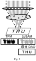
- Fig. 3 is a using principle diagram of digital adaptive optics in one embodiment of the present disclosure.
- TPM two-photon microscopy
- 2pSAM two-photon synthetic aperture microscopy
- the images encode wavefront change characteristics in the small-aperture imaging process while penetrating through the optical aberration and scattering tissues. Therefore, high-quality high-resolution imaging images may be restored through three-dimensional reconstruction by virtue of calculation by using the digital adaptive optics (DAO) method.
- DAO digital adaptive optics
- Fig. 4 is a result map of a fluorescent globule photographed by a multi-photon microscopy applying the digital adaptive optics method in one embodiment of the present disclosure.
- the digital adaptive optics method is applied to an imaging experiment of the fluorescent globule sample.
- the figure on the right shows a normal photographing result of a fluorescent globule having a diameter of 0.2 ⁇ m photographed by an ordinary two-photon microscopy.
- the figure on the left shows an imaging result of the two-photon microscopy after a mismatched correction ring is introduced to increase aberration of the optical system.
- the figure in the middle shows a final imaging result obtained in combination with the two-photon synthetic aperture microscopy for the digital adaptive optics method, and then aberration resistance of the multi-photon microscopy may be exactly increased.
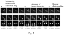
- Fig. 5 is a result map of mouse brain slices photographed by the multi-photon microscopy applying the digital adaptive optics method in one embodiment of the present disclosure.
- the digital adaptive optics method is applied to an imaging experiment of mouse brain slice samples. Through imaging of the mouse brain slice samples of neuron expressed green fluorescent protein and multi-photon imaging under two complicated conditions that a mismatched correction ring is introduced and immersion water is not added under a water immersion objective lens, the effect of increasing aberration resistance of the microscopy in the digital adaptive optics method is measured.
- Fig. 5 is a result map of mouse brain slices photographed by the multi-photon microscopy applying the digital adaptive optics method in one embodiment of the present disclosure.
- the digital adaptive optics method is applied to an imaging experiment of mouse brain slice samples. Through imaging of the mouse brain slice samples of neuron expressed green fluorescent protein and multi-photon imaging under two complicated conditions that a mismatched correction ring is introduced and immersion water is not added under a water immersion objective lens, the effect of increasing aberration resistance of the microscopy in the digital adaptive
- FIG. 7 (B, D, F) are respectively partial enlarged views of Figs. 7 (A, C, E).
- the optical aberration may be compensated according to the lateral shift vectors in the process of obtaining the three-dimensional reconstruction results based on the three-dimensional sample information.
- the compensating optical aberration according to the lateral shift vectors in the process of obtaining three-dimensional reconstruction results based on the three-dimensional sample information includes: applying the wavefront aberration phases determined by the lateral shift vectors to generation of a system point spread function in a preset three-dimensional reconstruction algorithm.
- the wavefront aberration phases may be calculated through a corresponding derivative function relationship of the lateral shift vectors and the wavefront aberration phases according to the lateral shift vectors obtained in the above step so as to regenerate a corrected point spread function during system imaging, wherein the corrected point spread function approximates the most real excitation point spread function in the imaging process.
- the three-dimensional sample information is resolved through the three-dimensional reconstruction algorithm by using the projection of different views obtained by the original measuring data and the phase corrected point spread function, thereby obtaining final sample imaging results.
- Fig. 6 is a process diagram of the two-photon synthetic aperture microscopy for obtaining an aberration phase from shift vectors in one embodiment of the present disclosure.
- the number of sub-apertures used by the two-photon synthetic aperture microscopy is set as 13; a shift map in the axis X and Y direction of a large aperture composed of the sub-apertures may be obtained by virtue of the shift vectors of the image of 13 sub-apertures; and specific distribution and sizes of corresponding large-aperture aberration phases may be calculated through integration by virtue of the shift map.
- the wavefront aberration phases determined by the lateral shift vectors may be applied to generation of the system point spread function in the preset three-dimensional reconstruction algorithm.
- decreased image quality caused by the optical aberration is restored; and the resolution of the final imaging results is increased.
- translation of image information under the objective lens is a derivative function of wavefront deformation of an objective lens aperture plane, i.e., the phase of the wavefront aberration of the incident light may be solved by integrating the lateral shift vectors of the small-aperture imaging results.
- Fig. 7 is a principle diagram of producing lateral shift of sub-aperture images caused by wavefront aberration in one embodiment of the present disclosure.
- the incident light wavefront function is ⁇ 0 (x, y) and becomes ⁇ (x, y) after the optical aberration of the optical system or tissue scattering of the three-dimensional sample; the various small apertures respectively correspond to different lateral shift vectors; and the corresponding derivative function of the lateral shift vectors and the wavefront aberration phases is shown as the formula in the figure.
- the compensating optical aberration according to the lateral shift vectors in the process of obtaining three-dimensional reconstruction results based on the three-dimensional sample information includes: compensating the lateral shift vectors in the preset three-dimensional reconstruction algorithm, and then performing three-dimensional reconstruction.
- lateral shift of the original measuring data may be compensated in the three-dimensional reconstruction algorithm; then a subsequent three-dimensional reconstruction algorithm is continuously implemented on the compensated data; three-dimensional information of the sample is further resolved; and the shift vectors are applied to a three-dimensional reconstruction algorithm for next iteration.
- the lateral shift vectors may be compensated in the preset three-dimensional reconstruction algorithm, and then three-dimensional reconstruction is performed, so that the resolution and quality of the images are increased. Therefore, the multi-photon imaging has higher practicability.
- the optical aberration of the system may be compensated according to digital adaptive optics based on the lateral shift vectors produced by the various small-aperture images, and three-dimensional reconstruction of the sample information may be performed, so that multi-photon imaging of high resolution and high body imaging velocity is realized; robustness and practicability of the optical system are increased; and then imaging efficiency is higher.
- the problems in related technologies that the imaging velocity of the system is decreased since the imaging environment needs to be measured in advance before acquisition of the aberration phase, the wavefront aberration compensation process depends on the active optical device, complexity of the optical system is increased, high-quality multi-photon imaging cannot be quickly realized, imaging efficiency of the optical system is decreased and practicability is lower are solved.
- Fig. 8 is a structural schematic diagram of the digital adaptive optics device for multi-photon imaging provided by the embodiments of the present disclosure.
- the digital adaptive optics device 10 for multi-photon imaging includes: an acquiring module 100, a calculating module 200 and an imaging module 300.
- the acquiring module 100 is configured to acquire three-dimensional sample projection of different views based on the two-photon synthetic aperture microscopy by utilizing small-aperture excitation light beams constrained by a preset diffraction limit size aperture, and generate small-aperture imaging results of different views.
- the calculating module 200 is configured to calculate, based on the small-aperture imaging results, lateral shift vectors produced by images of different sub-apertures caused by wavefront aberration phases brought by system aberration or tissue scattering in the imaging process based on the small-aperture imaging results, and acquire three-dimensional sample information that meets preset resolution conditions.
- the imaging module 300 is configured to compensate optical aberration according to the lateral shift vectors in the process of obtaining three-dimensional reconstruction results based on the three-dimensional sample information.
- the imaging module 300 includes: a correction unit.
- the correction unit is configured to apply the wavefront aberration phases determined by the lateral shift vectors to generation of a system point spread function in the preset three-dimensional reconstruction algorithm.
- the imaging module 300 includes: a compensating unit.
- the compensating unit is configured to compensate the lateral shift vectors in the preset three-dimensional reconstruction algorithm, and then performing three-dimensional reconstruction.
- the optical aberration of the system may be compensated according to digital adaptive optics based on the lateral shift vectors produced by various small-aperture images, and three-dimensional reconstruction of the sample information may be performed, so that multi-photon imaging of high resolution and high body imaging velocity is realized; robustness and practicability of the optical system are increased; and then imaging efficiency is higher.
- the problems in the related technologies that the imaging velocity of the system is decreased since the imaging environment needs to be measured in advance before acquisition of the aberration phase, the wavefront aberration compensation process depends on the active optical device, complexity of the optical system is increased, high-quality multi-photon imaging cannot be quickly realized, imaging efficiency of the optical system is decreased and practicability is lower are solved.
- Fig. 9 is a structural schematic diagram of an electronic device provided by the embodiments of the present disclosure.
- the electronic device may include: a memory 901, a processor 902, and a computer program stored in the memory 901 and executed in the processor 902.
- the processor 902 executes the program to implement the digital adaptive optics method for multi-photon imaging provided in the above embodiments.
- the electronic device includes: a communication interface 903 configured for communication between the memory 901 and the processor 902.
- the memory 901 is configured for storing the computer program that may be executed in the processor 902.
- the memory 901 may include a high-speed RAM memory and may further include a non-volatile memory, such as at least one disk memory.
- the communication interface 903, the memory 901 and the processor 902 may be connected with one another through buses and may complete communication with one another.
- the buses may be an industry standard architecture (ISA) bus, a peripheral component interconnect (PCI) bus or an extended industry standard architecture (EISA) bus, etc.
- ISA industry standard architecture
- PCI peripheral component interconnect
- EISA extended industry standard architecture
- the buses may be divided into an address bus, a data bus, a control bus and the like. For simple representation, the buses are only represented by a thick line in Fig. 9 , but it does not mean that there is only one bus or one kind of bus.
- the memory 901, the processor 902 and the communication interface 903 are integrated on one chip, communication among the memory 901, the processor 902 and the communication interface 903 may be completed through an internal interface.
- the processor 902 may be a central processing unit (CPU), or an application specific integrated circuit (ASIC), or be configured as one or more integrated circuits for implementing the embodiments of the present disclosure.
- CPU central processing unit
- ASIC application specific integrated circuit
- the present embodiment further provides a computer readable storage medium.
- Computer programs are stored in the computer readable storage medium.
- the above regional integrated energy system-oriented carbon emission flow calculation method is realized when the programs are executed by the processor.
- Logics and/or steps represented in the flow chart or described herein in other modes may be specifically implemented in any computer readable medium to be used by instruction execution systems, apparatuses or devices (such as a computer-based system, a system including a processor, or any other system that can fetch instructions from the instruction execution system, apparatus or device and execute the instructions), or to be used in combination with these instruction execution systems, apparatuses or devices.
- the "computer readable medium” may be any apparatus that may include storage, communication, propagation or transmission programs to be used by the instruction execution systems, apparatuses or devices or to be used in combination with these instruction execution systems, apparatuses or devices.
- the computer readable medium include: an electrical connection part (electronic apparatus) having one or N wirings, a portable computer cassette (magnetic apparatus), a random access memory (RAM), a read-only memory (ROM), an erasable programmable read-only memory (EPROM or a flash memory), an optical fiber apparatus and a portable CD read-only memory (CDROM).
- the computer readable medium even may be paper on which the programs may be printed or any other appropriate medium, because the paper or any other medium may be, for example, subjected to optical scanning and then edited and interpreted or the programs are obtained electronically by processing the paper or any other medium in any other appropriate manner when necessary. Then, the programs are stored in the computer memory.
- N steps or methods may be implemented by software or firmware that is stored in the memory and executed by an appropriate instruction execution system.
- the steps or methods may be implemented by any or a combination thereof in the following known technologies in the art: a discrete logic circuit having a logic gate circuit used for realizing logic functions for data signals, an application specific integrated circuit having an appropriate combinational logic gate circuit, a programmable gate array (PGA), a field-programmable gate array (FPGA), etc.
- total or partial steps for realizing the method in the above embodiments may be completed by instructing associated hardware through programs.
- the programs may be stored in a computer readable storage medium.
- the programs include one of the steps in the method embodiments or a combination of the steps during execution.
- each unit may also be of physical existence alone; and two or more units may also be integrated in a module.
- the above integrated module may be implemented in the form of hardware, and may also be implemented in the form of software function module. If implemented in the form of software function module and sold or used serving as an independent product, the integrated module may also be stored in a computer readable storage medium.
- the above mentioned storage medium may be a read-only memory, a magnetic disk or a compact disc.
Landscapes
- Physics & Mathematics (AREA)
- General Physics & Mathematics (AREA)
- Optics & Photonics (AREA)
- Chemical & Material Sciences (AREA)
- Analytical Chemistry (AREA)
- Engineering & Computer Science (AREA)
- Computer Vision & Pattern Recognition (AREA)
- General Engineering & Computer Science (AREA)
- Microscoopes, Condenser (AREA)
Abstract
Description
- The present application is provided based on the
Chinese patent application No. 202310214960.7 on March 07, 2023 - The present disclosure relates to the technical field of microscopy imaging, and particularly relates to a digital adaptive optics method and a device for multi-photon imaging.
- With the continuous development of laser technology, multi-photon microscopy is widely applied to increasing life science researches, has large penetration depth and high chromatographic capacity, and is applicable to imaging of deep scattering samples.
- In related technologies, in presence of optical aberration of optical systems or tissue scattering of three-dimensional samples, image quality of the multi-photon imaging microscopy will be significantly decreased. The system aberration may be compensated through adaptive optics by measuring the aberration of the optical system during imaging.
- However, in the related technologies, problems that imaging velocity of the system is decreased since an imaging environment needs to be measured in advance before acquisition of an aberration phase, the wavefront aberration compensation process depends on an active optical device, complexity of the optical system is increased, high-quality multi-photon imaging cannot be quickly realized, imaging efficiency of the optical system is decreased and practicability is lower urgently need to be solved.
- The present disclosure provides a digital adaptive optics method and a device for multi-photon imaging, for solving problems in related technologies that imaging velocity of the system is decreased since an imaging environment needs to be measured in advance before acquisition of an aberration phase, the wavefront aberration compensation process depends on an active optical device, complexity of the optical system is increased, high-quality multi-photon imaging cannot be quickly realized, imaging efficiency of the optical system is decreased and practicability is lower.
- Embodiments of the first aspect of the present disclosure provide a digital adaptive optics method for multi-photon imaging. The method includes the following steps: acquiring three-dimensional sample projection of different views based on a two-photon synthetic aperture microscopy by utilizing small-aperture excitation light beams constrained by a preset diffraction limit size aperture, and generating small-aperture imaging results of different views; calculating, based on the small-aperture imaging results, lateral shift vectors produced by images of different sub-apertures caused by wavefront aberration phases brought by system aberration or tissue scattering in the imaging process, and acquiring three-dimensional sample information that meets preset resolution conditions; and compensating optical aberration according to the lateral shift vectors in a process of obtaining three-dimensional reconstruction results based on the three-dimensional sample information.
- Further, in one embodiment of the present disclosure, the compensating optical aberration according to the lateral shift vectors in the process of obtaining three-dimensional reconstruction results based on the three-dimensional sample information includes: applying the wavefront aberration phases determined by the lateral shift vectors to generation of a system point spread function in a preset three-dimensional reconstruction algorithm.
- Specifically, in one embodiment of the present disclosure, a derivative function of the lateral shift vectors and the wavefront aberration phases meets the relationship as follows:

wherein Δφ is an aberration phase variation; φ(x, y) is an incident light wavefront function after aberration;

- Further, in one embodiment of the present disclosure, the compensating optical aberration according to the lateral shift vectors in the process of obtaining three-dimensional reconstruction results based on the three-dimensional sample information includes: compensating the lateral shift vectors in the preset three-dimensional reconstruction algorithm, and then performing the three-dimensional reconstruction.
- Embodiments of the second aspect of the present disclosure provide a digital adaptive optics device for multi-photon imaging. The device includes: an acquiring module configured to acquire three-dimensional sample projection of different views based on a two-photon synthetic aperture microscopy by utilizing small-aperture excitation light beams constrained by a preset diffraction limit size aperture, and generate small-aperture imaging results of different views; a calculating module configured to calculate, based on the small-aperture imaging results, lateral shift vectors produced by images of different sub-apertures caused by wavefront aberration phases brought by system aberration or tissue scattering in an imaging process, and acquire three-dimensional sample information that meets preset resolution conditions; and an imaging module configured to compensate optical aberration according to the lateral shift vectors in a process of obtaining three-dimensional reconstruction results based on the three-dimensional sample information.
- Further, in one embodiment of the present disclosure, the imaging module includes: a correction unit configured to apply the wavefront aberration phases determined by the lateral shift vectors to generation of a system point spread function in a preset three-dimensional reconstruction algorithm.
- Specifically, in one embodiment of the present disclosure, a derivative function of the lateral shift vectors and the wavefront aberration phases meets the relationship as follows:

wherein Δφ is an aberration phase variation; φ(x, y) is an incident light wavefront function after aberration;

- Further, in one embodiment of the present disclosure, the imaging module includes: a compensating unit configured to compensate the lateral shift vectors in the preset three-dimensional reconstruction algorithm, and then perform the three-dimensional reconstruction.
- Embodiments of the third aspect of the present disclosure provide an electronic device. The electronic device includes a memory, a processor, and a computer program stored in the memory and executed in the processor. The processor executes the program to implement the digital adaptive optics method for multi-photon imaging in the above embodiments.
- Embodiments of the fourth aspect of the present disclosure provide a computer readable storage medium. A computer program is stored in the computer readable storage medium. The program is executed by a processor to implement the above digital adaptive optics method for multi-photon imaging.
- In the embodiments of the present disclosure, the optical aberration of the system may be compensated according to digital adaptive optics based on the lateral shift vectors produced by various small-aperture images, and three-dimensional reconstruction of the sample information may be performed, so that multi-photon imaging of high resolution and high body imaging velocity is realized; robustness and practicability of the optical system are increased; and then imaging efficiency is higher. Therefore, the problems in related technologies that the imaging velocity of the system is decreased since the imaging environment needs to be measured in advance before acquisition of the aberration phase, the wavefront aberration compensation process depends on the active optical device, complexity of the optical system is increased, high-quality multi-photon imaging cannot be quickly realized, imaging efficiency of the optical system is decreased and practicability is lower are solved.
- Additional aspects and advantages of the present disclosure will be partially described below, some of which will be obvious in descriptions below or be understood through practice of the present disclosure.
- The above and/or additional aspects and advantages of the present disclosure will be obvious and easily understood in descriptions of the embodiments in combination with drawings below, wherein:
-
Fig. 1 is a flow chart of a digital adaptive optics method for multi-photon imaging provided by embodiments of the present disclosure; -
Fig. 2 is a process diagram of image shift vectors caused by aberration calculated through digital adaptive optics in one embodiment of the present disclosure; -
Fig. 3 is a using principle diagram of digital adaptive optics in one embodiment of the present disclosure; -
Fig. 4 is a result map of a fluorescent globule photographed by a multi-photon microscopy applying a digital adaptive optics method in one embodiment of the present disclosure; -
Fig. 5 is a result map of mouse brain slices photographed by a multi-photon microscopy applying a digital adaptive optics method in one embodiment of the present disclosure; -
Fig. 6 is a process diagram of a two-photon synthetic aperture microscopy for obtaining an aberration phase from shift vectors in one embodiment of the present disclosure; -
Fig. 7 is a principle diagram of producing lateral shift of sub-aperture images caused by wavefront aberration in one embodiment of the present disclosure; -
Fig. 8 is a structural schematic diagram of a digital adaptive optics device for multi-photon imaging provided by embodiments of the present disclosure; and -
Fig. 9 is a structural schematic diagram of an electronic device provided by embodiments of the present disclosure. - Embodiments of the present disclosure will be described in detail below. Examples of the embodiments are illustrated in the drawings, wherein identical or similar symbols refer to identical or similar components or components having identical or similar functions throughout. Embodiments described through reference drawings below are illustrative and are intended to be used for explaining the present disclosure rather than limiting the present disclosure.
- A digital adaptive optics method and a device for multi-photon imaging provided by the embodiments of the present disclosure are described below with reference to drawings. With respect to problems in related technologies mentioned in the background that imaging velocity of the system is decreased since an imaging environment needs to be measured in advance before acquisition of an aberration phase, the wavefront aberration compensation process depends on an active optical device, complexity of the optical system is increased, high-quality multi-photon imaging cannot be quickly realized, imaging efficiency of the optical system is decreased and practicability is lower, the present disclosure provides a digital adaptive optics method for multi-photon imaging. The optical aberration of the system may be compensated according to digital adaptive optics based on the lateral shift vectors produced by various small-aperture images, and three-dimensional reconstruction of the sample information may be performed, so that multi-photon imaging of high resolution and high body imaging velocity is realized; robustness and practicability of the optical system are increased; and then imaging efficiency is higher. Therefore, the problems in the related technologies that the imaging velocity of the system is decreased since the imaging environment needs to be measured in advance before acquisition of the aberration phase, the wavefront aberration compensation process depends on the active optical device, complexity of the optical system is increased, high-quality multi-photon imaging cannot be quickly realized, imaging efficiency of the optical system is decreased and practicability is lower are solved.
- Specifically,
Fig. 1 is a flow diagram of the digital adaptive optics method for multi-photon imaging provided by embodiments of the present disclosure. - As shown in
Fig. 1 , the digital adaptive optics method for multi-photon imaging includes the following steps:
In step S101, three-dimensional sample projection of different views is acquired based on a two-photon synthetic aperture microscopy by utilizing small-aperture excitation light beams constrained by a preset diffraction limit size aperture, and small-aperture imaging results of different views are generated. - It can be understood that, in the embodiments of the present disclosure, sample imaging may be realized by the two-photon synthetic aperture microscopy in a process of synthesizing large apertures from sub-apertures; the three-dimensional sample projection of different views may be acquired by excitation light beams by using multiple small apertures; an image generated by each small aperture is obtained by a point spread function during system imaging; and then small-aperture imaging results of different views are obtained.
- It should be noted that, the preset diffraction limit size is set by those skilled in the art according to actual situations, and is not specifically defined herein.
- In the embodiments of the present disclosure, the three-dimensional sample projection of different views may be acquired based on the two-photon synthetic aperture microscopy by utilizing the small-aperture excitation light beams constrained by the preset diffraction limit size aperture, and the small-aperture imaging results of different views are generated. Therefore, related imaging information is provided for further application of the digital adaptive optics in the following steps; and data basis needed by aberration correction in the multi-photon imaging process is met.
- In step S102, lateral shift vectors produced by images of different sub-apertures caused by wavefront aberration phases brought by system aberration or tissue scattering in the imaging process are calculated based on the small-aperture imaging results, and three-dimensional sample information that meets preset resolution conditions is acquired.
- It can be understood that, in the embodiments of the present disclosure, wavefront deformation of incident excitation light may be caused by the optical system aberration or tissue scattering, while the wavefront deformation of the incident light may cause lateral shift of images photographed with small-aperture at different positions. The lateral shift may be processed with respect to the obtained small-aperture imaging results of different views in the above steps by virtue of a three-dimensional reconstruction algorithm arranged in the two-photon synthetic aperture microscopy, thereby acquiring the three-dimensional sample information that meets preset resolution conditions.
- It should be noted that, the preset resolution conditions are set by those skilled in the art according to actual situations, and are not specifically defined herein.
- Specifically, the process of acquiring the lateral shift vectors produced by the images of different sub-apertures is shown as
Fig. 2 . As shown inFig. 2(A) , the obtained three-dimensional data and the imaging point spread function may be subjected to convolution operation through the three-dimensional reconstruction algorithm to obtain forward projection P(x, y) of an original measuring view; the forward projection and original measuring data M(x, y) are subjected to correlation calculation to obtain a correlation matrix; a maximum value of the correlation matrix is the coordinate of a maximum correlation position; a distance of coordinates deviating from the central position is (Shift x, Shift y); and shift vectors

Fig. 2(B) , when the number of the small apertures is 13, shift distance calculation results of three views and corresponding position and correlation curves are as shown in the figure. - In the embodiments of the present disclosure, the lateral shift vectors produced by the images of different sub-apertures caused by wavefront aberration phases brought by system aberration or tissue scattering in the imaging process may be calculated based on the small-aperture imaging results, and three-dimensional sample information that meets the preset resolution conditions is acquired. Therefore, data processing of the digital adaptive optics method applied to the two-photon synthetic aperture microscopy is realized; and executability of aberration correction of multi-photon imaging is increased.
- In step S103, optical aberration is compensated according to the lateral shift vectors in a process of obtaining three-dimensional reconstruction results based on the three-dimensional sample information.
- It can be understood that, in the embodiments of the present disclosure, photographing time during imaging does not need to be occupied in a specific implementation process of compensating the optical aberration according to the lateral shift vectors; and aberration compensation is performed during later imaging data processing, thereby further obtaining three-dimensional reconstruction results based on the three-dimensional sample information and obtaining final imaging images.
- For example,
Fig. 3 is a using principle diagram of digital adaptive optics in one embodiment of the present disclosure. When a traditional two-photon microscopy (TPM) encounters optical aberration or sample scattering, imaging quality is decreased. However, when small-aperture imaging results of different views are detected by the two-photon synthetic aperture microscopy (2pSAM), the images encode wavefront change characteristics in the small-aperture imaging process while penetrating through the optical aberration and scattering tissues. Therefore, high-quality high-resolution imaging images may be restored through three-dimensional reconstruction by virtue of calculation by using the digital adaptive optics (DAO) method. -
Fig. 4 is a result map of a fluorescent globule photographed by a multi-photon microscopy applying the digital adaptive optics method in one embodiment of the present disclosure. The digital adaptive optics method is applied to an imaging experiment of the fluorescent globule sample. The figure on the right shows a normal photographing result of a fluorescent globule having a diameter of 0.2 µm photographed by an ordinary two-photon microscopy. The figure on the left shows an imaging result of the two-photon microscopy after a mismatched correction ring is introduced to increase aberration of the optical system. The figure in the middle shows a final imaging result obtained in combination with the two-photon synthetic aperture microscopy for the digital adaptive optics method, and then aberration resistance of the multi-photon microscopy may be exactly increased. -
Fig. 5 is a result map of mouse brain slices photographed by the multi-photon microscopy applying the digital adaptive optics method in one embodiment of the present disclosure. The digital adaptive optics method is applied to an imaging experiment of mouse brain slice samples. Through imaging of the mouse brain slice samples of neuron expressed green fluorescent protein and multi-photon imaging under two complicated conditions that a mismatched correction ring is introduced and immersion water is not added under a water immersion objective lens, the effect of increasing aberration resistance of the microscopy in the digital adaptive optics method is measured. InFig. 5 , ordinary two-photon microscopy imaging results (TPM, w/o deconv), deconvolution of full-aperture point spread function performed on the ordinary two-photon microscopy imaging results (TPM, w/ deconv), and imaging results of the two-photon synthetic aperture microscopy without using the digital adaptive optics method (2pSAM, w/o DAO) and imaging results of the two-photon synthetic aperture microscopy using the digital adaptive optics method (2pSAM, w/ DAO) are compared. Fig. 7(E) shows an image result of the two-photon microscopy under normal photographing conditions, and the image result serving as a truth value for providing control.Figs. 7 (B, D, F) are respectively partial enlarged views ofFigs. 7 (A, C, E). Thus, it can be seen that, image quality of the two-photon synthetic aperture microscopy in combination with the digital adaptive optics method is increased and restored; and the resolution is restored. - In the embodiments of the present disclosure, the optical aberration may be compensated according to the lateral shift vectors in the process of obtaining the three-dimensional reconstruction results based on the three-dimensional sample information. By applying the digital adaptive optics method to the two-photon synthetic aperture microscopy, the imaging velocity and imaging quality of the optical system are increased. Therefore, high-resolution multi-photon imaging results are obtained; and practicability is high.
- Further, in one embodiment of the present disclosure, the compensating optical aberration according to the lateral shift vectors in the process of obtaining three-dimensional reconstruction results based on the three-dimensional sample information includes: applying the wavefront aberration phases determined by the lateral shift vectors to generation of a system point spread function in a preset three-dimensional reconstruction algorithm.
- It can be understood that, in the embodiments of the present disclosure, the wavefront aberration phases may be calculated through a corresponding derivative function relationship of the lateral shift vectors and the wavefront aberration phases according to the lateral shift vectors obtained in the above step so as to regenerate a corrected point spread function during system imaging, wherein the corrected point spread function approximates the most real excitation point spread function in the imaging process. Further, the three-dimensional sample information is resolved through the three-dimensional reconstruction algorithm by using the projection of different views obtained by the original measuring data and the phase corrected point spread function, thereby obtaining final sample imaging results.
- It should be noted that, the preset three-dimensional reconstruction algorithm is set by those skilled in the art according to actual situations, and is not specifically defined herein.
-
Fig. 6 is a process diagram of the two-photon synthetic aperture microscopy for obtaining an aberration phase from shift vectors in one embodiment of the present disclosure. The number of sub-apertures used by the two-photon synthetic aperture microscopy is set as 13; a shift map in the axis X and Y direction of a large aperture composed of the sub-apertures may be obtained by virtue of the shift vectors of the image of 13 sub-apertures; and specific distribution and sizes of corresponding large-aperture aberration phases may be calculated through integration by virtue of the shift map. - In the embodiments of the present disclosure, the wavefront aberration phases determined by the lateral shift vectors may be applied to generation of the system point spread function in the preset three-dimensional reconstruction algorithm. Thus, decreased image quality caused by the optical aberration is restored; and the resolution of the final imaging results is increased.
- Specifically, in one embodiment of the present disclosure, a derivative function of the lateral shift vectors and the wavefront aberration phases meets the relationship as follows:

wherein Δφ is an aberration phase variation; φ(x, y) is an incident light wavefront function after aberration;

- It can be understood that, according to the wave optics theory, translation of image information under the objective lens is a derivative function of wavefront deformation of an objective lens aperture plane, i.e., the phase of the wavefront aberration of the incident light may be solved by integrating the lateral shift vectors of the small-aperture imaging results.
-
Fig. 7 is a principle diagram of producing lateral shift of sub-aperture images caused by wavefront aberration in one embodiment of the present disclosure. The incident light wavefront function is φ 0(x, y) and becomes φ(x, y) after the optical aberration of the optical system or tissue scattering of the three-dimensional sample; the various small apertures respectively correspond to different lateral shift vectors; and the corresponding derivative function of the lateral shift vectors and the wavefront aberration phases is shown as the formula in the figure. - Further, in one embodiment of the present disclosure, the compensating optical aberration according to the lateral shift vectors in the process of obtaining three-dimensional reconstruction results based on the three-dimensional sample information includes: compensating the lateral shift vectors in the preset three-dimensional reconstruction algorithm, and then performing three-dimensional reconstruction.
- It can be understood that, in the embodiments of the present disclosure, according to the image shift vectors


- In the embodiments of the present disclosure, the lateral shift vectors may be compensated in the preset three-dimensional reconstruction algorithm, and then three-dimensional reconstruction is performed, so that the resolution and quality of the images are increased. Therefore, the multi-photon imaging has higher practicability.
- According to the digital adaptive optics method for multi-photon imaging provided by the embodiments of the present disclosure, the optical aberration of the system may be compensated according to digital adaptive optics based on the lateral shift vectors produced by the various small-aperture images, and three-dimensional reconstruction of the sample information may be performed, so that multi-photon imaging of high resolution and high body imaging velocity is realized; robustness and practicability of the optical system are increased; and then imaging efficiency is higher. Therefore, the problems in related technologies that the imaging velocity of the system is decreased since the imaging environment needs to be measured in advance before acquisition of the aberration phase, the wavefront aberration compensation process depends on the active optical device, complexity of the optical system is increased, high-quality multi-photon imaging cannot be quickly realized, imaging efficiency of the optical system is decreased and practicability is lower are solved.
- Further, the digital adaptive optics device for multi-photon imaging provided by the embodiments of the present disclosure is described with reference to drawings.
-
Fig. 8 is a structural schematic diagram of the digital adaptive optics device for multi-photon imaging provided by the embodiments of the present disclosure. - As shown in
Fig. 8 , the digitaladaptive optics device 10 for multi-photon imaging includes: an acquiringmodule 100, a calculatingmodule 200 and animaging module 300. - The acquiring
module 100 is configured to acquire three-dimensional sample projection of different views based on the two-photon synthetic aperture microscopy by utilizing small-aperture excitation light beams constrained by a preset diffraction limit size aperture, and generate small-aperture imaging results of different views. - The calculating
module 200 is configured to calculate, based on the small-aperture imaging results, lateral shift vectors produced by images of different sub-apertures caused by wavefront aberration phases brought by system aberration or tissue scattering in the imaging process based on the small-aperture imaging results, and acquire three-dimensional sample information that meets preset resolution conditions. - The
imaging module 300 is configured to compensate optical aberration according to the lateral shift vectors in the process of obtaining three-dimensional reconstruction results based on the three-dimensional sample information. - Further, in one embodiment of the present disclosure, the
imaging module 300 includes: a correction unit. - The correction unit is configured to apply the wavefront aberration phases determined by the lateral shift vectors to generation of a system point spread function in the preset three-dimensional reconstruction algorithm.
- Specifically, in one embodiment of the present disclosure, a derivative function of the lateral shift vectors and the wavefront aberration phases meets the relationship as follows:

wherein Δφ is an aberration phase variation; φ(x, y) is an incident light wavefront function after aberration;

- Further, in one embodiment of the present disclosure, the
imaging module 300 includes: a compensating unit. - The compensating unit is configured to compensate the lateral shift vectors in the preset three-dimensional reconstruction algorithm, and then performing three-dimensional reconstruction.
- It should be noted that, the explanation of the above digital adaptive optics method for multi-photon imaging is also applicable to the digital adaptive optics device for multi-photon imaging in the present embodiment. Unnecessary details are not given herein.
- According to the digital adaptive optics device for multi-photon imaging provided by the embodiments of the present disclosure, the optical aberration of the system may be compensated according to digital adaptive optics based on the lateral shift vectors produced by various small-aperture images, and three-dimensional reconstruction of the sample information may be performed, so that multi-photon imaging of high resolution and high body imaging velocity is realized; robustness and practicability of the optical system are increased; and then imaging efficiency is higher. Therefore, the problems in the related technologies that the imaging velocity of the system is decreased since the imaging environment needs to be measured in advance before acquisition of the aberration phase, the wavefront aberration compensation process depends on the active optical device, complexity of the optical system is increased, high-quality multi-photon imaging cannot be quickly realized, imaging efficiency of the optical system is decreased and practicability is lower are solved.
-
Fig. 9 is a structural schematic diagram of an electronic device provided by the embodiments of the present disclosure. The electronic device may include:
amemory 901, aprocessor 902, and a computer program stored in thememory 901 and executed in theprocessor 902. - The
processor 902 executes the program to implement the digital adaptive optics method for multi-photon imaging provided in the above embodiments. - Further, the electronic device includes:
acommunication interface 903 configured for communication between thememory 901 and theprocessor 902. - The
memory 901 is configured for storing the computer program that may be executed in theprocessor 902. - The
memory 901 may include a high-speed RAM memory and may further include a non-volatile memory, such as at least one disk memory. - If the
memory 901, theprocessor 902 and thecommunication interface 903 are implemented independently, thecommunication interface 903, thememory 901 and theprocessor 902 may be connected with one another through buses and may complete communication with one another. The buses may be an industry standard architecture (ISA) bus, a peripheral component interconnect (PCI) bus or an extended industry standard architecture (EISA) bus, etc. The buses may be divided into an address bus, a data bus, a control bus and the like. For simple representation, the buses are only represented by a thick line inFig. 9 , but it does not mean that there is only one bus or one kind of bus. - Optionally, in specific implementation, if the
memory 901, theprocessor 902 and thecommunication interface 903 are integrated on one chip, communication among thememory 901, theprocessor 902 and thecommunication interface 903 may be completed through an internal interface. - The
processor 902 may be a central processing unit (CPU), or an application specific integrated circuit (ASIC), or be configured as one or more integrated circuits for implementing the embodiments of the present disclosure. - The present embodiment further provides a computer readable storage medium. Computer programs are stored in the computer readable storage medium. The above regional integrated energy system-oriented carbon emission flow calculation method is realized when the programs are executed by the processor.
- In the illustration of this description, the illustration of reference terms "one embodiment", "some embodiments", "example", "specific example" or "some examples", etc. means that specific features, structures, materials or characteristics illustrated in combination with the embodiment or example are included in at least one embodiment or example of the present disclosure. In this description, exemplary statements for the above terms do not must aim at the same embodiment or example. Moreover, the described specific features, structures, materials or characteristics can be combined appropriately in any one or N embodiments or examples. In addition, without conflict, those skilled in the art can combine and integrate different embodiments or examples illustrated in this description and the features of different embodiments or examples.
- In addition, the terms such as "first" and "second" are only used for the purpose of description, rather than being understood to indicate or imply relative importance or hint the number of indicated technical features. Thus, the features limited by "first" and "second" can explicitly or impliedly comprise at least one of the features. In the description of the present disclosure, the meaning of "N" is at least two, such as two, three, etc. unless otherwise clearly specified.
- The flow chart or any procedure or method description described in any other manner herein may be understood to represent a module, a fragment or a part including one or more N codes of executable instructions in steps used for realizing customized logic functions or procedures. Moreover, the scope of preferred implementation modes of the present disclosure includes additional implementations, wherein the functions may be executed out of the illustrated or discussed sequence, including a basically simultaneous manner according to the involved functions or in reverse order, which should be understood by those skilled in the art in the embodiments of the present disclosure.
- Logics and/or steps represented in the flow chart or described herein in other modes, i.e., a definite sequence table of executable instructions that may be considered to be used for realizing logic functions, may be specifically implemented in any computer readable medium to be used by instruction execution systems, apparatuses or devices (such as a computer-based system, a system including a processor, or any other system that can fetch instructions from the instruction execution system, apparatus or device and execute the instructions), or to be used in combination with these instruction execution systems, apparatuses or devices. For the present description, the "computer readable medium" may be any apparatus that may include storage, communication, propagation or transmission programs to be used by the instruction execution systems, apparatuses or devices or to be used in combination with these instruction execution systems, apparatuses or devices. More specific examples (a non-exhaustive list) of the computer readable medium include: an electrical connection part (electronic apparatus) having one or N wirings, a portable computer cassette (magnetic apparatus), a random access memory (RAM), a read-only memory (ROM), an erasable programmable read-only memory (EPROM or a flash memory), an optical fiber apparatus and a portable CD read-only memory (CDROM). In addition, the computer readable medium even may be paper on which the programs may be printed or any other appropriate medium, because the paper or any other medium may be, for example, subjected to optical scanning and then edited and interpreted or the programs are obtained electronically by processing the paper or any other medium in any other appropriate manner when necessary. Then, the programs are stored in the computer memory.
- It should be understood that, various parts of the present disclosure may be implemented by hardware, software, firmware or combinations thereof. In the above implementation modes, N steps or methods may be implemented by software or firmware that is stored in the memory and executed by an appropriate instruction execution system. For example, if the implementation by hardware is the same as that in another implementation mode, the steps or methods may be implemented by any or a combination thereof in the following known technologies in the art: a discrete logic circuit having a logic gate circuit used for realizing logic functions for data signals, an application specific integrated circuit having an appropriate combinational logic gate circuit, a programmable gate array (PGA), a field-programmable gate array (FPGA), etc.
- Those ordinary skilled in the art may understand that, total or partial steps for realizing the method in the above embodiments may be completed by instructing associated hardware through programs. The programs may be stored in a computer readable storage medium. The programs include one of the steps in the method embodiments or a combination of the steps during execution.
- In addition, various functional units in each embodiment of the present disclosure may be integrated in a processing module; each unit may also be of physical existence alone; and two or more units may also be integrated in a module. The above integrated module may be implemented in the form of hardware, and may also be implemented in the form of software function module. If implemented in the form of software function module and sold or used serving as an independent product, the integrated module may also be stored in a computer readable storage medium.
- The above mentioned storage medium may be a read-only memory, a magnetic disk or a compact disc. Although the embodiments of the present disclosure have been illustrated and described above, it should be understood that, the above embodiments are illustrative and cannot be understood as a limitation to the present disclosure. Changes, modifications, replacements and transformations of the above embodiments may be made by those ordinary skilled in the art in the scope of the present disclosure.
Claims (10)
- A digital adaptive optics method for multi-photon imaging, comprising:acquiring three-dimensional sample projection of different views based on a two-photon synthetic aperture microscopy by utilizing small-aperture excitation light beams constrained by a preset diffraction limit size aperture, and generating small-aperture imaging results of different views;calculating, based on the small-aperture imaging results, lateral shift vectors produced by images of different sub-apertures caused by wavefront aberration phases brought by system aberration or tissue scattering in an imaging process, and acquiring three-dimensional sample information that meets preset resolution conditions; andcompensating optical aberration according to the lateral shift vectors in a process of obtaining three-dimensional reconstruction results based on the three-dimensional sample information.
- The method according to claim 1, wherein the compensating optical aberration according to the lateral shift vectors in the process of obtaining three-dimensional reconstruction results based on the three-dimensional sample information comprises:
applying the wavefront aberration phases determined by the lateral shift vectors to generation of a system point spread function in a preset three-dimensional reconstruction algorithm. - The method according to claim 2, wherein a derivative function of the lateral shift vectors and the wavefront aberration phases meets the relationship as follows:


- The method according to claim 1, wherein the compensating optical aberration according to the lateral shift vectors in the process of obtaining three-dimensional reconstruction results based on the three-dimensional sample information comprises:
compensating the lateral shift vectors in the preset three-dimensional reconstruction algorithm, and then performing the three-dimensional reconstruction. - A digital adaptive optics device for multi-photon imaging, comprising:an acquiring module configured to acquire three-dimensional sample projection of different views based on a two-photon synthetic aperture microscopy by utilizing small-aperture excitation light beams constrained by a preset diffraction limit size aperture, and generate small-aperture imaging results of different views;a calculating module configured to calculate, based on the small-aperture imaging results, lateral shift vectors produced by images of different sub-apertures caused by wavefront aberration phases brought by system aberration or tissue scattering in an imaging process, and acquire three-dimensional sample information that meets preset resolution conditions; andan imaging module configured to compensate optical aberration according to the lateral shift vectors in a process of obtaining three-dimensional reconstruction results based on the three-dimensional sample information.
- The device according to claim 5, wherein the imaging module comprises:
a correction unit configured to apply the wavefront aberration phases determined by the lateral shift vectors to generation of a system point spread function in a preset three-dimensional reconstruction algorithm. - The device according to claim 6, wherein a derivative function of the lateral shift vectors and the wavefront aberration phases meets the relationship as follows:


- The device according to claim 5, wherein the imaging module comprises:
a compensating unit configured to compensate the lateral shift vectors in the preset three-dimensional reconstruction algorithm, and then performing the three-dimensional reconstruction. - An electronic device, comprising: a memory, a processor, and a computer program stored in the memory and executed in the processor, wherein the processor executes the program to implement the digital adaptive optics method for multi-photon imaging according to any one of claims 1-4.
- A computer readable storage medium, storing a computer program, wherein the program is executed by a processor to implement the digital adaptive optics method for multi-photon imaging according to any one of claims 1-4.
Applications Claiming Priority (2)
| Application Number | Priority Date | Filing Date | Title |
|---|---|---|---|
| CN202310214960.7A CN116338945B (en) | 2023-03-07 | 2023-03-07 | Digital adaptive optics method and apparatus for multiphoton imaging |
| PCT/CN2023/105687 WO2024183197A1 (en) | 2023-03-07 | 2023-07-04 | Digital adaptive optical method and apparatus for multiphoton microscopy |
Publications (2)
| Publication Number | Publication Date |
|---|---|
| EP4455642A1 true EP4455642A1 (en) | 2024-10-30 |
| EP4455642A4 EP4455642A4 (en) | 2025-01-22 |
Family
ID=86878249
Family Applications (1)
| Application Number | Title | Priority Date | Filing Date |
|---|---|---|---|
| EP23853726.0A Pending EP4455642A4 (en) | 2023-03-07 | 2023-07-04 | Digital adaptive optical method and apparatus for multiphoton microscopy |
Country Status (3)
| Country | Link |
|---|---|
| EP (1) | EP4455642A4 (en) |
| CN (1) | CN116338945B (en) |
| WO (1) | WO2024183197A1 (en) |
Families Citing this family (1)
| Publication number | Priority date | Publication date | Assignee | Title |
|---|---|---|---|---|
| CN116338945B (en) * | 2023-03-07 | 2025-11-04 | 清华大学 | Digital adaptive optics method and apparatus for multiphoton imaging |
Family Cites Families (13)
| Publication number | Priority date | Publication date | Assignee | Title |
|---|---|---|---|---|
| CN100399110C (en) * | 2006-03-30 | 2008-07-02 | 彭斌 | Method for adjusting and firming components built in free space isolator |
| JP6195830B2 (en) * | 2011-07-14 | 2017-09-13 | ホワルド フグヘス メドイクアル インストイトウテ | Microscopy with adaptive optics |
| DE102014102215A1 (en) * | 2014-02-20 | 2015-08-20 | Carl Zeiss Microscopy Gmbh | Method and arrangement for light-sheet microscopy |
| WO2016187675A1 (en) * | 2015-05-28 | 2016-12-01 | Cylite Pty Ltd | High resolution 3-d spectral domain optical imaging apparatus and method |
| CN105832358B (en) * | 2016-03-16 | 2019-02-19 | 西安电子科技大学 | An imaging method based on system calibration of rotating dual-plate PET system |
| WO2019010507A1 (en) * | 2017-07-14 | 2019-01-17 | Wavesense Engineering Gmbh | Optical apparatus |
| DE102017121291A1 (en) * | 2017-09-14 | 2019-03-14 | Carl Zeiss Microscopy Gmbh | Determination of aberrations by means of angle-variable illumination |
| DE102019118446A1 (en) * | 2019-07-08 | 2021-01-14 | Laser-Laboratorium Göttingen e.V. | Method and microscope with a correction device for correcting aberration-induced aberrations |
| CN110954523B (en) * | 2019-12-18 | 2022-07-08 | 深圳大学 | Two-photon scanning structure light microscopic imaging method and device |
| CN113075177B (en) * | 2021-03-18 | 2022-02-11 | 北京大学 | Gallium nitride dislocation two-photon super-resolution microscopic three-dimensional imaging device and method |
| CN113466190B (en) * | 2021-06-02 | 2023-04-07 | 中国科学院西安光学精密机械研究所 | Multi-mode multi-photon laser scanning three-dimensional microscopic imaging device and method |
| CN115512018B (en) * | 2021-06-07 | 2026-01-20 | 广州视源电子科技股份有限公司 | Multi-camera structured light three-dimensional imaging method, device, electronic equipment and storage medium |
| CN116338945B (en) * | 2023-03-07 | 2025-11-04 | 清华大学 | Digital adaptive optics method and apparatus for multiphoton imaging |
-
2023
- 2023-03-07 CN CN202310214960.7A patent/CN116338945B/en active Active
- 2023-07-04 EP EP23853726.0A patent/EP4455642A4/en active Pending
- 2023-07-04 WO PCT/CN2023/105687 patent/WO2024183197A1/en not_active Ceased
Also Published As
| Publication number | Publication date |
|---|---|
| CN116338945A (en) | 2023-06-27 |
| EP4455642A4 (en) | 2025-01-22 |
| WO2024183197A1 (en) | 2024-09-12 |
| CN116338945B (en) | 2025-11-04 |
Similar Documents
| Publication | Publication Date | Title |
|---|---|---|
| CN115546570B (en) | A vascular image segmentation method and system based on three-dimensional deep network | |
| CN117237261A (en) | Image processing method and image processing system | |
| US10330913B2 (en) | Method and device for imaging an object | |
| EP3945307B1 (en) | Three-dimensional optical tomography method and apparatus using partially coherent light and multi-illumination pattern | |
| JP6312419B2 (en) | Digital holography three-dimensional imaging apparatus and imaging method | |
| CN116912103B (en) | Digital aberration correction method and device for meta-imaging optical imaging | |
| CN113409326A (en) | Image segmentation method and system | |
| CN113433130A (en) | Method and device for generating confocal imaging by wide-field imaging | |
| CN114241072B (en) | Laminated imaging reconstruction method and system | |
| EP3554338B1 (en) | Determining eye surface contour using multifocal keratometry | |
| US20170013248A1 (en) | Image generating apparatus, image generating method, and image generating program | |
| CN111077085B (en) | Wavefront-free detector self-adaptive point scanning imaging method based on deep learning | |
| CN102109329A (en) | Thickness-information acquisition apparatus, method, program and microscope | |
| CN119399227B (en) | Spine endoscope image surgical instrument segmentation method and system | |
| EP4451223A1 (en) | Frequency domain phase retrieval method and device for two-photon synthetic aperture microscope | |
| CN116338945B (en) | Digital adaptive optics method and apparatus for multiphoton imaging | |
| CN118097022B (en) | Method and device for stacked imaging under a series of illumination conditions | |
| EP4455640B1 (en) | Two-photon synthetic aperture imaging method and apparatus based on diffraction-limit-sized small aperture | |
| EP4455641A1 (en) | Synthetic aperture-based two-photon microscopic imaging method and apparatus | |
| EP4179497B1 (en) | System and method using convolutional neural networks for microscopy images | |
| CN115337041B (en) | Ultrasonic Doppler imaging method, device and related equipment | |
| KR102778548B1 (en) | Imaging apparatus and method of correcting and reconstructing target image in scattering medium using multiple scattering tracing algorithm based on reflection matrix | |
| US20220392031A1 (en) | Image processing method, image processing apparatus and image processing system | |
| CN115619684B (en) | Microscopic scattering imaging method based on coded camera shooting and non-invasive laser scanning | |
| CN121883278B (en) | A method and apparatus for synthesizing total focusing digital slices based on physical optics models |
Legal Events
| Date | Code | Title | Description |
|---|---|---|---|
| STAA | Information on the status of an ep patent application or granted ep patent |
Free format text: STATUS: UNKNOWN |
|
| STAA | Information on the status of an ep patent application or granted ep patent |
Free format text: STATUS: THE INTERNATIONAL PUBLICATION HAS BEEN MADE |
|
| PUAI | Public reference made under article 153(3) epc to a published international application that has entered the european phase |
Free format text: ORIGINAL CODE: 0009012 |
|
| STAA | Information on the status of an ep patent application or granted ep patent |
Free format text: STATUS: REQUEST FOR EXAMINATION WAS MADE |
|
| 17P | Request for examination filed |
Effective date: 20240223 |
|
| AK | Designated contracting states |
Kind code of ref document: A1 Designated state(s): AL AT BE BG CH CY CZ DE DK EE ES FI FR GB GR HR HU IE IS IT LI LT LU LV MC ME MK MT NL NO PL PT RO RS SE SI SK SM TR |
|
| A4 | Supplementary search report drawn up and despatched |
Effective date: 20250102 |
|
| RIC1 | Information provided on ipc code assigned before grant |
Ipc: G02B 21/00 20060101ALI20241218BHEP Ipc: G01J 3/44 20060101ALI20241218BHEP Ipc: G01N 21/64 20060101AFI20241218BHEP |
|
| STAA | Information on the status of an ep patent application or granted ep patent |
Free format text: STATUS: EXAMINATION IS IN PROGRESS |
|
| 17Q | First examination report despatched |
Effective date: 20250811 |
|
| GRAP | Despatch of communication of intention to grant a patent |
Free format text: ORIGINAL CODE: EPIDOSNIGR1 |
|
| STAA | Information on the status of an ep patent application or granted ep patent |
Free format text: STATUS: GRANT OF PATENT IS INTENDED |
|
| DAV | Request for validation of the european patent (deleted) | ||
| DAX | Request for extension of the european patent (deleted) | ||
| INTG | Intention to grant announced |
Effective date: 20260127 |