EP4455631A1 - Method for forming snow surface for tire evaluation - Google Patents
Method for forming snow surface for tire evaluation Download PDFInfo
- Publication number
- EP4455631A1 EP4455631A1 EP24169313.4A EP24169313A EP4455631A1 EP 4455631 A1 EP4455631 A1 EP 4455631A1 EP 24169313 A EP24169313 A EP 24169313A EP 4455631 A1 EP4455631 A1 EP 4455631A1
- Authority
- EP
- European Patent Office
- Prior art keywords
- snow
- cutting blade
- compressed
- tire
- layer
- Prior art date
- Legal status (The legal status is an assumption and is not a legal conclusion. Google has not performed a legal analysis and makes no representation as to the accuracy of the status listed.)
- Withdrawn
Links
Images



Classifications
-
- G—PHYSICS
- G01—MEASURING; TESTING
- G01M—TESTING STATIC OR DYNAMIC BALANCE OF MACHINES OR STRUCTURES; TESTING OF STRUCTURES OR APPARATUS, NOT OTHERWISE PROVIDED FOR
- G01M17/00—Testing of vehicles
- G01M17/007—Wheeled or endless-tracked vehicles
- G01M17/02—Tyres
- G01M17/022—Tyres the tyre co-operating with rotatable rolls
Definitions
- the present invention relates to a method for forming a snow surface for tire evaluation.
- an artificial snow surface may be provided indoors to evaluate tire performance on the artificial snow surface.
- Japanese Laid-Open Patent Publication (translation of PCT application) No. 2005-515110 discloses a method for forming indoors an artificial snow surface for tire evaluation.
- An object of the present invention is to provide a technique capable of forming an even snow surface in which unevenness is reduced.
- a method for forming a snow surface for tire evaluation according to the present invention is directed to a method for forming a snow surface for tire evaluation in which the snow surface for tire evaluation is formed on a surface of a compressed snow layer disposed at an inner surface of a drum.
- the forming method includes: a first step of disposing a cutting blade for cutting the compressed snow layer, at a support mechanism for supporting a tire that runs on an inner surface side of the drum; a second step of bringing the cutting blade into contact with the compressed snow layer so as to dispose an end of the cutting blade at a predetermined depth from the surface of the compressed snow layer, and moving the cutting blade between a first position and a second position of the surface of the compressed snow layer in parallel with a width direction of the compressed snow layer while rotating the drum at a predetermined circumferential speed; and a third step of repeating the second step until the compressed snow layer has a predetermined thickness.
- the snow surface for tire evaluation can be formed by cutting the surface of the compressed snow layer with the cutting blade disposed at the support mechanism. Therefore, a mechanism or the like for providing the cutting blade need not be added, and the even snow surface in which unevenness is reduced can be formed by appropriately adjusting the cutting conditions.
- the above-described method for forming a snow surface for tire evaluation further includes a step of removing, after the third step, snow which has been cut out by the cutting blade.
- the cut snow can be inhibited from affecting tire evaluation.
- a cutting trace is helically formed by the cutting blade without forming gaps in an axial direction.
- the surface of the compressed snow layer can be evenly cut.
- the predetermined depth is preferably 0.3 mm or more and 5.0 mm or less.
- the predetermined depth is less than 0.3 mm, a cut amount of the compressed snow layer is reduced, and a time required for forming the snow surface for evaluation becomes long. If the predetermined depth is more than 5.0 mm, a cut amount of the compressed snow layer becomes relatively great, and adjustment of the thickness of the compressed snow layer may become difficult.
- the snow surface for evaluation can be appropriately formed.
- a distance from the first position to the second position is preferably 1000 mm or more and 3000 mm or less.
- the snow surface cannot be sufficiently obtained for the tire evaluation. If the distance from the first position to the second position is more than 3000 mm, a time required for forming the snow surface for evaluation becomes long. In a case where the distance from the first position to the second position is 1000 mm or more and 3000 mm or less, the snow surface for evaluation can be appropriately formed.
- the predetermined circumferential speed is preferably 30 km/h or higher and 100 km/h or lower.
- the circumferential speed is lower than 30 km/h, a time required for forming the snow surface for evaluation becomes long. If the circumferential speed is higher than 100 km/h, an adjustment allowance of the speed for parallel movement of the cutting blade in the width direction is reduced, and appropriate setting of the cutting condition becomes difficult. In a case where the circumferential speed of the drum is 30 km/h or higher and 100 km/h or lower, the snow surface for evaluation can be appropriately formed in a short time period.
- a moving speed of the cutting blade is preferably 5 mm/s or higher and 40 mm/s or lower.
- the moving speed is lower than 5 mm/s, the circumferential speed of the drum needs to be significantly reduced in some cases, and a time required for forming the snow surface for evaluation becomes long. If the moving speed is higher than 40 mm/s, the circumferential speed of the drum needs to be significantly increased in some cases, and appropriate setting of the cutting condition becomes difficult. In a case where the moving speed of the cutting blade is 5 mm/s or higher and 40 mm/s or lower, the snow surface for evaluation can be appropriately formed in a short time period.
- the even snow surface for tire evaluation in which unevenness is reduced can be formed.
- FIG. 5(a) illustrates an example of a plurality of teeth of a sled of conventional art.
- a plurality of teeth 100 are disposed at an edge member 102 on the rear side of the sled.
- the plurality of teeth 100 protrude from a lower surface 102a of the edge member 102.
- the plurality of teeth 100 are arranged in a line at the lower surface 102a.
- the plurality of teeth 100 are provided so as to enter the snow surface over several centimeters.
- the sled (edge member 102) travels in the direction (direction indicated by an arrow in FIG. 5(a) ) orthogonal to the longitudinal direction of the edge member 102.
- the plurality of teeth dig up the snow surface, and the snow surface becomes uneven.
- FIG. 5(b) illustrates an example of a snow surface that has become uneven.
- a snow surface 104a of a compressed snow layer 104 has smooth portions 105 and recesses 106.
- the smooth portion 105 is a surface that has been made smooth by compressing snow.
- the recess 106 is a portion recessed from the smooth portion 105.
- the recess 106 is formed into a groove-like shape along the sled traveling direction by digging up the snow surface by the plurality of teeth 100.
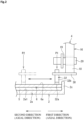
- FIG. 1 illustrates an example of a tire evaluation apparatus used for forming a snow surface for tire evaluation.
- a tire evaluation apparatus 1 illustrated in FIG. 1 has a drum 2 having an inner circumferential side on which a tire T runs, and a support mechanism 4 for supporting the tire T on the inner surface side of the drum 2. That is, the tire evaluation apparatus 1 is a so-called inside drum-type evaluation apparatus.
- the drum 2 is supported by a driving mechanism (not illustrated).
- the drum 2 includes a cylindrical portion 2a, a disk-shaped portion 2b, and an annular portion 2c.
- the cylindrical portion 2a has a horizontal center axis C.
- the center axis C is horizontal.
- the drum 2 and the support mechanism 4 are aligned along the center axis C.
- the direction parallel to the center axis C is referred to as axial direction
- the direction from the drum 2 side toward the support mechanism 4 side in the axial direction is referred to as first direction
- the direction from the support mechanism 4 side toward the drum 2 side in the axial direction is referred to as second direction.
- a base layer 5 and a compressed snow layer 6 are disposed on an inner circumferential surface 2a1 of the cylindrical portion 2a.
- the base layer 5 and the compressed snow layer 6 will be described below.
- the disk-shaped portion 2b closes an opening, at the second direction side, of the cylindrical portion 2a.
- a shaft portion 3 is disposed at an outer surface 2b 1, at the second direction side, of the disk-shaped portion 2b.
- the axial center of the shaft portion 3 coincides with the center axis C.
- the driving mechanism holds the shaft portion 3, and drives the drum 2 so as to rotate the drum 2 around the center axis C of the cylindrical portion 2a.
- the annular portion 2c is disposed along the edge of the opening, at the first direction side, of the cylindrical portion 2a.
- the annular portion 2c protrudes radially inward from the edge of the cylindrical portion 2a.
- the annular portion 2c is in contact with the side surfaces, at the first direction side, of the base layer 5 and the compressed snow layer 6.
- the annular portion 2c restricts movement of the base layer 5 and the compressed snow layer 6 in the axial direction.
- the tire T and a part of the support mechanism 4 are inserted into the cylindrical portion 2a through the inner circumferential side of the annular portion 2c, and are disposed inside the cylindrical portion 2a.
- the support mechanism 4 includes a base 10, a column 12, a horizontal arm 14, and an up-down extending arm 16.
- the base 10 has a track 10a, a base body 10b, and an actuator 10c.
- the base body 10b can be horizontally moved on the track 10a along the axial direction.
- the actuator 10c has a shaft 10c1 that can be moved forward and backward in the axial direction.
- the end of the shaft 10c1 is connected to the base body 10b.
- the actuator 10c can move the base body 10b in the horizontal direction by moving the shaft 10c1 forward and backward.
- the column 12 is a column-like member that extends in the up-down direction, and is disposed on the upper surface of the base body 10b.
- the horizontal arm 14 is disposed at the end of the column 12.
- the horizontal arm 14 extends horizontally from the column 12 toward the drum 2.
- the up-down extending arm 16 is disposed at the end of the horizontal arm 14.
- the up-down extending arm 16 includes an actuator 17, an arm body 18, a rotary shaft 19, and a motor 20.
- the actuator 17 is fixed to the end of the horizontal arm 14.
- the actuator 17 has a shaft 17a that can be moved upward and downward in the up-down direction.
- the arm body 18, the rotary shaft 19, and the motor 20 are fixed to the shaft 17a.
- the actuator 17 moves the arm body 18, the rotary shaft 19, and the motor 20 in the up-down direction by moving the shaft 17a upward and downward.
- the arm body 18 is fixed to the lower end of the shaft 17a.
- the arm body 18 extends in the up-down direction.
- the rotary shaft 19 and the motor 20 are disposed at the lower end of the arm body 18.
- the rotary shaft 19 is rotatably supported by the arm body 18 through a bearing or the like.
- the rotary shaft 19 is supported so as to be parallel to the axial direction.
- the rotary shaft 19 is disposed just below the center axis C.
- the tire T is fixed integrally to the end, at the second direction side, of the rotary shaft 19. Therefore, both the tire T and the rotary shaft 19 are rotatably supported by the arm body 18.
- the motor 20 drives the rotary shaft 19 so as to rotate the rotary shaft 19.
- the motor 20 allows a rotation speed of the tire T to be adjusted in the evaluation test.
- the support mechanism 4 having the above-described configuration can move the tire T in the up-down direction by using the actuator 17.
- the support mechanism 4 can move the tire T in the axial direction by using the actuator 10c of the base 10.
- the support mechanism 4 can move the tire T disposed outside the drum 2 along the second direction, and dispose the tire T in the drum 2. Furthermore, the support mechanism 4 can move the tire T downward, and bring the tire T into contact with the compressed snow layer 6.
- the base layer 5 is an ice layer disposed on the inner circumferential surface 2a1 of the cylindrical portion 2a.
- the compressed snow layer 6 is stacked on the inner circumferential surface of the base layer 5.
- the compressed snow layer 6 is formed by stacking snow made by an artificial snow making machine, onto the inner circumferential surface of the base layer 5, and compressing the snow outward in the radial direction.
- a surface 6a, on the inner circumferential side, of the compressed snow layer 6 has a snow surface 7 for tire evaluation.
- the snow surface 7 for tire evaluation (hereinafter, simply referred to also as snow surface 7 for evaluation) is formed by a method for forming a snow surface for tire evaluation as described below.
- the up-down extending arm 16 further includes a load measurement device 22.
- the load measurement device 22 measures a load that acts on the tire T.
- the load measurement device 22 includes, for example, a plurality of load sensors disposed on the outer circumferential side of the rotary shaft 19. The plurality of load sensors are equally spaced from each other along the outer circumference of the rotary shaft 19, and each output information indicating a load which acts on the rotary shaft 19.
- the output of the load measurement device 22 is supplied to a controller for controlling the tire evaluation apparatus 1.
- the controller controls the actuator 17 and adjusts a load that acts on the tire T, based on the output of the load measurement device 22.
- the tire evaluation apparatus 1 has a first rotation speed sensor and a second rotation speed sensor (both of which are not illustrated) for detecting a rotation speed of the rotary shaft 19 and a rotation speed of the drum 2.
- These rotation sensors may be implemented by a Hall sensor of the motor or may be independently disposed in the motor.
- the controller has a function of controlling driving mechanisms of the actuator 10c, the motor 20, and the drum 2 in addition to the actuator 17.
- the controller controls each of the units based on the output of the load measurement device 22 and outputs of the first rotation speed sensor and the second rotation speed sensor.
- the controller can control each of the units according to preset conditions, bring the tire T into contact with the snow surface 7 for evaluation in the compressed snow layer 6, and perform test running of the tire T.
- the controller can be operated by an operator of the tire evaluation apparatus 1.
- the operator can discretionarily control and operate the driving mechanisms of the actuator 17, the actuator 10c, the motor 20, and the drum 2.
- the method for forming a snow surface for tire evaluation includes a first step of disposing a cutting blade for cutting the compressed snow layer 6 at the support mechanism 4 for supporting the tire T, a second step of bringing the cutting blade into contact with the surface 6a of the compressed snow layer 6 so as to dispose the end of the cutting blade at a predetermined depth from the surface of the compressed snow layer 6, and moving the cutting blade between a first position and a second position of the surface 6a of the compressed snow layer 6 in parallel with the width direction of the compressed snow layer 6 while rotating the drum 2 at a predetermined circumferential speed, and a third step of repeating the second step until the compressed snow layer 6 has a predetermined thickness.
- the snow surface 7 for evaluation is formed on the surface 6a, on the inner circumferential side, of the compressed snow layer 6.
- the base layer 5 and the compressed snow layer 6 are provided on the inner circumferential surface 2a1 of the cylindrical portion 2a.
- snow made by an artificial snow making machine is stacked on the inner circumferential surface of the base layer 5.
- the snow is evenly stacked in the circumferential direction.
- the snow stacked on the inner circumferential surface of the base layer 5 is compressed by the tire T. That is, after snow is stacked on the inner circumferential surface of the base layer 5, the tire T is caused to run on the stacked snow. Thus, the snow on the inner circumferential surface of the base layer 5 is compressed to form the compressed snow layer 6.
- FIG. 2 illustrates the steps of forming the snow surface 7 for evaluation.
- FIG. 2 illustrates a portion near the end of the arm body 18 (up-down extending arm 16) in FIG. 1 .
- an operator firstly fixes a cutting blade 32 to the arm body 18 of the support mechanism 4.
- a bracket 30 extending from the arm body 18 in the second direction is fixed at the lower end portion of the arm body 18.
- the bracket 30 is a bar-like member for fixing the cutting blade 32.
- the end, at the first direction side, of the bracket 30 is fixed to the arm body 18.
- the cutting blade 32 is fixed to the end, at the second direction side, of the bracket 30.
- the cutting blade 32 is, for example, fixed by a clamp or the like disposed at the end of the bracket 30.
- the cutting blade 32 has a shank 32b and a cutting edge 32a.
- the shank 32b is a bar-like portion, and is fixed by the bracket 30 such that the longitudinal direction of the shank 32b is along the up-down direction.
- the cutting edge 32a has a rectangular shape in which the end thereof is parallel to the axial direction.
- the cutting blade 32 is, for example, a flat cutting tool for machining.
- the bracket 30 and the cutting blade 32 are fixed to the lower end portion of the arm body 18 from which the tire T has been dismounted.
- the cutting blade 32 is disposed at the arm body 18, and can thus be moved parallel to the axial direction (width direction of the compressed snow layer 6) and the up-down direction by the support mechanism 4.
- the operator moves the cutting blade 32 to the first position P1, and the process is shifted to the second step.
- the first position P1 is a position on the surface 6a of the compressed snow layer 6 in the width direction of the compressed snow layer 6. As illustrated in FIG. 2 , the first position P1 is a predetermined position near the end, at the first direction side, of the compressed snow layer 6. The first position P1 is set so as to position the cutting blade 32 close to the annular portion 2c as much as possible.
- FIG. 2 illustrates a state where the cutting blade 32 has already been positioned at the first position.
- the operator When the cutting blade 32 has been moved to the first position P1, the operator operates the actuator 17 to move the cutting blade 32 downward and bring the cutting blade 32 into contact with the compressed snow layer 6.
- FIG. 3 illustrates a state where the cutting blade 32 is brought into contact with the compressed snow layer 6.
- the cutting blade 32 is held so as to be inserted into the compressed snow layer 6 such that an end 32a1 of the cutting edge 32a is disposed at a predetermined depth D from the surface 6a of the compressed snow layer 6.
- the surface 6a is a surface that has been compressed during forming of the compressed snow layer 6.
- the operator performs parallel movement of the cutting blade 32 from the first position P1 to the second position P2 in the width direction of the compressed snow layer 6 at a predetermined moving speed V2 while rotating the drum 2 such that a circumferential speed of the inner circumferential surface 2a1 of the drum 2 is a predetermined circumferential speed V1.
- the second position P2 is a position on the surface 6a of the compressed snow layer 6 in the width direction of the compressed snow layer 6, similarly to the first position P1.
- the second position P2 is a predetermined position that is closer to the end, at the second direction side, of the compressed snow layer 6 than to the end, at the first direction side, of the compressed snow layer 6.
- the second position P2 is set so as to position the cutting blade 32 close to the disk-shaped portion 2b ( FIG. 1 ) as much as possible.
- the end 32a1 of the cutting edge 32a is inserted in the compressed snow layer 6 so as to be disposed at the predetermined depth D from the surface 6a of the compressed snow layer 6. Therefore, when the drum 2 is rotated, the surface 6a of the compressed snow layer 6 is cut by the cutting blade 32.
- the cut trace is helically formed without forming gaps in the axial direction. Therefore, the surface 6a of the compressed snow layer 6 can be evenly cut.
- the cut surface is formed by such a cut trace on the surface 6a of the compressed snow layer 6.
- the circumferential speed V1 of the drum 2 and the moving speed V2 of the cutting blade 32 are appropriately set such that the cut trace is helically formed without forming gaps in the axial direction.
- the cutting blade 32 is brought into contact with the surface 6a of the compressed snow layer 6 such that the end 32a1 of the cutting blade 32 is disposed at the predetermined depth D from the surface 6a of the compressed snow layer 6, and the cutting blade 32 is moved between the first position P1 and the second position P2 of the surface 6a of the compressed snow layer 6 in parallel with the width direction of the compressed snow layer 6 while the drum 2 is rotated at a predetermined speed.
- the operator operates the actuator 17 to further move the cutting blade 32 downward, and insert the cutting blade 32 into the compressed snow layer 6.
- the cutting blade 32 is held so as to be inserted in the compressed snow layer 6 such that the end 32a1 is disposed at the predetermined depth D from the cut surface in the surface 6a of the compressed snow layer 6.
- the operator performs parallel movement of the cutting blade 32 from the second position P2 to the first position P1 in the width direction of the compressed snow layer 6 at the predetermined moving speed V2 while rotating the drum 2 such that the circumferential speed of the inner circumferential surface 2a1 of the drum 2 is the circumferential speed V1.
- the operator causes the cutting blade 32 to reciprocate in the axial direction, and thus, the second step is repeatedly performed.
- the operator halts repeating the second step. That is, the operator performs the third step of repeating the second step until the compressed snow layer 6 has a predetermined thickness.
- the cut surface in the surface 6a of the compressed snow layer 6 that has the predetermined thickness becomes the snow surface 7 for evaluation.
- the operator moves the cutting blade 32 from the inner circumferential side of the drum 2 to outside of the drum 2, and removes snow which has been cut out by the cutting blade 32 from the inside of the drum 2 to outside of the drum 2.
- the cut snow can be inhibited from affecting the tire evaluation.
- the snow surface 7 for evaluation is formed at the surface 6a of the compressed snow layer 6.
- the snow surface 7 for evaluation can be formed by cutting the surface 6a of the compressed snow layer 6 by the cutting blade 32 disposed at the support mechanism 4. Therefore, a mechanism or the like for providing the cutting blade 32 need not be added, and the even snow surface 7, for evaluation, in which unevenness is reduced can be formed by appropriately adjusting the cutting conditions.
- the predetermined depth D is preferably 0.3 mm or more and 5.0 mm or less.
- the predetermined depth D is less than 0.3 mm, a cut amount of the compressed snow layer 6 is reduced, and a time required for forming the snow surface 7 for evaluation becomes long. If the predetermined depth is more than 5.0 mm, a cut amount of the compressed snow layer 6 becomes relatively great, and adjustment of the thickness of the compressed snow layer 6 may become difficult.
- the snow surface 7 for evaluation can be appropriately formed.
- the distance from the first position P1 to the second position P2 is preferably 1000 mm or more and 3000 mm or less.
- the snow surface 7 for evaluation can be appropriately formed.
- the predetermined circumferential speed V1 is preferably 30 km/h or higher and 100 km/h or lower.
- the circumferential speed V1 is lower than 30 km/h, a time required for forming the snow surface 7 for evaluation becomes long. If the circumferential speed V1 is higher than 100 km/h, an adjustment allowance of the moving speed V2 for parallel movement of the cutting blade 32 in the width direction is reduced, and appropriate setting of the cutting condition becomes difficult. In a case where the circumferential speed V1 of the drum 2 is 30 km/h or higher and 100 km/h or lower, the snow surface 7 for evaluation can be appropriately formed in a short time period.
- the moving speed V2 of the cutting blade 32 is preferably 5 mm/s or higher and 40 mm/s or lower.
- the moving speed V2 is lower than 5 mm/s, the circumferential speed V1 of the drum 2 needs to be significantly reduced in some cases, and a time required for forming the snow surface 7 for evaluation becomes long. If the moving speed V2 is higher than 40 mm/s, the circumferential speed V1 of the drum needs to be significantly increased in some cases, and appropriate setting of the cutting condition becomes difficult. In a case where the moving speed V2 of the cutting blade 32 is 5 mm/s or higher and 40 mm/s or lower, the snow surface 7 for evaluation can be appropriately formed in a short time period.
- a flat cutting tool for machining is used as the cutting blade 32 .
- the present invention is not limited to this example.
- a metal piece having a sharp tip may be used as long as the surface 6a of the compressed snow layer 6 can be flatly cut.
- the snow surface for evaluation according to the example was formed in the compressed snow layer 6 in the drum 2 under the following conditions.
- the snow surface for evaluation according to the comparative example was formed in the drum 2 in the following procedure.
- the tire T that was caused to run on the snow surface for evaluation was the same between the example and the comparative example.
- the tire T was caused to run and a relationship between a coefficient of friction and a sliding speed was obtained.
- FIG. 4 shows a graph representing a relationship between a coefficient of friction and a sliding speed.
- the horizontal axis represents sliding speeds
- the vertical axis represents coefficients of friction.
- the sliding speed represents a difference in speed between the tire and the snow surface for evaluation. That is, the sliding speed represents a difference between the circumferential speed V1 of the drum 2 and the tire circumferential speed.
- the coefficient of friction was obtained by using output of the load measurement device 22 for measuring a load acting on the tire, and outputs of the first rotation speed sensor and the second rotation speed sensor.
Landscapes
- Physics & Mathematics (AREA)
- General Physics & Mathematics (AREA)
- Tires In General (AREA)
Abstract
Description
- The present invention relates to a method for forming a snow surface for tire evaluation.
- For evaluating tire performance on a snow surface, in addition to the evaluation being performed outdoors, an artificial snow surface may be provided indoors to evaluate tire performance on the artificial snow surface.
Japanese Laid-Open Patent Publication (translation of PCT application) No. 2005-515110 - An object of the present invention is to provide a technique capable of forming an even snow surface in which unevenness is reduced.
- (1) A method for forming a snow surface for tire evaluation according to the present invention is directed to a method for forming a snow surface for tire evaluation in which the snow surface for tire evaluation is formed on a surface of a compressed snow layer disposed at an inner surface of a drum. The forming method includes: a first step of disposing a cutting blade for cutting the compressed snow layer, at a support mechanism for supporting a tire that runs on an inner surface side of the drum; a second step of bringing the cutting blade into contact with the compressed snow layer so as to dispose an end of the cutting blade at a predetermined depth from the surface of the compressed snow layer, and moving the cutting blade between a first position and a second position of the surface of the compressed snow layer in parallel with a width direction of the compressed snow layer while rotating the drum at a predetermined circumferential speed; and a third step of repeating the second step until the compressed snow layer has a predetermined thickness.
- In this configuration, the snow surface for tire evaluation can be formed by cutting the surface of the compressed snow layer with the cutting blade disposed at the support mechanism. Therefore, a mechanism or the like for providing the cutting blade need not be added, and the even snow surface in which unevenness is reduced can be formed by appropriately adjusting the cutting conditions.
- (2) Preferably, the above-described method for forming a snow surface for tire evaluation further includes a step of removing, after the third step, snow which has been cut out by the cutting blade.
- In this case, the cut snow can be inhibited from affecting tire evaluation.
- (3) In the above-described method for forming a snow surface for tire evaluation, preferably, a cutting trace is helically formed by the cutting blade without forming gaps in an axial direction.
- In this case, the surface of the compressed snow layer can be evenly cut.
- (4) In the above-described method for forming a snow surface for tire evaluation, the predetermined depth is preferably 0.3 mm or more and 5.0 mm or less.
- If the predetermined depth is less than 0.3 mm, a cut amount of the compressed snow layer is reduced, and a time required for forming the snow surface for evaluation becomes long. If the predetermined depth is more than 5.0 mm, a cut amount of the compressed snow layer becomes relatively great, and adjustment of the thickness of the compressed snow layer may become difficult.
- In a case where the predetermined depth is 0.3 mm or more and 5.0 mm or less, the snow surface for evaluation can be appropriately formed.
- (5) In the above-described method for forming a snow surface for tire evaluation, a distance from the first position to the second position is preferably 1000 mm or more and 3000 mm or less.
- If the distance from the first position to the second position is less than 1000 mm, the snow surface cannot be sufficiently obtained for the tire evaluation. If the distance from the first position to the second position is more than 3000 mm, a time required for forming the snow surface for evaluation becomes long. In a case where the distance from the first position to the second position is 1000 mm or more and 3000 mm or less, the snow surface for evaluation can be appropriately formed.
- (6) In the above-described method for forming a snow surface for tire evaluation, the predetermined circumferential speed is preferably 30 km/h or higher and 100 km/h or lower.
- If the circumferential speed is lower than 30 km/h, a time required for forming the snow surface for evaluation becomes long. If the circumferential speed is higher than 100 km/h, an adjustment allowance of the speed for parallel movement of the cutting blade in the width direction is reduced, and appropriate setting of the cutting condition becomes difficult. In a case where the circumferential speed of the drum is 30 km/h or higher and 100 km/h or lower, the snow surface for evaluation can be appropriately formed in a short time period.
- (7) In the above-described method for forming a snow surface for tire evaluation, a moving speed of the cutting blade is preferably 5 mm/s or higher and 40 mm/s or lower.
- If the moving speed is lower than 5 mm/s, the circumferential speed of the drum needs to be significantly reduced in some cases, and a time required for forming the snow surface for evaluation becomes long. If the moving speed is higher than 40 mm/s, the circumferential speed of the drum needs to be significantly increased in some cases, and appropriate setting of the cutting condition becomes difficult. In a case where the moving speed of the cutting blade is 5 mm/s or higher and 40 mm/s or lower, the snow surface for evaluation can be appropriately formed in a short time period.
- According to the present invention, the even snow surface for tire evaluation in which unevenness is reduced can be formed.
-
-
FIG. 1 illustrates an example of a tire evaluation apparatus used for forming a snow surface for tire evaluation; -
FIG. 2 illustrates steps of forming a snow surface for evaluation; -
FIG. 3 illustrates a state where a cutting blade is brought into contact with a compressed snow layer; -
FIG. 4 shows a graph representing a relationship between a coefficient of friction and a sliding speed; -
FIG. 5(a) illustrates an example of a plurality of teeth of a sled of conventional art; and -
FIG. 5(b) illustrates an example of a snow surface that has become uneven. - In the conventional art disclosed in
Japanese Laid-Open Patent Publication (translation of PCT application) No. 2005-515110 -
FIG. 5(a) illustrates an example of a plurality of teeth of a sled of conventional art. - In
FIG. 5(a) , a plurality ofteeth 100 are disposed at anedge member 102 on the rear side of the sled. The plurality ofteeth 100 protrude from alower surface 102a of theedge member 102. The plurality ofteeth 100 are arranged in a line at thelower surface 102a. The plurality ofteeth 100 are provided so as to enter the snow surface over several centimeters. - The sled (edge member 102) travels in the direction (direction indicated by an arrow in
FIG. 5(a) ) orthogonal to the longitudinal direction of theedge member 102. - At this time, the plurality of teeth dig up the snow surface, and the snow surface becomes uneven.
-
FIG. 5(b) illustrates an example of a snow surface that has become uneven. As illustrated inFIG. 5(b) , asnow surface 104a of acompressed snow layer 104 hassmooth portions 105 andrecesses 106. Thesmooth portion 105 is a surface that has been made smooth by compressing snow. Therecess 106 is a portion recessed from thesmooth portion 105. Therecess 106 is formed into a groove-like shape along the sled traveling direction by digging up the snow surface by the plurality ofteeth 100. - If a snow surface for evaluation has such unevenness, this may cause reduction of accuracy of a tire evaluation test. Therefore, a technique of forming an even snow surface in which the unevenness is reduced has been desired.
- A preferred embodiment will be described below with reference to the drawings.
-
FIG. 1 illustrates an example of a tire evaluation apparatus used for forming a snow surface for tire evaluation. - A
tire evaluation apparatus 1 illustrated inFIG. 1 has adrum 2 having an inner circumferential side on which a tire T runs, and asupport mechanism 4 for supporting the tire T on the inner surface side of thedrum 2. That is, thetire evaluation apparatus 1 is a so-called inside drum-type evaluation apparatus. - The
drum 2 is supported by a driving mechanism (not illustrated). Thedrum 2 includes acylindrical portion 2a, a disk-shaped portion 2b, and anannular portion 2c. - The
cylindrical portion 2a has a horizontal center axis C. The center axis C is horizontal. Thedrum 2 and thesupport mechanism 4 are aligned along the center axis C. - In the following description, the direction parallel to the center axis C is referred to as axial direction, the direction from the
drum 2 side toward thesupport mechanism 4 side in the axial direction is referred to as first direction, and the direction from thesupport mechanism 4 side toward thedrum 2 side in the axial direction is referred to as second direction. - On an inner circumferential surface 2a1 of the
cylindrical portion 2a, abase layer 5 and acompressed snow layer 6 are disposed Thebase layer 5 and thecompressed snow layer 6 will be described below. - The disk-shaped
portion 2b closes an opening, at the second direction side, of thecylindrical portion 2a. Ashaft portion 3 is disposed at anouter surface 2bportion 2b. The axial center of theshaft portion 3 coincides with the center axis C. The driving mechanism holds theshaft portion 3, and drives thedrum 2 so as to rotate thedrum 2 around the center axis C of thecylindrical portion 2a. - The
annular portion 2c is disposed along the edge of the opening, at the first direction side, of thecylindrical portion 2a. Theannular portion 2c protrudes radially inward from the edge of thecylindrical portion 2a. Theannular portion 2c is in contact with the side surfaces, at the first direction side, of thebase layer 5 and thecompressed snow layer 6. Thus, theannular portion 2c restricts movement of thebase layer 5 and thecompressed snow layer 6 in the axial direction. - The tire T and a part of the
support mechanism 4 are inserted into thecylindrical portion 2a through the inner circumferential side of theannular portion 2c, and are disposed inside thecylindrical portion 2a. - The
support mechanism 4 includes abase 10, acolumn 12, ahorizontal arm 14, and an up-down extendingarm 16. - The
base 10 has atrack 10a, abase body 10b, and anactuator 10c. Thebase body 10b can be horizontally moved on thetrack 10a along the axial direction. Theactuator 10c has a shaft 10c1 that can be moved forward and backward in the axial direction. The end of the shaft 10c1 is connected to thebase body 10b. Theactuator 10c can move thebase body 10b in the horizontal direction by moving the shaft 10c1 forward and backward. - The
column 12 is a column-like member that extends in the up-down direction, and is disposed on the upper surface of thebase body 10b. Thehorizontal arm 14 is disposed at the end of thecolumn 12. - The
horizontal arm 14 extends horizontally from thecolumn 12 toward thedrum 2. - The up-down extending
arm 16 is disposed at the end of thehorizontal arm 14. - The up-down extending
arm 16 includes anactuator 17, anarm body 18, arotary shaft 19, and amotor 20. - The
actuator 17 is fixed to the end of thehorizontal arm 14. Theactuator 17 has ashaft 17a that can be moved upward and downward in the up-down direction. Thearm body 18, therotary shaft 19, and themotor 20 are fixed to theshaft 17a. Theactuator 17 moves thearm body 18, therotary shaft 19, and themotor 20 in the up-down direction by moving theshaft 17a upward and downward. - The
arm body 18 is fixed to the lower end of theshaft 17a. Thearm body 18 extends in the up-down direction. - The
rotary shaft 19 and themotor 20 are disposed at the lower end of thearm body 18. - The
rotary shaft 19 is rotatably supported by thearm body 18 through a bearing or the like. Therotary shaft 19 is supported so as to be parallel to the axial direction. - The
rotary shaft 19 is disposed just below the center axis C. - The tire T is fixed integrally to the end, at the second direction side, of the
rotary shaft 19. Therefore, both the tire T and therotary shaft 19 are rotatably supported by thearm body 18. - The
motor 20 drives therotary shaft 19 so as to rotate therotary shaft 19. Themotor 20 allows a rotation speed of the tire T to be adjusted in the evaluation test. - The
support mechanism 4 having the above-described configuration can move the tire T in the up-down direction by using theactuator 17. Thesupport mechanism 4 can move the tire T in the axial direction by using theactuator 10c of thebase 10. - Therefore, the
support mechanism 4 can move the tire T disposed outside thedrum 2 along the second direction, and dispose the tire T in thedrum 2. Furthermore, thesupport mechanism 4 can move the tire T downward, and bring the tire T into contact with thecompressed snow layer 6. - The
base layer 5 is an ice layer disposed on the inner circumferential surface 2a1 of thecylindrical portion 2a. Thecompressed snow layer 6 is stacked on the inner circumferential surface of thebase layer 5. - The
compressed snow layer 6 is formed by stacking snow made by an artificial snow making machine, onto the inner circumferential surface of thebase layer 5, and compressing the snow outward in the radial direction. - A
surface 6a, on the inner circumferential side, of the compressedsnow layer 6 has asnow surface 7 for tire evaluation. Thesnow surface 7 for tire evaluation (hereinafter, simply referred to also assnow surface 7 for evaluation) is formed by a method for forming a snow surface for tire evaluation as described below. - The up-down extending
arm 16 further includes aload measurement device 22. Theload measurement device 22 measures a load that acts on the tire T. Theload measurement device 22 includes, for example, a plurality of load sensors disposed on the outer circumferential side of therotary shaft 19. The plurality of load sensors are equally spaced from each other along the outer circumference of therotary shaft 19, and each output information indicating a load which acts on therotary shaft 19. The output of theload measurement device 22 is supplied to a controller for controlling thetire evaluation apparatus 1. The controller controls theactuator 17 and adjusts a load that acts on the tire T, based on the output of theload measurement device 22. - Furthermore, the
tire evaluation apparatus 1 has a first rotation speed sensor and a second rotation speed sensor (both of which are not illustrated) for detecting a rotation speed of therotary shaft 19 and a rotation speed of thedrum 2. These rotation sensors may be implemented by a Hall sensor of the motor or may be independently disposed in the motor. - The controller has a function of controlling driving mechanisms of the
actuator 10c, themotor 20, and thedrum 2 in addition to theactuator 17. The controller controls each of the units based on the output of theload measurement device 22 and outputs of the first rotation speed sensor and the second rotation speed sensor. - The controller can control each of the units according to preset conditions, bring the tire T into contact with the
snow surface 7 for evaluation in thecompressed snow layer 6, and perform test running of the tire T. - The controller can be operated by an operator of the
tire evaluation apparatus 1. The operator can discretionarily control and operate the driving mechanisms of theactuator 17, theactuator 10c, themotor 20, and thedrum 2. - [Method for forming snow surface for tire evaluation]
- Next, a method for forming a snow surface for tire evaluation will be described.
- The method for forming a snow surface for tire evaluation according to the present embodiment includes a first step of disposing a cutting blade for cutting the
compressed snow layer 6 at thesupport mechanism 4 for supporting the tire T, a second step of bringing the cutting blade into contact with thesurface 6a of the compressedsnow layer 6 so as to dispose the end of the cutting blade at a predetermined depth from the surface of the compressedsnow layer 6, and moving the cutting blade between a first position and a second position of thesurface 6a of the compressedsnow layer 6 in parallel with the width direction of the compressedsnow layer 6 while rotating thedrum 2 at a predetermined circumferential speed, and a third step of repeating the second step until thecompressed snow layer 6 has a predetermined thickness. - As described above, the
snow surface 7 for evaluation is formed on thesurface 6a, on the inner circumferential side, of the compressedsnow layer 6. - Firstly, the
base layer 5 and thecompressed snow layer 6 are provided on the inner circumferential surface 2a1 of thecylindrical portion 2a. - After the
base layer 5 of ice is provided on the inner circumferential surface 2a1, snow made by an artificial snow making machine is stacked on the inner circumferential surface of thebase layer 5. The snow is evenly stacked in the circumferential direction. - The snow stacked on the inner circumferential surface of the
base layer 5 is compressed by the tire T. That is, after snow is stacked on the inner circumferential surface of thebase layer 5, the tire T is caused to run on the stacked snow. Thus, the snow on the inner circumferential surface of thebase layer 5 is compressed to form thecompressed snow layer 6. - Thereafter, the above-described first step is performed.
-
FIG. 2 illustrates the steps of forming thesnow surface 7 for evaluation. -
FIG. 2 illustrates a portion near the end of the arm body 18 (up-down extending arm 16) inFIG. 1 . - In the first step, an operator firstly fixes a
cutting blade 32 to thearm body 18 of thesupport mechanism 4. - A
bracket 30 extending from thearm body 18 in the second direction is fixed at the lower end portion of thearm body 18. Thebracket 30 is a bar-like member for fixing thecutting blade 32. The end, at the first direction side, of thebracket 30 is fixed to thearm body 18. Thecutting blade 32 is fixed to the end, at the second direction side, of thebracket 30. - The
cutting blade 32 is, for example, fixed by a clamp or the like disposed at the end of thebracket 30. - The
cutting blade 32 has ashank 32b and acutting edge 32a. Theshank 32b is a bar-like portion, and is fixed by thebracket 30 such that the longitudinal direction of theshank 32b is along the up-down direction. Thecutting edge 32a has a rectangular shape in which the end thereof is parallel to the axial direction. - The
cutting blade 32 is, for example, a flat cutting tool for machining. - Thus, in the first step, the
bracket 30 and thecutting blade 32 are fixed to the lower end portion of thearm body 18 from which the tire T has been dismounted. - The
cutting blade 32 is disposed at thearm body 18, and can thus be moved parallel to the axial direction (width direction of the compressed snow layer 6) and the up-down direction by thesupport mechanism 4. - After the
cutting blade 32 has been fixed (first step), the operator moves thecutting blade 32 to the first position P1, and the process is shifted to the second step. - The first position P1 is a position on the
surface 6a of the compressedsnow layer 6 in the width direction of the compressedsnow layer 6. As illustrated inFIG. 2 , the first position P1 is a predetermined position near the end, at the first direction side, of the compressedsnow layer 6. The first position P1 is set so as to position thecutting blade 32 close to theannular portion 2c as much as possible. -
FIG. 2 illustrates a state where thecutting blade 32 has already been positioned at the first position. - When the
cutting blade 32 has been moved to the first position P1, the operator operates theactuator 17 to move thecutting blade 32 downward and bring thecutting blade 32 into contact with thecompressed snow layer 6. -
FIG. 3 illustrates a state where thecutting blade 32 is brought into contact with thecompressed snow layer 6. - As illustrated in
FIG. 3 , thecutting blade 32 is held so as to be inserted into thecompressed snow layer 6 such that an end 32a1 of thecutting edge 32a is disposed at a predetermined depth D from thesurface 6a of the compressedsnow layer 6. - At this stage, the
surface 6a is a surface that has been compressed during forming of the compressedsnow layer 6. - Subsequently, the operator performs parallel movement of the
cutting blade 32 from the first position P1 to the second position P2 in the width direction of the compressedsnow layer 6 at a predetermined moving speed V2 while rotating thedrum 2 such that a circumferential speed of the inner circumferential surface 2a1 of thedrum 2 is a predetermined circumferential speed V1. - As illustrated in
FIG. 2 , the second position P2 is a position on thesurface 6a of the compressedsnow layer 6 in the width direction of the compressedsnow layer 6, similarly to the first position P1. The second position P2 is a predetermined position that is closer to the end, at the second direction side, of the compressedsnow layer 6 than to the end, at the first direction side, of the compressedsnow layer 6. The second position P2 is set so as to position thecutting blade 32 close to the disk-shapedportion 2b (FIG. 1 ) as much as possible. - At this time, the end 32a1 of the
cutting edge 32a is inserted in thecompressed snow layer 6 so as to be disposed at the predetermined depth D from thesurface 6a of the compressedsnow layer 6. Therefore, when thedrum 2 is rotated, thesurface 6a of the compressedsnow layer 6 is cut by thecutting blade 32. - Furthermore, since the
cutting blade 32 is moved parallel to the width direction of the compressedsnow layer 6, a cut trace is formed helically with the width of the end 32a1 of thecutting edge 32a, on thesurface 6a, by thecutting blade 32. - The cut trace is helically formed without forming gaps in the axial direction. Therefore, the
surface 6a of the compressedsnow layer 6 can be evenly cut. - The cut surface is formed by such a cut trace on the
surface 6a of the compressedsnow layer 6. - The circumferential speed V1 of the
drum 2 and the moving speed V2 of thecutting blade 32 are appropriately set such that the cut trace is helically formed without forming gaps in the axial direction. - When the
cutting blade 32 reaches the second position P2, the second step ends. - Thus, in the second step, the
cutting blade 32 is brought into contact with thesurface 6a of the compressedsnow layer 6 such that the end 32a1 of thecutting blade 32 is disposed at the predetermined depth D from thesurface 6a of the compressedsnow layer 6, and thecutting blade 32 is moved between the first position P1 and the second position P2 of thesurface 6a of the compressedsnow layer 6 in parallel with the width direction of the compressedsnow layer 6 while thedrum 2 is rotated at a predetermined speed. - Subsequently, the operator operates the
actuator 17 to further move thecutting blade 32 downward, and insert thecutting blade 32 into thecompressed snow layer 6. Thecutting blade 32 is held so as to be inserted in thecompressed snow layer 6 such that the end 32a1 is disposed at the predetermined depth D from the cut surface in thesurface 6a of the compressedsnow layer 6. - Subsequently, the operator performs parallel movement of the
cutting blade 32 from the second position P2 to the first position P1 in the width direction of the compressedsnow layer 6 at the predetermined moving speed V2 while rotating thedrum 2 such that the circumferential speed of the inner circumferential surface 2a1 of thedrum 2 is the circumferential speed V1. - That is, the operator causes the
cutting blade 32 to reciprocate in the axial direction, and thus, the second step is repeatedly performed. - When the
compressed snow layer 6 is determined to have a predetermined thickness, the operator halts repeating the second step. That is, the operator performs the third step of repeating the second step until thecompressed snow layer 6 has a predetermined thickness. - The cut surface in the
surface 6a of the compressedsnow layer 6 that has the predetermined thickness becomes thesnow surface 7 for evaluation. - When the
compressed snow layer 6 has the predetermined thickness and the third step is ended, the operator moves thecutting blade 32 from the inner circumferential side of thedrum 2 to outside of thedrum 2, and removes snow which has been cut out by thecutting blade 32 from the inside of thedrum 2 to outside of thedrum 2. - Thus, the cut snow can be inhibited from affecting the tire evaluation.
- Thus, the
snow surface 7 for evaluation is formed at thesurface 6a of the compressedsnow layer 6. - In the above-described configuration, the
snow surface 7 for evaluation can be formed by cutting thesurface 6a of the compressedsnow layer 6 by thecutting blade 32 disposed at thesupport mechanism 4. Therefore, a mechanism or the like for providing thecutting blade 32 need not be added, and theeven snow surface 7, for evaluation, in which unevenness is reduced can be formed by appropriately adjusting the cutting conditions. - The predetermined depth D is preferably 0.3 mm or more and 5.0 mm or less.
- If the predetermined depth D is less than 0.3 mm, a cut amount of the compressed
snow layer 6 is reduced, and a time required for forming thesnow surface 7 for evaluation becomes long. If the predetermined depth is more than 5.0 mm, a cut amount of the compressedsnow layer 6 becomes relatively great, and adjustment of the thickness of the compressedsnow layer 6 may become difficult. - In a case where the predetermined depth is 0.3 mm or more and 5.0 mm or less, the
snow surface 7 for evaluation can be appropriately formed. - The distance from the first position P1 to the second position P2 is preferably 1000 mm or more and 3000 mm or less.
- If the distance from the first position P1 to the second position P2 is less than 1000 mm, the snow surface cannot be sufficiently obtained for the tire evaluation. If the distance from the first position P1 to the second position P2 is more than 3000 mm, a time required for forming the
snow surface 7 for evaluation becomes long. In a case where the distance from the first position P1 to the second position P2 is 1000 mm or more and 3000 mm or less, thesnow surface 7 for evaluation can be appropriately formed. - The predetermined circumferential speed V1 is preferably 30 km/h or higher and 100 km/h or lower.
- If the circumferential speed V1 is lower than 30 km/h, a time required for forming the
snow surface 7 for evaluation becomes long. If the circumferential speed V1 is higher than 100 km/h, an adjustment allowance of the moving speed V2 for parallel movement of thecutting blade 32 in the width direction is reduced, and appropriate setting of the cutting condition becomes difficult. In a case where the circumferential speed V1 of thedrum 2 is 30 km/h or higher and 100 km/h or lower, thesnow surface 7 for evaluation can be appropriately formed in a short time period. - The moving speed V2 of the
cutting blade 32 is preferably 5 mm/s or higher and 40 mm/s or lower. - If the moving speed V2 is lower than 5 mm/s, the circumferential speed V1 of the
drum 2 needs to be significantly reduced in some cases, and a time required for forming thesnow surface 7 for evaluation becomes long. If the moving speed V2 is higher than 40 mm/s, the circumferential speed V1 of the drum needs to be significantly increased in some cases, and appropriate setting of the cutting condition becomes difficult. In a case where the moving speed V2 of thecutting blade 32 is 5 mm/s or higher and 40 mm/s or lower, thesnow surface 7 for evaluation can be appropriately formed in a short time period. - In the present embodiment, an example in which a flat cutting tool for machining is used as the
cutting blade 32 is described. However, the present invention is not limited to this example. For example, a metal piece having a sharp tip may be used as long as thesurface 6a of the compressedsnow layer 6 can be flatly cut. - Next, a verification test in which tire evaluation was performed by using the
snow surface 7, for evaluation, which was formed by the above-described forming method, and whether or not tire evaluation was able to be accurately performed was determined, will be described. - In this test, snow surfaces for evaluation according to the following example and comparative example were each formed in the
drum 2, the tire T was caused to run by using the snow surface for evaluation, and a relationship between a coefficient of friction and a sliding speed was compared. - The snow surface for evaluation according to the example was formed in the
compressed snow layer 6 in thedrum 2 under the following conditions. - Temperature in test room: -10 to -1°C
- Predetermined depth D in cutting of the compressed snow layer: 1 to 50 mm
- Circumferential speed V1 of the drum 2: 10 to 120 km/h
- Moving speed V2 of the cutting blade 32: 1 to 50 mm/s
- Distance from the first position P1 to the second position P2: 700 to 4000 mm
- Thickness of the base layer 5: 0.5 to 5 cm
- Thickness of the compressed snow layer 6: 0.5 to 7 cm
- The snow surface for evaluation according to the comparative example was formed in the
drum 2 in the following procedure. - (a) An ice base layer was firstly formed on a floor surface of an environmental chamber in which the temperature of the chamber was set to -5°C,
- (b) a first snow layer having a thickness of 2 cm was formed on the base layer by a snowmaking machine,
- (c) the temperature of the chamber was lowered to -8°C, and a second snow layer having a thickness of 4 cm was thereafter formed on the first snow layer,
- (d) the snow layers were compressed,
- (e) water was sprayed onto the compressed snow layer surface,
- (f) a sled having a plurality of teeth illustrated in
FIG. 5 was caused to run on the snow surface covered with a water film, and - (g) (c) to (f) were repeated until the snow layer (first snow layer and second snow layer) had a thickness of 5 cm.
- The tire T that was caused to run on the snow surface for evaluation was the same between the example and the comparative example.
- In each of the example and the comparative example, the tire T was caused to run and a relationship between a coefficient of friction and a sliding speed was obtained.
-
FIG. 4 shows a graph representing a relationship between a coefficient of friction and a sliding speed. InFIG. 4 , the horizontal axis represents sliding speeds, and the vertical axis represents coefficients of friction. - The sliding speed represents a difference in speed between the tire and the snow surface for evaluation. That is, the sliding speed represents a difference between the circumferential speed V1 of the
drum 2 and the tire circumferential speed. - The coefficient of friction was obtained by using output of the
load measurement device 22 for measuring a load acting on the tire, and outputs of the first rotation speed sensor and the second rotation speed sensor. - As illustrated in
FIG. 4 , in the comparative example, since the snow surface was uneven, great fluctuation was found in the profile of the graph representing the relationship between the coefficient of friction and the sliding speed. Particularly, the fluctuation was great in a range in which the sliding speed was 14 km/h or higher. - Meanwhile, in the example, no great fluctuation was found in the profile of the graph representing the relationship between the coefficient of friction and the sliding speed, and the relationship was smoothly expressed.
- This result indicates that an even snow surface in which unevenness was reduced was obtained, and further indicates that it is clear that accuracy for the tire evaluation test was able to be enhanced.
- The scope of the present disclosure is defined not by the foregoing description but by the claims, and all modifications that come within the meaning and scope of equivalence to the claims are intended to be included.
Claims (7)
- A method for forming a snow surface for tire evaluation in which the snow surface for tire evaluation is formed on a surface (6a) of a compressed snow layer (6) disposed at an inner surface of a drum (2), the method comprising:a first step of disposing a cutting blade (32) for cutting the compressed snow layer (6), at a support mechanism (4) for supporting a tire (T) that runs on an inner surface side of the drum (2);a second step of bringing the cutting blade (32) into contact with the compressed snow layer (6) so as to dispose an end (32a1) of the cutting blade (32) at a predetermined depth (D) from the surface (6a) of the compressed snow layer (6), and moving the cutting blade (32) between a first position (P1) and a second position (P2) of the surface (6a) of the compressed snow layer (6) in parallel with a width direction of the compressed snow layer (6) while rotating the drum (2) at a predetermined circumferential speed (V1); anda third step of repeating the second step until the compressed snow layer (6) has a predetermined thickness.
- The method for forming a snow surface for tire evaluation according to claim 1, further comprising a step of removing, after the third step, snow which has been cut out by the cutting blade (32).
- The method for forming a snow surface for tire evaluation according to claim 1, wherein a cutting trace is helically formed by the cutting blade (32) without forming gaps in an axial direction.
- The method for forming a snow surface for tire evaluation according to any one of claim 1 to claim 3, wherein the predetermined depth (D) is 0.3 mm or more and 5.0 mm or less.
- The method for forming a snow surface for tire evaluation according to any one of claim 1 to claim 3, wherein a distance from the first position (P1) to the second position (P2) is 1000 mm or more and 3000 mm or less.
- The method for forming a snow surface for tire evaluation according to any one of claim 1 to claim 3, wherein the predetermined circumferential speed (V1) is 30 km/h or higher and 100 km/h or lower.
- The method for forming a snow surface for tire evaluation according to any one of claim 1 to claim 3, wherein a moving speed (V2) of the cutting blade (32) is 5 mm/s or higher and 40 mm/s or lower.
Applications Claiming Priority (1)
| Application Number | Priority Date | Filing Date | Title |
|---|---|---|---|
| JP2023072948A JP2024158084A (en) | 2023-04-27 | 2023-04-27 | Method of forming snow surface for tire evaluation |
Publications (1)
| Publication Number | Publication Date |
|---|---|
| EP4455631A1 true EP4455631A1 (en) | 2024-10-30 |
Family
ID=90720250
Family Applications (1)
| Application Number | Title | Priority Date | Filing Date |
|---|---|---|---|
| EP24169313.4A Withdrawn EP4455631A1 (en) | 2023-04-27 | 2024-04-09 | Method for forming snow surface for tire evaluation |
Country Status (2)
| Country | Link |
|---|---|
| EP (1) | EP4455631A1 (en) |
| JP (1) | JP2024158084A (en) |
Citations (3)
| Publication number | Priority date | Publication date | Assignee | Title |
|---|---|---|---|---|
| JP2015137999A (en) * | 2014-01-24 | 2015-07-30 | 住友ゴム工業株式会社 | Method for forming snow road of tire test drum |
| JP6855911B2 (en) * | 2017-05-01 | 2021-04-07 | 住友ゴム工業株式会社 | Evaluation method of tire performance on snow |
| WO2023058777A1 (en) * | 2021-10-08 | 2023-04-13 | 国際計測器株式会社 | Tire testing method, tire testing system, and program |
-
2023
- 2023-04-27 JP JP2023072948A patent/JP2024158084A/en active Pending
-
2024
- 2024-04-09 EP EP24169313.4A patent/EP4455631A1/en not_active Withdrawn
Patent Citations (3)
| Publication number | Priority date | Publication date | Assignee | Title |
|---|---|---|---|---|
| JP2015137999A (en) * | 2014-01-24 | 2015-07-30 | 住友ゴム工業株式会社 | Method for forming snow road of tire test drum |
| JP6855911B2 (en) * | 2017-05-01 | 2021-04-07 | 住友ゴム工業株式会社 | Evaluation method of tire performance on snow |
| WO2023058777A1 (en) * | 2021-10-08 | 2023-04-13 | 国際計測器株式会社 | Tire testing method, tire testing system, and program |
Also Published As
| Publication number | Publication date |
|---|---|
| JP2024158084A (en) | 2024-11-08 |
Similar Documents
| Publication | Publication Date | Title |
|---|---|---|
| CN105729306B (en) | The abrasive machining method and apparatus supported for robot | |
| US10011469B2 (en) | Rotatable engagement of additive manufacturing build plate | |
| EP0190914B1 (en) | Apparatus for grooving tyres | |
| US10132710B2 (en) | Shaft precision automatic measuring device for motor | |
| CN103596750B (en) | Method and apparatus for orientation of belt plies | |
| JP2017500216A (en) | Roll grinding apparatus and method for grinding roll | |
| CN106695494B (en) | Spherical surface match grinding device and method | |
| US20230256521A1 (en) | Method and apparatus for machining a workpiece | |
| KR20150092723A (en) | Skiving tool | |
| EP1884314A1 (en) | Machine, automatic line and method for surface machining of disk-shaped elements | |
| JPH0258055B2 (en) | ||
| US5247819A (en) | Bore processing device | |
| JP6102480B2 (en) | Grinding machine and grinding method | |
| JP2024158084A (en) | Method of forming snow surface for tire evaluation | |
| JPH11173906A (en) | V-belt noise determination device and noise determination method | |
| JP3835255B2 (en) | Gear tooth surface processing method and apparatus | |
| US6578275B1 (en) | Loadwheel drive assembly and method | |
| JPH0890551A (en) | Slicing method and apparatus | |
| TWI765200B (en) | Stripping machine and method of adjusting the inlet guide of the stripping machine | |
| JP2012163365A (en) | On-ice start/acceleration performance evaluation method for tire | |
| JP2651845B2 (en) | Cutting edge displacement detector of slicing machine | |
| KR101050614B1 (en) | Devices for rolling metal bands | |
| JPH07241841A (en) | Apparatus and method for dicing | |
| CN110430955B (en) | Cutting tool for differential case machining, differential case machining machine, and differential case machining method | |
| CN118282134B (en) | Rotor structure control method and magnetic suspension motor device |
Legal Events
| Date | Code | Title | Description |
|---|---|---|---|
| PUAI | Public reference made under article 153(3) epc to a published international application that has entered the european phase |
Free format text: ORIGINAL CODE: 0009012 |
|
| STAA | Information on the status of an ep patent application or granted ep patent |
Free format text: STATUS: THE APPLICATION HAS BEEN PUBLISHED |
|
| AK | Designated contracting states |
Kind code of ref document: A1 Designated state(s): AL AT BE BG CH CY CZ DE DK EE ES FI FR GB GR HR HU IE IS IT LI LT LU LV MC ME MK MT NL NO PL PT RO RS SE SI SK SM TR |
|
| STAA | Information on the status of an ep patent application or granted ep patent |
Free format text: STATUS: REQUEST FOR EXAMINATION WAS MADE |
|
| 17P | Request for examination filed |
Effective date: 20250319 |
|
| P01 | Opt-out of the competence of the unified patent court (upc) registered |
Free format text: CASE NUMBER: APP_12429/2025 Effective date: 20250313 |
|
| STAA | Information on the status of an ep patent application or granted ep patent |
Free format text: STATUS: EXAMINATION IS IN PROGRESS |
|
| 17Q | First examination report despatched |
Effective date: 20250723 |
|
| STAA | Information on the status of an ep patent application or granted ep patent |
Free format text: STATUS: THE APPLICATION HAS BEEN WITHDRAWN |
|
| 18W | Application withdrawn |
Effective date: 20251107 |