EP4455585A1 - Refrigerator - Google Patents
Refrigerator Download PDFInfo
- Publication number
- EP4455585A1 EP4455585A1 EP22910208.2A EP22910208A EP4455585A1 EP 4455585 A1 EP4455585 A1 EP 4455585A1 EP 22910208 A EP22910208 A EP 22910208A EP 4455585 A1 EP4455585 A1 EP 4455585A1
- Authority
- EP
- European Patent Office
- Prior art keywords
- drinking water
- cylindrical portion
- cover portion
- dispenser
- connection assembly
- Prior art date
- Legal status (The legal status is an assumption and is not a legal conclusion. Google has not performed a legal analysis and makes no representation as to the accuracy of the status listed.)
- Pending
Links
Images





Classifications
-
- B—PERFORMING OPERATIONS; TRANSPORTING
- B67—OPENING, CLOSING OR CLEANING BOTTLES, JARS OR SIMILAR CONTAINERS; LIQUID HANDLING
- B67D—DISPENSING, DELIVERING OR TRANSFERRING LIQUIDS, NOT OTHERWISE PROVIDED FOR
- B67D3/00—Apparatus or devices for controlling flow of liquids under gravity from storage containers for dispensing purposes
- B67D3/0009—Apparatus or devices for controlling flow of liquids under gravity from storage containers for dispensing purposes provided with cooling arrangements
-
- B—PERFORMING OPERATIONS; TRANSPORTING
- B67—OPENING, CLOSING OR CLEANING BOTTLES, JARS OR SIMILAR CONTAINERS; LIQUID HANDLING
- B67D—DISPENSING, DELIVERING OR TRANSFERRING LIQUIDS, NOT OTHERWISE PROVIDED FOR
- B67D3/00—Apparatus or devices for controlling flow of liquids under gravity from storage containers for dispensing purposes
- B67D3/0029—Apparatus or devices for controlling flow of liquids under gravity from storage containers for dispensing purposes provided with holders for bottles or similar containers
- B67D3/0032—Apparatus or devices for controlling flow of liquids under gravity from storage containers for dispensing purposes provided with holders for bottles or similar containers the bottle or container being held upside down and provided with a closure, e.g. a cap, adapted to cooperate with a feed tube
-
- B—PERFORMING OPERATIONS; TRANSPORTING
- B67—OPENING, CLOSING OR CLEANING BOTTLES, JARS OR SIMILAR CONTAINERS; LIQUID HANDLING
- B67D—DISPENSING, DELIVERING OR TRANSFERRING LIQUIDS, NOT OTHERWISE PROVIDED FOR
- B67D3/00—Apparatus or devices for controlling flow of liquids under gravity from storage containers for dispensing purposes
- B67D3/02—Liquid-dispensing valves having operating members arranged to be pressed upwards, e.g. by the rims of receptacles held below the delivery orifice
-
- B—PERFORMING OPERATIONS; TRANSPORTING
- B67—OPENING, CLOSING OR CLEANING BOTTLES, JARS OR SIMILAR CONTAINERS; LIQUID HANDLING
- B67D—DISPENSING, DELIVERING OR TRANSFERRING LIQUIDS, NOT OTHERWISE PROVIDED FOR
- B67D3/00—Apparatus or devices for controlling flow of liquids under gravity from storage containers for dispensing purposes
- B67D3/04—Liquid-dispensing taps or cocks adapted to seal and open tapping holes of casks, e.g. for beer
- B67D3/043—Liquid-dispensing taps or cocks adapted to seal and open tapping holes of casks, e.g. for beer with a closing element having a linear movement, in a direction perpendicular to the seat
- B67D3/044—Liquid-dispensing taps or cocks adapted to seal and open tapping holes of casks, e.g. for beer with a closing element having a linear movement, in a direction perpendicular to the seat and venting means operated automatically with the tap
-
- F—MECHANICAL ENGINEERING; LIGHTING; HEATING; WEAPONS; BLASTING
- F25—REFRIGERATION OR COOLING; COMBINED HEATING AND REFRIGERATION SYSTEMS; HEAT PUMP SYSTEMS; MANUFACTURE OR STORAGE OF ICE; LIQUEFACTION SOLIDIFICATION OF GASES
- F25D—REFRIGERATORS; COLD ROOMS; ICE-BOXES; COOLING OR FREEZING APPARATUS NOT OTHERWISE PROVIDED FOR
- F25D23/00—General constructional features
- F25D23/02—Doors; Covers
- F25D23/04—Doors; Covers with special compartments, e.g. butter conditioners
-
- F—MECHANICAL ENGINEERING; LIGHTING; HEATING; WEAPONS; BLASTING
- F25—REFRIGERATION OR COOLING; COMBINED HEATING AND REFRIGERATION SYSTEMS; HEAT PUMP SYSTEMS; MANUFACTURE OR STORAGE OF ICE; LIQUEFACTION SOLIDIFICATION OF GASES
- F25D—REFRIGERATORS; COLD ROOMS; ICE-BOXES; COOLING OR FREEZING APPARATUS NOT OTHERWISE PROVIDED FOR
- F25D23/00—General constructional features
- F25D23/12—Arrangements of compartments additional to cooling compartments; Combinations of refrigerators with other equipment, e.g. stove
- F25D23/126—Water cooler
-
- F—MECHANICAL ENGINEERING; LIGHTING; HEATING; WEAPONS; BLASTING
- F25—REFRIGERATION OR COOLING; COMBINED HEATING AND REFRIGERATION SYSTEMS; HEAT PUMP SYSTEMS; MANUFACTURE OR STORAGE OF ICE; LIQUEFACTION SOLIDIFICATION OF GASES
- F25D—REFRIGERATORS; COLD ROOMS; ICE-BOXES; COOLING OR FREEZING APPARATUS NOT OTHERWISE PROVIDED FOR
- F25D2323/00—General constructional features not provided for in other groups of this subclass
- F25D2323/122—General constructional features not provided for in other groups of this subclass the refrigerator is characterised by a water tank for the water/ice dispenser
-
- F—MECHANICAL ENGINEERING; LIGHTING; HEATING; WEAPONS; BLASTING
- F25—REFRIGERATION OR COOLING; COMBINED HEATING AND REFRIGERATION SYSTEMS; HEAT PUMP SYSTEMS; MANUFACTURE OR STORAGE OF ICE; LIQUEFACTION SOLIDIFICATION OF GASES
- F25D—REFRIGERATORS; COLD ROOMS; ICE-BOXES; COOLING OR FREEZING APPARATUS NOT OTHERWISE PROVIDED FOR
- F25D2331/00—Details or arrangements of other cooling or freezing apparatus not provided for in other groups of this subclass
- F25D2331/80—Type of cooled receptacles
- F25D2331/803—Bottles
-
- F—MECHANICAL ENGINEERING; LIGHTING; HEATING; WEAPONS; BLASTING
- F25—REFRIGERATION OR COOLING; COMBINED HEATING AND REFRIGERATION SYSTEMS; HEAT PUMP SYSTEMS; MANUFACTURE OR STORAGE OF ICE; LIQUEFACTION SOLIDIFICATION OF GASES
- F25D—REFRIGERATORS; COLD ROOMS; ICE-BOXES; COOLING OR FREEZING APPARATUS NOT OTHERWISE PROVIDED FOR
- F25D2331/00—Details or arrangements of other cooling or freezing apparatus not provided for in other groups of this subclass
- F25D2331/80—Type of cooled receptacles
- F25D2331/806—Dispensers
Definitions
- the present application relates to a refrigerator.
- Patent Document 1 is Japanese Patent Application Publication No. 2016-114253 .
- the drinking water outlet of the dispenser is provided on the surface side of the insulation door that opens and closes the storage compartment (the outside of the insulation door when the insulation door is closed).
- the flow path from the water storage portion to the drinking water outlet is formed inside the insulation door, and the drinking water outlet is exposed to the outside from the surface side of the insulation door. Therefore, the storage compartment is communicated with the outside through the flow path and the drinking water outlet, leading to a decrease in the thermal insulation of the insulation door.
- the refrigerator disclosed in Patent Document 1 also has issues from the perspective of energy saving. Additionally, in the refrigerator disclosed in Patent Document 1, a structure for exposing the drinking water outlet to the outside needs to be separately provided. This increases the manufacturing cost compared to a refrigerator with a regular insulation door.
- an objective of the present application is to provide a refrigerator with a dispenser that does not reduce the thermal insulation of the insulation door and does not cause excessive cost increases.
- the refrigerator according to the present application comprises:
- the dispenser includes:
- the dispenser further comprises a stopper device that restricts the rotation of the control lever when the insulation door is closed to the storage compartment.
- the container connection assembly further includes a drinking water outlet portion for discharging the drinking water when the flow path is flowing, and the control lever includes a drinking water receiving portion for receiving the drinking water falling from the drinking water outlet portion.
- the dispenser further comprises:
- the dispenser further comprises a housing portion, and the first cover portion and the second cover portion are detachably mounted to the housing portion.
- the dispenser is detachably mounted to the insulation door.
- the container connection assembly includes a container connection portion connected to the drinking spout of the beverage container, a fixed cylindrical portion provided radially inward of the container connection portion, and a movable cylindrical portion provided radially inward of the fixed cylindrical portion, the drinking water outlet portion being connected to the bottom ends of the fixed cylindrical portion and the movable cylindrical portion, the drinking water supplied from the beverage container to the container connection assembly is discharged to the outside from the drinking water outlet portion after passing through the fixed cylindrical portion, the movable cylindrical portion being vertically movable relative to the fixed cylindrical portion, the movable cylindrical portion is provided with a check valve, and in the case where the movable cylindrical portion is in an initial position, the check valve provided on the movable cylindrical portion contacts the upper end of the fixed cylindrical portion to close the flow path of the container connection assembly; when the movable cylindrical portion rises, the check valve is separated from the fixed cylindrical portion, the flow path of the container connection assembly is opened, and the drinking water of the beverage container flows into the fixed cylindrical portion
- the control lever includes a rotation shaft portion, an operation portion for performing the rotation operation of the control lever, and an outlet abutment portion that abuts the drinking water outlet portion due to the rotation of the control lever, when the operation portion of the control lever is pushed to rotate the control lever, the outlet abutment portion of the control lever abuts the drinking water outlet portion of the container connection assembly, the movable cylindrical portion rises accordingly, the check valve rises in conjunction with the movement of the movable cylindrical portion, the check valve is separated from the fixed cylindrical portion, the flow path of the container connection assembly is opened, and the drinking water of the beverage container flows into the fixed cylindrical portion.
- the upper wall of the second cover portion is located near the upper wall of the first cover portion, when the first cover portion and the second cover portion are in such a positional relationship, the container connection assembly with the beverage container is placed on the first cover portion, and after the container connection assembly is placed on the first cover portion, the second cover portion can be slid to a position higher than the reference position.
- the dispenser of the present application is accommodated in the space formed by the insulation door and the storage compartment when the insulation door is closed to the storage compartment.
- an area communicating with the outside of the refrigerator is not formed while the dispenser is provided. In this way, the thermal insulation of the insulation door is not reduced, and the cost does not increase excessively.
- the stopper device restricts the rotation of the control lever.
- the control lever of the dispenser is provided with a drinking water receiving portion for receiving the drinking water falling from the drinking water outlet portion.
- a drinking water receiving portion for receiving the drinking water falling from the drinking water outlet portion.
- water droplets drinking water
- the drinking water receiving portion also rotates. In this way, during the user's water dispensing operation, the drinking water receiving portion is not located in the water dispensing area directly below the drinking water outlet portion. This ensures that the user's smooth water dispensing operation is not obstructed, even if the drinking water receiving portion is provided separately.
- the second cover portion of the dispenser is mounted to the first cover portion in a vertically movable manner.
- the second cover portion can be lowered to place the beverage container on the dispenser. This allows the action of placing the beverage container on the dispenser to be performed smoothly.
- the first cover portion and the second cover portion of the dispenser can be detached from the housing portion.
- the opening area formed after removing the first cover portion and the second cover portion of the housing portion can be utilized as a storage space for stored items.
- the dispenser e.g., the housing portion
- the dispenser can be detached from the insulation door.
- the dispenser when the dispenser is not used, the dispenser (housing portion) can be removed from the insulation door.
- the area of the insulation door where the dispenser (housing portion) is removed can be equipped with, for example, a storage shelf for storing items.
- the dispenser can be detached from the insulation door according to the user's intention, and the space after removing the dispenser can be utilized as a storage space for stored items.
- the refrigerator 1 according to an embodiment of the present application will be described in detail. Additionally, when describing the refrigerator 1 of this embodiment, the "up and down” direction corresponds to the height direction of the refrigerator 1, the “left and right” direction corresponds to the width direction of the refrigerator 1, and the “front and rear” direction corresponds to the anter-posterior depth direction of the refrigerator 1. Furthermore, the directions of the insulation door are defined based on the state where the insulation door closes the storage compartment.
- the height direction (up and down direction) of the insulation door corresponds to the height direction of the refrigerator 1
- the width direction (left and right direction) of the insulation door corresponds to the width direction of the refrigerator 1
- the anter-posterior depth direction (front and rear direction) of the insulation door corresponds to the anter-posterior depth direction of the refrigerator 1.
- FIG 1 is a perspective view of the refrigerator 1.
- the refrigerator 1 of this embodiment includes an insulated cabinet 2 that corresponds to the main body of the refrigerator.
- the insulated cabinet 2 includes an outer housing made of steel plate, an inner housing made of synthetic resin, and an insulating material made of foamed polyurethane filled in the gap formed between the outer housing and the inner housing.
- the refrigerator 1 of this embodiment includes multiple storage compartments corresponding to the refrigerating compartment 3 and the freezing compartment 4 above.
- the arrangement order of each storage compartment is not limited to this.
- the number of storage compartments is not limited to this.
- each storage compartment of the insulated cabinet 2 is provided with front surface openings, insulation doors are provided to open and close these openings.
- the insulation door 10, as shown in FIG 1 is rotatably supported at the upper and lower ends of the left end, for example, when viewed from the front of the refrigerator 1, by a hinge member 5 on the insulated cabinet 2, and closes the front surface opening of the refrigerating compartment 3.
- the insulation door 10 shown in FIG 1 includes a hollow box-shaped outer cover portion 11 that opens on the inside (back side); an inner panel part 12 mounted in the opening area on the inside of the outer cover part 11; and a frame 13 installed along the outer periphery of the inner panel part 12 for sealingly mounting the inner panel part 12 inside the outer cover part 11.
- the insulation door 10 is filled with an insulating material.
- protruding walls 121a, 121b that protrude from the two side areas of the inner panel part 12 (when the insulation door 10 is in the state of closing the refrigerating compartment 3) towards the inside of the refrigerating compartment 3 (the rear side of the insulation door 10).
- a storage shelf 20 for storing items is supported on these protruding walls 121a, 121b.
- a dispenser 30 is provided at the lowest portion on the inside of the insulation door 10.
- the dispenser 30 is provided on the inside of the insulation door 10, when the insulation door 10 closes the refrigerating compartment 3, the dispenser 30 is accommodated in the space (inside space of the refrigerator 1) formed by the insulation door 10 and the refrigerating compartment 3.
- the dispenser 30 since the dispenser 30 is located in the inside space of the refrigerator 1, an area that communicates the insulation door 10 with the outside of the refrigerator 1 is not formed while the dispenser 30 is provided. Therefore, the thermal insulation of the insulation door 10 is not reduced, and the cost does not increase excessively.
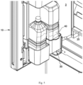
- FIG 2 is an enlarged view of the insulation door 10 including the dispenser 30.
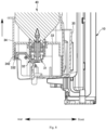
- FIGS. 3 and 4 are vertical sectional views of the dispenser 30 (sectional views along line A-A of FIG 2 ). Furthermore, the dispenser 30 shown in FIG 3 corresponds to the state where the flow path of the container connection assembly 31 described later is closed. In contrast, the dispenser 30 shown in FIG 4 corresponds to the state where the flow path of the container connection assembly 31 is open.
- the dispenser 30 of this embodiment includes a container connection assembly 31, a control lever 32, a first cover portion 33 for accommodating the container connection assembly 31 and the control lever 32, a second cover portion 34 for covering the first cover portion 33, and a housing portion 35 for accommodating the first cover portion 33 and the second cover portion 34.
- a beverage container 40 e.g., a plastic bottle
- the container connection assembly 31 of the dispenser 30 is installed in a downward position (with the drinking spout 41 facing the dispenser 30) to the container connection assembly 31 of the dispenser 30.
- the container connection assembly 31 includes a base 311, a container connection portion 312 connected to the drinking spout 41 of the beverage container 40, a fixed cylindrical portion 313 provided radially inward of the container connection portion 312, a movable cylindrical portion 314 provided radially inward of the fixed cylindrical portion 313, and a drinking water outlet portion 315 connected to the bottom ends of the fixed cylindrical portion 313 and the movable cylindrical portion 314. Additionally, a check valve 316 is connected in the movable cylindrical portion 314.
- the drinking water supplied from the beverage container 40 to the container connection assembly 31 is discharged to the outside from the drinking water outlet portion 315 after passing through the interior of the fixed cylindrical portion 313.
- the area inside the fixed cylindrical portion 313 included in the container connection assembly 31 of this embodiment corresponds to the drinking water flow path.
- control lever 32 includes a rotation shaft portion 321 for rotating the control lever 32 in the direction of arrow B, an operation portion 322 for performing the rotation operation of the control lever 32, and an outlet abutment portion 323 that abuts the drinking water outlet portion 315 due to the rotation of the control lever 32. Additionally, as shown in FIG 3 , the control lever 32 of this embodiment is installed in the designated position inside the first cover portion 33 in a manner that opposes the container connection assembly 31.
- the movable cylindrical portion 314 is configured to move vertically relative to the fixed cylindrical portion 313. As shown in FIG 3 , when the movable cylindrical portion 314 is in the initial position, the check valve 316 installed on the movable cylindrical portion 314 contacts the upper end of the fixed cylindrical portion 313. This closes the flow path of the container connection assembly 31, and the drinking water from the drinking spout 41 of the beverage container 40 facing the container connection portion 312 is blocked by the upper end of the fixed cylindrical portion 313.
- the check valve 316 rises in conjunction with the movement of the movable cylindrical portion 314, and the check valve 316 is separated from the fixed cylindrical portion 313. This opens the flow path of the container connection assembly 31, and the drinking water of the beverage container 40 flows into the fixed cylindrical portion 313.
- the control lever 32 preferably includes a drinking water receiving portion 324 for receiving the drinking water falling from the drinking water outlet portion 315.
- the drinking water receiving portion 324 of this embodiment has a bottom wall extending substantially horizontally from the front surface of the bottom of the operation portion 322 and a side wall standing up from the bottom wall. The falling drinking water is received in the area enclosed by the bottom wall and the side wall of the drinking water receiving portion 324.
- the drinking water receiving portion 324 Due to the provision of the drinking water receiving portion 324 with this shape, for example, water droplets (drinking water) attached to the drinking water outlet portion 315 will not fall into the refrigerating compartment 3. Furthermore, since the drinking water receiving portion 324 is located at the position of the operation portion 322 of the control lever 32, the drinking water receiving portion 324 rotates together with the rotation of the control lever 32 caused by user operation. Thus, during the user's water dispensing operation, the drinking water receiving portion 324 is not located in the water dispensing area directly below the drinking water outlet portion 315. In this way, even if the drinking water receiving portion 324 is provided separately, it will not obstruct the user's smooth water dispensing operation.
- FIGS. 5 and 6 the stopper device 36 for restricting the rotation of the control lever 32 when the insulation door 10 is closed to the refrigerating compartment 3 (storage compartment) will be described.
- FIG 5 is an enlarged perspective view of the refrigerator 1 when the insulation door 10 is in the open state.
- FIG 6 is an enlarged sectional view of the refrigerator 1 when the insulation door 10 is in the closed state (an enlarged vertical sectional view including the dispenser 30 and the stopper device 36).
- the stopper device 36 of this embodiment is provided on the side of the refrigerating compartment 3. Furthermore, the stopper device 36 extends substantially horizontally from a designated position of the refrigerating compartment 3 (e.g., the front end of a shelf opposite the dispenser 30, or a position such as the front wall of the fresh food compartment) to the inside of the first cover portion 33 of the dispenser 30. In this way, the stopper device 36 opposes the other end portion 325 of the control lever 32 (the end opposite to the operation portion 322) and restricts further rotation of the control lever 32.
- a designated position of the refrigerating compartment 3 e.g., the front end of a shelf opposite the dispenser 30, or a position such as the front wall of the fresh food compartment
- FIG. 7 is a vertical sectional view of the dispenser 30 with the second cover portion 34 in the reference position.
- FIG 8 is a vertical sectional view of the dispenser 30 with the second cover portion 34 in a position higher than the reference position.
- FIG 9 is a perspective view illustrating that the first cover portion 33 and the second cover portion 34 can be detached from the housing portion 35.
- the second cover portion 34 is mounted to the first cover portion 33 in a vertically movable manner. As shown in FIG 7 , when the second cover portion 34 is in a reference position, the upper wall 341 of the second cover portion 34 is located near the upper wall 331 of the first cover portion 33. When the first cover portion 33 and the second cover portion 34 are in such a positional relationship, the container connection assembly 31 with the beverage container 40 is placed on the first cover portion 33.
- the user can slide the second cover portion 34 to a position higher than the reference position.
- a protrusion 342 extending inward from the inner side wall of the second cover portion 34 is embedded into a recess 332 provided on the side wall of the first cover portion 33. In this way, the second cover portion 34 is locked in the elevated position.
- the second cover portion 34 when the container connection assembly 31 is placed on the first cover portion 33, the second cover portion 34 is in the reference position, and therefore the second cover portion 34 and the beverage container 40 do not interfere with each other. Furthermore, since the second cover portion 34 is in the reference position, the user can easily confirm the position of the container connection assembly 31. This allows for smooth placement of the container connection assembly 31 with the beverage container 40 on the first cover portion 33. Additionally, since the second cover portion 34 is in the lowered position (reference position), it can prevent misoperations such as accidentally rotating the control lever 32 during the operation.
- raising the second cover portion 34 increases the area of the beverage container 40 surrounded by the second cover portion 34, allowing the beverage container 40 placed on the dispenser 30 to maintain a prescribed posture.
- the first cover portion 33 and the second cover portion 34 can also be installed in a manner detachable from the housing portion 35.
- the housing portion 35 preferably includes a plate member 352 for blocking the opening area 351 formed when the first cover portion 33 and the second cover portion 34 are detached.
- the plate member 352 mounted to the housing portion 35 serves as part of the side wall of the housing portion 35.
- the opening area 351 formed after detaching the first cover portion 33 and the second cover portion 34 can be utilized as a storage space for stored items.
- the housing portion 35 is preferably installed in a manner detachable from the insulation door 10.
- the shape of the housing portion 35 is preferably similar to the shape of the storage shelf 20 provided on the inside of the insulation door 10.
- the area where the housing portion 35 is removed can be equipped with, for example, a storage shelf for storing items.
- the housing portion 35 (dispenser 30) can be detached from the insulation door 10 according to the user's intention, and the space after removing the housing portion 35 can be utilized as a storage space for stored items.
Landscapes
- Engineering & Computer Science (AREA)
- Mechanical Engineering (AREA)
- Chemical & Material Sciences (AREA)
- Combustion & Propulsion (AREA)
- Physics & Mathematics (AREA)
- Thermal Sciences (AREA)
- General Engineering & Computer Science (AREA)
- Devices For Dispensing Beverages (AREA)
- Refrigerator Housings (AREA)
- Devices That Are Associated With Refrigeration Equipment (AREA)
Abstract
Description
- The present application relates to a refrigerator.
- A refrigerator with a dispenser is provided, which stores drinking water in a water storage portion provided in the storage compartment and discharges the stored drinking water through user operation. For example, such a refrigerator with a dispenser is disclosed in
Patent Document 1.Patent Document 1 isJapanese Patent Application Publication No. 2016-114253 - In the refrigerator disclosed in
Patent Document 1, the drinking water outlet of the dispenser is provided on the surface side of the insulation door that opens and closes the storage compartment (the outside of the insulation door when the insulation door is closed). Thus, in the refrigerator ofPatent Document 1, the flow path from the water storage portion to the drinking water outlet is formed inside the insulation door, and the drinking water outlet is exposed to the outside from the surface side of the insulation door. Therefore, the storage compartment is communicated with the outside through the flow path and the drinking water outlet, leading to a decrease in the thermal insulation of the insulation door. - Furthermore, due to the reduced thermal insulation of the insulation door, it is necessary to lower the temperature of the cold air circulating inside the refrigerator. As a result, the refrigerator disclosed in
Patent Document 1 also has issues from the perspective of energy saving. Additionally, in the refrigerator disclosed inPatent Document 1, a structure for exposing the drinking water outlet to the outside needs to be separately provided. This increases the manufacturing cost compared to a refrigerator with a regular insulation door. - In view of these problems, an objective of the present application is to provide a refrigerator with a dispenser that does not reduce the thermal insulation of the insulation door and does not cause excessive cost increases.
- To solve the above problems, the refrigerator according to the present application comprises:
- a storage compartment;
- a insulation door provided at the front side of the storage compartment for opening and closing the storage compartment; and
- a dispenser provided on the inside of the insulation door and connected to a drinking spout of a beverage container for dispensing drinking water from the beverage container; wherein, when the insulation door is closed to the storage compartment, the dispenser is accommodated in the space formed by the insulation door and the storage compartment.
- Furthermore, in the refrigerator according to the present application, the dispenser includes:
- a container connection assembly connected to the beverage container and comprising a flow path for the drinking water of the beverage container; and
- a control lever rotatably supported at a designated position for controlling the opening and closing of the flow path of the container connection assembly.
- Furthermore, in the refrigerator according to the present application, the dispenser further comprises a stopper device that restricts the rotation of the control lever when the insulation door is closed to the storage compartment.
- Furthermore, in the refrigerator according to the present application, the container connection assembly further includes a drinking water outlet portion for discharging the drinking water when the flow path is flowing, and the control lever includes a drinking water receiving portion for receiving the drinking water falling from the drinking water outlet portion.
- Furthermore, in the refrigerator according to the present application, the dispenser further comprises:
- a first cover portion for accommodating the container connection assembly and the control lever; and
- a second cover portion for covering the first cover portion and mounted to the first cover portion in a vertically movable manner.
- Furthermore, in the refrigerator according to the present application, the dispenser further comprises a housing portion, and the first cover portion and the second cover portion are detachably mounted to the housing portion.
- Furthermore, in the refrigerator according to the present application, the dispenser is detachably mounted to the insulation door.
- Furthermore, in the refrigerator according to the present application, the container connection assembly includes a container connection portion connected to the drinking spout of the beverage container, a fixed cylindrical portion provided radially inward of the container connection portion, and a movable cylindrical portion provided radially inward of the fixed cylindrical portion, the drinking water outlet portion being connected to the bottom ends of the fixed cylindrical portion and the movable cylindrical portion, the drinking water supplied from the beverage container to the container connection assembly is discharged to the outside from the drinking water outlet portion after passing through the fixed cylindrical portion, the movable cylindrical portion being vertically movable relative to the fixed cylindrical portion, the movable cylindrical portion is provided with a check valve, and in the case where the movable cylindrical portion is in an initial position, the check valve provided on the movable cylindrical portion contacts the upper end of the fixed cylindrical portion to close the flow path of the container connection assembly; when the movable cylindrical portion rises, the check valve is separated from the fixed cylindrical portion, the flow path of the container connection assembly is opened, and the drinking water of the beverage container flows into the fixed cylindrical portion.
- Furthermore, in the refrigerator according to the present application, the control lever includes a rotation shaft portion, an operation portion for performing the rotation operation of the control lever, and an outlet abutment portion that abuts the drinking water outlet portion due to the rotation of the control lever, when the operation portion of the control lever is pushed to rotate the control lever, the outlet abutment portion of the control lever abuts the drinking water outlet portion of the container connection assembly, the movable cylindrical portion rises accordingly, the check valve rises in conjunction with the movement of the movable cylindrical portion, the check valve is separated from the fixed cylindrical portion, the flow path of the container connection assembly is opened, and the drinking water of the beverage container flows into the fixed cylindrical portion.
- Furthermore, in the refrigerator according to the present application, when the second cover portion is in the reference position, the upper wall of the second cover portion is located near the upper wall of the first cover portion, when the first cover portion and the second cover portion are in such a positional relationship, the container connection assembly with the beverage container is placed on the first cover portion, and after the container connection assembly is placed on the first cover portion, the second cover portion can be slid to a position higher than the reference position.
- The dispenser of the present application is accommodated in the space formed by the insulation door and the storage compartment when the insulation door is closed to the storage compartment. Thus, according to the present application, an area communicating with the outside of the refrigerator is not formed while the dispenser is provided. In this way, the thermal insulation of the insulation door is not reduced, and the cost does not increase excessively.
- Additionally, when the insulation door is closed to the storage compartment, the stopper device restricts the rotation of the control lever. Thus, according to the present application, it is possible to prevent the control lever of the dispenser from contacting a part provided on the storage compartment side and accidentally discharging drinking water from the dispenser during the process of closing the storage compartment with the insulation door.
- Furthermore, according to the present application, the control lever of the dispenser is provided with a drinking water receiving portion for receiving the drinking water falling from the drinking water outlet portion. Thus, for example, water droplets (drinking water) attached to the drinking water outlet portion will not fall into the storage compartment. Furthermore, when the user pushes a cup against the control lever to rotate the control lever, the drinking water receiving portion also rotates. In this way, during the user's water dispensing operation, the drinking water receiving portion is not located in the water dispensing area directly below the drinking water outlet portion. This ensures that the user's smooth water dispensing operation is not obstructed, even if the drinking water receiving portion is provided separately.
- Furthermore, the second cover portion of the dispenser is mounted to the first cover portion in a vertically movable manner. Thus, for example, when placing the beverage container on the dispenser, the second cover portion can be lowered to place the beverage container on the dispenser. This allows the action of placing the beverage container on the dispenser to be performed smoothly.
- Furthermore, according to the present application, the first cover portion and the second cover portion of the dispenser can be detached from the housing portion. Thus, the opening area formed after removing the first cover portion and the second cover portion of the housing portion can be utilized as a storage space for stored items.
- Furthermore, according to the present application, the dispenser (e.g., the housing portion) can be detached from the insulation door. In this way, when the dispenser is not used, the dispenser (housing portion) can be removed from the insulation door. Additionally, the area of the insulation door where the dispenser (housing portion) is removed can be equipped with, for example, a storage shelf for storing items. Thus, according to the present application, the dispenser can be detached from the insulation door according to the user's intention, and the space after removing the dispenser can be utilized as a storage space for stored items.
- The specific embodiments of the present application will be further described in detail below with reference to the drawings, in which:
-
FIG 1 is a perspective view of the refrigerator according to the present embodiment. -
FIG 2 is an enlarged view of the insulation door including the dispenser according to the present embodiment. -
FIG 3 is a vertical sectional view of the dispenser according to the present embodiment. -
FIG 4 is a vertical sectional view of the dispenser according to the present embodiment. -
FIG 5 is an enlarged perspective view of the refrigerator with the insulation door in the open state. -
FIG 6 is an enlarged sectional view of the refrigerator with the insulation door in the closed state. -
FIG 7 is a vertical sectional view of the dispenser with the second cover portion in a reference position according to the present embodiment. -
FIG 8 is a vertical sectional view of the dispenser with the second cover portion in a higher position according to the present embodiment. -
FIG 9 is a perspective view illustrating that the first cover portion and the second cover portion can be detached from the housing portion according to the present embodiment. - Next, referring to the drawings, the
refrigerator 1 according to an embodiment of the present application will be described in detail. Additionally, when describing therefrigerator 1 of this embodiment, the "up and down" direction corresponds to the height direction of therefrigerator 1, the "left and right" direction corresponds to the width direction of therefrigerator 1, and the "front and rear" direction corresponds to the anter-posterior depth direction of therefrigerator 1. Furthermore, the directions of the insulation door are defined based on the state where the insulation door closes the storage compartment. That is, the height direction (up and down direction) of the insulation door corresponds to the height direction of therefrigerator 1, the width direction (left and right direction) of the insulation door corresponds to the width direction of therefrigerator 1, and the anter-posterior depth direction (front and rear direction) of the insulation door corresponds to the anter-posterior depth direction of therefrigerator 1. - Referring to
FIG 1 , the overall structure of therefrigerator 1 according to this embodiment will be described. In this case,FIG 1 is a perspective view of therefrigerator 1. As shown inFIG 1 , therefrigerator 1 of this embodiment includes aninsulated cabinet 2 that corresponds to the main body of the refrigerator. Theinsulated cabinet 2 includes an outer housing made of steel plate, an inner housing made of synthetic resin, and an insulating material made of foamed polyurethane filled in the gap formed between the outer housing and the inner housing. - Inside the
insulated cabinet 2, there are insulated partition walls that divide multiple storage compartments, such as arefrigerating compartment 3 and a freezingcompartment 4. Therefrigerator 1 of this embodiment includes multiple storage compartments corresponding to therefrigerating compartment 3 and the freezingcompartment 4 above. However, the arrangement order of each storage compartment is not limited to this. Moreover, the number of storage compartments is not limited to this. - Additionally, each storage compartment of the
insulated cabinet 2 is provided with front surface openings, insulation doors are provided to open and close these openings. Theinsulation door 10, as shown inFIG 1 , is rotatably supported at the upper and lower ends of the left end, for example, when viewed from the front of therefrigerator 1, by ahinge member 5 on theinsulated cabinet 2, and closes the front surface opening of therefrigerating compartment 3. - The
insulation door 10 shown inFIG 1 includes a hollow box-shapedouter cover portion 11 that opens on the inside (back side); aninner panel part 12 mounted in the opening area on the inside of theouter cover part 11; and aframe 13 installed along the outer periphery of theinner panel part 12 for sealingly mounting theinner panel part 12 inside theouter cover part 11. Theinsulation door 10 is filled with an insulating material. - Additionally, there are elongated protruding
walls insulation door 10 is in the state of closing the refrigerating compartment 3) towards the inside of the refrigerating compartment 3 (the rear side of the insulation door 10). Astorage shelf 20 for storing items is supported on these protrudingwalls dispenser 30 is provided at the lowest portion on the inside of theinsulation door 10. - Thus, since the
dispenser 30 is provided on the inside of theinsulation door 10, when theinsulation door 10 closes therefrigerating compartment 3, thedispenser 30 is accommodated in the space (inside space of the refrigerator 1) formed by theinsulation door 10 and therefrigerating compartment 3. According to this embodiment, since thedispenser 30 is located in the inside space of therefrigerator 1, an area that communicates theinsulation door 10 with the outside of therefrigerator 1 is not formed while thedispenser 30 is provided. Therefore, the thermal insulation of theinsulation door 10 is not reduced, and the cost does not increase excessively. - Next, referring to
FIGS. 2 to 4 , thedispenser 30 of this embodiment will be described. In this case,FIG 2 is an enlarged view of theinsulation door 10 including thedispenser 30. Additionally,FIGS. 3 and4 are vertical sectional views of the dispenser 30 (sectional views along line A-A ofFIG 2 ). Furthermore, thedispenser 30 shown inFIG 3 corresponds to the state where the flow path of thecontainer connection assembly 31 described later is closed. In contrast, thedispenser 30 shown inFIG 4 corresponds to the state where the flow path of thecontainer connection assembly 31 is open. - As shown in
FIGS. 2 to 4 , thedispenser 30 of this embodiment includes acontainer connection assembly 31, acontrol lever 32, afirst cover portion 33 for accommodating thecontainer connection assembly 31 and thecontrol lever 32, asecond cover portion 34 for covering thefirst cover portion 33, and ahousing portion 35 for accommodating thefirst cover portion 33 and thesecond cover portion 34. As shown in the figures, a beverage container 40 (e.g., a plastic bottle) is installed in a downward position (with thedrinking spout 41 facing the dispenser 30) to thecontainer connection assembly 31 of thedispenser 30. - Furthermore, as shown in
FIG 3 , thecontainer connection assembly 31 includes abase 311, acontainer connection portion 312 connected to thedrinking spout 41 of thebeverage container 40, a fixedcylindrical portion 313 provided radially inward of thecontainer connection portion 312, a movablecylindrical portion 314 provided radially inward of the fixedcylindrical portion 313, and a drinkingwater outlet portion 315 connected to the bottom ends of the fixedcylindrical portion 313 and the movablecylindrical portion 314. Additionally, acheck valve 316 is connected in the movablecylindrical portion 314. - The drinking water supplied from the
beverage container 40 to thecontainer connection assembly 31 is discharged to the outside from the drinkingwater outlet portion 315 after passing through the interior of the fixedcylindrical portion 313. In other words, the area inside the fixedcylindrical portion 313 included in thecontainer connection assembly 31 of this embodiment corresponds to the drinking water flow path. - Next, the
control lever 32 includes arotation shaft portion 321 for rotating thecontrol lever 32 in the direction of arrow B, anoperation portion 322 for performing the rotation operation of thecontrol lever 32, and anoutlet abutment portion 323 that abuts the drinkingwater outlet portion 315 due to the rotation of thecontrol lever 32. Additionally, as shown inFIG 3 , thecontrol lever 32 of this embodiment is installed in the designated position inside thefirst cover portion 33 in a manner that opposes thecontainer connection assembly 31. - The movable
cylindrical portion 314 is configured to move vertically relative to the fixedcylindrical portion 313. As shown inFIG 3 , when the movablecylindrical portion 314 is in the initial position, thecheck valve 316 installed on the movablecylindrical portion 314 contacts the upper end of the fixedcylindrical portion 313. This closes the flow path of thecontainer connection assembly 31, and the drinking water from thedrinking spout 41 of thebeverage container 40 facing thecontainer connection portion 312 is blocked by the upper end of the fixedcylindrical portion 313. - In contrast, as shown in
FIG 4 , when, for example, a user pushes a cup against theoperation portion 322 of thecontrol lever 32 to rotate thecontrol lever 32 in the direction of arrow B, theoutlet abutment portion 323 of thecontrol lever 32 abuts the drinkingwater outlet portion 315 of thecontainer connection assembly 31. The movablecylindrical portion 314 then rises accordingly. - As a result, the
check valve 316 rises in conjunction with the movement of the movablecylindrical portion 314, and thecheck valve 316 is separated from the fixedcylindrical portion 313. This opens the flow path of thecontainer connection assembly 31, and the drinking water of thebeverage container 40 flows into the fixedcylindrical portion 313. - Furthermore, as shown in
FIGS. 3 and4 , thecontrol lever 32 preferably includes a drinkingwater receiving portion 324 for receiving the drinking water falling from the drinkingwater outlet portion 315. The drinkingwater receiving portion 324 of this embodiment has a bottom wall extending substantially horizontally from the front surface of the bottom of theoperation portion 322 and a side wall standing up from the bottom wall. The falling drinking water is received in the area enclosed by the bottom wall and the side wall of the drinkingwater receiving portion 324. - Due to the provision of the drinking
water receiving portion 324 with this shape, for example, water droplets (drinking water) attached to the drinkingwater outlet portion 315 will not fall into therefrigerating compartment 3. Furthermore, since the drinkingwater receiving portion 324 is located at the position of theoperation portion 322 of thecontrol lever 32, the drinkingwater receiving portion 324 rotates together with the rotation of thecontrol lever 32 caused by user operation. Thus, during the user's water dispensing operation, the drinkingwater receiving portion 324 is not located in the water dispensing area directly below the drinkingwater outlet portion 315. In this way, even if the drinkingwater receiving portion 324 is provided separately, it will not obstruct the user's smooth water dispensing operation. - Next, referring to
FIGS. 5 and6 , thestopper device 36 for restricting the rotation of thecontrol lever 32 when theinsulation door 10 is closed to the refrigerating compartment 3 (storage compartment) will be described. In this case,FIG 5 is an enlarged perspective view of therefrigerator 1 when theinsulation door 10 is in the open state. Additionally,FIG 6 is an enlarged sectional view of therefrigerator 1 when theinsulation door 10 is in the closed state (an enlarged vertical sectional view including thedispenser 30 and the stopper device 36). - As shown in
FIGS. 5 and6 , thestopper device 36 of this embodiment is provided on the side of therefrigerating compartment 3. Furthermore, thestopper device 36 extends substantially horizontally from a designated position of the refrigerating compartment 3 (e.g., the front end of a shelf opposite thedispenser 30, or a position such as the front wall of the fresh food compartment) to the inside of thefirst cover portion 33 of thedispenser 30. In this way, thestopper device 36 opposes theother end portion 325 of the control lever 32 (the end opposite to the operation portion 322) and restricts further rotation of thecontrol lever 32. - Due to the provision of such a
stopper device 36, it is possible to prevent thecontrol lever 32 of thedispenser 30 from contacting a designated position of the refrigerating compartment 3 (e.g., a portion of therefrigerating compartment 3 opposite the dispenser 30) and accidentally rotating during the process of closing therefrigerating compartment 3 with theinsulation door 10. In this way, it is possible to prevent drinking water from being accidentally discharged from thedispenser 30. - Next, referring to
FIGS. 7 and9 , thefirst cover portion 33 and thesecond cover portion 34 of thedispenser 30 will be described in detail. In this case,FIG 7 is a vertical sectional view of thedispenser 30 with thesecond cover portion 34 in the reference position. Additionally,FIG 8 is a vertical sectional view of thedispenser 30 with thesecond cover portion 34 in a position higher than the reference position. Furthermore,FIG 9 is a perspective view illustrating that thefirst cover portion 33 and thesecond cover portion 34 can be detached from thehousing portion 35. - The
second cover portion 34 is mounted to thefirst cover portion 33 in a vertically movable manner. As shown inFIG 7 , when thesecond cover portion 34 is in a reference position, theupper wall 341 of thesecond cover portion 34 is located near theupper wall 331 of thefirst cover portion 33. When thefirst cover portion 33 and thesecond cover portion 34 are in such a positional relationship, thecontainer connection assembly 31 with thebeverage container 40 is placed on thefirst cover portion 33. - Additionally, as shown in
FIG 8 , after thecontainer connection assembly 31 is placed on thefirst cover portion 33, the user can slide thesecond cover portion 34 to a position higher than the reference position. At this time, aprotrusion 342 extending inward from the inner side wall of thesecond cover portion 34 is embedded into arecess 332 provided on the side wall of thefirst cover portion 33. In this way, thesecond cover portion 34 is locked in the elevated position. - Thus, when the
container connection assembly 31 is placed on thefirst cover portion 33, thesecond cover portion 34 is in the reference position, and therefore thesecond cover portion 34 and thebeverage container 40 do not interfere with each other. Furthermore, since thesecond cover portion 34 is in the reference position, the user can easily confirm the position of thecontainer connection assembly 31. This allows for smooth placement of thecontainer connection assembly 31 with thebeverage container 40 on thefirst cover portion 33. Additionally, since thesecond cover portion 34 is in the lowered position (reference position), it can prevent misoperations such as accidentally rotating thecontrol lever 32 during the operation. - Furthermore, after placing the
container connection assembly 31 on thefirst cover portion 33, raising thesecond cover portion 34 increases the area of thebeverage container 40 surrounded by thesecond cover portion 34, allowing thebeverage container 40 placed on thedispenser 30 to maintain a prescribed posture. - Furthermore, as shown in
FIG 9 , thefirst cover portion 33 and thesecond cover portion 34 can also be installed in a manner detachable from thehousing portion 35. In this case, thehousing portion 35 preferably includes aplate member 352 for blocking theopening area 351 formed when thefirst cover portion 33 and thesecond cover portion 34 are detached. Theplate member 352 mounted to thehousing portion 35 serves as part of the side wall of thehousing portion 35. - According to the
housing portion 35 with such a configuration, theopening area 351 formed after detaching thefirst cover portion 33 and thesecond cover portion 34 can be utilized as a storage space for stored items. - Additionally, the
housing portion 35 is preferably installed in a manner detachable from theinsulation door 10. In this case, the shape of thehousing portion 35 is preferably similar to the shape of thestorage shelf 20 provided on the inside of theinsulation door 10. - According to the
housing portion 35 with such a shape, the area where thehousing portion 35 is removed can be equipped with, for example, a storage shelf for storing items. Thus, the housing portion 35 (dispenser 30) can be detached from theinsulation door 10 according to the user's intention, and the space after removing thehousing portion 35 can be utilized as a storage space for stored items. - The above detailed description explains the embodiments of the present application. However, the foregoing description is intended to facilitate understanding of the present application and is not intended to limit the essence of the present application. The present application can encompass modifications or improvements without departing from its essence. Additionally, the present application includes equivalents thereof.
Claims (10)
- A refrigerator, comprising:a storage compartment;a insulation door provided at the front side of the storage compartment for opening and closing the storage compartment; anda dispenser provided on the inside of the insulation door and connected to a drinking spout of a beverage container for dispensing drinking water from the beverage container; wherein, when the insulation door is closed to the storage compartment, the dispenser is accommodated in the space formed by the insulation door and the storage compartment.
- The refrigerator according to claim 1, wherein the dispenser comprises:a container connection assembly connected to the beverage container and comprising a flow path for the drinking water of the beverage container; anda control lever rotatably supported at a designated position for controlling the opening and closing of the flow path of the container connection assembly.
- The refrigerator according to claim 2, wherein the dispenser further comprises a stopper device that restricts the rotation of the control lever when the insulation door is closed to the storage compartment.
- The refrigerator according to claim 2, wherein the container connection assembly further comprises a drinking water outlet portion for discharging the drinking water when the flow path is flowing, and the control lever includes a drinking water receiving portion for receiving the drinking water falling from the drinking water outlet portion.
- The refrigerator according to claim 2, wherein the dispenser further comprises:a first cover portion for accommodating the container connection assembly and the control lever; anda second cover portion for covering the first cover portion and mounted to the first cover portion in a vertically movable manner.
- The refrigerator according to claim 3, wherein the dispenser further comprises a housing portion, and the first cover portion and the second cover portion are detachably mounted to the housing portion.
- The refrigerator according to claim 1, wherein the dispenser is detachably mounted to the insulation door.
- The refrigerator according to claim 4, wherein the container connection assembly comprises a container connection portion connected to the drinking spout of the beverage container, a fixed cylindrical portion provided radially inward of the container connection portion, and a movable cylindrical portion provided radially inward of the fixed cylindrical portion, the drinking water outlet portion being connected to the bottom ends of the fixed cylindrical portion and the movable cylindrical portion, the drinking water supplied from the beverage container to the container connection assembly is discharged to the outside from the drinking water outlet portion after passing through the fixed cylindrical portion, the movable cylindrical portion being vertically movable relative to the fixed cylindrical portion, the movable cylindrical portion is provided with a check valve, and in the case where the movable cylindrical portion is in an initial position, the check valve provided on the movable cylindrical portion contacts the upper end of the fixed cylindrical portion to close the flow path of the container connection assembly; when the movable cylindrical portion rises, the check valve is separated from the fixed cylindrical portion, the flow path of the container connection assembly is opened, and the drinking water of the beverage container flows into the fixed cylindrical portion.
- The refrigerator according to claim 8, wherein the control lever comprises a rotation shaft portion, an operation portion for performing the rotation operation of the control lever, and an outlet abutment portion that abuts the drinking water outlet portion due to the rotation of the control lever, when the operation portion of the control lever is pushed to rotate the control lever, the outlet abutment portion of the control lever abuts the drinking water outlet portion of the container connection assembly, the movable cylindrical portion rises accordingly, the check valve rises in conjunction with the movement of the movable cylindrical portion, the check valve is separated from the fixed cylindrical portion, the flow path of the container connection assembly is opened, and the drinking water of the beverage container flows into the fixed cylindrical portion.
- The refrigerator according to claim 5, wherein, in the case where the second cover portion is in a reference position, the upper wall of the second cover portion is located near the upper wall of the first cover portion, when the first cover portion and the second cover portion are in such a positional relationship, the container connection assembly with the beverage container is placed on the first cover portion, and after the container connection assembly is placed on the first cover portion, the second cover portion can be slid to a position higher than the reference position.
Applications Claiming Priority (2)
| Application Number | Priority Date | Filing Date | Title |
|---|---|---|---|
| JP2021210832A JP2023095128A (en) | 2021-12-24 | 2021-12-24 | refrigerator |
| PCT/CN2022/141516 WO2023116898A1 (en) | 2021-12-24 | 2022-12-23 | Refrigerator |
Publications (2)
| Publication Number | Publication Date |
|---|---|
| EP4455585A1 true EP4455585A1 (en) | 2024-10-30 |
| EP4455585A4 EP4455585A4 (en) | 2025-03-26 |
Family
ID=86901368
Family Applications (1)
| Application Number | Title | Priority Date | Filing Date |
|---|---|---|---|
| EP22910208.2A Pending EP4455585A4 (en) | 2021-12-24 | 2022-12-23 | FRIDGE |
Country Status (4)
| Country | Link |
|---|---|
| EP (1) | EP4455585A4 (en) |
| JP (1) | JP2023095128A (en) |
| CN (1) | CN118451289A (en) |
| WO (1) | WO2023116898A1 (en) |
Family Cites Families (9)
| Publication number | Priority date | Publication date | Assignee | Title |
|---|---|---|---|---|
| JP3020845B2 (en) * | 1995-09-14 | 2000-03-15 | 株式会社東芝 | Cooled beverage supply device |
| KR980003416A (en) * | 1996-06-29 | 1998-03-30 | 배순훈 | Refrigerator water supply unit |
| JPH11142052A (en) * | 1997-11-06 | 1999-05-28 | Fujitsu General Ltd | Electric refrigerator |
| MX2011008118A (en) * | 2009-02-02 | 2011-08-17 | Lg Electronics Inc | Refrigerator. |
| JP6333163B2 (en) | 2014-12-10 | 2018-05-30 | 日立アプライアンス株式会社 | refrigerator |
| CN105783403B (en) * | 2016-03-14 | 2019-02-15 | 合肥华凌股份有限公司 | Refrigerator |
| KR101997259B1 (en) * | 2017-05-26 | 2019-10-01 | 엘지전자 주식회사 | Refrigerator |
| US11112159B2 (en) * | 2018-08-01 | 2021-09-07 | Lg Electronics Inc. | Refrigerator |
| JP7455370B2 (en) * | 2020-04-02 | 2024-03-26 | アクア株式会社 | Container connection module and refrigerator with it |
-
2021
- 2021-12-24 JP JP2021210832A patent/JP2023095128A/en active Pending
-
2022
- 2022-12-23 WO PCT/CN2022/141516 patent/WO2023116898A1/en not_active Ceased
- 2022-12-23 EP EP22910208.2A patent/EP4455585A4/en active Pending
- 2022-12-23 CN CN202280085745.5A patent/CN118451289A/en active Pending
Also Published As
| Publication number | Publication date |
|---|---|
| WO2023116898A8 (en) | 2024-06-27 |
| WO2023116898A1 (en) | 2023-06-29 |
| EP4455585A4 (en) | 2025-03-26 |
| JP2023095128A (en) | 2023-07-06 |
| CN118451289A (en) | 2024-08-06 |
Similar Documents
| Publication | Publication Date | Title |
|---|---|---|
| KR100488074B1 (en) | Door structure of refrigerator | |
| US10119747B2 (en) | Refrigerator including a door having a storage chamber | |
| US8418497B2 (en) | Refrigerator | |
| US20080041089A1 (en) | Ice tray assembly and refrigerator having same | |
| US20080307823A1 (en) | Refrigerator | |
| US20170167780A1 (en) | Refrigerator | |
| US20110283734A1 (en) | Refrigerator | |
| KR101713227B1 (en) | refrigerator | |
| CN116057340A (en) | refrigerator | |
| EP3611453B1 (en) | Refrigerator | |
| KR20210156195A (en) | Refrigerator | |
| EP2245400B1 (en) | Refrigerator with a door hinge assembly | |
| KR20240107070A (en) | ice maker and refrigerator having the same | |
| EP0146180B1 (en) | Refrigerator door with drink dispenser | |
| AU2007285171B2 (en) | Ice tray assembly and refrigerator having same | |
| CN118451289A (en) | Refrigerator with a refrigerator body | |
| KR20200139043A (en) | Ice maker and refrigerator having the same | |
| KR20080106722A (en) | Rice refrigerator | |
| US20220003480A1 (en) | Ice maker and refrigerator having the same | |
| KR20080106720A (en) | Rice refrigerator | |
| US20260126242A1 (en) | Refrigerator | |
| EP4603773A1 (en) | Refrigerator | |
| US11885558B2 (en) | Sealing assembly for refrigerator | |
| KR20240149257A (en) | Refrigerator | |
| KR20250069159A (en) | Refrigerator |
Legal Events
| Date | Code | Title | Description |
|---|---|---|---|
| STAA | Information on the status of an ep patent application or granted ep patent |
Free format text: STATUS: THE INTERNATIONAL PUBLICATION HAS BEEN MADE |
|
| PUAI | Public reference made under article 153(3) epc to a published international application that has entered the european phase |
Free format text: ORIGINAL CODE: 0009012 |
|
| STAA | Information on the status of an ep patent application or granted ep patent |
Free format text: STATUS: REQUEST FOR EXAMINATION WAS MADE |
|
| 17P | Request for examination filed |
Effective date: 20240620 |
|
| AK | Designated contracting states |
Kind code of ref document: A1 Designated state(s): AL AT BE BG CH CY CZ DE DK EE ES FI FR GB GR HR HU IE IS IT LI LT LU LV MC ME MK MT NL NO PL PT RO RS SE SI SK SM TR |
|
| REG | Reference to a national code |
Ref country code: DE Ref legal event code: R079 Free format text: PREVIOUS MAIN CLASS: F25D0011020000 Ipc: F25D0023120000 |
|
| A4 | Supplementary search report drawn up and despatched |
Effective date: 20250224 |
|
| RIC1 | Information provided on ipc code assigned before grant |
Ipc: B67D 3/04 20060101ALI20250218BHEP Ipc: B67D 3/02 20060101ALI20250218BHEP Ipc: B67D 3/00 20060101ALI20250218BHEP Ipc: F25D 23/04 20060101ALI20250218BHEP Ipc: F25D 23/12 20060101AFI20250218BHEP |
|
| DAV | Request for validation of the european patent (deleted) | ||
| DAX | Request for extension of the european patent (deleted) |