EP4455578A1 - Air-conditioning device - Google Patents
Air-conditioning device Download PDFInfo
- Publication number
- EP4455578A1 EP4455578A1 EP21968784.5A EP21968784A EP4455578A1 EP 4455578 A1 EP4455578 A1 EP 4455578A1 EP 21968784 A EP21968784 A EP 21968784A EP 4455578 A1 EP4455578 A1 EP 4455578A1
- Authority
- EP
- European Patent Office
- Prior art keywords
- unit
- refrigerant
- indoor
- valve
- outdoor
- Prior art date
- Legal status (The legal status is an assumption and is not a legal conclusion. Google has not performed a legal analysis and makes no representation as to the accuracy of the status listed.)
- Withdrawn
Links
Images



Classifications
-
- F—MECHANICAL ENGINEERING; LIGHTING; HEATING; WEAPONS; BLASTING
- F24—HEATING; RANGES; VENTILATING
- F24F—AIR-CONDITIONING; AIR-HUMIDIFICATION; VENTILATION; USE OF AIR CURRENTS FOR SCREENING
- F24F11/00—Control or safety arrangements
- F24F11/30—Control or safety arrangements for purposes related to the operation of the system, e.g. for safety or monitoring
- F24F11/32—Responding to malfunctions or emergencies
- F24F11/36—Responding to malfunctions or emergencies to leakage of heat-exchange fluid
-
- F—MECHANICAL ENGINEERING; LIGHTING; HEATING; WEAPONS; BLASTING
- F24—HEATING; RANGES; VENTILATING
- F24F—AIR-CONDITIONING; AIR-HUMIDIFICATION; VENTILATION; USE OF AIR CURRENTS FOR SCREENING
- F24F1/00—Room units for air-conditioning, e.g. separate or self-contained units or units receiving primary air from a central station
- F24F1/06—Separate outdoor units, e.g. outdoor unit to be linked to a separate room comprising a compressor and a heat exchanger
- F24F1/26—Refrigerant piping
- F24F1/32—Refrigerant piping for connecting the separate outdoor units to indoor units
-
- F—MECHANICAL ENGINEERING; LIGHTING; HEATING; WEAPONS; BLASTING
- F25—REFRIGERATION OR COOLING; COMBINED HEATING AND REFRIGERATION SYSTEMS; HEAT PUMP SYSTEMS; MANUFACTURE OR STORAGE OF ICE; LIQUEFACTION SOLIDIFICATION OF GASES
- F25B—REFRIGERATION MACHINES, PLANTS OR SYSTEMS; COMBINED HEATING AND REFRIGERATION SYSTEMS; HEAT PUMP SYSTEMS
- F25B13/00—Compression machines, plants or systems, with reversible cycle
-
- F—MECHANICAL ENGINEERING; LIGHTING; HEATING; WEAPONS; BLASTING
- F25—REFRIGERATION OR COOLING; COMBINED HEATING AND REFRIGERATION SYSTEMS; HEAT PUMP SYSTEMS; MANUFACTURE OR STORAGE OF ICE; LIQUEFACTION SOLIDIFICATION OF GASES
- F25B—REFRIGERATION MACHINES, PLANTS OR SYSTEMS; COMBINED HEATING AND REFRIGERATION SYSTEMS; HEAT PUMP SYSTEMS
- F25B41/00—Fluid-circulation arrangements
- F25B41/20—Disposition of valves, e.g. of on-off valves or flow control valves
-
- F—MECHANICAL ENGINEERING; LIGHTING; HEATING; WEAPONS; BLASTING
- F25—REFRIGERATION OR COOLING; COMBINED HEATING AND REFRIGERATION SYSTEMS; HEAT PUMP SYSTEMS; MANUFACTURE OR STORAGE OF ICE; LIQUEFACTION SOLIDIFICATION OF GASES
- F25B—REFRIGERATION MACHINES, PLANTS OR SYSTEMS; COMBINED HEATING AND REFRIGERATION SYSTEMS; HEAT PUMP SYSTEMS
- F25B41/00—Fluid-circulation arrangements
- F25B41/20—Disposition of valves, e.g. of on-off valves or flow control valves
- F25B41/24—Arrangement of shut-off valves for disconnecting a part of the refrigerant cycle, e.g. an outdoor part
-
- F—MECHANICAL ENGINEERING; LIGHTING; HEATING; WEAPONS; BLASTING
- F25—REFRIGERATION OR COOLING; COMBINED HEATING AND REFRIGERATION SYSTEMS; HEAT PUMP SYSTEMS; MANUFACTURE OR STORAGE OF ICE; LIQUEFACTION SOLIDIFICATION OF GASES
- F25B—REFRIGERATION MACHINES, PLANTS OR SYSTEMS; COMBINED HEATING AND REFRIGERATION SYSTEMS; HEAT PUMP SYSTEMS
- F25B49/00—Arrangement or mounting of control or safety devices
- F25B49/005—Arrangement or mounting of control or safety devices of safety devices
-
- F—MECHANICAL ENGINEERING; LIGHTING; HEATING; WEAPONS; BLASTING
- F25—REFRIGERATION OR COOLING; COMBINED HEATING AND REFRIGERATION SYSTEMS; HEAT PUMP SYSTEMS; MANUFACTURE OR STORAGE OF ICE; LIQUEFACTION SOLIDIFICATION OF GASES
- F25B—REFRIGERATION MACHINES, PLANTS OR SYSTEMS; COMBINED HEATING AND REFRIGERATION SYSTEMS; HEAT PUMP SYSTEMS
- F25B49/00—Arrangement or mounting of control or safety devices
- F25B49/02—Arrangement or mounting of control or safety devices for compression type machines, plants or systems
-
- F—MECHANICAL ENGINEERING; LIGHTING; HEATING; WEAPONS; BLASTING
- F25—REFRIGERATION OR COOLING; COMBINED HEATING AND REFRIGERATION SYSTEMS; HEAT PUMP SYSTEMS; MANUFACTURE OR STORAGE OF ICE; LIQUEFACTION SOLIDIFICATION OF GASES
- F25B—REFRIGERATION MACHINES, PLANTS OR SYSTEMS; COMBINED HEATING AND REFRIGERATION SYSTEMS; HEAT PUMP SYSTEMS
- F25B2313/00—Compression machines, plants or systems with reversible cycle not otherwise provided for
- F25B2313/023—Compression machines, plants or systems with reversible cycle not otherwise provided for using multiple indoor units
- F25B2313/0233—Compression machines, plants or systems with reversible cycle not otherwise provided for using multiple indoor units in parallel arrangements
-
- F—MECHANICAL ENGINEERING; LIGHTING; HEATING; WEAPONS; BLASTING
- F25—REFRIGERATION OR COOLING; COMBINED HEATING AND REFRIGERATION SYSTEMS; HEAT PUMP SYSTEMS; MANUFACTURE OR STORAGE OF ICE; LIQUEFACTION SOLIDIFICATION OF GASES
- F25B—REFRIGERATION MACHINES, PLANTS OR SYSTEMS; COMBINED HEATING AND REFRIGERATION SYSTEMS; HEAT PUMP SYSTEMS
- F25B2500/00—Problems to be solved
- F25B2500/22—Preventing, detecting or repairing leaks of refrigeration fluids
- F25B2500/221—Preventing leaks from developing
-
- F—MECHANICAL ENGINEERING; LIGHTING; HEATING; WEAPONS; BLASTING
- F25—REFRIGERATION OR COOLING; COMBINED HEATING AND REFRIGERATION SYSTEMS; HEAT PUMP SYSTEMS; MANUFACTURE OR STORAGE OF ICE; LIQUEFACTION SOLIDIFICATION OF GASES
- F25B—REFRIGERATION MACHINES, PLANTS OR SYSTEMS; COMBINED HEATING AND REFRIGERATION SYSTEMS; HEAT PUMP SYSTEMS
- F25B2500/00—Problems to be solved
- F25B2500/22—Preventing, detecting or repairing leaks of refrigeration fluids
- F25B2500/222—Detecting refrigerant leaks
-
- F—MECHANICAL ENGINEERING; LIGHTING; HEATING; WEAPONS; BLASTING
- F25—REFRIGERATION OR COOLING; COMBINED HEATING AND REFRIGERATION SYSTEMS; HEAT PUMP SYSTEMS; MANUFACTURE OR STORAGE OF ICE; LIQUEFACTION SOLIDIFICATION OF GASES
- F25B—REFRIGERATION MACHINES, PLANTS OR SYSTEMS; COMBINED HEATING AND REFRIGERATION SYSTEMS; HEAT PUMP SYSTEMS
- F25B2600/00—Control issues
- F25B2600/25—Control of valves
-
- F—MECHANICAL ENGINEERING; LIGHTING; HEATING; WEAPONS; BLASTING
- F25—REFRIGERATION OR COOLING; COMBINED HEATING AND REFRIGERATION SYSTEMS; HEAT PUMP SYSTEMS; MANUFACTURE OR STORAGE OF ICE; LIQUEFACTION SOLIDIFICATION OF GASES
- F25B—REFRIGERATION MACHINES, PLANTS OR SYSTEMS; COMBINED HEATING AND REFRIGERATION SYSTEMS; HEAT PUMP SYSTEMS
- F25B2600/00—Control issues
- F25B2600/25—Control of valves
- F25B2600/2519—On-off valves
-
- F—MECHANICAL ENGINEERING; LIGHTING; HEATING; WEAPONS; BLASTING
- F25—REFRIGERATION OR COOLING; COMBINED HEATING AND REFRIGERATION SYSTEMS; HEAT PUMP SYSTEMS; MANUFACTURE OR STORAGE OF ICE; LIQUEFACTION SOLIDIFICATION OF GASES
- F25B—REFRIGERATION MACHINES, PLANTS OR SYSTEMS; COMBINED HEATING AND REFRIGERATION SYSTEMS; HEAT PUMP SYSTEMS
- F25B2700/00—Sensing or detecting of parameters; Sensors therefor
- F25B2700/19—Pressures
Definitions
- the present disclosure relates to an air-conditioning apparatus including a shut-off valve.
- Patent Literature 1 discloses an air-conditioning apparatus that closes, when detecting a leak of refrigerant, a solenoid valve and a shut-off valve in order to reduce further occurrence of the refrigerant leak.
- the air-conditioning apparatus according to Patent Literature 1 includes an electromagnetic expansion valve and a shut-off valve that are provided in the following manner.
- the electromagnetic expansion valve is provided in a refrigerant circuit that is located between an outdoor heat exchanger and an indoor heat exchanger such that no compressor is interposed between the outdoor heat exchanger and the indoor heat exchanger.
- the shut-off valve is provided in a refrigerant circuit that is located between an outdoor heat exchanger and an indoor heat exchanger, with a compressor interposed between the outdoor heat exchanger and the indoor heat exchanger.
- Patent Literature 1 proposes use of a controller that closes the electromagnetic expansion valve to cause refrigerant to collect on an outdoor heat exchanger side, when a leak of refrigerant is detected, and then closes the shut-off valve.
- Patent Literature 1 Japanese Unexamined Patent Application Publication No. 2000-97527
- refrigerant leaks from an air-conditioning apparatus further occurrence of such a refrigerant leak is reduced using, for example, the controller described in Patent Literature 1, the air-conditioning apparatus is stopped, and a component of the air-conditioning apparatus is then repaired or replaced by a new one. In this case, it is necessary to find a location at which the refrigerant leak occurs. Furthermore, in the case of repairing or replacing a component of the air-conditioning apparatus, in some cases, the refrigerant is drawn out from the air-conditioning apparatus, the component is repaired or replaced by a new one, and refrigerant is then re-filled into the air-conditioning apparatus.
- refrigerant pipes have no part that allows connection of external equipment such as, a temperature sensor, a pressure sensor, a pump for drawing the refrigerant, a pump for re-filing refrigerant, and a vacuum pump. Inevitably, it takes time to, for example, find a location where a refrigerant leak occur, draw out refrigerant, and re-fill refrigerant.
- the present disclosure is applied in view of the above circumstances, and relates to an air-conditioning apparatus that is improved in maintainability.
- An air-conditioning apparatus includes: an outdoor unit including a compressor and an outdoor heat exchanger, and configured to generate cooling energy or heating energy; an indoor unit including an indoor heat exchanger, and configured to perform an air-conditioning operation with the cooling energy or the heating energy that is generated by the outdoor unit; a refrigerant pipe provided between the outdoor unit and the indoor unit, and forming a refrigerant circuit in which refrigerant circulates; and a shut-off valve provided at the refrigerant pipe, and configured to be closed when a refrigerant leak is detected.
- the shut-off valve includes a service port communicating with the refrigerant pipe.
- the air-conditioning apparatus includes a shut-off valve having a service port communicating with a refrigerant pipe. It is therefore possible to connect external equipment with the refrigerant pipe by attaching the external equipment to the service port. Thus, maintenance can be performed on the air-conditioning apparatus, with the external equipment attached to the service port, whereby the maintainability of the air-conditioning apparatus can be improved.
- Air-conditioning apparatuses will be described below with reference to the drawings. Descriptions of the present disclosure that concern the embodiments described below are not limiting but various modifications can be made without departing from the scope and spirit of the present disclosure. The present disclosure may encompass all possible combinations of configurations as described below regarding the embodiments.
- the drawings illustrate examples of configurations of the air-conditioning apparatuses, and do not limit the configurations described in the present disclosure. Although directional terms (for example, "upper” and “lower”) are used as appropriate in order that the embodiments be more easily understood, they are not limiting.
- components that are the same as or equivalent to those in a previous figure or previous figures are denoted by the same reference signs. The same is true of the entire text of the specification. In each of the figures, relative dimensions, shapes, or other features of components may differ from actual ones.
- Fig. 1 is a schematic view illustrating an example of a circuit configuration of an air-conditioning apparatus 100 according to Embodiment 1.
- the air-conditioning apparatus 100 as illustrated in Fig. 1 includes an outdoor unit 3, plural indoor units 2a, 2b, and 2c, and a refrigerant flow switching device 9, and is capable of switching its operation between a cooling operation and a heating operation.
- the air-conditioning apparatus 100 as illustrated in Fig. 1 includes the indoor units 2a, 2b, and 2c
- the air-conditioning apparatus 100 may include a single indoor unit.
- the air-conditioning apparatus 100 may be configured to perform only the cooling operation or only the heating operation. In this case, the air-conditioning apparatus 100 does not include the refrigerant flow switching device 9 as illustrated in Fig. 1 .
- the air-conditioning apparatus 100 includes the outdoor unit 3 serving as a heat source unit; the indoor units 2a, 2b, and 2c; and plural shut-off valves 30 provided between the outdoor unit 3 and the indoor units 2a, 2b, and 2c.
- the shut-off valve 30 includes an indoor-unit-side shut-off valve 30a provided close to the indoor units 2, and an outdoor-unit-side shut-off valve 30b provided close to the outdoor unit 3.
- the outdoor unit 3, the outdoor-unit-side shut-off valve 30b, the indoor-unit-side shut-off valve 30a, and each of the indoor units 2a, 2b, and 2c are connected by refrigerant pipes 10.
- a refrigerant circuit is formed in which refrigerant circulates through the refrigerant pipes 10.
- solid arrows each indicate the flow of the refrigerant in the cooling operation
- dashed arrows each indicate the flow of the refrigerant in the heating operation.
- a side toward which the refrigerant moves along the flow direction is referred to as a downstream side. That is, the refrigerant flows from an upstream side toward the downstream side.
- the refrigerant to be used can be considered to be R32 refrigerant, but is not limited to the R32 refrigerant. The flow of the refrigerant in the cooling operation and that in the heating operation will be described later.
- shut-off valve 30 the indoor-unit-side shut-off valve 30a and the outdoor-unit-side shut-off valve 30b are each simply referred to as “shut-off valve 30" as appropriate in the case where they do not particularly need to be distinguished from each other.
- shut-off valve 30 is applicable to both a single shut-off valve 30 and plural shut-off valves 30.
- the air-conditioning apparatus 100 includes indoor-unit-side shut-off valves 30a that are provided at respective refrigerant pipes 10, that is, the refrigerant pipe 10 connected to the indoor unit 2a, the refrigerant pipe 10 connected to the indoor unit 2b, and the refrigerant pipe 10 connected to the indoor unit 2c.
- indoor-unit-side shut-off valves 30a-1 and 30a-2 are associated with the indoor unit 2a; the indoor-unit-side shut-off valves 30a-3 and 30a-4 are associated with the indoor unit 2b; and the indoor-unit-side shut-off valves 30a-5 and 30a-6 are associated with the indoor unit 2c.
- the indoor-unit-side shut-off valves 30a-1 to 30a-6 are each simply referred to as "indoor-unit-side shut-off valve 30a" as appropriate in the case where they do not particularly need to be distinguished from each other.
- the following description is also made assuming that the term "indoor-unit-side shut-off valve 30a" is applicable to both a single indoor-unit-side shut-off valve 30a and plural indoor-unit-side shut-off valves 30a.
- the air-conditioning apparatus 100 includes outdoor-unit-side shut-off valves 30b provided at respective refrigerant pipes 10 connected to the outdoor unit 3.
- outdoor-unit-side shut-off valves 30b-1 and 30b-2 are provided at respective refrigerant pipes 10 connected to the outdoor unit 3.
- the outdoor-unit-side shut-off valve 30b-1 and the outdoor-unit-side shut-off valve 30b-2 are each simply referred to as "outdoor-unit-side shut-off valve 30b" as appropriate in the case where they do not particularly need to be distinguished from each other.
- the following description is also made assuming that the term "outdoor-unit-side shut-off valve 30b" is applicable to both a single outdoor-unit-side shut-off valve 30b and plural outdoor-unit-side shut-off valves 30b.
- the outdoor unit 3 includes a compressor 6, an outdoor heat exchanger 7, an expansion valve 8, the refrigerant flow switching device 9, and an accumulator 25.
- the compressor 6 compresses refrigerant to change it into high-temperature and high-pressure refrigerant, and discharges the high-temperature and high-pressure refrigerant.
- the outdoor heat exchanger 7 causes heat exchange to be performed between the refrigerant and air (hereinafter referred to as "outdoor air" as appropriate) supplied by an air-sending device such as a fan (not illustrated).
- the outdoor heat exchanger 7 serves as a condenser that transfers the heat of the refrigerant to the outdoor air to thereby condense the refrigerant.
- the outdoor heat exchanger 7 serves as an evaporator that evaporates the refrigerant to thereby cool the outdoor air with the heat of vaporization.
- the refrigerant flow switching device 9 is, for example, a four-way valve.
- the refrigerant flow switching device 9 is capable of switching the operation of the air-conditioning apparatus 100 between the cooling operation and the heating operation by switching the flow direction of the refrigerant between plural flow directions.
- the refrigerant flow switching device 9 is not limited to the four-way valve but may be a combination of two-way valves, three-way valves, or other valves.
- the accumulator 25 is connected to a suction side of the compressor 6. By the switching operation of the refrigerant flow switching device 9, the accumulator 25 is connected to the downstream side of the outdoor heat exchanger 7 in the heating operation. The accumulator 25 is connected to the downstream side of an indoor heat exchanger 4 in the cooling operation. The accumulator 25 is a container that stores surplus refrigerant, and absorbs the difference in refrigerant flow rate between the cooling operation and the heating operation.
- the outdoor unit 3 may include no accumulator 25.
- the expansion valve 8 reduces the pressure of refrigerant that flows from the indoor units 2a, 2b, and 2c in the heating operation.
- the outdoor unit 3 may include no expansion valve 8.
- the expansion valve 5 may be used to fulfill the function of the expansion valve 8.
- the indoor units 2a, 2b, and 2c are installed in spaces 1a, 1b, and 1c, respectively, which are air-conditioning target spaces.
- the indoor units 2a, 2b, and 2c supply air for cooling or air for heating to the spaces 1a, 1b, and 1c, respectively, using the cooling energy or heating energy of refrigerant that circulates through the refrigerant pipe 10.
- the indoor units 2a, 2b, and 2c include respective indoor heat exchangers 4 and respective expansion valves 5.
- Fig. 1 does not illustrate circuit configurations of the indoor units 2b and 2c in detail, these circuit configurations are the same as the circuit configuration of the indoor unit 2a.
- indoor units 2a, 2b, and 2c are each simply referred to as “indoor unit 2" as appropriate in the case where they do not particularly be distinguished from each other. Furthermore, the following description is also made assuming that the term “indoor unit 2" is applicable to both a single indoor unit 2 and plural indoor units 2.
- the indoor heat exchanger 4 in each of the indoor units 2a, 2b, and 2c causes heat exchange to be performed between air supplied by an air-sending device such as a fan (not illustrated) and refrigerant, thereby obtaining air for cooling or air for heating, which is to be supplied to an associated one of the spaces 1a, 1b, and 1c.
- an air-sending device such as a fan (not illustrated)
- refrigerant carries cooling energy in the cooling operation
- the indoor heat exchanger 4 operates as an evaporator to perform the cooling operation by cooling the air in the associated one of the spaces 1a, 1b, and 1c, which are air-conditioning target spaces.
- the indoor heat exchanger 4 operates as a condenser to perform the heating operation by heating the air in the associated one of the spaces 1a, 1b, and 1c, that is, air-conditioning target spaces.
- the expansion valve 5 in each of the indoor unit 2a, 2b, and 2c reduces the pressure of refrigerant that flows from the indoor-unit-side shut-off valve 30a in the cooling operation.
- the indoor unit 2 may include no expansion valve 5.
- the indoor units 2a, 2b, and 2c should include respective expansion valves 5 for adjustment of the capacities of the respective indoor units 2.
- the expansion valve 8 may be used to fulfill the function of the expansion valve 5.
- the air-conditioning apparatus 100 includes refrigerant leak detection devices 15a, 15b, and 15c to detect a refrigerant leak in the spaces 1a, 1b, and 1c where the indoor units 2a, 2b, and 2c are provided, respectively.
- Each of the refrigerant leak detection devices 15a, 15b, and 15c is, for example, a gas sensor configured to detect a refrigerant leak by detecting the concentration of refrigerant or the concentration of oxygen. For example, when it is detected that the concentration of the refrigerant is higher than or equal to a threshold value, it is determined that a refrigerant leak occurs. Furthermore, when the concentration of oxygen reaches a threshold value or less, it is determined that a refrigerant leak occurs.
- a pressure sensor that detects a pressure in the refrigerant pipe 10 may be provided as each of the refrigerant leak detection devices 15a, 15b, and 15c. When a refrigerant leak occurs, the pressure in the refrigerant pipe 10 drops. Thus, a value detected by the pressure sensor can be used as information for determining whether a refrigerant leak occurs or not.
- refrigerant leak detection device 15 the refrigerant leak detection devices 15a, 15b, and 15c are simply referred to as "refrigerant leak detection device 15" as appropriate in the case where they do not particularly need to be distinguished from each other.
- refrigerant leak detection device 15 is applicable to both a single refrigerant leak detection device 15 and plural refrigerant leak detection devices 15; and the spaces 1a, 1b, and 1c are each simply referred to as “space 1" as appropriate in the case where they do not particularly need to be distinguished from each other. Furthermore, the following description is also made assuming that the term “space 1" is applicable to both a single space 1 and plural spaces 1.
- the air-conditioning apparatus 100 is provided with a controller 20.
- the controller 20 is, for example, software to be run on a computing unit such as a microcomputer or a central processing unit (CPU), or hardware such as a circuit device that fulfills various functions.
- the controller 20 controls the operation of the entire air-conditioning apparatus 100.
- a signal line of the shut-off valve 30 is connected to the controller 20.
- the controller 20 may perform an opening and closing control of the shut-off valve 30 by switching the state of the shut-off valve 30 between energized and de-energized states.
- a signal line of the refrigerant leak detection device 15 is connected to the controller 20. Information detected by the refrigerant leak detection device 15 is input to the controller 20.
- the controller 20 performs a control when the refrigerant leak detection device 15 detects a refrigerant leak.
- Dashed lines extended from the controller 20 as illustrated in Fig. 1 represent signal lines that connect the controller 20 to the refrigerant leak detection device 15 and the shut-off valve 30.
- a power line of each of the shut-off valve 30 and the refrigerant leak detection device 15 is connected to a power supply.
- the controller 20 performs a control to cause the shut-off valve 30 to be in a closed state.
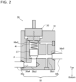
- Fig. 2 is a schematic view illustrating a section of the shut-off valve 30 of the air-conditioning apparatus 100 according to Embodiment 1.
- the shut-off valve 30 includes a block body 31, a flow passage 38 through which the refrigerant flows, and a valve body 37.
- Fig. 2 is a vertical sectional view illustrating a configuration of the block body 31 of the shut-off valve 30.
- the block body 31 includes a base 35, the valve body 37, a spring 41, an indoor-unit-side connection pipe 32a, and an outdoor-unit-side connection pipe 32b.
- the block body 31 includes a refrigerant passage provided therein.
- the refrigerant passage includes a first opening 38a4, a main flow passage 38a1, a main-passage communication part 38a3, a main flow passage 38a2, and a second opening 38a5.
- passages provided in the block body 31 are sometimes collectively referred to as flow passage 38.
- the spring 41 it suffices that the spring 41 is provided as occasion needed in order to enhance a closing force of the valve body 37. Accordingly, the shut-off valve 30 may include no spring 41.
- the shut-off valves 30 of the air-conditioning apparatus 100 according to Embodiment 1 include service ports 50.
- the service ports 50 will be described later with reference to Figs. 4 to 6 , and are thus not illustrated in Figs. 2 and 3 .
- the base 35 is fit in an opening provided in an upper portion of the block body 31 such that the base 35 is visually observable from the outside of the shut-off valve 30.
- the base 35 seals the opening of the block body 31 to prevent a fluid from leaking from the block body 31.
- the valve body 37 is movable in the flow passage 38 to open and close the flow passage 38.
- the valve body 37 is provided in part of the flow passage 38 that extends in an up-down direction.
- the valve body 37 can be moved up and down.
- the valve bodies 37 of all the shut-off valves 30 are moved down to a closed position P where the valve bodies 37 shuts off the passages 38.
- the air-conditioning apparatus 100 includes plural indoor units 2, in some cases, one of the indoor units 2 is in operation and another one of the indoor units 2 is in the stopped state. For example, in the air-conditioning apparatus 100 as illustrated in Fig.
- the indoor units 2a and 2c are in operation and the indoor unit 2b is in the stopped state.
- the valve bodies 37 of the indoor-unit-side shut-off valves 30a-3 and 30a-4 connected to the indoor unit 2b are moved down to the closed position P where the valve bodies 37 shut off the respective passages 38 in the indoor-unit-side shut-off valves 30a-3 and 30a-4.
- the indoor-unit-side connection pipe 32a is fit in the first opening 38a4 provided in the block body 31.
- the outdoor-unit-side connection pipe 32b is fit in the second opening 38a5 provided in the block body 31.
- the indoor-unit-side connection pipe 32a is connected to the refrigerant pipe 10 connected to the indoor unit 2.
- the outdoor-unit-side connection pipe 32b is connected to the refrigerant pipe 10 connected to the outdoor unit 3.
- the flow passage 38 connecting the indoor-unit-side connection pipe 32a and the outdoor-unit-side connection pipe 32b is provided in the block body 31.
- a fluid can flow through the flow passage 38 from the outdoor-unit-side connection pipe 32b toward the indoor-unit-side connection pipe 32a, or from the indoor-unit-side connection pipe 32a toward the outdoor-unit-side connection pipe 32b.
- the flow passage 38 is shut off when the valve body 37 is moved down to the closed position P.
- the flow passage 38 is in the open state when the valve body 37 is located above the closed position P.
- connection pipe 32 the indoor-unit-side connection pipe 32a and the outdoor-unit-side connection pipe 32b are simply referred to as "connection pipe 32" as appropriate in the case where they do not particularly need to be distinguished from each other.
- connection pipe 32 is also referred to as “connection pipe 32" as appropriate in the case where they do not particularly need to be distinguished from each other.
- connection pipe 32 is also made assuming that the term “connection pipe 32" is applicable to both a single connection pipe 32 and plural connection pipes 32.
- the flow passage 38 includes the first opening 38a4, the main flow passage 38a1, the main-passage communication part 38a3, the main flow passage 38a2, and the second opening 38a5.
- the second opening 38a5 is connected to the outdoor-unit-side connection pipe 32b, and serves as an inlet or outlet for fluid.
- the main flow passage 38a1 is a passage extending substantially horizontally from the second opening 38a5.
- the main-passage communication part 38a3 is a passage located between the main flow passage 38a1 and the main flow passage 38a2, and extending upward from an end of the main flow passage 38a1.
- the main flow passage 38a2 is a passage that is L-shaped as a whole.
- the main flow passage 38a2 extends downward from the lower end of the main-passage communication part 38a3, and further extends substantially horizontally.
- the main flow passage 38a2 is connected at one end to the lower end of the main-passage communication part 38a3 as described above, and connected at the other end to the first opening 38a4.
- the first opening 38a4 is connected to the indoor-unit-side connection pipe 32a, and serves as an inlet or outlet for fluid.
- the valve body 37 is moved up and down in the main-passage communication part 38a3 to open and close the space between the main flow passage 38a1 and the main flow passage 38a2.
- a reference sign denoting the flow passage 38 is not indicated in Fig. 2 .
- the communication between the main flow passage 38a1 and the main flow passage 38a2 is shut off when the valve body 37 is located in the closed position P.
- the closed position P of the valve body 37 corresponds to a position where the main-passage communication part 38a3 and the main flow passage 38a2 are connected with each other.
- the main flow passage 38a2 is too narrow in width to allow the valve body 37 to move therein.
- the main flow passage 38a2 is connected with the lower end of the main-passage communication part 38a3. Consequently, when the valve body 37 is moved down in the main-passage communication part 38a3, the valve body 37 cannot be further moved down to a position located below the position where the main-passage communication part 38a3 and the main flow passage 38a2 connect with each other.
- valve body 37 blocks the space between the main-passage communication part 38a3 and the main flow passage 38a2.
- the main flow passage 38a1 is connected to the main-passage communication part 38a3 at a position located above the closed position P of the valve body 37.
- the valve body 37 blocks the space between the main flow passage 38a1 and the main-passage communication part 38a3.
- the air-conditioning apparatus 100 having the above configuration is operated in the cooling operation and in the heating operation, based on the flow of the refrigerant.
- all of the indoor units 2a, 2b, and 2c may perform the cooling operation or all of the indoor units 2a, 2b, and 2c may perform the heating operation.
- the shut-off valves 30 allow flow of the refrigerant.
- the refrigerant changes into gas refrigerant, and then flows into the outdoor heat exchanger 7 through the refrigerant flow switching device 9.
- the gas refrigerant that has flowed into the outdoor heat exchanger 7 exchanges heat with outdoor air to condense while transferring heat to the outdoor air, and thus change into liquid refrigerant.
- the liquid refrigerant flows out from the outdoor heat exchanger 7.
- the liquid refrigerant flows out from the outdoor unit 3.
- the liquid refrigerant that has flowed out from the outdoor unit 3 flows into the outdoor-unit-side connection pipe 32b of the outdoor-unit-side shut-off valve 30b-1.
- the liquid refrigerant that has flowed into the outdoor-unit-side connection pipe 32b of the outdoor-unit-side shut-off valve 30b-1 flows through the flow passage 38 of the outdoor-unit-side shut-off valve 30b-1, and flows out from the indoor-unit-side connection pipe 32a of the outdoor-unit-side shut-off valve 30b-1.
- the liquid refrigerant that has flowed out from the indoor-unit-side connection pipe 32a of the outdoor-unit-side shut-off valve 30b-1 flows through the refrigerant pipe 10, and flows into the outdoor-unit-side connection pipe 32b of each of the indoor-unit-side shut-off valves 30a-1, 30a-3, and 30a-5.
- the liquid refrigerant that has flowed into the outdoor-unit-side connection pipe 32b of each of the indoor-unit-side shut-off valves 30a-1, 30a-3, and 30a-5 flows through the flow passage 38 of that indoor-unit-side shut-off valve, and flows out from the indoor-unit-side connection pipe 32a of the indoor-unit-side shut-off valve.
- the liquid refrigerant that has flowed out from each of the indoor-unit-side shut-off valves 30a-1, 30a-3, and 30a-5 is reduced in pressure by the expansion valve 5 in an associated one of the indoor units 2a, 2b, and 2c, and then flows into an associated one of the indoor heat exchangers 4.
- the refrigerant that has flowed into the indoor heat exchanger 4 exchanges heat with indoor air to receive heat therefrom and evaporate, thereby cooling the indoor air, and thus changes into gas refrigerant.
- the gas refrigerant flows out from the indoor heat exchanger 4.
- the gas refrigerant that has flowed out from each of the indoor heat exchangers 4 flows into the indoor-unit-side connection pipe 32a of an associated one of the indoor-unit-side shut-off valves 30a-2, 30a-4, and 30a-6.
- the gas refrigerant that has flowed into the indoor-unit-side connection pipe 32a of the above indoor-unit-side shut-off valve flows through the flow passage 38 of the above indoor-unit-side shut-off valve, and flows out from the outdoor-unit-side connection pipe 32b of the indoor-unit-side shut-off valve.
- the gas refrigerant that has flowed out form the outdoor-unit-side connection pipe 32b of the indoor-unit-side shut-off valve flows through the refrigerant pipe 10, and flows into the indoor-unit-side connection pipe 32a of the outdoor-unit-side shut-off valve 30b-2.
- the gas refrigerant that has flowed into the indoor-unit-side connection pipe 32a of the outdoor-unit-side shut-off valve 30b-2 flows through the flow passage 38 of the outdoor-unit-side shut-off valve 30b-2, and flows out from the outdoor-unit-side connection pipe 32b of the outdoor-unit-side shut-off valve 30b-2.
- the gas refrigerant that has flowed out from the outdoor-unit-side connection pipe 32b of the outdoor-unit-side shut-off valve 30b-2 flows through the refrigerant pipe 10, and flows into the outdoor unit 3.
- the gas refrigerant that has flowed into the outdoor unit 3 returns to the compressor 6 after flowing through the refrigerant flow switching device 9 and the accumulator 25. In the cooling operation, the circulation of refrigerant as described above is repeated.
- the refrigerant that has flowed out from the outdoor unit 3 flows through the refrigerant pipe 10 and flows into the outdoor-unit-side connection pipe 32b of the outdoor-unit-side shut-off valve 30b-2.
- the refrigerant that has flowed into the outdoor-unit-side connection pipe 32b of the outdoor-unit-side shut-off valve 30b-2 flows through the flow passage 38 of the outdoor-unit-side shut-off valve 30b-2, and flows out from the indoor-unit-side connection pipe 32a of the outdoor-unit-side shut-off valve 30b-2.
- the refrigerant that has flowed out from the indoor-unit-side connection pipe 32a of the outdoor-unit-side shut-off valve 30b-2 flows through the refrigerant pipe 10 and flows into the outdoor-unit-side connection pipe 32b of each of the indoor-unit-side shut-off valves 30a-2, 30a-4, and 30a-6.
- the refrigerant that has flowed into the outdoor-unit-side connection pipe 32b of each of the indoor-unit-side shut-off valves 30a-2, 30a-4, and 30a-6 flows through the flow passage 38 of that indoor-unit-side shut-off valve, and flows out from the indoor-unit-side connection pipe 32a of the indoor-unit-side shut-off valve.
- the refrigerant that has flowed out from the indoor-unit-side connection pipe 32a of the indoor-unit-side shut-off valve flows into the indoor heat exchanger 4 in an associated one of the indoor units 2a to 2c.
- the refrigerant that has flowed into the indoor heat exchanger 4 exchanges heat with indoor air to condense while transferring heat to the indoor air, thereby heating the indoor air, and thus changes into liquid refrigerant.
- the liquid refrigerant then flows out from the indoor heat exchanger 4.
- the liquid refrigerant that has flowed out form the indoor heat exchanger 4 flows through the expansion valve 5 that is provided in an associated one of the indoor units 2a to 2c and that is in the open state, and then flows into the indoor-unit-side connection pipe 32a of an associated one of the indoor-unit-side shut-off valves 30a-1, 30a-3, and 30a-5.
- the liquid refrigerant that has flowed into the indoor-unit-side connection pipe 32a of the above indoor-unit-side shut-off valve flows through the flow passage 38 of the indoor-unit-side shut-off valve, and flows out from the outdoor-unit-side connection pipe 32b of the indoor-unit-side shut-off valve.
- the liquid refrigerant that has flowed out from the outdoor-unit-side connection pipe 32b flows through the refrigerant pipe 10 and flows into the indoor-unit-side connection pipe 32a of the outdoor-unit-side shut-off valve 30b-1.
- the liquid refrigerant that has flowed into the indoor-unit-side connection pipe 32a of the outdoor-unit-side shut-off valve 30b-1 flows through the flow passage 38 of the outdoor-unit-side shut-off valve 30b-1 and flows out from the outdoor-unit-side connection pipe 32b of the outdoor-unit-side shut-off valve 30b-1.
- the liquid refrigerant that has flowed out from the outdoor-unit-side connection pipe 32b of the outdoor-unit-side shut-off valve 30b-1 flows through the refrigerant pipe 10 and flows into the outdoor unit 3.
- the liquid refrigerant that has flowed into the outdoor unit 3 is reduced in pressure by the expansion valve 8 and flows into the outdoor heat exchanger 7.
- the refrigerant that has flowed into the outdoor heat exchanger 7 exchanges heat with indoor air to receive heat therefrom and evaporate and thus gasifies, and the refrigerant flows out from the outdoor heat exchanger 7.
- the refrigerant that has flowed out from the outdoor heat exchanger 7 flows through the refrigerant flow switching device 9 and the accumulator 25 and returns to the compressor 6. In the heating operation, the above circulation of the refrigerant is repeated.
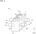
- Fig. 3 is a perspective view illustrating an example of the configuration of the appearance of the shut-off valve unit 300 according to Embodiment 1.
- Fig. 3 illustrates, for the purpose of explanation, an example in which the indoor-unit-side shut-off valves 30a-1 and 30a-2 as illustrated in Fig. 1 are formed as the shut-off valve unit 300.
- the vertical section as illustrated in Fig. 2 corresponds to a portion A indicated by chain double-dashed lines in Fig. 3 .
- the shut-off valve unit 300 may be formed as a single unit made up of three or more shut-off valves 30.
- shut-off valves 30 connected to the same indoor unit 2 can be provided as a shut-off valve unit 300. Therefore, in the air-conditioning apparatus 100 as illustrated in Fig. 1 , the indoor-unit-side shut-off valves 30a-1 and 30a-2 connected to the indoor unit 2a can be provided as a first shut-off valve unit 300; the indoor-unit-side shut-off valves 30a-3 and 30a-4 connected to the indoor unit 2b can be formed as a second shut-off valve unit 300; and the indoor-unit-side shut-off valves 30a-5 and 30a-6 connected to the indoor unit 2c can be formed as a third shut-off valve unit 300.
- the outdoor-unit-side shut-off valves 30b-1 and 30b-2 connected to the outdoor unit 3 can be formed as a single shut-off valve unit 300.
- the shut-off valve unit 300 includes two shut-off valves 30, that is, the indoor-unit-side shut-off valve 30a-1 and the indoor-unit-side shut-off valve 30a-2.
- the block body 31 of the indoor-unit-side shut-off valve 30a-1 and the block body 31 of the indoor-unit-side shut-off valve 30a-2 are formed as a single block body 31A.
- the flow passage 38 of the indoor-unit-side shut-off valve 30a-1 and the flow passage 38 of the indoor-unit-side shut-off valve 30a-2 are arranged side by side in the block body 31A. As illustrated in Fig.
- the block body 31A of the shut-off valve unit 300 has the first opening 38a4 and the second opening 38a5 of the indoor-unit-side shut-off valve 30a-1 and the first opening 38a4 and the second opening 38a5 of the indoor-unit-side shut-off valve 30a-2.
- respective indoor-unit-side connection pipes 32a are connected.
- respective outdoor-unit-side connection pipes 32b are connected.
- the shut-off valves 30 of the air-conditioning apparatus 100 according to Embodiment 1 includes the service ports 50.
- the service port 50 will be described with reference to Figs. 4 to 6 .
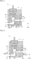
- Figs 4 and 5 are sectional views each schematically illustrating an example of the shut-off valve 30 including the service port 50 according to Embodiment 1.
- Fig. 6 is a perspective view illustrating an example of the configuration of the shut-off valve unit 300 including the service ports 50 in Embodiment 1.
- the service port 50 is provided in the block body 31 of the shut-off valve 30 such that the service port 50 communicates with the flow passage 38. Therefore, the service port 50 communicates with the refrigerant pipe 10 via the flow passage 38.
- the service port 50 has a tip 51 and a connection part 52.
- the tip 51 can be formed to have an opening that allows external equipment to be inserted from the tip 51 into the service port 50. When being inserted from the tip 51 of the service port 50, the external equipment can communicate with the refrigerant pipe 10.
- the tip 51 may be shaped to serve as a joint that allows connection of the external equipment. For example, a push-in joint may be provided as the tip 51. Alternatively, a screwed-threaded joint and a sealing component may be provided as the tip 51.
- connection part 52 of the service port 50 has a tubular shape, and connects the tip 51 of the service port 50 and the flow passage 38 of the shut-off valve 30.
- the external equipment inserted from the tip 51 can be moved to the flow passage 38 of the shut-off valve 30 through the connection part 52.
- Fig. 4 illustrates two service ports 50 that communicates with the first main flow passage 38a1 and the main flow passage 38a2, respectively.
- a first one of the service ports 50 is provided at a location where the first service port 50 communicates with the main flow passage 38a1
- a second one of the service ports 50 is provided at a location where the second service port 50 communicates with the main flow passage 38a2.
- the two service ports 50 can be used to communicate with the indoor-unit-side connection pipe 32a and the outdoor-unit-side connection pipe 32b. That is, when the external equipment is connected with the two service ports 50, it can communicate with the refrigerant pipe 10 connected to the indoor unit 2 and the refrigerant pipe 10 connected to the outdoor unit 3.
- the number of service ports 50 and the installation positions of the service ports 50 are not limited to those as illustrated in Fig. 4 .
- a single service port 50 may be provided in such a manner as to communicate with some portion of the flow passage 38 provided in the block body 31.
- another service port 50 may be provided.
- the service port 50 provided in the flow passage 38 does not necessarily have to protrude from the bottom of the block body 31.
- the service port 50 may protrude from the side or top of the block body 31.
- service port 50 is provided in the block body 31 of the shut-off valve 30.
- service ports 50 may be provided in the indoor-unit-side connection pipe 32a and the outdoor-unit-side connection pipe 32b.
- the service port 50 may be provided in either the indoor-unit-side connection pipe 32a or the outdoor-unit-side connection pipe 32b.
- one service port 50 may be provided in the block body 31, and another service port 50 may be provided in either the indoor-unit-side connection pipe 32a or the outdoor-unit-side connection pipe 32b.
- service ports 50 are provided in the indoor-unit-side connection pipes 32a and the outdoor-unit-side connection pipes 32b of the shut-off valve unit 300.
- respective service ports 50 are provided in all the outdoor-unit-side connection pipes 32b and the indoor-unit-side connection pipes 32a.
- a combination of the number of service ports 50 and the locations of the service ports 50 is not limited to those illustrated in Fig. 6 .
- the number of service ports 50 and the locations of the service port 50 may be combined such that the service port or ports 50 are provided in the following manner: for example, in the service port 50 in the outdoor-unit-side connection pipe 32b of the indoor-unit-side shut-off valve 30a-1 and in the indoor-unit-side connection pipe 32a of the indoor-unit-side shut-off valve 30a-2, respective service ports 50 are provided.
- the service port 50 may be provided in the block body 31A in such a manner as to communicate with the flow passage 38.
- Figs. 4 to 6 illustrate examples in each of which the service port 50 or the service ports 50 are provided in the block body 31, the indoor-unit-side connection pipe 32a, and/or the outdoor-unit-side connection pipe 32b.
- the service port or ports 50 are provided in the shut-off valve 30 at such a location as to communicate with the refrigerant pipe 10, and illustration of the service ports 50 is not limiting.
- the service port or ports 50 may be provided in the base 35 or the valve body 37.
- External equipment for use in maintenance of the air-conditioning apparatus 100 can be directly connected to the tip 51 of the service port 50.
- the maintenance of the air-conditioning apparatus 100 means work such as installation, removal, relocation, repair, modification, and inspection of the air-conditioning apparatus 100.
- external equipment for example, a pressure sensor, a device for drawing refrigerant, a vacuum pump, and a tank for re-filing refrigerant.
- a connection hose may be directly connected to the tip 51. In the case where the external equipment cannot be directly connected to the tip 51, it suffices that the external equipment is connected to a connection hose connected to the tip 51.
- FIG. 7 is a schematic view illustrating an example in which the air-conditioning apparatus 100 according to Embodiment 1 is provided with plural shut-off valves 30.
- Fig. 8 is a schematic view illustrating the case where a refrigerant leak occurs in the air-conditioning apparatus 100 as illustrated in Fig. 7 . It will be described how the service port 50 is used in the case where a refrigerant leak occurs in the air-conditioning apparatus 100 as illustrated in Fig. 7 .
- the indoor-unit-side shut-off valve 30a-1, the indoor-unit-side shut-off valve 30a-2, the outdoor-unit-side shut-off valve 30b-1, and the outdoor-unit-side shut-off valve 30b-2 are provided, whereby it is possible to divide the inside of the air-conditioning apparatus 100 into a first region AR1, a second region AR2, and a third region AR3, and do a service work on the air-conditioning apparatus 100.
- the first region AR1 is a region where the indoor unit 2 is installed.
- the second region AR2 is a region where the refrigerant pipes 10 connecting the indoor unit 2 and the outdoor unit 3 are provided.
- the third region AR3 is a region where the outdoor unit 3 is installed.
- the outdoor unit 3 is provided with a pressure sensor 60.
- the second region AR2 can be further divided into a region where the refrigerant pipe 10 that connects the indoor-unit-side shut-off valve 30a-1 and the outdoor-unit-side shut-off valve 30b-1 is provided and a region where the refrigerant pipe 10 that connects the indoor-unit-side shut-off valve 30a-2 and the outdoor-unit-side shut-off valve 30b-2 is provided.
- the indoor-unit-side shut-off valve 30a-1, the indoor-unit-side shut-off valve 30a-2, the outdoor-unit-side shut-off valve 30b-1, and the outdoor-unit-side shut-off valve 30b-2 have respective service ports 50 each of which is provided at a location where the service port 50 communicates with the indoor-unit-side connection pipe 32a when the flow passage 38 is blocked by the valve body 37.
- each of the shut-off valves 30 are closed.
- the first region AR1, the second region AR2, and the third region AR3 are isolated from each other.
- the pressure sensor 60 may be connected to the service port 50 of the outdoor-unit-side shut-off valve 30b-1 or the outdoor-unit-side shut-off valve 30b-2 that communicates with the third region AR3.
- Fig. 8 illustrates an example in which refrigerant leaks at a refrigerant leak position LP at the refrigerant pipe 10.
- the value detected by the pressure sensor 60 connected to the service port 50 of the outdoor-unit-side shut-off valve 30b-1 is close to the atmospheric pressure.
- the pressure sensor 60 connected to the service port 50 of the outdoor-unit-side shut-off valve 30b-1 is indicated in a dotted pattern.
- the values detected by the pressure sensors 60 connected to the respective service ports 50 of the indoor-unit-side shut-off valve 30a-1, the indoor-unit-side shut-off valve 30a-2, and the outdoor-unit-side shut-off valve 30b-2 are kept constant after deactivation of the air-conditioning apparatus 100.
- the first region AR1 and the third region AR3 can be excluded from regions to be checked. It is therefore possible to decrease the number of regions to be checked to determine a location where a refrigerant leak occurs, thereby shortening the time required to determine the location where the refrigerant leaks occurs, and thus improving the maintainability of the air-conditioning apparatus 100.
- the pressure sensor 60 connected to the service port 50 of the outdoor-unit-side shut-off valve 30b-1 is removed, and then external equipment necessary for repairing the air-conditioning apparatus 100 can be connected to the service port 50.
- Fig. 9 is a schematic view illustrating an example in which external equipment is connected to the service ports 50 as illustrated in Fig. 7 .
- a vacuum pump 61 is connected as external equipment to the service port 50 of the outdoor-unit-side shut-off valve 30b-1.
- the service port 50 of the outdoor-unit-side shut-off valve 30b-1 is provided at a location where the service port 50 communicates with the indoor-unit-side connection pipe 32a. As illustrated in Fig.
- the vacuum pump 61 is connected to the service port 50 of the outdoor-unit-side shut-off valve 30b-1, with the air-conditioning apparatus 100 being in the deactivated state, whereby the refrigerant pipes 10 located in the second region AR2 and extending between the indoor-unit-side shut-off valve 30a-1 and the outdoor-unit-side shut-off valve 30b-1 can be evacuated.
- the vacuum pump 61 as illustrated in Fig. 9 is connected to the service port 50 of the outdoor-unit-side shut-off valve 30b-1, but can also be connected to the service port 50 of any one of the indoor-unit-side shut-off valve 30a-1, the indoor-unit-side shut-off valve 30a-2, and the outdoor-unit-side shut-off valve 30b-2.
- vacuum pumps 61 can be connected to the service port 50 of the outdoor-unit-side shut-off valve 30b-1 and the service port 50 of the outdoor-unit-side shut-off valve 30b-2, and evacuate the refrigerant pipes 10 located in the second region AR2 at the same time. It is therefore possible to shorten the time required to perform evacuation.
- the air-conditioning apparatus 100 includes the outdoor unit 3, the indoor unit 2, the refrigerant pipes 10, and the shut-off valves 30.
- the outdoor unit 3 includes the compressor 6, and the outdoor heat exchanger 7, and generates cooling energy or heating energy.
- the indoor unit 2 includes the indoor heat exchanger 4, and performs an air-conditioning operation with the cooling energy or the heating energy that is generated in the outdoor unit 3.
- the refrigerant pipes 10 are provided between the outdoor unit 3 and the indoor unit 2 and included in a refrigerant circuit in which refrigerant circulates.
- the shut-off valves 30 are provided at the refrigerant pipes 10, and are closed when it is detected that a refrigerant leak occurs.
- the shut-off valves 30 each have the service port 50 that communicates with the refrigerant pipe 10.
- external equipment can be inserted into the refrigerant pipe 10 via the service port 50. That is, it is possible to use necessary external equipment via the service port 50 at the time of performing maintenance of the air-conditioning apparatus 100, and thus possible to improve the maintainability of the air-conditioning apparatus 100.
- the service ports 50 of the air-conditioning apparatus 100 according to Embodiment 1 each have the tip 51 that can be opened and closed and allows external equipment to be attached to and detached from the tip 51.
- the tip 51 is opened when the external equipment is connected to the tip 52.
- a pressure sensor, a device for drawing refrigerant, a vacuum pump, a tank for re-filing refrigerant, and a connection hose can be directly or indirectly connected to the service port 50.
- the shut-off valves 30 according to Embodiment 1 each include the block body 31 and the valve body 37.
- the block body 31 includes the passages 38 that communicate with refrigerant pipes 10.
- each of the flow passage 38 is made to be opened or closed.
- the service port or ports 50 are provided at the block body 31 in such a manner as to communicate with the passages 38. In this configuration, the service ports 50 are provided in the block body 31 that is sturdier than the pipe. Therefore, even when a load acts on the service port 50, the effect of the load on the service port 50 may be reduced.
- the shut-off valves 30 according to Embodiment 1 each include the block body 31, the valve body 37, and the connection pipes 32.
- the block body 31 includes the passages 38 that communicate with the refrigerant pipes 10.
- each of the flow passage 38 is made to be opened or closed.
- the connection pipes 32 are connected to the passages 38, and protrudes from the block body 31.
- the connection pipes 32 are connected to the refrigerant pipes 10.
- the service ports 50 are provided at the connection pipes 32. In the above configuration, the service ports 50 are provided at the connection pipes 32 of the shut-off valves 30, which are pipes directly connected to the refrigerant pipes 10. Therefore, when external equipment needs to be inserted all the way into the refrigerant pipe 10, this insertion can be relatively easily performed. It is therefore possible to further improve the maintainability of the air-conditioning apparatus 100.
- shut-off valves 30 are provided at the refrigerant pipe 10.
- the shut-off valves 30 include the indoor-unit-side shut-off valves 30a and the outdoor-unit-side shut-off valves 30b.
- the indoor-unit-side shut-off valves 30a are located closer to the indoor unit 2 than to the outdoor unit 3.
- the outdoor-unit-side shut-off valves 30b are located closer to the outdoor unit 3 than to the indoor unit 2.
- the plural indoor-unit-side shut-off valves 30a are provided.
- the indoor-unit-side shut-off valves 30a-1 and 30a-2 include the indoor-unit-side shut-off valve 30a-1 that is provided at part of the refrigerant pipe 10 through which the refrigerant passes to flow into the indoor unit 2, and the outdoor-unit-side shut-off valve 30a-2 that is provided at part of the refrigerant pipe 10 through which the refrigerant passes after flowing out from the indoor unit 2.
- the plural outdoor-unit-side shut-off valves 30b are provided.
- the outdoor-unit-side shut-off valves 30b-1 and 30b-2 include the outdoor-unit-side shut-off valve 30b-1 that is provided at part of the refrigerant pipe 10 through which the refrigerant passes to flow into the outdoor unit 3, and the outdoor-unit-side shut-off valve 30b-2 that is provided at part of the refrigerant pipe 10 through which the refrigerant passes after flowing out from the outdoor unit 3.
- the inside of the air-conditioning apparatus 100 is divided into the first region AR1 where the indoor unit 2 is installed, the second region AR2 where the refrigerant pipe 10 connecting the indoor unit 2 and the outdoor unit 3 is provided, and the third region AR3 where the outdoor unit 3 is installed, and in this state, the maintenance of the air-conditioning apparatus 100 can be performed. It is therefore possible to perform maintenance on the first to third regions AR1 to AR3 simultaneously, using the service ports 50 associated with these regions. In addition, in the case of offering service to only a region, maintenance can be performed on only the region, using the service port 50 associated with the region. It is therefore possible to shorten the time required for performing maintenance on the air-conditioning apparatus 100, and further improve the maintainability of the air-conditioning apparatus 100.
- the total length of refrigerant pipes connecting an outdoor unit and plural indoor units can be several hundred meters.
- the amount of refrigerant for use in the air-conditioning apparatus is also increased. Therefore, in an air-conditioning apparatus having refrigerant pipes the total length of which is great, in some cases, it takes a long time to determine a location where a refrigerant leak occurs, since it is necessary to check whether the refrigerant leak occurs, over a relatively large region. For this reason, it may sometimes take time to determine a location where a leak occurs.
- the air-conditioning apparatus 100 in the air-conditioning apparatus 100 according to Embodiment 1, it is possible to perform maintenance on the first to third regions AR1 to AR3 at the same time, which are provided independently of each other, using the service ports 50. Accordingly, it is possible to check the first to third regions AR1 to AR3 simultaneously as to whether a refrigerant leak occurs or not. In addition, it is possible to perform an operation for drawing back refrigerant, an operation for re-filling refrigerant, and an operation for evacuation, on the first to third regions AR1 to AR3, at the same time. Furthermore, it is also possible to perform different maintenance operations on the regions at the same time. The maintainability of the air-conditioning apparatus 100 is thus further improved.
- Fig. 10 is a schematic view illustrating an example of a circuit configuration of the air-conditioning apparatus 100 according to Embodiment 2.
- the air-conditioning apparatus 100 according to Embodiment 2 is a two-pipe type air-conditioning apparatus 100 in which two pipes are provided as refrigerant pipes 10 located between the outdoor unit 3 and the relay unit 17.
- the outdoor-unit-side shut-off valves 30b-1 and 30-b2 are provided at the refrigerant pipes 10 between the outdoor unit 3 and the relay unit 17.
- the air-conditioning apparatus 100 includes the indoor-unit-side shut-off valves 30a-1, 30a-2, 30a-3, 30a-4, 30a-5, and 30a-6 associated with the indoor units 2a, 2b, and 2c.
- the shut-off valves 30 according to Embodiment 2 are the same as those in Embodiment 1, and their descriptions will thus be omitted.
- illustration of dashed lines indicating connection between the controller 20 and the shut-off valve 30 is omitted.
- the air-conditioning apparatus 100 it is possible to activate an indoor unit that performs the cooling operation and an indoor unit that performs the heating operation at the same time.
- a cooling load on the indoor unit that performs the cooling operation exceeds a heating load on the indoor unit that performs the heating operation
- a heating main operation is performed.
- the cooling main operation is performed as the cooling load exceeds the heating load, for example, the number of indoor units that perform the cooling operation is larger than that of indoor units that perform the heating operation.
- the heating main operation is performed as the heating load exceeds the cooling load, the number of indoor units that perform the heating operation is larger than that of indoor units that perform the cooling operation.
- Fig. 10 as an example of the flow of the refrigerant in the cooling main operation, solid arrows indicate the flow of the refrigerant in the case where the indoor units 2a and 2b perform the cooling operation and the indoor unit 2c performs the heating operation. Also, in Fig. 10 , as an example of the flow of the refrigerant in the heating main operation, dashed arrows indicate the flow of the refrigerant in the case where the indoor units 2a and 2b perform the heating operation and the indoor unit 2c performs the cooling operation.
- the outdoor unit 3 includes plural check valves 16a, 16b, 16c, and 16d.
- the check valves 16a, 16b, 16c, and 16d adjust the flow of the refrigerant by preventing backflow of the refrigerant, such that the refrigerant circulates in a single direction.
- the relay unit 17 is provided between the outdoor unit 3 and the indoor-unit-side shut-off valves 30a-1 to 30a-6.
- the outdoor unit 3 and the relay unit 17 are connected by refrigerant pipes 10.
- the refrigerant pipes 10 between the outdoor unit 3 and the relay unit 17 include a refrigerant-pipe communication part 10a and a refrigerant-pipe communication part 10b.
- Refrigerant that flows from the outdoor unit 3 to the relay unit 17 passes through the refrigerant-pipe communication part 10a.
- Refrigerant that flows from the relay unit 17 to the outdoor unit 3 passes through the refrigerant-pipe communication part 10b.
- the outdoor-unit-side shut-off valve 30b-1 is provided at the refrigerant-pipe communication part 10a.
- the outdoor-unit-side shut-off valve 30b-2 is provided at the refrigerant-pipe communication part 10b.
- the indoor-unit-side shut-off valves 30a-1 to 30a-6 are provided at the refrigerant pipes 10 between the indoor unit 2 and the relay unit 17.
- check valves 21a and 21b are provided at the refrigerant pipe 10 extending from the indoor-unit-side shut-off valve 30a-1.
- check valves 21c and 21d are provided at the refrigerant pipe 10 extending from the indoor-unit-side shut-off valve 30a-3.
- check valves 21e and 21f are provided at the refrigerant pipe 10 extending from the indoor-unit-side shut-off valve 30a-5.
- the indoor-unit-side shut-off valve 30a is located closer to an associated one of the indoor units 2 than to the relay unit 17.
- the indoor-unit-side shut-off valve 30a-1 and the indoor-unit-side shut-off valve 30a-2 are located closer to the indoor unit 2a than to the relay unit 17.
- the indoor-unit-side shut-off valve 30a-3 and the indoor-unit-side shut-off valve 30a-4 are located closer to the indoor unit 2b than to the relay unit 17.
- the indoor-unit-side shut-off valve 30a-5 and the indoor-unit-side shut-off valve 30a-6 are located closer to the indoor unit 2c than to the relay unit 17.
- on-off valves 22a and 22b are provided at the refrigerant pipe 10 extending from the indoor-unit-side shut-off valve 30a-2.
- on-off valves 22c and 22d are provided at the refrigerant pipe 10 extending from the indoor-unit-side shut-off valve 30a-4.
- on-off valves 22e and 22f are provided at the refrigerant pipe 10 extending from the indoor-unit-side shut-off valve 30a-6.
- the indoor-unit-side shut-off valves 30a-1 to 30a-6 and the indoor units 2a to 2c are the same in configuration as those according to Embodiment 1, and their descriptions will thus be omitted.
- the indoor units 2b and 2c each include the indoor heat exchanger 4 and the expansion valve 5 as well as the indoor unit 2a, illustration of the indoor heat exchangers 4 and the expansion valves 5 of the indoor units 2b and 2c is thus omitted in Fig. 10 .
- the gas-liquid separator 18, the heat exchangers 23a and 23b, the expansion valves 19a and 19b, the check valves 21a to 21f, the on-off valves 22a to 22f, and the pipes 24a to 24d in the relay unit 17 will be described later; that is, these components are described in the following description concerning the cooling main operation.
- the flow of the refrigerant in the cooling main operation will be described below. With reference to the solid arrows in Fig. 10 , the following description is made by referring to by way of example the case where the indoor units 2a and 2b perform the cooling operation and the indoor unit 2c performs the heating operation.
- the refrigerant is compressed in the compressor 6 to change into gas refrigerant, and the gas refrigerant passes through the refrigerant flow switching device 9 and flows into the outdoor heat exchanger 7.
- the gas refrigerant that has flowed into the outdoor heat exchanger 7 exchanges heat with outdoor air to condense while transferring heat to the outdoor air, thereby changing into two-phase gas-liquid refrigerant.
- the two-phase gas-liquid refrigerant then flows out from the outdoor heat exchanger 7.
- the two-phase gas-liquid refrigerant that has flowed out form the outdoor heat exchanger 7 passes through the expansion valve 8 and the check valve 16a, and then flows out from the outdoor unit 3.
- the two-phase gas-liquid refrigerant that has flowed out from the outdoor unit 3 passes through the refrigerant-pipe communication part 10a and the outdoor-unit-side shut-off valve 30b-1 and flows into the relay unit 17.
- the two-phase gas-liquid refrigerant that has flowed into the relay unit 17 flows into the gas-liquid separator 18, and is separated into gas refrigerant and liquid refrigerant.
- the gas refrigerant flows into the pipe 24a, and the liquid refrigerant flows into the pipe 24b.
- the on-off valves 22b, 22d, and 22f are connected.
- the heat exchanger 23b, the expansion valve 19a, the heat exchanger 23a, and the check valves 21b, 21d, and 21f are connected.
- the gas refrigerant that has flowed into the pipe 24a flows toward the indoor unit 2c which performs the heating operation.
- the gas refrigerant that has flowed into the pipe 24a passes through the on-off valve 22f and through the indoor-unit-side shut-off valve 30a-6 associated with the indoor unit 2c, and then flows into the indoor unit 2c.
- the gas refrigerant that has flowed into the indoor unit 2c flows into the indoor heat exchanger 4.
- the gas refrigerant that has flowed into the indoor heat exchanger 4 of the indoor unit 2c exchanges heat with indoor air to condense while transferring heat to the indoor air, thereby heating the indoor air.
- the gas refrigerant changes into liquid refrigerant, and the liquid refrigerant flows out from the indoor heat exchanger 4.
- the liquid refrigerant that has flowed out from the indoor heat exchanger 4 is reduced in pressure by the expansion valve 5, and then flows out from the indoor unit 2c.
- the liquid refrigerant that has flowed out from the indoor unit 2c passes through the indoor-unit-side shut-off valve 30a-5 and flows into the relay unit 17.
- the liquid refrigerant that has flowed into the relay unit 17 passes through the check valve 21e and flows into the pipe 24d.
- the pipe 24d is connected to the pipe 24b located close to the outlet of the expansion valve 19a. Therefore, in the pipe 24b, the liquid refrigerant that has flowed into the pipe 24d joins the liquid refrigerant that has been subjected to separation by the gas-liquid separator 18 and then expanded by the expansion valve 19a.
- the liquid refrigerant that has been obtained through separation by the gas-liquid separator 18 and flowed into the pipe 24b flows through the heat exchanger 23b and the expansion valve 19a, and as a result, is subcooled.
- the subcooled liquid refrigerant joins the liquid refrigerant flowing from the pipe 24d.
- the liquid refrigerant obtained by the above joining is further subcooled in the heat exchanger 23a, and then branches off. Branching part of the refrigerant flows from the pipe 24b into the pipe 24c. Remaining part of the liquid refrigerant that has not flowed into the pipe 24c flows through the pipe 24b and flows toward one of the indoor unit 2a and the indoor unit 2b that performs the cooling operation.
- the pipe 24c is connected with the expansion valve 19b and the heat exchangers 23a and 23b.
- the pipe 24c is connected with a pipe 24e at a location close to the outlet of the heat exchanger 23b.
- the refrigerant After flowing out from the heat exchanger 23b, the refrigerant joins the gas refrigerant flowing in the pipe 24e.
- the refrigerant obtained through the above joining then flows through the outdoor-unit-side shut-off valve 30b-2 and the refrigerant-pipe communication part 10b, and flows into the outdoor unit 3.
- the above remaining part of the liquid refrigerant that has not flowed into the pipe 24c after flowing out from the heat exchanger 23a flows through the check valve 21b or the check valve 21d, then flows through the indoor-unit-side shut-off valve 30a-1 associated with the indoor unit 2a or through the indoor-unit-side shut-off valve 30a-3 associated with the indoor unit 2b, and flows into the indoor unit 2a or the indoor unit 2b.
- the liquid refrigerant that has flowed into the indoor unit 2a or the indoor unit 2b is reduced in pressure by the expansion valve 5, and then flows into the indoor heat exchanger 4.
- the liquid refrigerant that has flowed into the indoor heat exchanger 4 exchanges heat with indoor air to receive heat therefrom and evaporate, thereby cooling the indoor air.
- the liquid refrigerant changes into gas refrigerant, and the gas refrigerant flows out from the indoor heat exchanger 4.
- the gas refrigerant that has flowed out from the indoor heat exchanger 4 flows through the indoor-unit-side shut-off valve 30a-2 or the indoor-unit-side shut-off valve 30a-4 and flows into the relay unit 17.
- the gas refrigerant that has flowed into the relay unit 17 flows through the on-off valve 22a or the on-off valve 22c and flows into the pipe 24e.
- the gas refrigerant that has flowed into the pipe 24e joins the refrigerant flowing in the pipe 24c, and the refrigerant obtained through the joining then flows through the outdoor-unit-side shut-off valve 30b-2 and the refrigerant-pipe communication part 10b and flows into the outdoor unit 3.
- Refrigerant compressed in the compressor 6 flows through the refrigerant flow switching device 9 and the check valve 16b, flows out from the outdoor unit 3, then flows through the refrigerant-pipe communication part 10a and the outdoor-unit-side shut-off valve 30b-1 , and flows into the relay unit 17.
- the refrigerant that has flowed into the relay unit 17 flows into the gas-liquid separator 18 and is separated into gas refrigerant and liquid refrigerant.
- the gas refrigerant flows into the pipe 24a, and the liquid refrigerant flows into the pipe 24b.
- the gas refrigerant that has flowed into the pipe 24a flows toward one of the indoor unit 2a and the indoor unit 2b that performs the heating operation. More specifically, the gas refrigerant that has flowed into the pipe 24a passes through the on-off valve 22b or the on-off valve 22d, then flows through the indoor-unit-side shut-off valve 30a-2 associated with the indoor unit 2a or through the indoor-unit-side shut-off valve 30a-4 associated with the indoor unit 2b, and flows into the indoor unit 2a or the indoor unit 2b.
- the gas refrigerant that has flowed into the indoor unit 2a or the indoor unit 2b flows into the indoor heat exchanger 4.
- the gas refrigerant that has flowed into the indoor heat exchanger 4 of the indoor unit 2a or the indoor unit 2b exchanges heat with indoor air to condense while transferring heat to the indoor air, thereby heating the indoor air.
- the gas refrigerant changes into liquid refrigerant, and the liquid refrigerant flows out from the indoor heat exchanger 4.
- the liquid refrigerant that has flowed out from the indoor heat exchanger 4 is reduced in pressure by the expansion valve 5 of the indoor unit 2a or the indoor unit 2b, and then flows out from the indoor unit 2a or the indoor unit 2b.
- the liquid refrigerant that has flowed out from the indoor unit 2a or the indoor unit 2b flows through the indoor-unit-side shut-off valve 30a-1 or the indoor-unit-side shut-off valve 30a-3 and flows into the relay unit 17.
- the liquid refrigerant that has flowed into the relay unit 17 flows through the check valve 21a or the check valve 21c and flows into the pipe 24d.
- the pipe 24d is connected to the pipe 24b, and the liquid refrigerant that has flowed into the pipe 24d thus joins, in the pipe 24b, the liquid refrigerant that has been obtained through separation by the gas-liquid separator 18 and expanded by the expansion valve 19a.
- the liquid refrigerant flowing from the pipe 24d joins the liquid refrigerant that has flowed into the pipe 24b after being obtained through the separation by the gas-liquid separator 18.
- the liquid refrigerant obtained through the separation by the gas-liquid separator 18 flows through the heat exchanger 23b and the expansion valve 19a and is subcooled.
- the subcooled liquid refrigerant joins the liquid refrigerant flowing from the pipe 24d.
- the liquid refrigerant obtained through the above joining is further subcooled in the heat exchanger 23a, and branches off. Then, branching part of the liquid refrigerant flows from the pipe 24b into the pipe 24c.
- the pipe 24c is connected to the pipe 24e, and the above branching part of the liquid refrigerant that has flowed into the pipe 24c passes through the expansion valve 19b and the heat exchangers 23a and 23b and then flows into the pipe 24e.
- the refrigerant that has flowed into the pipe 24e passes through the outdoor-unit-side shut-off valve 30b-2 and the refrigerant-pipe communication part 10b and flows into the outdoor unit 3.
- Remaining part of the liquid refrigerant that has not flowed into the pipe 24c flows through the pipe 24b and flows toward the indoor unit 2c, which performs the cooling operation.
- the above remaining part of the liquid refrigerant that has not flowed into the pipe 24c passes through the check valve 21f, then passes through the indoor-unit-side shut-off valve 30a-5 associated with the indoor unit 2c, and flows into the indoor unit 2c.
- the liquid refrigerant that has flowed into the indoor unit 2c is reduced in pressure by the expansion valve 5 and then flows into the indoor heat exchanger 4.
- the liquid refrigerant that has flowed into the indoor heat exchanger 4 exchanges heat with indoor air to receive heat therefrom and evaporate, thereby cooling the indoor air.
- the liquid refrigerant changes into gas refrigerant, and the gas refrigerant flows out from the indoor heat exchanger 4.
- the gas refrigerant that has flowed out form the indoor heat exchanger 4 flows out from the indoor unit 2c, passes through the indoor-unit-side shut-off valve 30a-6, and flows into the relay unit 17.
- the gas refrigerant that has flowed into the relay unit 17 passes through the on-off valve 22e and flows into the pipe 24e.
- the gas refrigerant that has flowed into the pipe 24e joins the refrigerant flowing in the pipe 24c, then passes through the outdoor-unit-side shut-off valve 30b-2 and the refrigerant-pipe communication part 10b, and flows into the outdoor unit 3.
- the gas refrigerant that has flowed from the relay unit 17 into the outdoor unit 3 through the outdoor-unit-side shut-off valve 32b-2 passes through the check valve 16c, the expansion valve 8, and the outdoor heat exchanger 7, and is completely gasified.
- the completely gasified refrigerant returns to the compressor 6 through the refrigerant flow switching device 9 and the accumulator 25. In the heating main operation, the above circulation of the refrigerant is repeated.
- each of the shut-off valves 30 is closed as described above regarding Embodiment 1.
- the region where each indoor unit 2 is located, the region where the relay unit 17 is located, and the region where the outdoor unit 3 is located are isolated from each other as independent regions.
- external equipment such as a pressure sensor or a vacuum pump is connected to the shut-off valve 30, whereby it is possible to determine the location at which the refrigerant leak occurs, and perform maintenance.
- a refrigerant leak occurs in the vicinity of the check valve 21a that is provided as illustrated in Fig.
- a detection value obtained by the pressure sensor connected to the indoor-unit-side shut-off valve 30a-1 is close to the atmospheric pressure. Therefore, at the time of determining the location at which the refrigerant leak occurs, it is possible to shorten the time required for the checking by starting the checking from part of the refrigerant pipe 10 that is close to the indoor-unit-side shut-off valve 30a-1.
- devices for drawing refrigerant are connected to respective indoor-unit side shut-off valves, that is, the indoor-unit-side shut-off valves 30a-1 to 30a-6, to draw back the refrigerant.
- the indoor-unit-side shut-off valves 30a-1 to 30a-6 By applying this way, it is possible to reduce the amount of time required to draw back the refrigerant.
- vacuum pumps are connected to plural shut-off valves 30. Thus, they can be evacuated at the same time. It is therefore possible to reduce the time that is required for maintenance from the time at which refrigerant leaks from the air-conditioning apparatus 100.
- the plural indoor units 2 is provided; the relay unit 17 is installed between the outdoor unit 3 and the indoor units 2a to 2c, and switches the flow passage to be used in the refrigerant circuit between plural flow passages; the outdoor unit 3, the relay unit 17, and the indoor units 2a to 2c are connected by the refrigerant pipes 10; and for the indoor units 2a to 2c, the respective indoor-unit-side shut-off valves 30a are provided, and each of the indoor-unit-side shut-off valves 30a is located closer to an associated one of the indoor units 2 than to the relay unit 17.
- the inside of the air-conditioning apparatus 100 is divided into a region where the outdoor unit 3 is installed, a region located between the relay unit 17 and the indoor unit 2, a region where the indoor unit 2a is installed, a region where the indoor unit 2b is installed, and a region where the indoor unit 2c is installed, whereby those regions can be subjected to maintenance independently of each other. It is therefore possible to perform maintenance on the above regions simultaneously, and thus reduce the time required for maintenance on the air-conditioning apparatus 100. Accordingly, the maintainability of the air-conditioning apparatus 100 is improved.
- the shut-off valves 30 and the air-conditioning apparatus 100 according to Embodiment 3 will be described below.
- the air-conditioning apparatus 100 according to Embodiment 3 plural relay units 17 are provided between the outdoor unit 3 and the plural indoor units 2, and the shut-off valves 30 include relay-unit-side shut-off valves 30c.
- the air-conditioning apparatus 100 of Embodiment 3 is different in configuration from the air-conditioning apparatus 100 of Embodiment 1.
- components that are the same as those in Embodiment 1 and/or Embodiment 2 will be denoted by the same reference signs, and their descriptions will thus be omitted.
- Fig. 11 is a schematic view illustrating an example of a circuit configuration of the air-conditioning apparatus 100 of Embodiment 3.
- the air-conditioning apparatus 100 of Embodiment 3 is a three-pipe air-conditioning apparatus 100 in which three pipes are provided as refrigerant pipes 10 between the outdoor unit 3 and relay units 17a and 17b.
- the refrigerant pipes 10 between the outdoor unit 3 and the relay units 17a and 17b are a refrigerant-pipe communication part 10a, a refrigerant-pipe communication part 10b, and a refrigerant-pipe communication part 10c. It should be noted that in Fig.
- relay unit 17a detailed illustration of the circuits of the relay unit 17a, the relay unit 17b, the outdoor unit 3, and indoor units 2b, 2c, and 2d is omitted, and dashed lines representing connection relationships between the controller 20 and the shut-off valves 30 are omitted.
- the relay unit 17a and the relay unit 17b are each simply referred to as “relay unit 17" as appropriate when they do not particularly need to be distinguished from each other. Also, the following description is also made assuming that the term "relay unit 17" is applicable to both a single relay unit 17 and plural relay units 17.
- Outdoor-unit-side shut-off valves 30b-1, 30b-2, and 30b-3 are provided between the outdoor unit 3 and the relay units 17a and 17b.
- the outdoor-unit-side shut-off valve 30b-1 is provided at the refrigerant-pipe communication part 10a.
- the outdoor-unit-side shut-off valve 30b-2 is provided at the refrigerant-pipe communication part 10b.
- the outdoor-unit-side shut-off valve 30b-3 is provided at the refrigerant-pipe communication part 10c.
- the outdoor-unit-side shut-off valves 30b-1 to 30b-3 are located closer to the outdoor unit 3 than to the relay unit 17.
- the relay-unit-side shut-off valves 30c are provided between the outdoor unit 3 and the relay units 17a and 17b.
- the relay-unit-side shut-off valves 30c, as well as the indoor-unit-side shut-off valves 30a and the outdoor-unit-side shut-off valves 30b, are similar in configuration to the shut-off valves 30 according to Embodiment 1.
- the shut-off valves 30 include the relay-unit-side shut-off valves 30c.
- relay-unit-side shut-off valves 30c-1, 30c-2, 30c-3, 30c-4, 30c-5, and 30c-6 are provided.
- relay-unit-side shut-off valves 30c-1 to 30c-6 are simply referred to as “relay-unit-side shut-off valves 30c" as appropriate when they do not particularly need to be distinguished from each other, and the following description is also made assuming that the term “relay-unit-side shut-off valve 30c” is applicable to both a single relay-unit-side shut-off valve 30c and plural relay-unit-side shut-off valves 30c.
- the relay-unit-side shut-off valves 30c-1, 30c-2, and 30c-3 are associated with the relay unit 17a.
- the relay-unit-side shut-off valves 30c-4, 30c-5, and 30c-6 are associated with the relay unit 17b.
- the relay-unit-side shut-off valve 30c are each provided at the refrigerant pipe 10 connecting the outdoor unit 3 and the relay unit 17, at a location close to an associated one of the relay units 17. That is, the relay-unit-side shut-off valves 30c-1 to 30c-3 are located closer to the relay unit 17a than to the outdoor unit 3.
- the relay-unit-side shut-off valves 30c-4 to 30c-6 are located closer to the relay unit 17b than to the outdoor unit 3.
- the air-conditioning apparatus 100 includes plural indoor units 2a, 2b, 2c, and 2d.
- the indoor unit 2a, 2b, 2c, and 2d are provided in spaces 1a, 1b, 1c, and 1d, respectively, which are air-conditioning target spaces.
- Refrigerant leak detection devices 15a, 15b, 15c, and 15d are provided in the spaces 1a, 1b, 1c, and 1d, respectively, to detect a refrigerant leak.
- the refrigerant leak detection devices 15a to 15d according to Embodiment 3 are the same as the refrigerant leak detection device 15 according to Embodiment 1, and their descriptions will thus be omitted.
- the indoor units 2a and 2b are connected to the relay unit 17a.
- the indoor units 2c and 2d are connected to the relay unit 17b.
- the refrigerant pipe 10 between the indoor unit 2a and the relay unit 17a is provided with the indoor-unit-side shut-off valves 30a-1 and 30a-2.
- the indoor-unit-side shut-off valves 30a-3 and 30a-4 are provided.
- the indoor-unit-side shut-off valves 30a-5 and 30a-6 are provided.
- the indoor-unit-side shut-off valves 30a-7 and 30a-8 are provided at the refrigerant pipes 10 between the indoor unit 2d and the relay unit 17b.
- the configurations of the shut-off valves 30 according to Embodiment 3 are the same as those according to Embodiment 1, and their descriptions will thus be omitted.
- the air-conditioning apparatus 100 includes the relay-unit-side shut-off valves 30c. As a result, regions where the respective indoor units 2 are installed, regions where the respective relay units 17 are installed, regions located between the relay units 17 and the outdoor unit 3, and a region where the outdoor unit 3 is located are isolated from each other as independent regions.
- a detection value obtained by a pressure sensor connected to any one of the outdoor-unit-side shut-off valve 30b-1, the relay-unit-side shut-off valve 30c-1, and the relay-unit-side shut-off valve 30c-4 can be considered to be close to the atmospheric pressure. Therefore, it is possible to shorten the time required for checking to determine part of the refrigerant pipe 10 where the refrigerant leak occurs, by starting the checking from an area close to the shut-off valve 30 connected to the pressure sensor that obtains the detection value close to the atmospheric pressure. It is therefore possible to reduce the time required for the checking.
- the device for drawing refrigerant connected to each of the outdoor-unit-side shut-off valve 30b-1, the relay-unit-side shut-off valve 30c-1, and the relay-unit-side shut-off valve 30c-4 to draw back refrigerant.
- vacuum pumps are connected to the outdoor-unit-side shut-off valve 30b-1, the relay-unit-side shut-off valve 30c-1 , and the relay-unit-side shut-off valve 30c-4 to enable simultaneous evacuation to be performed. It is therefore possible to reduce the time required for maintenance that is performed after refrigerant leaks from the air-conditioning apparatus 100. Therefore, the maintainability of the air-conditioning apparatus 100 can be further improved.
- the shut-off valves 30 according to Embodiment 3 include the plural indoor-unit-side shut-off valves 30a, the plural outdoor-unit-side shut-off valves 30b, and plural relay-unit-side shut-off valves 30c. It is therefore possible to divide the inside of the air-conditioning apparatus 100 according to Embodiment 3 into a region where the indoor unit 2a is installed, a region where the indoor unit 2b is installed, a region where the indoor unit 2c is installed, a region where the indoor unit 2d is installed, a region where the relay unit 17a is installed, a region where the relay unit 17b is installed, and a region located between the outdoor unit 3 and the relay unit 17.
- each of the above regions can be subjected to maintenance as an independent region.
- existing air-conditioning apparatuses including a relay unit since the total length of refrigerant pipes is great and the amount of refrigerant to be used is large, in some cases, it takes time to perform maintenance such as an operation to determine the location where a refrigerant leak occurs, an operation to draw back an operation to re-fill refrigerant, and an operation to evacuate refrigerant pipes.
Landscapes
- Engineering & Computer Science (AREA)
- Mechanical Engineering (AREA)
- General Engineering & Computer Science (AREA)
- Physics & Mathematics (AREA)
- Thermal Sciences (AREA)
- Chemical & Material Sciences (AREA)
- Combustion & Propulsion (AREA)
- Other Air-Conditioning Systems (AREA)
Abstract
Description
- The present disclosure relates to an air-conditioning apparatus including a shut-off valve.
-
Patent Literature 1 discloses an air-conditioning apparatus that closes, when detecting a leak of refrigerant, a solenoid valve and a shut-off valve in order to reduce further occurrence of the refrigerant leak. To be more specific, the air-conditioning apparatus according toPatent Literature 1 includes an electromagnetic expansion valve and a shut-off valve that are provided in the following manner. The electromagnetic expansion valve is provided in a refrigerant circuit that is located between an outdoor heat exchanger and an indoor heat exchanger such that no compressor is interposed between the outdoor heat exchanger and the indoor heat exchanger. The shut-off valve is provided in a refrigerant circuit that is located between an outdoor heat exchanger and an indoor heat exchanger, with a compressor interposed between the outdoor heat exchanger and the indoor heat exchanger.Patent Literature 1 proposes use of a controller that closes the electromagnetic expansion valve to cause refrigerant to collect on an outdoor heat exchanger side, when a leak of refrigerant is detected, and then closes the shut-off valve. - Patent Literature 1:
Japanese Unexamined Patent Application Publication No. 2000-97527 - In some cases, if refrigerant leaks from an air-conditioning apparatus, further occurrence of such a refrigerant leak is reduced using, for example, the controller described in
Patent Literature 1, the air-conditioning apparatus is stopped, and a component of the air-conditioning apparatus is then repaired or replaced by a new one. In this case, it is necessary to find a location at which the refrigerant leak occurs. Furthermore, in the case of repairing or replacing a component of the air-conditioning apparatus, in some cases, the refrigerant is drawn out from the air-conditioning apparatus, the component is repaired or replaced by a new one, and refrigerant is then re-filled into the air-conditioning apparatus. This, however, causes the following problem related to the maintainability of the air-conditioning apparatus: refrigerant pipes have no part that allows connection of external equipment such as, a temperature sensor, a pressure sensor, a pump for drawing the refrigerant, a pump for re-filing refrigerant, and a vacuum pump. Inevitably, it takes time to, for example, find a location where a refrigerant leak occur, draw out refrigerant, and re-fill refrigerant. - The present disclosure is applied in view of the above circumstances, and relates to an air-conditioning apparatus that is improved in maintainability.
- An air-conditioning apparatus according to an embodiment of the present disclosure includes: an outdoor unit including a compressor and an outdoor heat exchanger, and configured to generate cooling energy or heating energy; an indoor unit including an indoor heat exchanger, and configured to perform an air-conditioning operation with the cooling energy or the heating energy that is generated by the outdoor unit; a refrigerant pipe provided between the outdoor unit and the indoor unit, and forming a refrigerant circuit in which refrigerant circulates; and a shut-off valve provided at the refrigerant pipe, and configured to be closed when a refrigerant leak is detected. The shut-off valve includes a service port communicating with the refrigerant pipe.
- The air-conditioning apparatus according to an embodiment of the present disclosure includes a shut-off valve having a service port communicating with a refrigerant pipe. It is therefore possible to connect external equipment with the refrigerant pipe by attaching the external equipment to the service port. Thus, maintenance can be performed on the air-conditioning apparatus, with the external equipment attached to the service port, whereby the maintainability of the air-conditioning apparatus can be improved.
-
- [
Fig. 1] Fig. 1 is a schematic view illustrating an example of a circuit configuration of an air-conditioning apparatus according toEmbodiment 1. - [
Fig. 2] Fig. 2 is a schematic view illustrating a section of a shut-off valve of the air-conditioning apparatus according toEmbodiment 1. - [
Fig. 3] Fig. 3 is a perspective view illustrating an example of the configuration of the appearance of a shut-off valve unit of the air-conditioning apparatus according toEmbodiment 1. - [
Fig. 4] Fig. 4 is a sectional view schematically illustrating an example of the shut-off valve having a service port in Embodiment 1 - [
Fig. 5] Fig. 5 is a sectional view schematically illustrating another example of the shut-off valve having the service port inEmbodiment 1. - [
Fig. 6] Fig. 6 is a perspective view illustrating an example of the configuration of the shut-offvalve unit 300 including theservice port 50 inEmbodiment 1. - [
Fig. 7] Fig. 7 is a schematic view illustrating an example in which the air-conditioning apparatus according toEmbodiment 1 is provided with plural shut-off valves. - [
Fig. 8] Fig. 8 is a schematic view illustrating the case where a refrigerant leak occurs in the air-conditioning apparatus as illustrated inFig. 7 . - [
Fig. 9] Fig. 9 is a schematic view illustrating an example in which external equipment is connected to the service ports as illustrated inFig. 7 . - [
Fig. 10] Fig. 10 is a schematic view illustrating an example of a circuit configuration of an air-conditioning apparatus according toEmbodiment 2. - [
Fig. 11] Fig. 11 is a schematic view illustrating an example of a circuit configuration of an air-conditioning apparatus according toEmbodiment 3. - Air-conditioning apparatuses according to the embodiments will be described below with reference to the drawings. Descriptions of the present disclosure that concern the embodiments described below are not limiting but various modifications can be made without departing from the scope and spirit of the present disclosure. The present disclosure may encompass all possible combinations of configurations as described below regarding the embodiments. The drawings illustrate examples of configurations of the air-conditioning apparatuses, and do not limit the configurations described in the present disclosure. Although directional terms (for example, "upper" and "lower") are used as appropriate in order that the embodiments be more easily understood, they are not limiting. In addition, in each of the figures in the drawings, components that are the same as or equivalent to those in a previous figure or previous figures are denoted by the same reference signs. The same is true of the entire text of the specification. In each of the figures, relative dimensions, shapes, or other features of components may differ from actual ones.
-
Fig. 1 is a schematic view illustrating an example of a circuit configuration of an air-conditioning apparatus 100 according toEmbodiment 1. The air-conditioning apparatus 100 as illustrated inFig. 1 includes anoutdoor unit 3, pluralindoor units conditioning apparatus 100 as illustrated inFig. 1 includes theindoor units conditioning apparatus 100 may include a single indoor unit. In addition, the air-conditioning apparatus 100 may be configured to perform only the cooling operation or only the heating operation. In this case, the air-conditioning apparatus 100 does not include the refrigerant flow switching device 9 as illustrated inFig. 1 . - As illustrated in
Fig. 1 , the air-conditioning apparatus 100 according toEmbodiment 1 includes theoutdoor unit 3 serving as a heat source unit; theindoor units valves 30 provided between theoutdoor unit 3 and theindoor units valve 30 includes an indoor-unit-side shut-offvalve 30a provided close to theindoor units 2, and an outdoor-unit-side shut-offvalve 30b provided close to theoutdoor unit 3. Theoutdoor unit 3, the outdoor-unit-side shut-offvalve 30b, the indoor-unit-side shut-offvalve 30a, and each of theindoor units refrigerant pipes 10. As a result, a refrigerant circuit is formed in which refrigerant circulates through therefrigerant pipes 10. InFig. 1 , solid arrows each indicate the flow of the refrigerant in the cooling operation, and dashed arrows each indicate the flow of the refrigerant in the heating operation. In the following description, a side toward which the refrigerant moves along the flow direction is referred to as a downstream side. That is, the refrigerant flows from an upstream side toward the downstream side. The refrigerant to be used can be considered to be R32 refrigerant, but is not limited to the R32 refrigerant. The flow of the refrigerant in the cooling operation and that in the heating operation will be described later. - In the following description, the indoor-unit-side shut-off
valve 30a and the outdoor-unit-side shut-offvalve 30b are each simply referred to as "shut-offvalve 30" as appropriate in the case where they do not particularly need to be distinguished from each other. The following description is also made assuming that the term "shut-offvalve 30" is applicable to both a single shut-offvalve 30 and plural shut-offvalves 30. - The air-
conditioning apparatus 100 includes indoor-unit-side shut-offvalves 30a that are provided atrespective refrigerant pipes 10, that is, therefrigerant pipe 10 connected to theindoor unit 2a, therefrigerant pipe 10 connected to theindoor unit 2b, and therefrigerant pipe 10 connected to theindoor unit 2c. To be more specific, as illustrated inFig. 1 , indoor-unit-side shut-offvalves 30a-1 and 30a-2 are associated with theindoor unit 2a; the indoor-unit-side shut-offvalves 30a-3 and 30a-4 are associated with theindoor unit 2b; and the indoor-unit-side shut-offvalves 30a-5 and 30a-6 are associated with theindoor unit 2c. In the following description, the indoor-unit-side shut-offvalves 30a-1 to 30a-6 are each simply referred to as "indoor-unit-side shut-offvalve 30a" as appropriate in the case where they do not particularly need to be distinguished from each other. The following description is also made assuming that the term "indoor-unit-side shut-offvalve 30a" is applicable to both a single indoor-unit-side shut-offvalve 30a and plural indoor-unit-side shut-offvalves 30a. - The air-
conditioning apparatus 100 includes outdoor-unit-side shut-offvalves 30b provided at respectiverefrigerant pipes 10 connected to theoutdoor unit 3. To be more specific, as illustrated inFig. 1 , outdoor-unit-side shut-offvalves 30b-1 and 30b-2 are provided at respectiverefrigerant pipes 10 connected to theoutdoor unit 3. In the following description, the outdoor-unit-side shut-offvalve 30b-1 and the outdoor-unit-side shut-offvalve 30b-2 are each simply referred to as "outdoor-unit-side shut-offvalve 30b" as appropriate in the case where they do not particularly need to be distinguished from each other. The following description is also made assuming that the term "outdoor-unit-side shut-offvalve 30b" is applicable to both a single outdoor-unit-side shut-offvalve 30b and plural outdoor-unit-side shut-offvalves 30b. - As illustrated in
Fig. 1 , theoutdoor unit 3 includes acompressor 6, anoutdoor heat exchanger 7, anexpansion valve 8, the refrigerant flow switching device 9, and anaccumulator 25. Thecompressor 6 compresses refrigerant to change it into high-temperature and high-pressure refrigerant, and discharges the high-temperature and high-pressure refrigerant. - The
outdoor heat exchanger 7 causes heat exchange to be performed between the refrigerant and air (hereinafter referred to as "outdoor air" as appropriate) supplied by an air-sending device such as a fan (not illustrated). Specifically, in the cooling operation, theoutdoor heat exchanger 7 serves as a condenser that transfers the heat of the refrigerant to the outdoor air to thereby condense the refrigerant. In the heating operation, theoutdoor heat exchanger 7 serves as an evaporator that evaporates the refrigerant to thereby cool the outdoor air with the heat of vaporization. - The refrigerant flow switching device 9 is, for example, a four-way valve. The refrigerant flow switching device 9 is capable of switching the operation of the air-
conditioning apparatus 100 between the cooling operation and the heating operation by switching the flow direction of the refrigerant between plural flow directions. The refrigerant flow switching device 9 is not limited to the four-way valve but may be a combination of two-way valves, three-way valves, or other valves. - The
accumulator 25 is connected to a suction side of thecompressor 6. By the switching operation of the refrigerant flow switching device 9, theaccumulator 25 is connected to the downstream side of theoutdoor heat exchanger 7 in the heating operation. Theaccumulator 25 is connected to the downstream side of anindoor heat exchanger 4 in the cooling operation. Theaccumulator 25 is a container that stores surplus refrigerant, and absorbs the difference in refrigerant flow rate between the cooling operation and the heating operation. Theoutdoor unit 3 may include noaccumulator 25. - The
expansion valve 8 reduces the pressure of refrigerant that flows from theindoor units conditioning apparatus 100 is used for the cooling operation only, theoutdoor unit 3 may include noexpansion valve 8. In the case where theindoor units respective expansion valves 5, as a configuration in which noexpansion valve 8 is provided, theexpansion valve 5 may be used to fulfill the function of theexpansion valve 8. - The
indoor units spaces indoor units spaces refrigerant pipe 10. Theindoor units indoor heat exchangers 4 andrespective expansion valves 5. AlthoughFig. 1 does not illustrate circuit configurations of theindoor units indoor unit 2a. In the following description, theindoor units indoor unit 2" as appropriate in the case where they do not particularly be distinguished from each other. Furthermore, the following description is also made assuming that the term "indoor unit 2" is applicable to both a singleindoor unit 2 and pluralindoor units 2. - The
indoor heat exchanger 4 in each of theindoor units spaces indoor heat exchanger 4 operates as an evaporator to perform the cooling operation by cooling the air in the associated one of thespaces indoor heat exchanger 4 operates as a condenser to perform the heating operation by heating the air in the associated one of thespaces - The
expansion valve 5 in each of theindoor unit valve 30a in the cooling operation. In the case where the air-conditioning apparatus 100 is used for the heating operation only, theindoor unit 2 may include noexpansion valve 5. In the case where theoutdoor unit 3 includes theexpansion valve 8, preferably, theindoor units respective expansion valves 5 for adjustment of the capacities of the respectiveindoor units 2. However, in the case where each of these indoor units is designed to include noexpansion valve 5, theexpansion valve 8 may be used to fulfill the function of theexpansion valve 5. - The air-
conditioning apparatus 100 includes refrigerantleak detection devices spaces indoor units leak detection devices refrigerant pipe 10 may be provided as each of the refrigerantleak detection devices refrigerant pipe 10 drops. Thus, a value detected by the pressure sensor can be used as information for determining whether a refrigerant leak occurs or not. Although the pressure in therefrigerant pipe 10 varies depending on the operating state of the air-conditioning apparatus 100, it is possible to detect the possibility that a refrigerant leak will occur, by using a pressure in a specific operating state as a reference value. In the following description, the refrigerantleak detection devices spaces space 1" as appropriate in the case where they do not particularly need to be distinguished from each other. Furthermore, the following description is also made assuming that the term "space 1" is applicable to both asingle space 1 andplural spaces 1. - The air-
conditioning apparatus 100 is provided with acontroller 20. Thecontroller 20 is, for example, software to be run on a computing unit such as a microcomputer or a central processing unit (CPU), or hardware such as a circuit device that fulfills various functions. Thecontroller 20 controls the operation of the entire air-conditioning apparatus 100. A signal line of the shut-offvalve 30 is connected to thecontroller 20. For example, thecontroller 20 may perform an opening and closing control of the shut-offvalve 30 by switching the state of the shut-offvalve 30 between energized and de-energized states. A signal line of the refrigerant leak detection device 15 is connected to thecontroller 20. Information detected by the refrigerant leak detection device 15 is input to thecontroller 20. Thecontroller 20 performs a control when the refrigerant leak detection device 15 detects a refrigerant leak. Dashed lines extended from thecontroller 20 as illustrated inFig. 1 represent signal lines that connect thecontroller 20 to the refrigerant leak detection device 15 and the shut-offvalve 30. Although not illustrated, a power line of each of the shut-offvalve 30 and the refrigerant leak detection device 15 is connected to a power supply. When the refrigerant leak detection device 15 detects a refrigerant leak, thecontroller 20 performs a control to cause the shut-offvalve 30 to be in a closed state. -
Fig. 2 is a schematic view illustrating a section of the shut-offvalve 30 of the air-conditioning apparatus 100 according toEmbodiment 1. The shut-offvalve 30 includes ablock body 31, a flow passage 38 through which the refrigerant flows, and avalve body 37.Fig. 2 is a vertical sectional view illustrating a configuration of theblock body 31 of the shut-offvalve 30. As illustrated inFig. 2 , theblock body 31 includes abase 35, thevalve body 37, aspring 41, an indoor-unit-side connection pipe 32a, and an outdoor-unit-side connection pipe 32b. Furthermore, theblock body 31 includes a refrigerant passage provided therein. The refrigerant passage includes a first opening 38a4, a main flow passage 38a1, a main-passage communication part 38a3, a main flow passage 38a2, and a second opening 38a5. In the following description, passages provided in theblock body 31 are sometimes collectively referred to as flow passage 38. As for thespring 41, it suffices that thespring 41 is provided as occasion needed in order to enhance a closing force of thevalve body 37. Accordingly, the shut-offvalve 30 may include nospring 41. The shut-offvalves 30 of the air-conditioning apparatus 100 according toEmbodiment 1 includeservice ports 50. Theservice ports 50 will be described later with reference toFigs. 4 to 6 , and are thus not illustrated inFigs. 2 and3 . - As illustrated in
Fig. 2 , thebase 35 is fit in an opening provided in an upper portion of theblock body 31 such that thebase 35 is visually observable from the outside of the shut-offvalve 30. The base 35 seals the opening of theblock body 31 to prevent a fluid from leaking from theblock body 31. - The
valve body 37 is movable in the flow passage 38 to open and close the flow passage 38. InEmbodiment 1, thevalve body 37 is provided in part of the flow passage 38 that extends in an up-down direction. Thevalve body 37 can be moved up and down. When the air-conditioning apparatus 100 is in the stopped state, thevalve bodies 37 of all the shut-offvalves 30 are moved down to a closed position P where thevalve bodies 37 shuts off the passages 38. In the case where the air-conditioning apparatus 100 includes pluralindoor units 2, in some cases, one of theindoor units 2 is in operation and another one of theindoor units 2 is in the stopped state. For example, in the air-conditioning apparatus 100 as illustrated inFig. 1 , in some cases, theindoor units indoor unit 2b is in the stopped state. In this case, thevalve bodies 37 of the indoor-unit-side shut-offvalves 30a-3 and 30a-4 connected to theindoor unit 2b are moved down to the closed position P where thevalve bodies 37 shut off the respective passages 38 in the indoor-unit-side shut-offvalves 30a-3 and 30a-4. - The indoor-unit-
side connection pipe 32a is fit in the first opening 38a4 provided in theblock body 31. The outdoor-unit-side connection pipe 32b is fit in the second opening 38a5 provided in theblock body 31. The indoor-unit-side connection pipe 32a is connected to therefrigerant pipe 10 connected to theindoor unit 2. The outdoor-unit-side connection pipe 32b is connected to therefrigerant pipe 10 connected to theoutdoor unit 3. The flow passage 38 connecting the indoor-unit-side connection pipe 32a and the outdoor-unit-side connection pipe 32b is provided in theblock body 31. A fluid can flow through the flow passage 38 from the outdoor-unit-side connection pipe 32b toward the indoor-unit-side connection pipe 32a, or from the indoor-unit-side connection pipe 32a toward the outdoor-unit-side connection pipe 32b. The flow passage 38 is shut off when thevalve body 37 is moved down to the closed position P. The flow passage 38 is in the open state when thevalve body 37 is located above the closed position P. - In the following description, the indoor-unit-
side connection pipe 32a and the outdoor-unit-side connection pipe 32b are simply referred to as "connection pipe 32" as appropriate in the case where they do not particularly need to be distinguished from each other. The following description is also made assuming that the term "connection pipe 32" is applicable to both asingle connection pipe 32 andplural connection pipes 32. - As illustrated in
Fig. 2 , the flow passage 38 includes the first opening 38a4, the main flow passage 38a1, the main-passage communication part 38a3, the main flow passage 38a2, and the second opening 38a5. The second opening 38a5 is connected to the outdoor-unit-side connection pipe 32b, and serves as an inlet or outlet for fluid. The main flow passage 38a1 is a passage extending substantially horizontally from the second opening 38a5. The main-passage communication part 38a3 is a passage located between the main flow passage 38a1 and the main flow passage 38a2, and extending upward from an end of the main flow passage 38a1. The main flow passage 38a2 is a passage that is L-shaped as a whole. The main flow passage 38a2 extends downward from the lower end of the main-passage communication part 38a3, and further extends substantially horizontally. The main flow passage 38a2 is connected at one end to the lower end of the main-passage communication part 38a3 as described above, and connected at the other end to the first opening 38a4. The first opening 38a4 is connected to the indoor-unit-side connection pipe 32a, and serves as an inlet or outlet for fluid. Thevalve body 37 is moved up and down in the main-passage communication part 38a3 to open and close the space between the main flow passage 38a1 and the main flow passage 38a2. To avoid complexity of illustration, a reference sign denoting the flow passage 38 is not indicated inFig. 2 . - The communication between the main flow passage 38a1 and the main flow passage 38a2 is shut off when the
valve body 37 is located in the closed position P. The closed position P of thevalve body 37 corresponds to a position where the main-passage communication part 38a3 and the main flow passage 38a2 are connected with each other. The main flow passage 38a2 is too narrow in width to allow thevalve body 37 to move therein. The main flow passage 38a2 is connected with the lower end of the main-passage communication part 38a3. Consequently, when thevalve body 37 is moved down in the main-passage communication part 38a3, thevalve body 37 cannot be further moved down to a position located below the position where the main-passage communication part 38a3 and the main flow passage 38a2 connect with each other. That is, in this state, thevalve body 37 blocks the space between the main-passage communication part 38a3 and the main flow passage 38a2. The main flow passage 38a1 is connected to the main-passage communication part 38a3 at a position located above the closed position P of thevalve body 37. Thus, when thevalve body 37 is stopped at the closed position P, thevalve body 37 blocks the space between the main flow passage 38a1 and the main-passage communication part 38a3. - Next, it will be described how the air-
conditioning apparatus 100 having the above configuration is operated in the cooling operation and in the heating operation, based on the flow of the refrigerant. In the air-conditioning apparatus 100 according toEmbodiment 1, all of theindoor units indoor units - The following description is made regarding the case where the
indoor units Fig. 1 , assuming that none of the shut-offvalves 30 is in the closed state, that is, the shut-offvalves 30 allow flow of the refrigerant. When being compressed in thecompressor 6, the refrigerant changes into gas refrigerant, and then flows into theoutdoor heat exchanger 7 through the refrigerant flow switching device 9. The gas refrigerant that has flowed into theoutdoor heat exchanger 7 exchanges heat with outdoor air to condense while transferring heat to the outdoor air, and thus change into liquid refrigerant. The liquid refrigerant flows out from theoutdoor heat exchanger 7. - After flowing out from the
outdoor heat exchanger 7, the liquid refrigerant flows out from theoutdoor unit 3. The liquid refrigerant that has flowed out from theoutdoor unit 3 flows into the outdoor-unit-side connection pipe 32b of the outdoor-unit-side shut-offvalve 30b-1. The liquid refrigerant that has flowed into the outdoor-unit-side connection pipe 32b of the outdoor-unit-side shut-offvalve 30b-1 flows through the flow passage 38 of the outdoor-unit-side shut-offvalve 30b-1, and flows out from the indoor-unit-side connection pipe 32a of the outdoor-unit-side shut-offvalve 30b-1. The liquid refrigerant that has flowed out from the indoor-unit-side connection pipe 32a of the outdoor-unit-side shut-offvalve 30b-1 flows through therefrigerant pipe 10, and flows into the outdoor-unit-side connection pipe 32b of each of the indoor-unit-side shut-offvalves 30a-1, 30a-3, and 30a-5. The liquid refrigerant that has flowed into the outdoor-unit-side connection pipe 32b of each of the indoor-unit-side shut-offvalves 30a-1, 30a-3, and 30a-5 flows through the flow passage 38 of that indoor-unit-side shut-off valve, and flows out from the indoor-unit-side connection pipe 32a of the indoor-unit-side shut-off valve. - The liquid refrigerant that has flowed out from each of the indoor-unit-side shut-off
valves 30a-1, 30a-3, and 30a-5 is reduced in pressure by theexpansion valve 5 in an associated one of theindoor units indoor heat exchangers 4. The refrigerant that has flowed into theindoor heat exchanger 4 exchanges heat with indoor air to receive heat therefrom and evaporate, thereby cooling the indoor air, and thus changes into gas refrigerant. The gas refrigerant flows out from theindoor heat exchanger 4. - The gas refrigerant that has flowed out from each of the
indoor heat exchangers 4 flows into the indoor-unit-side connection pipe 32a of an associated one of the indoor-unit-side shut-offvalves 30a-2, 30a-4, and 30a-6. The gas refrigerant that has flowed into the indoor-unit-side connection pipe 32a of the above indoor-unit-side shut-off valve flows through the flow passage 38 of the above indoor-unit-side shut-off valve, and flows out from the outdoor-unit-side connection pipe 32b of the indoor-unit-side shut-off valve. The gas refrigerant that has flowed out form the outdoor-unit-side connection pipe 32b of the indoor-unit-side shut-off valve flows through therefrigerant pipe 10, and flows into the indoor-unit-side connection pipe 32a of the outdoor-unit-side shut-offvalve 30b-2. The gas refrigerant that has flowed into the indoor-unit-side connection pipe 32a of the outdoor-unit-side shut-offvalve 30b-2 flows through the flow passage 38 of the outdoor-unit-side shut-offvalve 30b-2, and flows out from the outdoor-unit-side connection pipe 32b of the outdoor-unit-side shut-offvalve 30b-2. The gas refrigerant that has flowed out from the outdoor-unit-side connection pipe 32b of the outdoor-unit-side shut-offvalve 30b-2 flows through therefrigerant pipe 10, and flows into theoutdoor unit 3. - The gas refrigerant that has flowed into the
outdoor unit 3 returns to thecompressor 6 after flowing through the refrigerant flow switching device 9 and theaccumulator 25. In the cooling operation, the circulation of refrigerant as described above is repeated. - It will be described how the refrigerant flows in a heating main operation. The description is made regarding the case where the
indoor units Fig. 1 , and is made assuming that in this case, none of the shut-offvalves 30 is in the closed state, that is, the shut-offvalves 30 allow flow of the refrigerant. After being compressed in thecompressor 6, the refrigerant flows through the refrigerant flow switching device 9 and flows out from theoutdoor unit 3. - The refrigerant that has flowed out from the
outdoor unit 3 flows through therefrigerant pipe 10 and flows into the outdoor-unit-side connection pipe 32b of the outdoor-unit-side shut-offvalve 30b-2. The refrigerant that has flowed into the outdoor-unit-side connection pipe 32b of the outdoor-unit-side shut-offvalve 30b-2 flows through the flow passage 38 of the outdoor-unit-side shut-offvalve 30b-2, and flows out from the indoor-unit-side connection pipe 32a of the outdoor-unit-side shut-offvalve 30b-2. The refrigerant that has flowed out from the indoor-unit-side connection pipe 32a of the outdoor-unit-side shut-offvalve 30b-2 flows through therefrigerant pipe 10 and flows into the outdoor-unit-side connection pipe 32b of each of the indoor-unit-side shut-offvalves 30a-2, 30a-4, and 30a-6. - The refrigerant that has flowed into the outdoor-unit-
side connection pipe 32b of each of the indoor-unit-side shut-offvalves 30a-2, 30a-4, and 30a-6 flows through the flow passage 38 of that indoor-unit-side shut-off valve, and flows out from the indoor-unit-side connection pipe 32a of the indoor-unit-side shut-off valve. The refrigerant that has flowed out from the indoor-unit-side connection pipe 32a of the indoor-unit-side shut-off valve flows into theindoor heat exchanger 4 in an associated one of theindoor units 2a to 2c. - The refrigerant that has flowed into the
indoor heat exchanger 4 exchanges heat with indoor air to condense while transferring heat to the indoor air, thereby heating the indoor air, and thus changes into liquid refrigerant. The liquid refrigerant then flows out from theindoor heat exchanger 4. The liquid refrigerant that has flowed out form theindoor heat exchanger 4 flows through theexpansion valve 5 that is provided in an associated one of theindoor units 2a to 2c and that is in the open state, and then flows into the indoor-unit-side connection pipe 32a of an associated one of the indoor-unit-side shut-offvalves 30a-1, 30a-3, and 30a-5. The liquid refrigerant that has flowed into the indoor-unit-side connection pipe 32a of the above indoor-unit-side shut-off valve flows through the flow passage 38 of the indoor-unit-side shut-off valve, and flows out from the outdoor-unit-side connection pipe 32b of the indoor-unit-side shut-off valve. - The liquid refrigerant that has flowed out from the outdoor-unit-
side connection pipe 32b flows through therefrigerant pipe 10 and flows into the indoor-unit-side connection pipe 32a of the outdoor-unit-side shut-offvalve 30b-1. The liquid refrigerant that has flowed into the indoor-unit-side connection pipe 32a of the outdoor-unit-side shut-offvalve 30b-1 flows through the flow passage 38 of the outdoor-unit-side shut-offvalve 30b-1 and flows out from the outdoor-unit-side connection pipe 32b of the outdoor-unit-side shut-offvalve 30b-1. The liquid refrigerant that has flowed out from the outdoor-unit-side connection pipe 32b of the outdoor-unit-side shut-offvalve 30b-1 flows through therefrigerant pipe 10 and flows into theoutdoor unit 3. The liquid refrigerant that has flowed into theoutdoor unit 3 is reduced in pressure by theexpansion valve 8 and flows into theoutdoor heat exchanger 7. The refrigerant that has flowed into theoutdoor heat exchanger 7 exchanges heat with indoor air to receive heat therefrom and evaporate and thus gasifies, and the refrigerant flows out from theoutdoor heat exchanger 7. The refrigerant that has flowed out from theoutdoor heat exchanger 7 flows through the refrigerant flow switching device 9 and theaccumulator 25 and returns to thecompressor 6. In the heating operation, the above circulation of the refrigerant is repeated. - In the air-
conditioning apparatus 100 according toEmbodiment 1, plural shut-offvalves 30 may be formed as a single shut-offvalve unit 300.Fig. 3 is a perspective view illustrating an example of the configuration of the appearance of the shut-offvalve unit 300 according toEmbodiment 1.Fig. 3 illustrates, for the purpose of explanation, an example in which the indoor-unit-side shut-offvalves 30a-1 and 30a-2 as illustrated inFig. 1 are formed as the shut-offvalve unit 300. The vertical section as illustrated inFig. 2 corresponds to a portion A indicated by chain double-dashed lines inFig. 3 . The shut-offvalve unit 300 may be formed as a single unit made up of three or more shut-offvalves 30. - For example, plural shut-off
valves 30 connected to the sameindoor unit 2 can be provided as a shut-offvalve unit 300. Therefore, in the air-conditioning apparatus 100 as illustrated inFig. 1 , the indoor-unit-side shut-offvalves 30a-1 and 30a-2 connected to theindoor unit 2a can be provided as a first shut-offvalve unit 300; the indoor-unit-side shut-offvalves 30a-3 and 30a-4 connected to theindoor unit 2b can be formed as a second shut-offvalve unit 300; and the indoor-unit-side shut-offvalves 30a-5 and 30a-6 connected to theindoor unit 2c can be formed as a third shut-offvalve unit 300. The outdoor-unit-side shut-offvalves 30b-1 and 30b-2 connected to theoutdoor unit 3 can be formed as a single shut-offvalve unit 300. - As illustrated in
Fig. 3 , the shut-offvalve unit 300 includes two shut-offvalves 30, that is, the indoor-unit-side shut-offvalve 30a-1 and the indoor-unit-side shut-offvalve 30a-2. Theblock body 31 of the indoor-unit-side shut-offvalve 30a-1 and theblock body 31 of the indoor-unit-side shut-offvalve 30a-2 are formed as asingle block body 31A. The flow passage 38 of the indoor-unit-side shut-offvalve 30a-1 and the flow passage 38 of the indoor-unit-side shut-offvalve 30a-2 are arranged side by side in theblock body 31A. As illustrated inFig. 3 , theblock body 31A of the shut-offvalve unit 300 has the first opening 38a4 and the second opening 38a5 of the indoor-unit-side shut-offvalve 30a-1 and the first opening 38a4 and the second opening 38a5 of the indoor-unit-side shut-offvalve 30a-2. With the two first openings 38a4, respective indoor-unit-side connection pipes 32a are connected. With the two second openings 38a5, respective outdoor-unit-side connection pipes 32b are connected. - The shut-off
valves 30 of the air-conditioning apparatus 100 according toEmbodiment 1 includes theservice ports 50. Theservice port 50 will be described with reference toFigs. 4 to 6 .Figs 4 and 5 are sectional views each schematically illustrating an example of the shut-offvalve 30 including theservice port 50 according toEmbodiment 1.Fig. 6 is a perspective view illustrating an example of the configuration of the shut-offvalve unit 300 including theservice ports 50 inEmbodiment 1. - As illustrated in
Fig. 4 , theservice port 50 is provided in theblock body 31 of the shut-offvalve 30 such that theservice port 50 communicates with the flow passage 38. Therefore, theservice port 50 communicates with therefrigerant pipe 10 via the flow passage 38. Theservice port 50 has atip 51 and aconnection part 52. Thetip 51 can be formed to have an opening that allows external equipment to be inserted from thetip 51 into theservice port 50. When being inserted from thetip 51 of theservice port 50, the external equipment can communicate with therefrigerant pipe 10. Thetip 51 may be shaped to serve as a joint that allows connection of the external equipment. For example, a push-in joint may be provided as thetip 51. Alternatively, a screwed-threaded joint and a sealing component may be provided as thetip 51. - The
connection part 52 of theservice port 50 has a tubular shape, and connects thetip 51 of theservice port 50 and the flow passage 38 of the shut-offvalve 30. Thus, the external equipment inserted from thetip 51 can be moved to the flow passage 38 of the shut-offvalve 30 through theconnection part 52. -
Fig. 4 illustrates twoservice ports 50 that communicates with the first main flow passage 38a1 and the main flow passage 38a2, respectively. As described above, a first one of theservice ports 50 is provided at a location where thefirst service port 50 communicates with the main flow passage 38a1, and a second one of theservice ports 50 is provided at a location where thesecond service port 50 communicates with the main flow passage 38a2. As a result, even when thevalve body 37 blocks the flow passage 38, the twoservice ports 50 can be used to communicate with the indoor-unit-side connection pipe 32a and the outdoor-unit-side connection pipe 32b. That is, when the external equipment is connected with the twoservice ports 50, it can communicate with therefrigerant pipe 10 connected to theindoor unit 2 and therefrigerant pipe 10 connected to theoutdoor unit 3. - The number of
service ports 50 and the installation positions of theservice ports 50, however, are not limited to those as illustrated inFig. 4 . Asingle service port 50 may be provided in such a manner as to communicate with some portion of the flow passage 38 provided in theblock body 31. In addition to the twoservice ports 50 as illustrated inFig. 4 , anotherservice port 50 may be provided. Theservice port 50 provided in the flow passage 38 does not necessarily have to protrude from the bottom of theblock body 31. Theservice port 50 may protrude from the side or top of theblock body 31. - It is not indispensable that the
service port 50 is provided in theblock body 31 of the shut-offvalve 30. As illustrated inFig. 5 ,service ports 50 may be provided in the indoor-unit-side connection pipe 32a and the outdoor-unit-side connection pipe 32b. Furthermore, theservice port 50 may be provided in either the indoor-unit-side connection pipe 32a or the outdoor-unit-side connection pipe 32b. As another example, oneservice port 50 may be provided in theblock body 31, and anotherservice port 50 may be provided in either the indoor-unit-side connection pipe 32a or the outdoor-unit-side connection pipe 32b. - Referring to
Fig. 6 ,service ports 50 are provided in the indoor-unit-side connection pipes 32a and the outdoor-unit-side connection pipes 32b of the shut-offvalve unit 300. To be more specific, referring toFig. 6 , in all the outdoor-unit-side connection pipes 32b and the indoor-unit-side connection pipes 32a,respective service ports 50 are provided. However, it is not indispensable that theservice ports 50 are provided in all the outdoor-unit-side connection pipes 32b and the indoor-unit-side connection pipes 32a of the shut-offvalve unit 300. A combination of the number ofservice ports 50 and the locations of theservice ports 50 is not limited to those illustrated inFig. 6 . The number ofservice ports 50 and the locations of theservice port 50 may be combined such that the service port orports 50 are provided in the following manner: for example, in theservice port 50 in the outdoor-unit-side connection pipe 32b of the indoor-unit-side shut-offvalve 30a-1 and in the indoor-unit-side connection pipe 32a of the indoor-unit-side shut-offvalve 30a-2,respective service ports 50 are provided. In addition, theservice port 50 may be provided in theblock body 31A in such a manner as to communicate with the flow passage 38. -
Figs. 4 to 6 illustrate examples in each of which theservice port 50 or theservice ports 50 are provided in theblock body 31, the indoor-unit-side connection pipe 32a, and/or the outdoor-unit-side connection pipe 32b. However, it suffices that the service port orports 50 are provided in the shut-offvalve 30 at such a location as to communicate with therefrigerant pipe 10, and illustration of theservice ports 50 is not limiting. For example, the service port orports 50 may be provided in the base 35 or thevalve body 37. - External equipment for use in maintenance of the air-
conditioning apparatus 100 can be directly connected to thetip 51 of theservice port 50. The maintenance of the air-conditioning apparatus 100 means work such as installation, removal, relocation, repair, modification, and inspection of the air-conditioning apparatus 100. As external equipment, for example, a pressure sensor, a device for drawing refrigerant, a vacuum pump, and a tank for re-filing refrigerant. Also, as external equipment, a connection hose may be directly connected to thetip 51. In the case where the external equipment cannot be directly connected to thetip 51, it suffices that the external equipment is connected to a connection hose connected to thetip 51. Therefore, in the maintenance of the air-conditioning apparatus 100, necessary external equipment can be connected via the hose directly connected to thetip 51. Furthermore, the external equipment can be inserted from thetip 51, not being directly connected to thetip 51. By inserting a sensor such as a pressure sensor or a temperature sensor from thetip 51, and moving the inserted sensor to therefrigerant pipe 10, it is possible to acquire information on the inside of therefrigerant pipe 10. - With reference to
Figs. 7 and8 , an example of how to use theservice port 50 in the maintenance on the air-conditioning apparatus 100 will be described.Fig. 7 is a schematic view illustrating an example in which the air-conditioning apparatus 100 according toEmbodiment 1 is provided with plural shut-offvalves 30.Fig. 8 is a schematic view illustrating the case where a refrigerant leak occurs in the air-conditioning apparatus 100 as illustrated inFig. 7 . It will be described how theservice port 50 is used in the case where a refrigerant leak occurs in the air-conditioning apparatus 100 as illustrated inFig. 7 . - As illustrated in
Figs. 7 and8 , atrefrigerant pipes 10 that connect theindoor unit 2 and theoutdoor unit 3, the indoor-unit-side shut-offvalve 30a-1, the indoor-unit-side shut-offvalve 30a-2, the outdoor-unit-side shut-offvalve 30b-1, and the outdoor-unit-side shut-offvalve 30b-2 are provided, whereby it is possible to divide the inside of the air-conditioning apparatus 100 into a first region AR1, a second region AR2, and a third region AR3, and do a service work on the air-conditioning apparatus 100. The first region AR1 is a region where theindoor unit 2 is installed. The second region AR2 is a region where therefrigerant pipes 10 connecting theindoor unit 2 and theoutdoor unit 3 are provided. The third region AR3 is a region where theoutdoor unit 3 is installed. Theoutdoor unit 3 is provided with apressure sensor 60. The second region AR2 can be further divided into a region where therefrigerant pipe 10 that connects the indoor-unit-side shut-offvalve 30a-1 and the outdoor-unit-side shut-offvalve 30b-1 is provided and a region where therefrigerant pipe 10 that connects the indoor-unit-side shut-offvalve 30a-2 and the outdoor-unit-side shut-offvalve 30b-2 is provided. - The indoor-unit-side shut-off
valve 30a-1, the indoor-unit-side shut-offvalve 30a-2, the outdoor-unit-side shut-offvalve 30b-1, and the outdoor-unit-side shut-offvalve 30b-2 haverespective service ports 50 each of which is provided at a location where theservice port 50 communicates with the indoor-unit-side connection pipe 32a when the flow passage 38 is blocked by thevalve body 37. - When a refrigerant leak is detected by the refrigerant leak detection device 15 of the air-
conditioning apparatus 100, each of the shut-offvalves 30 are closed. As a result, the first region AR1, the second region AR2, and the third region AR3 are isolated from each other. After a refrigerant leak is detected, when the air-conditioning apparatus 100 is deactivated, and a value of the pressure in therefrigerant pipe 10 is measured by a pressure sensor, in a region where a refrigerant leak does not occur, the value detected by the pressure sensor does not change from the time when the air-conditioning apparatus 100 is deactivated. In contrast, in a region where a refrigerant leak occurs, the value detected by the pressure sensor becomes close to the atmosphere pressure. Therefore, as illustrated inFig. 8 , to theservice ports 50 of the indoor-unit-side shut-offvalve 30a-1, the indoor-unit-side shut-offvalve 30a-2, the outdoor-unit-side shut-offvalve 30b-1, and the outdoor-unit-side shut-offvalve 30b-2,respective pressure sensors 60 are connected in order to detect pressures in the respective regions. It is therefore possible to determine from which of the first region AR1, the second region AR2, and the third region AR3 refrigerant leaks. AlthoughFig. 7 illustrates an example in which thepressure sensor 60 is connected to theoutdoor unit 3 provided in the third region AR3, thepressure sensor 60 may be connected to theservice port 50 of the outdoor-unit-side shut-offvalve 30b-1 or the outdoor-unit-side shut-offvalve 30b-2 that communicates with the third region AR3. -
Fig. 8 illustrates an example in which refrigerant leaks at a refrigerant leak position LP at therefrigerant pipe 10. Although in the example illustrated inFig. 8 , to all of theservice ports 50,respective pressure sensors 60 are connected, it is not indispensable that thepressure sensors 60 are connected to all theservice ports 50 simultaneously, and it suffices that thepressure sensors 60 are successively connected to therespective service ports 50 to detect the pressures in the respective regions. - In the case where refrigerant leaks at the refrigerant leak position LP, the value detected by the
pressure sensor 60 connected to theservice port 50 of the outdoor-unit-side shut-offvalve 30b-1 is close to the atmospheric pressure. InFig. 8 , thepressure sensor 60 connected to theservice port 50 of the outdoor-unit-side shut-offvalve 30b-1 is indicated in a dotted pattern. At this time, the values detected by thepressure sensors 60 connected to therespective service ports 50 of the indoor-unit-side shut-offvalve 30a-1, the indoor-unit-side shut-offvalve 30a-2, and the outdoor-unit-side shut-offvalve 30b-2 are kept constant after deactivation of the air-conditioning apparatus 100. It is therefore possible to determine that refrigerant leaks from therefrigerant pipe 10 located in the second region AR2 and extending between the indoor-unit-side shut-offvalve 30a-1 and the outdoor-unit-side shut-offvalve 30b-1. As a result, in order to determine a location where a refrigerant leak occurs, the first region AR1 and the third region AR3 can be excluded from regions to be checked. It is therefore possible to decrease the number of regions to be checked to determine a location where a refrigerant leak occurs, thereby shortening the time required to determine the location where the refrigerant leaks occurs, and thus improving the maintainability of the air-conditioning apparatus 100. - In the case where the refrigerant leak position LP can be determined, the
pressure sensor 60 connected to theservice port 50 of the outdoor-unit-side shut-offvalve 30b-1 is removed, and then external equipment necessary for repairing the air-conditioning apparatus 100 can be connected to theservice port 50. -
Fig. 9 is a schematic view illustrating an example in which external equipment is connected to theservice ports 50 as illustrated inFig. 7 . Specifically, avacuum pump 61 is connected as external equipment to theservice port 50 of the outdoor-unit-side shut-offvalve 30b-1. Theservice port 50 of the outdoor-unit-side shut-offvalve 30b-1 is provided at a location where theservice port 50 communicates with the indoor-unit-side connection pipe 32a. As illustrated inFig. 9 , thevacuum pump 61 is connected to theservice port 50 of the outdoor-unit-side shut-offvalve 30b-1, with the air-conditioning apparatus 100 being in the deactivated state, whereby therefrigerant pipes 10 located in the second region AR2 and extending between the indoor-unit-side shut-offvalve 30a-1 and the outdoor-unit-side shut-offvalve 30b-1 can be evacuated. - The
vacuum pump 61 as illustrated inFig. 9 is connected to theservice port 50 of the outdoor-unit-side shut-offvalve 30b-1, but can also be connected to theservice port 50 of any one of the indoor-unit-side shut-offvalve 30a-1, the indoor-unit-side shut-offvalve 30a-2, and the outdoor-unit-side shut-offvalve 30b-2. For example, referring toFig. 9 ,vacuum pumps 61 can be connected to theservice port 50 of the outdoor-unit-side shut-offvalve 30b-1 and theservice port 50 of the outdoor-unit-side shut-offvalve 30b-2, and evacuate therefrigerant pipes 10 located in the second region AR2 at the same time. It is therefore possible to shorten the time required to perform evacuation. - The air-
conditioning apparatus 100 according toEmbodiment 1 includes theoutdoor unit 3, theindoor unit 2, therefrigerant pipes 10, and the shut-offvalves 30. Theoutdoor unit 3 includes thecompressor 6, and theoutdoor heat exchanger 7, and generates cooling energy or heating energy. Theindoor unit 2 includes theindoor heat exchanger 4, and performs an air-conditioning operation with the cooling energy or the heating energy that is generated in theoutdoor unit 3. Therefrigerant pipes 10 are provided between theoutdoor unit 3 and theindoor unit 2 and included in a refrigerant circuit in which refrigerant circulates. The shut-offvalves 30 are provided at therefrigerant pipes 10, and are closed when it is detected that a refrigerant leak occurs. The shut-offvalves 30 each have theservice port 50 that communicates with therefrigerant pipe 10. - In the above configuration, external equipment can be inserted into the
refrigerant pipe 10 via theservice port 50. That is, it is possible to use necessary external equipment via theservice port 50 at the time of performing maintenance of the air-conditioning apparatus 100, and thus possible to improve the maintainability of the air-conditioning apparatus 100. - The
service ports 50 of the air-conditioning apparatus 100 according toEmbodiment 1 each have thetip 51 that can be opened and closed and allows external equipment to be attached to and detached from thetip 51. Thetip 51 is opened when the external equipment is connected to thetip 52. As a result, a pressure sensor, a device for drawing refrigerant, a vacuum pump, a tank for re-filing refrigerant, and a connection hose can be directly or indirectly connected to theservice port 50. - The shut-off
valves 30 according toEmbodiment 1 each include theblock body 31 and thevalve body 37. Theblock body 31 includes the passages 38 that communicate withrefrigerant pipes 10. In thevalve body 37, each of the flow passage 38 is made to be opened or closed. The service port orports 50 are provided at theblock body 31 in such a manner as to communicate with the passages 38. In this configuration, theservice ports 50 are provided in theblock body 31 that is sturdier than the pipe. Therefore, even when a load acts on theservice port 50, the effect of the load on theservice port 50 may be reduced. - The shut-off
valves 30 according toEmbodiment 1 each include theblock body 31, thevalve body 37, and theconnection pipes 32. Theblock body 31 includes the passages 38 that communicate with therefrigerant pipes 10. In thevalve body 37, each of the flow passage 38 is made to be opened or closed. Theconnection pipes 32 are connected to the passages 38, and protrudes from theblock body 31. Theconnection pipes 32 are connected to therefrigerant pipes 10. Theservice ports 50 are provided at theconnection pipes 32. In the above configuration, theservice ports 50 are provided at theconnection pipes 32 of the shut-offvalves 30, which are pipes directly connected to therefrigerant pipes 10. Therefore, when external equipment needs to be inserted all the way into therefrigerant pipe 10, this insertion can be relatively easily performed. It is therefore possible to further improve the maintainability of the air-conditioning apparatus 100. - Furthermore, in
Embodiment 1, plural shut-offvalves 30 are provided at therefrigerant pipe 10. The shut-offvalves 30 include the indoor-unit-side shut-offvalves 30a and the outdoor-unit-side shut-offvalves 30b. The indoor-unit-side shut-offvalves 30a are located closer to theindoor unit 2 than to theoutdoor unit 3. The outdoor-unit-side shut-offvalves 30b are located closer to theoutdoor unit 3 than to theindoor unit 2. In the above configuration, a region where therefrigerant pipes 10 located between the indoor-unit-side shut-offvalve 30a and the outdoor-unit-side shut-offvalve 30b are provided can be handled as a single region. In addition, in the maintenance of the air-conditioning apparatus 100, external equipment can be connected to theservice port 50 of each of the indoor-unit-side shut-offvalve 30a and the outdoor-unit-side shut-offvalve 30b. The maintenance can thus be efficiently performed. It is therefore possible to further improve the maintainability of the air-conditioning apparatus 100. - In
Embodiment 1, the plural indoor-unit-side shut-offvalves 30a are provided. The indoor-unit-side shut-offvalves 30a-1 and 30a-2 include the indoor-unit-side shut-offvalve 30a-1 that is provided at part of therefrigerant pipe 10 through which the refrigerant passes to flow into theindoor unit 2, and the outdoor-unit-side shut-offvalve 30a-2 that is provided at part of therefrigerant pipe 10 through which the refrigerant passes after flowing out from theindoor unit 2. The plural outdoor-unit-side shut-offvalves 30b are provided. The outdoor-unit-side shut-offvalves 30b-1 and 30b-2 include the outdoor-unit-side shut-offvalve 30b-1 that is provided at part of therefrigerant pipe 10 through which the refrigerant passes to flow into theoutdoor unit 3, and the outdoor-unit-side shut-offvalve 30b-2 that is provided at part of therefrigerant pipe 10 through which the refrigerant passes after flowing out from theoutdoor unit 3. - In the above configuration, the inside of the air-
conditioning apparatus 100 is divided into the first region AR1 where theindoor unit 2 is installed, the second region AR2 where therefrigerant pipe 10 connecting theindoor unit 2 and theoutdoor unit 3 is provided, and the third region AR3 where theoutdoor unit 3 is installed, and in this state, the maintenance of the air-conditioning apparatus 100 can be performed. It is therefore possible to perform maintenance on the first to third regions AR1 to AR3 simultaneously, using theservice ports 50 associated with these regions. In addition, in the case of offering service to only a region, maintenance can be performed on only the region, using theservice port 50 associated with the region. It is therefore possible to shorten the time required for performing maintenance on the air-conditioning apparatus 100, and further improve the maintainability of the air-conditioning apparatus 100. - For example, in air-conditioning apparatuses such as variable refrigerant flow (VRF) systems, the total length of refrigerant pipes connecting an outdoor unit and plural indoor units can be several hundred meters. In the case where the total length of refrigerant pipes is increased, the amount of refrigerant for use in the air-conditioning apparatus is also increased. Therefore, in an air-conditioning apparatus having refrigerant pipes the total length of which is great, in some cases, it takes a long time to determine a location where a refrigerant leak occurs, since it is necessary to check whether the refrigerant leak occurs, over a relatively large region. For this reason, it may sometimes take time to determine a location where a leak occurs. Furthermore, in maintenance, it may sometimes take time to draw back refrigerant, re-fill refrigerant, and evacuate the refrigerant pipes. In this regard, in the air-
conditioning apparatus 100 according toEmbodiment 1, it is possible to perform maintenance on the first to third regions AR1 to AR3 at the same time, which are provided independently of each other, using theservice ports 50. Accordingly, it is possible to check the first to third regions AR1 to AR3 simultaneously as to whether a refrigerant leak occurs or not. In addition, it is possible to perform an operation for drawing back refrigerant, an operation for re-filling refrigerant, and an operation for evacuation, on the first to third regions AR1 to AR3, at the same time. Furthermore, it is also possible to perform different maintenance operations on the regions at the same time. The maintainability of the air-conditioning apparatus 100 is thus further improved. - The shut-off
valves 30 and the air-conditioning apparatus 100 according toEmbodiment 2 will be described. In the air-conditioning apparatus 100 according toEmbodiment 2, theoutdoor unit 3 includesplural check valves relay unit 17 is installed between theoutdoor unit 3 and pluralindoor units 2. In this regard, the air-conditioning apparatus 100 according toEmbodiment 2 is different in configuration from the air-conditioning apparatus 100 according toEmbodiment 1. It should be noted that regardingEmbodiment 2, components that are the same as those inEmbodiment 1 will be denoted by the same reference signs and their description will thus be omitted. -
Fig. 10 is a schematic view illustrating an example of a circuit configuration of the air-conditioning apparatus 100 according toEmbodiment 2. As illustrated inFig. 10 , the air-conditioning apparatus 100 according toEmbodiment 2 is a two-pipe type air-conditioning apparatus 100 in which two pipes are provided asrefrigerant pipes 10 located between theoutdoor unit 3 and therelay unit 17. The outdoor-unit-side shut-offvalves 30b-1 and 30-b2 are provided at therefrigerant pipes 10 between theoutdoor unit 3 and therelay unit 17. - As illustrated in
Fig. 10 , the air-conditioning apparatus 100 includes the indoor-unit-side shut-offvalves 30a-1, 30a-2, 30a-3, 30a-4, 30a-5, and 30a-6 associated with theindoor units valves 30 according toEmbodiment 2 are the same as those inEmbodiment 1, and their descriptions will thus be omitted. InFig. 10 , illustration of dashed lines indicating connection between thecontroller 20 and the shut-offvalve 30 is omitted. - In the air-
conditioning apparatus 100 according toEmbodiment 2, it is possible to activate an indoor unit that performs the cooling operation and an indoor unit that performs the heating operation at the same time. In the entire air-conditioning apparatus, when a cooling load on the indoor unit that performs the cooling operation exceeds a heating load on the indoor unit that performs the heating operation, a refrigerant main operation is performed. In contrast, when the heating load on the indoor unit that performs the heating operation exceeds the cooling load on the indoor unit that performs the cooling operation, a heating main operation is performed. When the cooling main operation is performed as the cooling load exceeds the heating load, for example, the number of indoor units that perform the cooling operation is larger than that of indoor units that perform the heating operation. In contrast, when the heating main operation is performed as the heating load exceeds the cooling load, the number of indoor units that perform the heating operation is larger than that of indoor units that perform the cooling operation. - In
Fig. 10 , as an example of the flow of the refrigerant in the cooling main operation, solid arrows indicate the flow of the refrigerant in the case where theindoor units indoor unit 2c performs the heating operation. Also, inFig. 10 , as an example of the flow of the refrigerant in the heating main operation, dashed arrows indicate the flow of the refrigerant in the case where theindoor units indoor unit 2c performs the cooling operation. - As illustrated in
Fig. 10 , theoutdoor unit 3 includesplural check valves check valves - The
relay unit 17 is provided between theoutdoor unit 3 and the indoor-unit-side shut-offvalves 30a-1 to 30a-6. Theoutdoor unit 3 and therelay unit 17 are connected byrefrigerant pipes 10. Therefrigerant pipes 10 between theoutdoor unit 3 and therelay unit 17 include a refrigerant-pipe communication part 10a and a refrigerant-pipe communication part 10b. Refrigerant that flows from theoutdoor unit 3 to therelay unit 17 passes through the refrigerant-pipe communication part 10a. Refrigerant that flows from therelay unit 17 to theoutdoor unit 3 passes through the refrigerant-pipe communication part 10b. The outdoor-unit-side shut-offvalve 30b-1 is provided at the refrigerant-pipe communication part 10a. The outdoor-unit-side shut-offvalve 30b-2 is provided at the refrigerant-pipe communication part 10b. - The indoor-unit-side shut-off
valves 30a-1 to 30a-6 are provided at therefrigerant pipes 10 between theindoor unit 2 and therelay unit 17. At therefrigerant pipe 10 extending from the indoor-unit-side shut-offvalve 30a-1,check valves 21a and 21b are provided. At therefrigerant pipe 10 extending from the indoor-unit-side shut-offvalve 30a-3, check valves 21c and 21d are provided. At therefrigerant pipe 10 extending from the indoor-unit-side shut-offvalve 30a-5,check valves valve 30a is located closer to an associated one of theindoor units 2 than to therelay unit 17. Accordingly, the indoor-unit-side shut-offvalve 30a-1 and the indoor-unit-side shut-offvalve 30a-2 are located closer to theindoor unit 2a than to therelay unit 17. The indoor-unit-side shut-offvalve 30a-3 and the indoor-unit-side shut-offvalve 30a-4 are located closer to theindoor unit 2b than to therelay unit 17. The indoor-unit-side shut-offvalve 30a-5 and the indoor-unit-side shut-offvalve 30a-6 are located closer to theindoor unit 2c than to therelay unit 17. - As illustrated in
Fig. 10 , at therefrigerant pipe 10 extending from the indoor-unit-side shut-offvalve 30a-2, on-offvalves refrigerant pipe 10 extending from the indoor-unit-side shut-offvalve 30a-4, on-offvalves 22c and 22d are provided. At therefrigerant pipe 10 extending from the indoor-unit-side shut-offvalve 30a-6, on-offvalves - The indoor-unit-side shut-off
valves 30a-1 to 30a-6 and theindoor units 2a to 2c are the same in configuration as those according toEmbodiment 1, and their descriptions will thus be omitted. Although theindoor units indoor heat exchanger 4 and theexpansion valve 5 as well as theindoor unit 2a, illustration of theindoor heat exchangers 4 and theexpansion valves 5 of theindoor units Fig. 10 . - The
relay unit 17 includes a gas-liquid separator 18,heat exchangers expansion valves check valves valves pipes Fig. 10 , theoutdoor unit 3 and the gas-liquid separator 18 are connected by the refrigerant-pipe communication part 10a. The gas-liquid separator 18, theheat exchangers expansion valves valves 22a to 22f, and thepipes 24a to 24d in therelay unit 17 will be described later; that is, these components are described in the following description concerning the cooling main operation. - The flow of the refrigerant in the cooling main operation will be described below. With reference to the solid arrows in
Fig. 10 , the following description is made by referring to by way of example the case where theindoor units indoor unit 2c performs the heating operation. The refrigerant is compressed in thecompressor 6 to change into gas refrigerant, and the gas refrigerant passes through the refrigerant flow switching device 9 and flows into theoutdoor heat exchanger 7. The gas refrigerant that has flowed into theoutdoor heat exchanger 7 exchanges heat with outdoor air to condense while transferring heat to the outdoor air, thereby changing into two-phase gas-liquid refrigerant. The two-phase gas-liquid refrigerant then flows out from theoutdoor heat exchanger 7. - The two-phase gas-liquid refrigerant that has flowed out form the
outdoor heat exchanger 7 passes through theexpansion valve 8 and thecheck valve 16a, and then flows out from theoutdoor unit 3. The two-phase gas-liquid refrigerant that has flowed out from theoutdoor unit 3 passes through the refrigerant-pipe communication part 10a and the outdoor-unit-side shut-offvalve 30b-1 and flows into therelay unit 17. The two-phase gas-liquid refrigerant that has flowed into therelay unit 17 flows into the gas-liquid separator 18, and is separated into gas refrigerant and liquid refrigerant. The gas refrigerant flows into thepipe 24a, and the liquid refrigerant flows into the pipe 24b. With thepipe 24a into which the gas refrigerant flows, the on-offvalves heat exchanger 23b, theexpansion valve 19a, theheat exchanger 23a, and thecheck valves - The gas refrigerant that has flowed into the
pipe 24a flows toward theindoor unit 2c which performs the heating operation. To be more specific, the gas refrigerant that has flowed into thepipe 24a passes through the on-offvalve 22f and through the indoor-unit-side shut-offvalve 30a-6 associated with theindoor unit 2c, and then flows into theindoor unit 2c. The gas refrigerant that has flowed into theindoor unit 2c flows into theindoor heat exchanger 4. - The gas refrigerant that has flowed into the
indoor heat exchanger 4 of theindoor unit 2c exchanges heat with indoor air to condense while transferring heat to the indoor air, thereby heating the indoor air. As a result, the gas refrigerant changes into liquid refrigerant, and the liquid refrigerant flows out from theindoor heat exchanger 4. The liquid refrigerant that has flowed out from theindoor heat exchanger 4 is reduced in pressure by theexpansion valve 5, and then flows out from theindoor unit 2c. The liquid refrigerant that has flowed out from theindoor unit 2c passes through the indoor-unit-side shut-offvalve 30a-5 and flows into therelay unit 17. - The liquid refrigerant that has flowed into the
relay unit 17 passes through thecheck valve 21e and flows into thepipe 24d. Thepipe 24d is connected to the pipe 24b located close to the outlet of theexpansion valve 19a. Therefore, in the pipe 24b, the liquid refrigerant that has flowed into thepipe 24d joins the liquid refrigerant that has been subjected to separation by the gas-liquid separator 18 and then expanded by theexpansion valve 19a. - The liquid refrigerant that has been obtained through separation by the gas-
liquid separator 18 and flowed into the pipe 24b flows through theheat exchanger 23b and theexpansion valve 19a, and as a result, is subcooled. The subcooled liquid refrigerant joins the liquid refrigerant flowing from thepipe 24d. The liquid refrigerant obtained by the above joining is further subcooled in theheat exchanger 23a, and then branches off. Branching part of the refrigerant flows from the pipe 24b into thepipe 24c. Remaining part of the liquid refrigerant that has not flowed into thepipe 24c flows through the pipe 24b and flows toward one of theindoor unit 2a and theindoor unit 2b that performs the cooling operation. - The
pipe 24c is connected with theexpansion valve 19b and theheat exchangers pipe 24c is connected with apipe 24e at a location close to the outlet of theheat exchanger 23b. Thus, the above branching part of the liquid refrigerant that has flowed into thepipe 24c after flowing out from theheat exchanger 23a is reduced in pressure in theexpansion valve 19b, and then flows through theheat exchangers heat exchangers heat exchanger 23b, the refrigerant joins the gas refrigerant flowing in thepipe 24e. The refrigerant obtained through the above joining then flows through the outdoor-unit-side shut-offvalve 30b-2 and the refrigerant-pipe communication part 10b, and flows into theoutdoor unit 3. - The above remaining part of the liquid refrigerant that has not flowed into the
pipe 24c after flowing out from theheat exchanger 23a flows through thecheck valve 21b or the check valve 21d, then flows through the indoor-unit-side shut-offvalve 30a-1 associated with theindoor unit 2a or through the indoor-unit-side shut-offvalve 30a-3 associated with theindoor unit 2b, and flows into theindoor unit 2a or theindoor unit 2b. The liquid refrigerant that has flowed into theindoor unit 2a or theindoor unit 2b is reduced in pressure by theexpansion valve 5, and then flows into theindoor heat exchanger 4. The liquid refrigerant that has flowed into theindoor heat exchanger 4 exchanges heat with indoor air to receive heat therefrom and evaporate, thereby cooling the indoor air. As a result, the liquid refrigerant changes into gas refrigerant, and the gas refrigerant flows out from theindoor heat exchanger 4. - The gas refrigerant that has flowed out from the
indoor heat exchanger 4 flows through the indoor-unit-side shut-offvalve 30a-2 or the indoor-unit-side shut-offvalve 30a-4 and flows into therelay unit 17. The gas refrigerant that has flowed into therelay unit 17 flows through the on-offvalve 22a or the on-off valve 22c and flows into thepipe 24e. The gas refrigerant that has flowed into thepipe 24e joins the refrigerant flowing in thepipe 24c, and the refrigerant obtained through the joining then flows through the outdoor-unit-side shut-offvalve 30b-2 and the refrigerant-pipe communication part 10b and flows into theoutdoor unit 3. - The gas refrigerant that has flowed from the
relay unit 17 into the outdoor unit 3 f through the outdoor-unit-side shut-offvalve 30b-2 flows through thecheck valve 16d, the refrigerant flow switching device 9, and theaccumulator 25, and returns to thecompressor 6. In the cooling main operation, the above circulation of the refrigerant is repeated. - The flow of the refrigerant in the heating main operation will be described below. With reference to the dashed arrows in
Fig. 10 , the following description is made by referring to by way of example the case where theindoor units indoor unit 2c performs the cooling operation is described below by way of example. It should be noted that the configurations of the gas-liquid separator 18, theheat exchangers expansion valves valves 22a to 22f, and thepipes 24a to 24d in therelay unit 17 are the same as those in the cooling main operation. Therefore, features of the above components that have already been described above will not be re-described. - Refrigerant compressed in the
compressor 6 flows through the refrigerant flow switching device 9 and thecheck valve 16b, flows out from theoutdoor unit 3, then flows through the refrigerant-pipe communication part 10a and the outdoor-unit-side shut-offvalve 30b-1 , and flows into therelay unit 17. The refrigerant that has flowed into therelay unit 17 flows into the gas-liquid separator 18 and is separated into gas refrigerant and liquid refrigerant. The gas refrigerant flows into thepipe 24a, and the liquid refrigerant flows into the pipe 24b. - The gas refrigerant that has flowed into the
pipe 24a flows toward one of theindoor unit 2a and theindoor unit 2b that performs the heating operation. More specifically, the gas refrigerant that has flowed into thepipe 24a passes through the on-offvalve 22b or the on-offvalve 22d, then flows through the indoor-unit-side shut-offvalve 30a-2 associated with theindoor unit 2a or through the indoor-unit-side shut-offvalve 30a-4 associated with theindoor unit 2b, and flows into theindoor unit 2a or theindoor unit 2b. The gas refrigerant that has flowed into theindoor unit 2a or theindoor unit 2b flows into theindoor heat exchanger 4. - The gas refrigerant that has flowed into the
indoor heat exchanger 4 of theindoor unit 2a or theindoor unit 2b exchanges heat with indoor air to condense while transferring heat to the indoor air, thereby heating the indoor air. As a result, the gas refrigerant changes into liquid refrigerant, and the liquid refrigerant flows out from theindoor heat exchanger 4. The liquid refrigerant that has flowed out from theindoor heat exchanger 4 is reduced in pressure by theexpansion valve 5 of theindoor unit 2a or theindoor unit 2b, and then flows out from theindoor unit 2a or theindoor unit 2b. The liquid refrigerant that has flowed out from theindoor unit 2a or theindoor unit 2b flows through the indoor-unit-side shut-offvalve 30a-1 or the indoor-unit-side shut-offvalve 30a-3 and flows into therelay unit 17. - The liquid refrigerant that has flowed into the
relay unit 17 flows through the check valve 21a or the check valve 21c and flows into thepipe 24d. Thepipe 24d is connected to the pipe 24b, and the liquid refrigerant that has flowed into thepipe 24d thus joins, in the pipe 24b, the liquid refrigerant that has been obtained through separation by the gas-liquid separator 18 and expanded by theexpansion valve 19a. - The liquid refrigerant flowing from the
pipe 24d joins the liquid refrigerant that has flowed into the pipe 24b after being obtained through the separation by the gas-liquid separator 18. The liquid refrigerant obtained through the separation by the gas-liquid separator 18 flows through theheat exchanger 23b and theexpansion valve 19a and is subcooled. The subcooled liquid refrigerant joins the liquid refrigerant flowing from thepipe 24d. The liquid refrigerant obtained through the above joining is further subcooled in theheat exchanger 23a, and branches off. Then, branching part of the liquid refrigerant flows from the pipe 24b into thepipe 24c. Thepipe 24c is connected to thepipe 24e, and the above branching part of the liquid refrigerant that has flowed into thepipe 24c passes through theexpansion valve 19b and theheat exchangers pipe 24e. The refrigerant that has flowed into thepipe 24e passes through the outdoor-unit-side shut-offvalve 30b-2 and the refrigerant-pipe communication part 10b and flows into theoutdoor unit 3. - Remaining part of the liquid refrigerant that has not flowed into the
pipe 24c flows through the pipe 24b and flows toward theindoor unit 2c, which performs the cooling operation. Specifically, the above remaining part of the liquid refrigerant that has not flowed into thepipe 24c passes through thecheck valve 21f, then passes through the indoor-unit-side shut-offvalve 30a-5 associated with theindoor unit 2c, and flows into theindoor unit 2c. The liquid refrigerant that has flowed into theindoor unit 2c is reduced in pressure by theexpansion valve 5 and then flows into theindoor heat exchanger 4. The liquid refrigerant that has flowed into theindoor heat exchanger 4 exchanges heat with indoor air to receive heat therefrom and evaporate, thereby cooling the indoor air. As a result, the liquid refrigerant changes into gas refrigerant, and the gas refrigerant flows out from theindoor heat exchanger 4. - The gas refrigerant that has flowed out form the
indoor heat exchanger 4 flows out from theindoor unit 2c, passes through the indoor-unit-side shut-offvalve 30a-6, and flows into therelay unit 17. The gas refrigerant that has flowed into therelay unit 17 passes through the on-offvalve 22e and flows into thepipe 24e. The gas refrigerant that has flowed into thepipe 24e joins the refrigerant flowing in thepipe 24c, then passes through the outdoor-unit-side shut-offvalve 30b-2 and the refrigerant-pipe communication part 10b, and flows into theoutdoor unit 3. - The gas refrigerant that has flowed from the
relay unit 17 into theoutdoor unit 3 through the outdoor-unit-side shut-offvalve 32b-2 passes through thecheck valve 16c, theexpansion valve 8, and theoutdoor heat exchanger 7, and is completely gasified. The completely gasified refrigerant returns to thecompressor 6 through the refrigerant flow switching device 9 and theaccumulator 25. In the heating main operation, the above circulation of the refrigerant is repeated. - When it is detected that a refrigerant leak occurs, each of the shut-off
valves 30 is closed as described above regardingEmbodiment 1. As a result, the region where eachindoor unit 2 is located, the region where therelay unit 17 is located, and the region where theoutdoor unit 3 is located are isolated from each other as independent regions. In this state, as described above regardingEmbodiment 1, external equipment such as a pressure sensor or a vacuum pump is connected to the shut-offvalve 30, whereby it is possible to determine the location at which the refrigerant leak occurs, and perform maintenance. For example, in the case where a refrigerant leak occurs in the vicinity of the check valve 21a that is provided as illustrated inFig. 10 , a detection value obtained by the pressure sensor connected to the indoor-unit-side shut-offvalve 30a-1 is close to the atmospheric pressure. Therefore, at the time of determining the location at which the refrigerant leak occurs, it is possible to shorten the time required for the checking by starting the checking from part of therefrigerant pipe 10 that is close to the indoor-unit-side shut-offvalve 30a-1. - Furthermore, in the case of drawing the refrigerant from the
relay unit 17 in order to prevent an increase in the amount of refrigerant leak, devices for drawing refrigerant are connected to respective indoor-unit side shut-off valves, that is, the indoor-unit-side shut-offvalves 30a-1 to 30a-6, to draw back the refrigerant. By applying this way, it is possible to reduce the amount of time required to draw back the refrigerant. Furthermore, in the case of evacuating therefrigerant pipes 10 after repairing an area where the refrigerant leak occurs, vacuum pumps are connected to plural shut-offvalves 30. Thus, they can be evacuated at the same time. It is therefore possible to reduce the time that is required for maintenance from the time at which refrigerant leaks from the air-conditioning apparatus 100. - As described above, in
Embodiment 2, the pluralindoor units 2 is provided; therelay unit 17 is installed between theoutdoor unit 3 and theindoor units 2a to 2c, and switches the flow passage to be used in the refrigerant circuit between plural flow passages; theoutdoor unit 3, therelay unit 17, and theindoor units 2a to 2c are connected by therefrigerant pipes 10; and for theindoor units 2a to 2c, the respective indoor-unit-side shut-offvalves 30a are provided, and each of the indoor-unit-side shut-offvalves 30a is located closer to an associated one of theindoor units 2 than to therelay unit 17. - By virtue of the above configuration, the inside of the air-
conditioning apparatus 100 is divided into a region where theoutdoor unit 3 is installed, a region located between therelay unit 17 and theindoor unit 2, a region where theindoor unit 2a is installed, a region where theindoor unit 2b is installed, and a region where theindoor unit 2c is installed, whereby those regions can be subjected to maintenance independently of each other. It is therefore possible to perform maintenance on the above regions simultaneously, and thus reduce the time required for maintenance on the air-conditioning apparatus 100. Accordingly, the maintainability of the air-conditioning apparatus 100 is improved. - In existing air-conditioning apparatuses having a relay unit, the total length of refrigerant pipes is great, and the amount of refrigerant to be used is large. Thus, in some cases, it takes time to perform maintenance such as an operation to determine the location at which a refrigerant leak occurs, an operation to draw back refrigerant, an operation to re-fill refrigerant, and an operation to evacuate the refrigerant pipes. In the air-
conditioning apparatus 100 according toEmbodiment 2,refrigerant pipes 10 branch off in a complicated way in regions located between therelay unit 17 and theindoor units 2, and the total length of therefrigerant pipes 10 is great. However, in the air-conditioning apparatus 100 according toEmbodiment 2, external equipment is connected to theservice ports 50 of the indoor-unit-side shut-offvalves 30a-1 to 30a-6, whereby maintenance can be performed simultaneously on the regions located between therelay unit 17 and theindoor units 2. Therefore, the maintainability of the air-conditioning apparatus 100 is further improved. - The shut-off
valves 30 and the air-conditioning apparatus 100 according toEmbodiment 3 will be described below. In the air-conditioning apparatus 100 according toEmbodiment 3,plural relay units 17 are provided between theoutdoor unit 3 and the pluralindoor units 2, and the shut-offvalves 30 include relay-unit-side shut-offvalves 30c. In this regard, the air-conditioning apparatus 100 ofEmbodiment 3 is different in configuration from the air-conditioning apparatus 100 ofEmbodiment 1. RegardingEmbodiment 3, components that are the same as those inEmbodiment 1 and/orEmbodiment 2 will be denoted by the same reference signs, and their descriptions will thus be omitted. -
Fig. 11 is a schematic view illustrating an example of a circuit configuration of the air-conditioning apparatus 100 ofEmbodiment 3. As illustrated inFig. 11 , the air-conditioning apparatus 100 ofEmbodiment 3 is a three-pipe air-conditioning apparatus 100 in which three pipes are provided asrefrigerant pipes 10 between theoutdoor unit 3 andrelay units refrigerant pipes 10 between theoutdoor unit 3 and therelay units pipe communication part 10a, a refrigerant-pipe communication part 10b, and a refrigerant-pipe communication part 10c. It should be noted that inFig. 11 , detailed illustration of the circuits of therelay unit 17a, therelay unit 17b, theoutdoor unit 3, andindoor units controller 20 and the shut-offvalves 30 are omitted. In the following description, therelay unit 17a and therelay unit 17b are each simply referred to as "relay unit 17" as appropriate when they do not particularly need to be distinguished from each other. Also, the following description is also made assuming that the term "relay unit 17" is applicable to both asingle relay unit 17 andplural relay units 17. - Outdoor-unit-side shut-off
valves 30b-1, 30b-2, and 30b-3 are provided between theoutdoor unit 3 and therelay units valve 30b-1 is provided at the refrigerant-pipe communication part 10a. The outdoor-unit-side shut-offvalve 30b-2 is provided at the refrigerant-pipe communication part 10b. The outdoor-unit-side shut-offvalve 30b-3 is provided at the refrigerant-pipe communication part 10c. The outdoor-unit-side shut-offvalves 30b-1 to 30b-3 are located closer to theoutdoor unit 3 than to therelay unit 17. - The relay-unit-side shut-off
valves 30c are provided between theoutdoor unit 3 and therelay units valves 30c, as well as the indoor-unit-side shut-offvalves 30a and the outdoor-unit-side shut-offvalves 30b, are similar in configuration to the shut-offvalves 30 according toEmbodiment 1. In other words, the shut-offvalves 30 include the relay-unit-side shut-offvalves 30c. As illustrated inFig. 11 , at therefrigerant pipes 10 between theoutdoor unit 3 and therelay units valves 30c-1, 30c-2, 30c-3, 30c-4, 30c-5, and 30c-6 are provided. In the following description, the relay-unit-side shut-offvalves 30c-1 to 30c-6 are simply referred to as "relay-unit-side shut-offvalves 30c" as appropriate when they do not particularly need to be distinguished from each other, and the following description is also made assuming that the term "relay-unit-side shut-offvalve 30c" is applicable to both a single relay-unit-side shut-offvalve 30c and plural relay-unit-side shut-offvalves 30c. - The relay-unit-side shut-off
valves 30c-1, 30c-2, and 30c-3 are associated with therelay unit 17a. The relay-unit-side shut-offvalves 30c-4, 30c-5, and 30c-6 are associated with therelay unit 17b. The relay-unit-side shut-offvalve 30c are each provided at therefrigerant pipe 10 connecting theoutdoor unit 3 and therelay unit 17, at a location close to an associated one of therelay units 17. That is, the relay-unit-side shut-offvalves 30c-1 to 30c-3 are located closer to therelay unit 17a than to theoutdoor unit 3. The relay-unit-side shut-offvalves 30c-4 to 30c-6 are located closer to therelay unit 17b than to theoutdoor unit 3. - As illustrated in
Fig. 11 , the air-conditioning apparatus 100 according toEmbodiment 3 includes pluralindoor units indoor unit spaces leak detection devices spaces leak detection devices 15a to 15d according toEmbodiment 3 are the same as the refrigerant leak detection device 15 according toEmbodiment 1, and their descriptions will thus be omitted. - The
indoor units relay unit 17a. Theindoor units relay unit 17b. Therefrigerant pipe 10 between theindoor unit 2a and therelay unit 17a is provided with the indoor-unit-side shut-offvalves 30a-1 and 30a-2. Atrefrigerant pipes 10 between theindoor unit 2b and therelay unit 17a, the indoor-unit-side shut-offvalves 30a-3 and 30a-4 are provided. Atrefrigerant pipes 10 between theindoor unit 2c and therelay unit 17b, the indoor-unit-side shut-offvalves 30a-5 and 30a-6 are provided. At therefrigerant pipes 10 between theindoor unit 2d and therelay unit 17b, the indoor-unit-side shut-offvalves 30a-7 and 30a-8 are provided. The configurations of the shut-offvalves 30 according toEmbodiment 3 are the same as those according toEmbodiment 1, and their descriptions will thus be omitted. - When it is detected that a refrigerant leak occurs, as described regarding
Embodiment 1, the shut-offvalves 30 are closed. The air-conditioning apparatus 100 according toEmbodiment 3 includes the relay-unit-side shut-offvalves 30c. As a result, regions where the respectiveindoor units 2 are installed, regions where therespective relay units 17 are installed, regions located between therelay units 17 and theoutdoor unit 3, and a region where theoutdoor unit 3 is located are isolated from each other as independent regions. For example, in the case where refrigerant leaks from the refrigerant-pipe communication part 10a, a detection value obtained by a pressure sensor connected to any one of the outdoor-unit-side shut-offvalve 30b-1, the relay-unit-side shut-offvalve 30c-1, and the relay-unit-side shut-offvalve 30c-4 can be considered to be close to the atmospheric pressure. Therefore, it is possible to shorten the time required for checking to determine part of therefrigerant pipe 10 where the refrigerant leak occurs, by starting the checking from an area close to the shut-offvalve 30 connected to the pressure sensor that obtains the detection value close to the atmospheric pressure. It is therefore possible to reduce the time required for the checking. - In the case of drawing back refrigerant from the refrigerant-
pipe communication part 10a in order to prevent an increase in the amount of refrigerant leak, the device for drawing refrigerant connected to each of the outdoor-unit-side shut-offvalve 30b-1, the relay-unit-side shut-offvalve 30c-1, and the relay-unit-side shut-offvalve 30c-4 to draw back refrigerant. By applying this way, it is possible to shorten the time required to draw back refrigerant. Furthermore, in the case of evacuating the refrigerant-pipe communication part 10a after repairing an area where a refrigerant leak occurs, vacuum pumps are connected to the outdoor-unit-side shut-offvalve 30b-1, the relay-unit-side shut-offvalve 30c-1 , and the relay-unit-side shut-offvalve 30c-4 to enable simultaneous evacuation to be performed. It is therefore possible to reduce the time required for maintenance that is performed after refrigerant leaks from the air-conditioning apparatus 100. Therefore, the maintainability of the air-conditioning apparatus 100 can be further improved. - As described above, the shut-off
valves 30 according toEmbodiment 3 include the plural indoor-unit-side shut-offvalves 30a, the plural outdoor-unit-side shut-offvalves 30b, and plural relay-unit-side shut-offvalves 30c. It is therefore possible to divide the inside of the air-conditioning apparatus 100 according toEmbodiment 3 into a region where theindoor unit 2a is installed, a region where theindoor unit 2b is installed, a region where theindoor unit 2c is installed, a region where theindoor unit 2d is installed, a region where therelay unit 17a is installed, a region where therelay unit 17b is installed, and a region located between theoutdoor unit 3 and therelay unit 17. Furthermore, each of the above regions can be subjected to maintenance as an independent region. In existing air-conditioning apparatuses including a relay unit, since the total length of refrigerant pipes is great and the amount of refrigerant to be used is large, in some cases, it takes time to perform maintenance such as an operation to determine the location where a refrigerant leak occurs, an operation to draw back an operation to re-fill refrigerant, and an operation to evacuate refrigerant pipes. In contrast, in the air-conditioning apparatus 100 according toEmbodiment 3, it is possible to perform maintenance simultaneously on plural regions as independent regions. It is therefore possible to further improve the maintainability of the air-conditioning apparatus. - 1a: space, 1b: space, 1c: space, 1d: space, 2a: indoor unit, 2b: indoor unit, 2c: indoor unit, 2d: indoor unit, 3: outdoor unit, 4: indoor heat exchanger, 5: expansion valve, 6: compressor, 7: outdoor heat exchanger, 8: expansion valve, 9: refrigerant flow switching device, 10: refrigerant pipe, 10a: refrigerant-pipe communication part, 10b: refrigerant-pipe communication part, 10c: refrigerant-pipe communication part, 15: refrigerant leak detection device, 15a: refrigerant leak detection device, 15b: refrigerant leak detection device, 15c: refrigerant leak detection device, 15d: refrigerant leak detection device, 16a: check valve, 16b: check valve, 16c: check valve, 16d: check valve, 17: relay unit, 17a: relay unit, 17b: relay unit, 18: gas-liquid separator, 19a: expansion valve, 19b: expansion valve, 20: controller, 21a: check valve, 21b: check valve, 21c: check valve, 21d: check valve, 21e: check valve, 21f: check valve, 22a: on-off valve, 22b: on-off valve, 22c: on-off valve, 22d: on-off valve, 22e: on-off valve, 22f: on-off valve, 23a: heat exchanger, 23b: heat exchanger, 24a: pipe, 24b: pipe, 24c: pipe, 24d: pipe, 24e: pipe, 25: accumulator, 30: shut-off valve, 30a: indoor-unit-side shut-off valve, 30a-1: indoor-unit-side shut-off valve, 30a-2: indoor-unit-side shut-off valve, 30a-3: indoor-unit-side shut-off valve, 30a-4: indoor-unit-side shut-off valve, 30a-5: indoor-unit-side shut-off valve, 30a-6: indoor-unit-side shut-off valve, 30a-7: indoor-unit-side shut-off valve, 30a-8: indoor-unit-side shut-off valve, 30b: outdoor-unit-side shut-off valve, 30b-1: outdoor-unit-side shut-off valve, 30b-2: outdoor-unit-side shut-off valve, 30b-3: outdoor-unit-side shut-off valve, 30c: relay-unit-side shut-off valve, 30c-1: relay-unit-side shut-off valve, 30c-2: relay-unit-side shut-off valve, 30c-3: relay-unit-side shut-off valve, 30c-4: relay-unit-side shut-off valve, 30c-5: relay-unit-side shut-off valve, 30c-6: relay-unit-side shut-off valve, 31: block body, 31A: block body, 32: connection pipe, 32a: indoor-unit-side connection pipe, 32b: outdoor-unit-side connection pipe, 35: base, 37: valve body, 38: flow passage 38a1: main flow passage 38a2: main flow passage 38a3: main-passage communication part, 38a4: first opening, 38a5: second opening, 41: spring, 50: service port, 51: tip, 52: connection part, 60: pressure sensor, 61: vacuum pump, 100: air-conditioning apparatus, 300: shut-off valve unit, P: closed position, AR1: first region, AR2: second region, AR3: third region, LP: refrigerant leak position.
Claims (8)
- An air-conditioning apparatus comprising:an outdoor unit including a compressor and an outdoor heat exchanger, and configured to generate cooling energy or heating energy;an indoor unit including an indoor heat exchanger, and configured to perform an air-conditioning operation with the cooling energy or the heating energy that is generated by the outdoor unit;a refrigerant pipe provided between the outdoor unit and the indoor unit, and forming a refrigerant circuit in which refrigerant circulates; anda shut-off valve provided at the refrigerant pipe, and configured to be closed when a refrigerant leak is detected,wherein the shut-off valve includes a service port communicating with the refrigerant pipe.
- The air-conditioning apparatus of claim 1, whereinthe service port has a tip that is openable and closable and that allows external equipment to be attached to and detached from the tip, andthe tip is opened when the external equipment is connected to the tip.
- The air-conditioning apparatus of claim 1 or 2, whereinthe shut-off valve includesa block body including a flow passage that is formed therein to communicate with the refrigerant pipe, anda valve body to cause the flow passage to be opened or closed, andthe service port is provided at the block body in such a manner as to communicate with the flow passage.
- The air-conditioning apparatus of claim 1 or 2, whereinthe shut-off valve includesa block body including a flow passage that is formed in the block body to communicate with the refrigerant pipe,a valve body configured to cause the flow passage to be opened or closed, anda connection pipe connected to the flow passage and protruding from the block body,the connection pipe is connected to the refrigerant pipe, andthe service port is provided at the connection pipe.
- The air-conditioning apparatus of any one of claims 1 to 4, whereina plurality of the shut-off valves are provided at the refrigerant pipe, andthe plurality of shut-off valves includean indoor-unit-side shut-off valve located closer to the indoor unit than to the outdoor unit, andan outdoor-unit-side shut-off valve located closer to the outdoor unit than to the indoor unit.
- The air-conditioning apparatus of claim 5, whereina plurality of the indoor-side shut-off valves are provided,the plurality of indoor-unit-side shut-off valves includean indoor-unit-side shut-off valve provided at part of the refrigerant pipe through which the refrigerant passes to flow into the indoor unit, andan indoor-unit-side shut-off valve provided at part of the refrigerant pipe through which the refrigerant flows after flowing out from the indoor unit,a plurality of the outdoor-unit-side shut-off valves are provided, andthe plurality of outdoor-unit-side shut-off valves includean outdoor-unit-side shut-off valve provided at part of the refrigerant pipe through which the refrigerant passes to flow into the outdoor unit, andan outdoor-unit-side shut-off valve provided at part of the refrigerant pipe through which the refrigerant flows after flowing out from the outdoor unit.
- The air-conditioning apparatus of claim 5 or 6, whereina plurality of the indoor units are provided,a relay unit is provided between the outdoor unit and the plurality of indoor units, and is configured to switch a flow passage to be used in the refrigerant circuit between plural flow passages,the outdoor unit, the relay unit, and the plurality of indoor units are connected by the refrigerant pipe,each of a plurality of the indoor-unit-side shut-off valves is provided for an associated one of the plurality of indoor units, andthe indoor-unit-side shut-off valve is located closer to the associated indoor unit than to the relay unit.
- The air-conditioning apparatus of claim 7, whereinthe plurality of shut-off valves include a relay-unit-side shut-off valve provided between the outdoor unit and the relay unit,the relay-unit-side shut-off valve is located closer to the relay unit than to the outdoor unit, andthe outdoor-unit-side shut-off valve is located closer to the outdoor unit than to the relay unit.
Applications Claiming Priority (1)
| Application Number | Priority Date | Filing Date | Title |
|---|---|---|---|
| PCT/JP2021/046919 WO2023119346A1 (en) | 2021-12-20 | 2021-12-20 | Air-conditioning device |
Publications (2)
| Publication Number | Publication Date |
|---|---|
| EP4455578A1 true EP4455578A1 (en) | 2024-10-30 |
| EP4455578A4 EP4455578A4 (en) | 2025-01-15 |
Family
ID=86901541
Family Applications (1)
| Application Number | Title | Priority Date | Filing Date |
|---|---|---|---|
| EP21968784.5A Withdrawn EP4455578A4 (en) | 2021-12-20 | 2021-12-20 | AIR CONDITIONING DEVICE |
Country Status (4)
| Country | Link |
|---|---|
| US (1) | US20240401827A1 (en) |
| EP (1) | EP4455578A4 (en) |
| JP (1) | JPWO2023119346A1 (en) |
| WO (1) | WO2023119346A1 (en) |
Families Citing this family (4)
| Publication number | Priority date | Publication date | Assignee | Title |
|---|---|---|---|---|
| WO2023119505A1 (en) * | 2021-12-22 | 2023-06-29 | 東芝キヤリア株式会社 | Air conditioner |
| US12466237B2 (en) * | 2022-08-17 | 2025-11-11 | B/E Aerospace, Inc. | Systems and methods for mitigating leaking flammable refrigerants |
| CN115493250A (en) * | 2022-11-01 | 2022-12-20 | 叁九科技(杭州)有限公司 | A refrigerant leakage detection system in an air-conditioning system and its control method |
| JP2025060266A (en) * | 2023-09-29 | 2025-04-10 | ダイキン工業株式会社 | Air conditioner |
Family Cites Families (12)
| Publication number | Priority date | Publication date | Assignee | Title |
|---|---|---|---|---|
| JP2000097527A (en) | 1998-09-21 | 2000-04-04 | Mitsubishi Heavy Ind Ltd | Air conditioner and control method thereof |
| JP4440762B2 (en) * | 2004-12-28 | 2010-03-24 | 東京電力株式会社 | Refrigerator measuring device |
| JP2010139138A (en) * | 2008-12-10 | 2010-06-24 | Daikin Ind Ltd | Air conditioner |
| JP5529175B2 (en) * | 2012-01-11 | 2014-06-25 | 千代田空調機器株式会社 | Valve device and method for manufacturing valve device |
| JP2013181695A (en) * | 2012-03-01 | 2013-09-12 | Fujitsu General Ltd | Air conditioning device |
| WO2013144994A1 (en) * | 2012-03-27 | 2013-10-03 | 三菱電機株式会社 | Air conditioning device |
| US9335078B1 (en) * | 2013-03-26 | 2016-05-10 | Gregory D. Buggs, Sr. | Air conditioning system |
| JP6701337B2 (en) * | 2016-07-15 | 2020-05-27 | 三菱電機株式会社 | Air conditioner |
| JP6974691B2 (en) * | 2017-01-16 | 2021-12-01 | ダイキン工業株式会社 | Refrigerating device with a refrigerant opening |
| JP7182361B2 (en) * | 2017-12-25 | 2022-12-02 | ダイキン工業株式会社 | refrigeration equipment |
| JP2019219089A (en) * | 2018-06-18 | 2019-12-26 | ダイキン工業株式会社 | Closing valve and heat source unit |
| US11131471B1 (en) * | 2020-06-08 | 2021-09-28 | Emerson Climate Technologies, Inc. | Refrigeration leak detection |
-
2021
- 2021-12-20 EP EP21968784.5A patent/EP4455578A4/en not_active Withdrawn
- 2021-12-20 JP JP2023568762A patent/JPWO2023119346A1/ja active Pending
- 2021-12-20 WO PCT/JP2021/046919 patent/WO2023119346A1/en not_active Ceased
- 2021-12-20 US US18/699,649 patent/US20240401827A1/en active Pending
Also Published As
| Publication number | Publication date |
|---|---|
| EP4455578A4 (en) | 2025-01-15 |
| JPWO2023119346A1 (en) | 2023-06-29 |
| US20240401827A1 (en) | 2024-12-05 |
| WO2023119346A1 (en) | 2023-06-29 |
Similar Documents
| Publication | Publication Date | Title |
|---|---|---|
| EP4455578A1 (en) | Air-conditioning device | |
| CN101589273B (en) | Air conditioner | |
| EP3279580B1 (en) | Air-conditioning device | |
| US8713958B2 (en) | Air conditioner having indoor and outdoor units | |
| KR100688171B1 (en) | Air conditioner and refrigerant recovery method | |
| US8931298B2 (en) | Air conditioner | |
| WO2013111176A1 (en) | Air-conditioning device | |
| KR20190024469A (en) | Air conditioner | |
| US10976090B2 (en) | Air conditioner | |
| KR102789599B1 (en) | Air conditioning apparatus | |
| EP3361190A1 (en) | Refrigeration cycle device and control method for determination of leaks in bypass valve of refrigeration cycle device | |
| KR100631539B1 (en) | Communication Line Misconnection Detection System and Method of Multi-type Air Conditioner | |
| EP2314954A1 (en) | Freezer device | |
| EP2515055A1 (en) | Air conditioner | |
| KR20120085069A (en) | Leak check device | |
| EP4317836A1 (en) | Air conditioner | |
| GB2598683A (en) | Outdoor unit and air-conditioning apparatus | |
| JP7566032B2 (en) | Air conditioner and method for filling air conditioner with water | |
| KR102903310B1 (en) | Air conditioning apparatus | |
| EP4321822A1 (en) | Open/close valve unit and refrigeration device using same | |
| CN113874662A (en) | Air conditioner | |
| KR101218862B1 (en) | Multi-type air conditioner for cooling/heating the same time | |
| WO2024224454A1 (en) | Air conditioner and evacuation method in air conditioner | |
| JP2018080844A (en) | Air conditioner | |
| JP2024140233A (en) | Air conditioners |
Legal Events
| Date | Code | Title | Description |
|---|---|---|---|
| STAA | Information on the status of an ep patent application or granted ep patent |
Free format text: STATUS: THE INTERNATIONAL PUBLICATION HAS BEEN MADE |
|
| PUAI | Public reference made under article 153(3) epc to a published international application that has entered the european phase |
Free format text: ORIGINAL CODE: 0009012 |
|
| STAA | Information on the status of an ep patent application or granted ep patent |
Free format text: STATUS: REQUEST FOR EXAMINATION WAS MADE |
|
| 17P | Request for examination filed |
Effective date: 20240613 |
|
| AK | Designated contracting states |
Kind code of ref document: A1 Designated state(s): AL AT BE BG CH CY CZ DE DK EE ES FI FR GB GR HR HU IE IS IT LI LT LU LV MC MK MT NL NO PL PT RO RS SE SI SK SM TR |
|
| A4 | Supplementary search report drawn up and despatched |
Effective date: 20241216 |
|
| RIC1 | Information provided on ipc code assigned before grant |
Ipc: F24F 11/36 20180101ALI20241210BHEP Ipc: F25B 49/02 20060101AFI20241210BHEP |
|
| STAA | Information on the status of an ep patent application or granted ep patent |
Free format text: STATUS: THE APPLICATION HAS BEEN WITHDRAWN |
|
| 18W | Application withdrawn |
Effective date: 20250115 |