EP4455539A1 - Container, pump system, and maintenance method - Google Patents
Container, pump system, and maintenance method Download PDFInfo
- Publication number
- EP4455539A1 EP4455539A1 EP22911293.3A EP22911293A EP4455539A1 EP 4455539 A1 EP4455539 A1 EP 4455539A1 EP 22911293 A EP22911293 A EP 22911293A EP 4455539 A1 EP4455539 A1 EP 4455539A1
- Authority
- EP
- European Patent Office
- Prior art keywords
- container
- buffer
- liquefied gas
- user
- manual opening
- Prior art date
- Legal status (The legal status is an assumption and is not a legal conclusion. Google has not performed a legal analysis and makes no representation as to the accuracy of the status listed.)
- Pending
Links
Images







Classifications
-
- F—MECHANICAL ENGINEERING; LIGHTING; HEATING; WEAPONS; BLASTING
- F17—STORING OR DISTRIBUTING GASES OR LIQUIDS
- F17C—VESSELS FOR CONTAINING OR STORING COMPRESSED, LIQUEFIED OR SOLIDIFIED GASES; FIXED-CAPACITY GAS-HOLDERS; FILLING VESSELS WITH, OR DISCHARGING FROM VESSELS, COMPRESSED, LIQUEFIED, OR SOLIDIFIED GASES
- F17C13/00—Details of vessels or of the filling or discharging of vessels
-
- F—MECHANICAL ENGINEERING; LIGHTING; HEATING; WEAPONS; BLASTING
- F17—STORING OR DISTRIBUTING GASES OR LIQUIDS
- F17C—VESSELS FOR CONTAINING OR STORING COMPRESSED, LIQUEFIED OR SOLIDIFIED GASES; FIXED-CAPACITY GAS-HOLDERS; FILLING VESSELS WITH, OR DISCHARGING FROM VESSELS, COMPRESSED, LIQUEFIED, OR SOLIDIFIED GASES
- F17C9/00—Methods or apparatus for discharging liquefied or solidified gases from vessels not under pressure
-
- B—PERFORMING OPERATIONS; TRANSPORTING
- B25—HAND TOOLS; PORTABLE POWER-DRIVEN TOOLS; MANIPULATORS
- B25J—MANIPULATORS; CHAMBERS PROVIDED WITH MANIPULATION DEVICES
- B25J21/00—Chambers provided with manipulation devices
- B25J21/02—Glove-boxes, i.e. chambers in which manipulations are performed by the human hands in gloves built into the chamber walls; Gloves therefor
-
- F—MECHANICAL ENGINEERING; LIGHTING; HEATING; WEAPONS; BLASTING
- F04—POSITIVE - DISPLACEMENT MACHINES FOR LIQUIDS; PUMPS FOR LIQUIDS OR ELASTIC FLUIDS
- F04D—NON-POSITIVE-DISPLACEMENT PUMPS
- F04D13/00—Pumping installations or systems
- F04D13/02—Units comprising pumps and their driving means
- F04D13/06—Units comprising pumps and their driving means the pump being electrically driven
- F04D13/08—Units comprising pumps and their driving means the pump being electrically driven for submerged use
-
- F—MECHANICAL ENGINEERING; LIGHTING; HEATING; WEAPONS; BLASTING
- F04—POSITIVE - DISPLACEMENT MACHINES FOR LIQUIDS; PUMPS FOR LIQUIDS OR ELASTIC FLUIDS
- F04D—NON-POSITIVE-DISPLACEMENT PUMPS
- F04D13/00—Pumping installations or systems
- F04D13/02—Units comprising pumps and their driving means
- F04D13/06—Units comprising pumps and their driving means the pump being electrically driven
- F04D13/08—Units comprising pumps and their driving means the pump being electrically driven for submerged use
- F04D13/086—Units comprising pumps and their driving means the pump being electrically driven for submerged use the pump and drive motor are both submerged
-
- F—MECHANICAL ENGINEERING; LIGHTING; HEATING; WEAPONS; BLASTING
- F04—POSITIVE - DISPLACEMENT MACHINES FOR LIQUIDS; PUMPS FOR LIQUIDS OR ELASTIC FLUIDS
- F04D—NON-POSITIVE-DISPLACEMENT PUMPS
- F04D29/00—Details, component parts, or accessories
- F04D29/60—Mounting; Assembling; Disassembling
- F04D29/605—Mounting; Assembling; Disassembling specially adapted for liquid pumps
-
- F—MECHANICAL ENGINEERING; LIGHTING; HEATING; WEAPONS; BLASTING
- F04—POSITIVE - DISPLACEMENT MACHINES FOR LIQUIDS; PUMPS FOR LIQUIDS OR ELASTIC FLUIDS
- F04D—NON-POSITIVE-DISPLACEMENT PUMPS
- F04D29/00—Details, component parts, or accessories
- F04D29/60—Mounting; Assembling; Disassembling
- F04D29/605—Mounting; Assembling; Disassembling specially adapted for liquid pumps
- F04D29/606—Mounting in cavities
-
- F—MECHANICAL ENGINEERING; LIGHTING; HEATING; WEAPONS; BLASTING
- F04—POSITIVE - DISPLACEMENT MACHINES FOR LIQUIDS; PUMPS FOR LIQUIDS OR ELASTIC FLUIDS
- F04D—NON-POSITIVE-DISPLACEMENT PUMPS
- F04D29/00—Details, component parts, or accessories
- F04D29/60—Mounting; Assembling; Disassembling
- F04D29/605—Mounting; Assembling; Disassembling specially adapted for liquid pumps
- F04D29/606—Mounting in cavities
- F04D29/608—Mounting in cavities means for removing without depressurizing the cavity
-
- F—MECHANICAL ENGINEERING; LIGHTING; HEATING; WEAPONS; BLASTING
- F04—POSITIVE - DISPLACEMENT MACHINES FOR LIQUIDS; PUMPS FOR LIQUIDS OR ELASTIC FLUIDS
- F04D—NON-POSITIVE-DISPLACEMENT PUMPS
- F04D7/00—Pumps adapted for handling specific fluids, e.g. by selection of specific materials for pumps or pump parts
-
- F—MECHANICAL ENGINEERING; LIGHTING; HEATING; WEAPONS; BLASTING
- F04—POSITIVE - DISPLACEMENT MACHINES FOR LIQUIDS; PUMPS FOR LIQUIDS OR ELASTIC FLUIDS
- F04D—NON-POSITIVE-DISPLACEMENT PUMPS
- F04D7/00—Pumps adapted for handling specific fluids, e.g. by selection of specific materials for pumps or pump parts
- F04D7/02—Pumps adapted for handling specific fluids, e.g. by selection of specific materials for pumps or pump parts of centrifugal type
-
- F—MECHANICAL ENGINEERING; LIGHTING; HEATING; WEAPONS; BLASTING
- F17—STORING OR DISTRIBUTING GASES OR LIQUIDS
- F17C—VESSELS FOR CONTAINING OR STORING COMPRESSED, LIQUEFIED OR SOLIDIFIED GASES; FIXED-CAPACITY GAS-HOLDERS; FILLING VESSELS WITH, OR DISCHARGING FROM VESSELS, COMPRESSED, LIQUEFIED, OR SOLIDIFIED GASES
- F17C13/00—Details of vessels or of the filling or discharging of vessels
- F17C13/12—Arrangements or mounting of devices for preventing or minimising the effect of explosion ; Other safety measures
-
- F—MECHANICAL ENGINEERING; LIGHTING; HEATING; WEAPONS; BLASTING
- F05—INDEXING SCHEMES RELATING TO ENGINES OR PUMPS IN VARIOUS SUBCLASSES OF CLASSES F01-F04
- F05D—INDEXING SCHEME FOR ASPECTS RELATING TO NON-POSITIVE-DISPLACEMENT MACHINES OR ENGINES, GAS-TURBINES OR JET-PROPULSION PLANTS
- F05D2230/00—Manufacture
- F05D2230/72—Maintenance
-
- F—MECHANICAL ENGINEERING; LIGHTING; HEATING; WEAPONS; BLASTING
- F17—STORING OR DISTRIBUTING GASES OR LIQUIDS
- F17C—VESSELS FOR CONTAINING OR STORING COMPRESSED, LIQUEFIED OR SOLIDIFIED GASES; FIXED-CAPACITY GAS-HOLDERS; FILLING VESSELS WITH, OR DISCHARGING FROM VESSELS, COMPRESSED, LIQUEFIED, OR SOLIDIFIED GASES
- F17C2221/00—Handled fluid, in particular type of fluid
- F17C2221/01—Pure fluids
- F17C2221/012—Hydrogen
-
- F—MECHANICAL ENGINEERING; LIGHTING; HEATING; WEAPONS; BLASTING
- F17—STORING OR DISTRIBUTING GASES OR LIQUIDS
- F17C—VESSELS FOR CONTAINING OR STORING COMPRESSED, LIQUEFIED OR SOLIDIFIED GASES; FIXED-CAPACITY GAS-HOLDERS; FILLING VESSELS WITH, OR DISCHARGING FROM VESSELS, COMPRESSED, LIQUEFIED, OR SOLIDIFIED GASES
- F17C2227/00—Transfer of fluids, i.e. method or means for transferring the fluid; Heat exchange with the fluid
- F17C2227/01—Propulsion of the fluid
- F17C2227/0128—Propulsion of the fluid with pumps or compressors
- F17C2227/0135—Pumps
-
- F—MECHANICAL ENGINEERING; LIGHTING; HEATING; WEAPONS; BLASTING
- F17—STORING OR DISTRIBUTING GASES OR LIQUIDS
- F17C—VESSELS FOR CONTAINING OR STORING COMPRESSED, LIQUEFIED OR SOLIDIFIED GASES; FIXED-CAPACITY GAS-HOLDERS; FILLING VESSELS WITH, OR DISCHARGING FROM VESSELS, COMPRESSED, LIQUEFIED, OR SOLIDIFIED GASES
- F17C2227/00—Transfer of fluids, i.e. method or means for transferring the fluid; Heat exchange with the fluid
- F17C2227/01—Propulsion of the fluid
- F17C2227/0128—Propulsion of the fluid with pumps or compressors
- F17C2227/0135—Pumps
- F17C2227/0142—Pumps with specified pump type, e.g. piston or impulsive type
-
- F—MECHANICAL ENGINEERING; LIGHTING; HEATING; WEAPONS; BLASTING
- F17—STORING OR DISTRIBUTING GASES OR LIQUIDS
- F17C—VESSELS FOR CONTAINING OR STORING COMPRESSED, LIQUEFIED OR SOLIDIFIED GASES; FIXED-CAPACITY GAS-HOLDERS; FILLING VESSELS WITH, OR DISCHARGING FROM VESSELS, COMPRESSED, LIQUEFIED, OR SOLIDIFIED GASES
- F17C2227/00—Transfer of fluids, i.e. method or means for transferring the fluid; Heat exchange with the fluid
- F17C2227/04—Methods for emptying or filling
- F17C2227/044—Methods for emptying or filling by purging
-
- F—MECHANICAL ENGINEERING; LIGHTING; HEATING; WEAPONS; BLASTING
- F17—STORING OR DISTRIBUTING GASES OR LIQUIDS
- F17C—VESSELS FOR CONTAINING OR STORING COMPRESSED, LIQUEFIED OR SOLIDIFIED GASES; FIXED-CAPACITY GAS-HOLDERS; FILLING VESSELS WITH, OR DISCHARGING FROM VESSELS, COMPRESSED, LIQUEFIED, OR SOLIDIFIED GASES
- F17C2260/00—Purposes of gas storage and gas handling
- F17C2260/04—Reducing risks and environmental impact
Definitions
- the present invention relates to a container, a pump system, and a maintenance method.
- liquefied gas pumps conventional liquefied natural gas (LNG) pumps have had a temporary plate placed on a flange of the column top to prevent LNG from leaking to outside (for example, see Patent Literature 1).
- LNG is heavier than air in a low-temperature region, so it has never been released into the atmosphere.
- a cryogenic fluid such as liquefied hydrogen or liquefied ammonia has a specific gravity of the gasified gas lighter than that of air, so there is a risk that liquefied hydrogen or liquefied ammonia will be released.
- air mainly oxygen and nitrogen
- liquefied hydrogen pumps air (mainly oxygen and nitrogen) will liquefy and solidify in -253°C region when facing liquefied hydrogen. If air liquefies, liquid oxygen is produced that can be explosive, and when air solidifies, both the nitrogen and the oxygen can damage the pump. Furthermore, in a case of maintenance of liquefied ammonia pump, ammonia leakage outside can cause a health hazard to humans because ammonia is toxic.
- Patent Literature 1 Japanese Patent Laid-Open No. 2018-80801
- a partition chamber is required, such as: a buffer container provided on a column around the liquefied gas pump and forming a barrier zone; or a purge container provided above the buffer container to avoid air from entering the inside and avoid the principal liquid (liquefied hydrogen, liquefied ammonia, etc.) from being released to the outside.
- the present invention has been made in view of the above-mentioned problems, and it is an object thereof to provide a container, a pump system, and a maintenance method that do not require opening a container even in work with insertion of human hands into the container in maintenance of a liquefied gas pump.
- a container of the present invention is a hollow container provided above a hollow column provided around a liquefied gas pump, and the container includes: an openable and closable lower plate member provided at a lower part of the container; a manual opening/closing device provided inside the container and configured to be operated to open and close the lower plate member; a glove box provided inside the container and configured to allow a user to insert his or her hand from outside the container in order to operate the manual opening/closing device; and a work window arranged near the glove box and the manual opening/closing device so that the glove box and the manual opening/closing device are visible from outside the container.
- this configuration when performing maintenance on the liquefied gas pump, the user can insert his or her hands from outside the container into the glove box inside the container (purge container), operate the manual opening/closing device inside the container, and open and close the lower plate member provided at a lower part of the container.
- the user when opening and closing the lower plate member of the container for maintenance of the liquefied gas pump, the user does not need to open the container to insert human hands into the container. Therefore, unlike the conventional configuration, this configuration can prevent air from entering the barrier zone and the principal liquid from leaking outside from the partition chamber (container), due to insertion of human hands into the partition chamber (purge container).
- the container of the present invention may further includes a buffer container arranged below the container and between the column and the container, in which the buffer container includes: a second openable and closable lower plate member provided at a lower part of the buffer container; a second manual opening/closing device provided inside the buffer container and configured to be operated to open and close the second lower plate member; a second glove box provided inside the buffer container and configured to allow a user to insert his or her hand from outside the buffer container in order to operate the second manual opening/closing device; and a second work window arranged near the second glove box and the second manual opening/closing device so that the second glove box and the second manual opening/closing device are visible from outside the buffer container.
- the buffer container includes: a second openable and closable lower plate member provided at a lower part of the buffer container; a second manual opening/closing device provided inside the buffer container and configured to be operated to open and close the second lower plate member; a second glove box provided inside the buffer container and configured to allow a user
- this configuration when performing maintenance on the liquefied gas pump, the user can insert his or her hands from outside the buffer container into a second glove box inside the buffer container (arranged below the container and between the column and the container), operate the second manual opening/closing device inside the buffer container, and open and close the second lower plate member provided at a lower part of the buffer container.
- this configuration can prevent air from entering the barrier zone and the principal liquid from leaking outside from the partition chamber (buffer container), due to insertion of human hands into the partition chamber (buffer container).
- the container of the present invention may include the buffer container provided with: a third glove box configured to allow a user to insert his or her hands from outside the buffer container for manual work inside the buffer container; and a third work window arranged near the third glove box so that the inside of the buffer container is visible from the outside of the buffer container.
- this configuration when performing maintenance on the liquefied gas pump, the user can insert his or her hands from outside the buffer container into a third glove box inside the buffer container to work inside the buffer container.
- the user when performing manual work inside the buffer container for maintenance of the liquefied gas pump, the user does not need to open the buffer container to insert human hands into the buffer container. Therefore, unlike the conventional configuration, this configuration can prevent air from entering the barrier zone and the principal liquid from leaking outside from the buffer container, due to insertion of human hands into the buffer container.
- the pump system of the present invention includes a liquefied gas pump and either of the containers described above.
- this configuration can prevent air from entering the barrier zone and the principal liquid from leaking outside from the container, due to insertion of human hands into the purge container.
- a maintenance method of the present invention is a maintenance method for a liquefied gas pump, and the maintenance method includes: a step of providing a hollow container above a hollow column provided around the liquefied gas pump; and a step of a user inserting his or her hand from outside the container into a glove box provided inside the container, the user operating a manual opening/closing device provided inside the container, and the user opening and closing a lower plate member provided at a lower part of the container.
- this configuration can prevent air from entering the barrier zone and the principal liquid from leaking outside from the container, due to insertion of human hands into the purge container.
- the user in maintenance of the liquefied gas pump, the user does not need to open the container to insert human hands into the container.
- a container according to an embodiment of the present invention will be described using the drawings.
- a case of a container will be illustrated that is used for a pump system, etc. including a liquefied gas pump that delivers cryogenic liquefied gas such as liquefied hydrogen or liquefied ammonia.
- FIG. 1 is an explanatory diagram schematically showing a cross section of a pump system according to the present embodiment.
- the pump system 1 includes a liquefied gas pump P.
- the liquefied gas pump P in one aspect is a pump for cryogenic liquefied gas, such as a liquid hydrogen pump or a liquefied ammonia pump.
- the pump system 1 includes a hollow column 11 provided around the liquefied gas pump P, a hollow buffer container 12 provided on top of the column 11, and a hollow purge container 13 provided above the column 11 and on top of the buffer container 12.
- the buffer container 12 and the purge container 13 are collectively referred to as containers, and the containers are hollow containers provided above a hollow column provided around the liquefied gas pump.
- the buffer container 12 includes buffer lower plates 21a and 21b that are provided on the lower surface side of the buffer container 12 and can be opened and closed upward.
- the purge container 13 also includes container lower plates 22a and 22b that are provided on the lower surface side of the purge container 13 and can be opened and closed upwards, and container upper plates 23a and 23b that are provided on the upper surface side of the purge container 13 and can be opened and closed upwards.
- each of the plates obstructs the upward and downward flow of gas, and can configure a partition chamber within the buffer container 12 or within the purge container 13.
- the buffer lower plates 21a and 21b, the container lower plates 22a and 22b, and the container upper plates 23a and 23b are each provided with an opening 58 near the vertical passage position of a support wire 14 and an in-tank electric wire 15 for allowing them (the support wire 14 and the in-tank electric wire 15) to pass even in the closed state.
- the pump system 1 also includes a connector 24 connected to the liquefied gas pump P, a support wire 14 connected to the connector 24 for hanging and supporting the liquefied gas pump P, and a bisected support members 16 provided on the container upper plates 23a and 23b.
- the pump system 1 also includes a lifting link 17 provided on the bisected support members 16, a connector 25 connected to the support wire 14, a hoist wire 18 connected to the connector 25, and a hoist drum 19 for winding up hoist wire 18.
- the pump system 1 may or may not include the in-tank electric wire 15 connected to the liquefied gas pump P.
- the buffer container 12 also includes winches 31a and 31b that are operated to open and close the buffer lower plates 21a and 21b, glove boxes 32a and 32b configured to allow a user to insert hands from outside the buffer container 12 to operate the winches 31a and 31b, and work windows 33a and 33b arranged near winches 31a, 31b and glove boxes 32a, 32b.
- winches 31a, 31b and glove boxes 32a, 32b inside the buffer container 12 are visible from the outside of the buffer container 12 through the work windows 33a and 33b.
- the purge container 13 includes winches 34a and 34b that are operated to open and close the container lower plates 22a and 22b, glove boxes 35a and 35b configured to allow a user to insert hands from outside the purge container 13 to operate the winches 34a and 34b, work windows 36a and 36b arranged near winches 34a, 34b and glove boxes 35a, 35b.
- the winches 34a, 34b and glove boxes 35a, 35b inside the purge container 13 are visible from the outside of the purge container 13 through the work windows 36a and 36b.
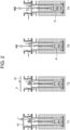
- FIGS 2 to 7 are schematic diagrams showing an example of a process of drawing the liquefied gas pump.
- the upper cover 51 of the buffer container 12 is removed from time T1 to T2, and the weight of the liquefied gas pump P is measured from time T3 to T5.
- gas for example, hydrogen
- gas supply pipe 52 communicating with the column 11.
- the liquefied gas in the column is pushed down, and the gas escapes from the region R of the foot valve provided at a lower part of the column 11.
- the liquefied gas inside the column 11 is discharged to the outside of the column.
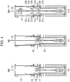
- the user attaches the purge container 13 on the buffer container 12, supplies gas (for example, nitrogen) through the gas supply pipe 54 communicating with the buffer container 12, and removes air in buffer container 12 and purge container 13.
- gas for example, nitrogen
- the user inserts his or her hands into the glove boxes 32a and 32b. Then, the user connects the hoist wire 18 to the sling wire 56 attached to the top plate 55 and winds the hoist wire 18 with the hoist drum 19 while observing the internal state through the work windows 33a and 33b. Thereby, the user lifts the top plate 55 as shown by the arrow. Then, at time T10, when the top plate 55 is lifted above the buffer lower plates 21a and 21b, the user inserts his or her hands from the glove boxes 32a and 32b, operates the winches 31a and 31b, and closes the buffer lower plates 21a and 21b.
- the user inserts his or her hands from the glove boxes 32a and 32b and positions the support wire 14 and the in-tank electric wire 15 while observing the internal state through the work windows 33a and 33b, so that the support wire 14 and the in-tank electric wire 15 are not pinched by the buffer lower plates 21a and 21b, and so that they pass through the opening 58.
- the user inserts his or her hands from the glove boxes 35a and 35b, operates the winches 34a and 34b, and closes the container lower plates 22a and 22b.
- the user inserts his or her hands from the glove boxes 35a and 35b and positions the support wire 14 and the in-tank electric wire 15 while observing the internal state through the work windows 36a and 36b, so that the support wire 14 and the in-tank electric wire 15 are not pinched by the container lower plates 22a and 22b, and so that they pass through the opening 58.
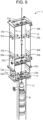
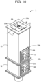
- glove boxes 37a, 37b and work windows 38a, 38b may be provided on the side walls of the purge container 13 below the container upper plates 23a and 23b.
- the user opens the container upper plates 23a and 23b to take out the top plate 55, and closes the container upper plates 23a and 23b.
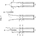
- the user removes the wire link 57. Then, at time T15, the user inserts his or her hands from the glove boxes 32a and 32b, operates the winches 31a and 31b and opens the buffer lower plates 21a and 21b, and inserts his or her hands from the glove boxes 35a and 35b, operates the winches 34a and 34b and opens the container lower plates 22a and 22b, to lift up the liquefied gas pump P.
- the user supplies a gas (for example, hydrogen) through a gas supply pipe 52 communicating with the column 11, and supplies a gas (for example, helium) through a gas supply pipe 54 communicating with the buffer container 12, to perform purging. This gas supply continues from time T15 to T18.
- a gas for example, hydrogen
- a gas for example, helium
- the user supplies a gas (for example, hydrogen) through a gas supply pipe 54 communicating with the purge container 13 to perform purging. Then, at time T18, the user opens the container upper plates 23a and 23b, and takes out the liquefied gas pump P. Thereafter, at time T19, the user closes the container upper plates 23a and 23b, and completes removal of the liquefied gas pump P.
- a gas for example, hydrogen
- sets of work windows and glove boxes near them are arranged at intervals in the up-down direction of the container.
- This allows the user to work while determining the positions of the hoist wire 18, support wire 14, in-tank electric wire 15, and liquefied gas pump P by: inserting his or her hands from the glove boxes 32a and 32b while observing the internal state from the work windows 33a and 33b; inserting his or her hands from the glove boxes 35a and 35b while observing the internal state from the work windows 36a and 36b; or inserting his or her hands from the glove boxes 37a and 37b while observing the internal state from the work windows 38a and 38b.
- This makes it possible to avoid contact of the inner wall surface from the hollow column 11 through the purge container 13 with these devices, and safely lift the devices such as the liquefied gas pump P.
- the user when performing maintenance on the liquefied gas pump P, the user can insert his or her hands from outside the purge container 13 into the glove boxes 35a and 35b inside the purge container 13, operate the winches 34a and 34b inside the purge container 13, and open and close container lower plates 22a and 22b provided at the lower part of the purge container 13.
- this configuration can prevent air from entering the barrier zone and the principal liquid from leaking outside from the partition chamber (purge container 13), due to insertion of human hands into the partition chamber (purge container 13).
- the user pulls up the liquefied gas pump P, support wire 14, and in-tank electric wire 15 through the long distance from the bottom of the hollow column 11 to above the purge container 13, the user pulls up the devices while observing the internal states through a plurality of work windows provided in the up-down direction of the container, inserting his or her hands from the glove boxes, and positioning the devices. This makes it possible to avoid contact of the inner wall surface from the hollow column 11 through the purge container 13 with these devices, and safely pull up the devices such as the liquefied gas pump P.
- the user when performing maintenance on the liquefied gas pump P, the user can insert his or her hands from outside the buffer container 12 into the glove boxes 32a and 32b inside the buffer container 12, operate the winches 31a and 31b inside the buffer container 12, and open and close the buffer lower plates 21a and 21b provided at the lower part of the buffer container 12.
- this configuration can prevent air from entering the barrier zone and the principal liquid from leaking outside from the partition chamber (buffer container 12), due to insertion of human hands into the partition chamber (buffer container 12).
- the user inserts his or her hands from the glove boxes 32a and 32b, and connects the hoist wire 18 to the sling wire 56 attached to the top plate 55 while observing the internal state from the work windows 33a and 33b.
- the length of a human hand is limited, and if the hand cannot reach the wires 18 and 56, there can be also a configuration such that: a pliers-like tool that can hold the hoist wire 18 on the sling wire 56 is provided on the inner wall of the buffer container 12; and the operator inserts his or her hands from the glove boxes 32a and 32b and uses such a work tool to hold the hoist wire 18 on the sling wire 56.
- the glove boxes 32a, 32b, 35a, and 35b may be movable glove boxes.
- the glove boxes 32a, 32b, 35a, and 35b includes fixed frames 39 each fixed to the side wall of the buffer container 12 and the purge container 13, a movable frame 41 attached to the fixed frame 39 so as to be movable inward via bellows 44, and a handle 40 provided so as to protrude outward from the movable frame 41.
- One end of the bellows 44 is fixed to the fixed frame 39 and the other end thereof is fixed to the movable frame 41.
- the buffer container 12 and the purge container 13 each have the inner side walls.
- Each side wall is provided with four guide shafts 42, which guide the movement of the movable frame 41, so as to protrude inward.
- Each movable frame 41 has four corners respectively provided with four bearings 43 that support the movable frame 41 so that it can slide along the guide shaft 42.
- the position and length of each guide shaft 42 is set at a location where it does not come into contact with the pump P passing inside the buffer container 12 and the purge container 13.
- each of the bearings 43 and the guide shafts 42 may be provided with a locking mechanism (not shown).
- the container according to the present invention has the advantage that the user does not need to open the container to insert human hands into the container in maintenance of the liquefied gas pump, and the container is usefully used in pump systems including liquefied gas pumps that deliver cryogenic liquefied gases such as liquefied hydrogen and liquefied ammonia.
Landscapes
- Engineering & Computer Science (AREA)
- Mechanical Engineering (AREA)
- General Engineering & Computer Science (AREA)
- Robotics (AREA)
- Filling Or Discharging Of Gas Storage Vessels (AREA)
- Manipulator (AREA)
Abstract
Description
- The present invention relates to a container, a pump system, and a maintenance method.
- Among liquefied gas pumps, conventional liquefied natural gas (LNG) pumps have had a temporary plate placed on a flange of the column top to prevent LNG from leaking to outside (for example, see Patent Literature 1). LNG is heavier than air in a low-temperature region, so it has never been released into the atmosphere. Contrarily, a cryogenic fluid such as liquefied hydrogen or liquefied ammonia has a specific gravity of the gasified gas lighter than that of air, so there is a risk that liquefied hydrogen or liquefied ammonia will be released.
- In a case of maintenance of liquefied hydrogen pumps, air (mainly oxygen and nitrogen) will liquefy and solidify in -253°C region when facing liquefied hydrogen. If air liquefies, liquid oxygen is produced that can be explosive, and when air solidifies, both the nitrogen and the oxygen can damage the pump. Furthermore, in a case of maintenance of liquefied ammonia pump, ammonia leakage outside can cause a health hazard to humans because ammonia is toxic.
- Patent Literature 1:
Japanese Patent Laid-Open No. 2018-80801 - When a user pulls up a cryogenic pump or installs a cryogenic pump in maintenance of a liquefied gas pump, a partition chamber is required, such as: a buffer container provided on a column around the liquefied gas pump and forming a barrier zone; or a purge container provided above the buffer container to avoid air from entering the inside and avoid the principal liquid (liquefied hydrogen, liquefied ammonia, etc.) from being released to the outside.
- Pulling up and installing a liquefied gas pump creates work to hold the pump in a partition chamber (for example, a purge container), and this work requires inevitably requires human hands. However, when the user opens the partition chamber to insert his or her hands into the partition chamber, there are problems in which air enters the barrier zone and the principal liquid leaks from the partition chamber to the outside.
- The present invention has been made in view of the above-mentioned problems, and it is an object thereof to provide a container, a pump system, and a maintenance method that do not require opening a container even in work with insertion of human hands into the container in maintenance of a liquefied gas pump.
- A container of the present invention is a hollow container provided above a hollow column provided around a liquefied gas pump, and the container includes: an openable and closable lower plate member provided at a lower part of the container; a manual opening/closing device provided inside the container and configured to be operated to open and close the lower plate member; a glove box provided inside the container and configured to allow a user to insert his or her hand from outside the container in order to operate the manual opening/closing device; and a work window arranged near the glove box and the manual opening/closing device so that the glove box and the manual opening/closing device are visible from outside the container.
- According to this configuration, when performing maintenance on the liquefied gas pump, the user can insert his or her hands from outside the container into the glove box inside the container (purge container), operate the manual opening/closing device inside the container, and open and close the lower plate member provided at a lower part of the container. In this case, when opening and closing the lower plate member of the container for maintenance of the liquefied gas pump, the user does not need to open the container to insert human hands into the container. Therefore, unlike the conventional configuration, this configuration can prevent air from entering the barrier zone and the principal liquid from leaking outside from the partition chamber (container), due to insertion of human hands into the partition chamber (purge container).
- The container of the present invention may further includes a buffer container arranged below the container and between the column and the container, in which the buffer container includes: a second openable and closable lower plate member provided at a lower part of the buffer container; a second manual opening/closing device provided inside the buffer container and configured to be operated to open and close the second lower plate member; a second glove box provided inside the buffer container and configured to allow a user to insert his or her hand from outside the buffer container in order to operate the second manual opening/closing device; and a second work window arranged near the second glove box and the second manual opening/closing device so that the second glove box and the second manual opening/closing device are visible from outside the buffer container.
- According to this configuration, when performing maintenance on the liquefied gas pump, the user can insert his or her hands from outside the buffer container into a second glove box inside the buffer container (arranged below the container and between the column and the container), operate the second manual opening/closing device inside the buffer container, and open and close the second lower plate member provided at a lower part of the buffer container. In this case, when opening and closing the second lower plate member of the buffer container for maintenance of the liquefied gas pump, the user does not need to open the buffer container to insert human hands into the buffer container. Therefore, unlike the conventional configuration, this configuration can prevent air from entering the barrier zone and the principal liquid from leaking outside from the partition chamber (buffer container), due to insertion of human hands into the partition chamber (buffer container).
- Furthermore, the container of the present invention may include the buffer container provided with: a third glove box configured to allow a user to insert his or her hands from outside the buffer container for manual work inside the buffer container; and a third work window arranged near the third glove box so that the inside of the buffer container is visible from the outside of the buffer container.
- According to this configuration, when performing maintenance on the liquefied gas pump, the user can insert his or her hands from outside the buffer container into a third glove box inside the buffer container to work inside the buffer container. In this case, when performing manual work inside the buffer container for maintenance of the liquefied gas pump, the user does not need to open the buffer container to insert human hands into the buffer container. Therefore, unlike the conventional configuration, this configuration can prevent air from entering the barrier zone and the principal liquid from leaking outside from the buffer container, due to insertion of human hands into the buffer container.
- The pump system of the present invention includes a liquefied gas pump and either of the containers described above.
- According to this system, like the container described above, when opening and closing the lower plate member of the container for maintenance of the liquefied gas pump, the user does not need to open the container to insert human hands into the container. Therefore, unlike the conventional configuration, this configuration can prevent air from entering the barrier zone and the principal liquid from leaking outside from the container, due to insertion of human hands into the purge container.
- A maintenance method of the present invention is a maintenance method for a liquefied gas pump, and the maintenance method includes: a step of providing a hollow container above a hollow column provided around the liquefied gas pump; and a step of a user inserting his or her hand from outside the container into a glove box provided inside the container, the user operating a manual opening/closing device provided inside the container, and the user opening and closing a lower plate member provided at a lower part of the container.
- According to this maintenance method, like the container described above, when opening and closing the lower plate member of the container for maintenance of the liquefied gas pump, the user does not need to open the container to insert human hands into the container. Therefore, unlike the conventional configuration, this configuration can prevent air from entering the barrier zone and the principal liquid from leaking outside from the container, due to insertion of human hands into the purge container.
- According to the present invention, in maintenance of the liquefied gas pump, the user does not need to open the container to insert human hands into the container.
-
- [
Figure 1] Figure 1 is an explanatory diagram showing a pump system in an embodiment of the present invention. - [
Figure 2] Figure 2 is an explanatory diagram showing an example of a process of drawing a liquefied gas pump in the embodiment of the present invention. - [
Figure 3] Figure 3 is an explanatory diagram showing an example of the process of drawing the liquefied gas pump in the embodiment of the present invention. - [
Figure 4] Figure 4 is an explanatory diagram showing an example of the process of drawing the liquefied gas pump in the embodiment of the present invention. - [
Figure 5] Figure 5 is an explanatory diagram showing an example of the process of drawing the liquefied gas pump in the embodiment of the present invention. - [
Figure 6] Figure 6 is an explanatory diagram showing an example of the process of drawing the liquefied gas pump in the embodiment of the present invention. - [
Figure 7] Figure 7 is an explanatory diagram showing an example of the process of drawing the liquefied gas pump in the embodiment of the present invention. - [
Figure 8] Figure 8 is an explanatory diagram showing another example of a purge container in the embodiment of the present invention. - [
Figure 9] Figure 9 is an explanatory diagram showing still another example of a purge container in the embodiment of the present invention. - [
Figure 10] Figure 10 is an explanatory diagram showing another example of a glove box in the embodiment of the present invention. - [
Figure 11] Figure 11 is an explanatory diagram showing still another example of a glove box in the embodiment of the present invention. - [
Figure 12] Figure 12 is an explanatory diagram showing still another example of a glove box in the embodiment of the present invention. - Hereinafter, a container according to an embodiment of the present invention will be described using the drawings. In the present embodiment, a case of a container will be illustrated that is used for a pump system, etc. including a liquefied gas pump that delivers cryogenic liquefied gas such as liquefied hydrogen or liquefied ammonia.
- A configuration of a pump system according to an embodiment of the present invention will be described with reference to the drawings.
Figure 1 is an explanatory diagram schematically showing a cross section of a pump system according to the present embodiment. As shown inFigure 1 , thepump system 1 includes a liquefied gas pump P. The liquefied gas pump P in one aspect is a pump for cryogenic liquefied gas, such as a liquid hydrogen pump or a liquefied ammonia pump. Furthermore, thepump system 1 includes ahollow column 11 provided around the liquefied gas pump P, ahollow buffer container 12 provided on top of thecolumn 11, and ahollow purge container 13 provided above thecolumn 11 and on top of thebuffer container 12. Here, thebuffer container 12 and thepurge container 13 are collectively referred to as containers, and the containers are hollow containers provided above a hollow column provided around the liquefied gas pump. - In this
pump system 1, thebuffer container 12 includes bufferlower plates buffer container 12 and can be opened and closed upward. Thepurge container 13 also includes containerlower plates purge container 13 and can be opened and closed upwards, and containerupper plates purge container 13 and can be opened and closed upwards. - When the buffer
lower plates lower plates upper plates buffer container 12 or within thepurge container 13. However, the bufferlower plates lower plates upper plates opening 58 near the vertical passage position of asupport wire 14 and an in-tankelectric wire 15 for allowing them (thesupport wire 14 and the in-tank electric wire 15) to pass even in the closed state. - The
pump system 1 also includes aconnector 24 connected to the liquefied gas pump P, asupport wire 14 connected to theconnector 24 for hanging and supporting the liquefied gas pump P, and a bisectedsupport members 16 provided on the containerupper plates pump system 1 also includes alifting link 17 provided on the bisectedsupport members 16, aconnector 25 connected to thesupport wire 14, ahoist wire 18 connected to theconnector 25, and ahoist drum 19 for winding uphoist wire 18. Note that thepump system 1 may or may not include the in-tank electric wire 15 connected to the liquefied gas pump P. - In this
pump system 1, thebuffer container 12 also includeswinches lower plates glove boxes buffer container 12 to operate thewinches work windows winches glove boxes winches glove boxes buffer container 12 are visible from the outside of thebuffer container 12 through thework windows - Furthermore, in this
pump system 1, thepurge container 13 includeswinches lower plates glove boxes purge container 13 to operate thewinches work windows winches glove boxes winches glove boxes purge container 13 are visible from the outside of thepurge container 13 through thework windows - The operation of the pump system configured as described above will be described with reference to the drawings.
-
Figures 2 to 7 are schematic diagrams showing an example of a process of drawing the liquefied gas pump. As shown inFigures 2 and3 , theupper cover 51 of thebuffer container 12 is removed from time T1 to T2, and the weight of the liquefied gas pump P is measured from time T3 to T5. Then, from time T6 to T7, gas (for example, hydrogen) is supplied through thegas supply pipe 52 communicating with thecolumn 11. As a result, the liquefied gas in the column is pushed down, and the gas escapes from the region R of the foot valve provided at a lower part of thecolumn 11. As a result, the liquefied gas inside thecolumn 11 is discharged to the outside of the column. - As shown in
Figures 4 and5 , at time T8, the user attaches thepurge container 13 on thebuffer container 12, supplies gas (for example, nitrogen) through thegas supply pipe 54 communicating with thebuffer container 12, and removes air inbuffer container 12 andpurge container 13. - At time T9, the user inserts his or her hands into the
glove boxes wire 18 to thesling wire 56 attached to thetop plate 55 and winds the hoistwire 18 with the hoistdrum 19 while observing the internal state through thework windows top plate 55 as shown by the arrow. Then, at time T10, when thetop plate 55 is lifted above the bufferlower plates glove boxes winches lower plates - At this time, when the buffer
lower plates glove boxes support wire 14 and the in-tank electric wire 15 while observing the internal state through thework windows support wire 14 and the in-tank electric wire 15 are not pinched by the bufferlower plates opening 58. - Furthermore, when the
top plate 55 is lifted above the containerlower plates glove boxes winches lower plates - At this time, when the container
lower plates glove boxes support wire 14 and the in-tank electric wire 15 while observing the internal state through thework windows support wire 14 and the in-tank electric wire 15 are not pinched by the containerlower plates opening 58. - In subsequent lifting of the
top plate 55 above thepurge container 13, if thetop plate 55 shakes within thepurge container 13, thetop plate 55 and thepurge container 13 may come into contact and be damaged. Then, in order to prevent thetop plate 55 from shaking inside thepurge container 13 and safely lift it upward, as shown inFigures 8 and9 ,glove boxes work windows purge container 13 below the containerupper plates - This allows the user to: observe the state of the hoist
wire 18, thesupport wire 14, the in-tank electric wire 15, andtop plate 55 from thework windows wire 18, thesupport wire 14, the in-tank electric wire 15, and thetop plate 55 by inserting his or her hands from theglove boxes top plate 55 above thepurge container 13 without shaking it. - From time T11 to T13, the user opens the container
upper plates top plate 55, and closes the containerupper plates - As shown in
Figures 6 and7 , at time T14, the user removes thewire link 57. Then, at time T15, the user inserts his or her hands from theglove boxes winches lower plates glove boxes winches lower plates gas supply pipe 52 communicating with thecolumn 11, and supplies a gas (for example, helium) through agas supply pipe 54 communicating with thebuffer container 12, to perform purging. This gas supply continues from time T15 to T18. - At time T16, when the liquefied gas pump P is lifted above the buffer
lower plates glove boxes winches lower plates lower plates glove boxes winches lower plates - At time T17, in a state in which the buffer
lower plates lower plates gas supply pipe 54 communicating with thepurge container 13 to perform purging. Then, at time T18, the user opens the containerupper plates upper plates - For the operations up to time T17, sets of work windows and glove boxes near them are arranged at intervals in the up-down direction of the container. This allows the user to work while determining the positions of the hoist
wire 18,support wire 14, in-tank electric wire 15, and liquefied gas pump P by: inserting his or her hands from theglove boxes work windows glove boxes work windows glove boxes work windows hollow column 11 through thepurge container 13 with these devices, and safely lift the devices such as the liquefied gas pump P. - According to the pump system of the present embodiment, when performing maintenance on the liquefied gas pump P, the user can insert his or her hands from outside the
purge container 13 into theglove boxes purge container 13, operate thewinches purge container 13, and open and close containerlower plates purge container 13. In this case, when opening and closing the containerlower plates purge container 13 for maintenance of the liquefied gas pump P, the user does not need to open thepurge container 13 to insert human hands into thepurge container 13. Therefore, unlike the conventional configuration, this configuration can prevent air from entering the barrier zone and the principal liquid from leaking outside from the partition chamber (purge container 13), due to insertion of human hands into the partition chamber (purge container 13). - Furthermore, while the user pulls up the liquefied gas pump P,
support wire 14, and in-tank electric wire 15 through the long distance from the bottom of thehollow column 11 to above thepurge container 13, the user pulls up the devices while observing the internal states through a plurality of work windows provided in the up-down direction of the container, inserting his or her hands from the glove boxes, and positioning the devices. This makes it possible to avoid contact of the inner wall surface from thehollow column 11 through thepurge container 13 with these devices, and safely pull up the devices such as the liquefied gas pump P. - Furthermore, according to the present embodiment, when performing maintenance on the liquefied gas pump P, the user can insert his or her hands from outside the
buffer container 12 into theglove boxes buffer container 12, operate thewinches buffer container 12, and open and close the bufferlower plates buffer container 12. In this case, when opening and closing the bufferlower plates buffer container 12 for maintenance of the liquefied gas pump P, the user does not need to open thebuffer container 12 to insert human hands into thebuffer container 12. Therefore, unlike the conventional configuration, this configuration can prevent air from entering the barrier zone and the principal liquid from leaking outside from the partition chamber (buffer container 12), due to insertion of human hands into the partition chamber (buffer container 12). - Although an embodiment of the present invention is described above by way of illustration, the scope of the present invention is not limited to this and can be changed and modified according to the purpose within the scope described in the claims.
- For example, at time T9, the user inserts his or her hands from the
glove boxes wire 18 to thesling wire 56 attached to thetop plate 55 while observing the internal state from thework windows wires wire 18 on thesling wire 56 is provided on the inner wall of thebuffer container 12; and the operator inserts his or her hands from theglove boxes wire 18 on thesling wire 56. - Furthermore, as shown in
Figures 10 to 12 , theglove boxes glove boxes frames 39 each fixed to the side wall of thebuffer container 12 and thepurge container 13, amovable frame 41 attached to the fixedframe 39 so as to be movable inward viabellows 44, and ahandle 40 provided so as to protrude outward from themovable frame 41. One end of thebellows 44 is fixed to the fixedframe 39 and the other end thereof is fixed to themovable frame 41. - In this case, as shown in
Figures 11 and12 , thebuffer container 12 and thepurge container 13 each have the inner side walls. Each side wall is provided with fourguide shafts 42, which guide the movement of themovable frame 41, so as to protrude inward. Eachmovable frame 41 has four corners respectively provided with fourbearings 43 that support themovable frame 41 so that it can slide along theguide shaft 42. The position and length of eachguide shaft 42 is set at a location where it does not come into contact with the pump P passing inside thebuffer container 12 and thepurge container 13. Furthermore, each of thebearings 43 and theguide shafts 42 may be provided with a locking mechanism (not shown). - Even in a
larger buffer container 12 and alarger purge container 13, employment of such a movable glove box allows the worker to move themovable frames 41 of theglove boxes frame 39 and themovable frame 41 are connected via the bellows 44. This makes it possible to prevent the liquefied gas inside thebuffer container 12 and thepurge container 13 from leaking to the outside, and to prevent external air from entering the inside of thebuffer container 12 and thepurge container 13 even if the operator moves themovable frame 41, allowing for safely working. - As described above, the container according to the present invention has the advantage that the user does not need to open the container to insert human hands into the container in maintenance of the liquefied gas pump, and the container is usefully used in pump systems including liquefied gas pumps that deliver cryogenic liquefied gases such as liquefied hydrogen and liquefied ammonia.
-
- 1 pump system
- 11 column
- 12 buffer container
- 13 purge container
- 14 support wire
- 15 in-tank electric wire
- 16 bisected support member
- 17 lifting link
- 18 hoist wire
- 19 hoist drum
- 21a, 21b buffer lower plate (second lower plate member)
- 22a, 22b container lower plate (lower plate member)
- 23a, 23b container upper plate
- 24 connector
- 25 connector
- 31a, 31b winch (second manual opening/closing device)
- 32a, 32b glove box (second glove box)
- 33a, 33b work window (second work window)
- 34a, 34b winch (manual opening/closing device)
- 35a, 35b glove box
- 36a, 36b work window
- 37a, 37b glove box
- 38a, 38b work window
- 39 fixed frame
- 40 handle
- 41 movable frame
- 42 guide shaft
- 43 bearing
- 44 bellows
- 51 upper cover
- 52 gas supply pipe
- 54 gas supply pipe
- 56 sling wire
- 57 wire link
- 58 opening
- P liquefied gas pump
- R region of foot valve
Claims (4)
- A container being a hollow container provided above a hollow column provided around a liquefied gas pump, the container comprising:an openable and closable lower plate member provided at a lower part of the container;a manual opening/closing device provided inside the container and configured to be operated to open and close the lower plate member;a glove box provided inside the container and configured to allow a user to insert his or her hand from outside the container in order to operate the manual opening/closing device; anda work window arranged near the glove box and the manual opening/closing device so that the glove box and the manual opening/closing device are visible from outside the container.
- The container according to claim 1, comprising a buffer container arranged below the container and between the column and the container, wherein
the buffer container includes:a second openable and closable lower plate member provided at a lower part of the buffer container;a second manual opening/closing device provided inside the buffer container and configured to be operated to open and close the second lower plate member;a second glove box provided inside the buffer container and configured to allow a user to insert his or her hand from outside the buffer container in order to operate the second manual opening/closing device; anda second work window arranged near the second glove box and the second manual opening/closing device so that the second glove box and the second manual opening/closing device are visible from outside the buffer container. - A pump system comprising:a liquefied gas pump; andthe container according to claim 1 or 2.
- A maintenance method for a liquefied gas pump, the maintenance method comprising:a step of providing a hollow container above a hollow column provided around the liquefied gas pump; anda step of a user inserting his or her hand from outside the container into a glove box provided inside the container, the user operating a manual opening/closing device provided inside the container, and the user opening and closing a lower plate member provided at a lower part of the container.
Applications Claiming Priority (2)
| Application Number | Priority Date | Filing Date | Title |
|---|---|---|---|
| JP2021207650 | 2021-12-22 | ||
| PCT/JP2022/047184 WO2023120591A1 (en) | 2021-12-22 | 2022-12-21 | Container, pump system, and maintenance method |
Publications (2)
| Publication Number | Publication Date |
|---|---|
| EP4455539A1 true EP4455539A1 (en) | 2024-10-30 |
| EP4455539A4 EP4455539A4 (en) | 2025-12-31 |
Family
ID=86902674
Family Applications (1)
| Application Number | Title | Priority Date | Filing Date |
|---|---|---|---|
| EP22911293.3A Pending EP4455539A4 (en) | 2021-12-22 | 2022-12-21 | CONTAINER, PUMP SYSTEM AND MAINTENANCE PROCEDURES |
Country Status (8)
| Country | Link |
|---|---|
| US (1) | US20250060075A1 (en) |
| EP (1) | EP4455539A4 (en) |
| JP (1) | JPWO2023120591A1 (en) |
| KR (1) | KR20240122812A (en) |
| CN (1) | CN118414524A (en) |
| AU (1) | AU2022421559A1 (en) |
| CA (1) | CA3242626A1 (en) |
| WO (1) | WO2023120591A1 (en) |
Family Cites Families (9)
| Publication number | Priority date | Publication date | Assignee | Title |
|---|---|---|---|---|
| DE3135426A1 (en) * | 1980-10-09 | 1982-06-24 | Deutsche Itt Industries Gmbh, 7800 Freiburg | FOLDABLE PUMP SYSTEM |
| JPS58183478A (en) * | 1982-04-06 | 1983-10-26 | ト−ヨ−カネツ株式会社 | Equipment for replacing tank accessories |
| JPH088400Y2 (en) * | 1990-11-08 | 1996-03-06 | 石川島播磨重工業株式会社 | Submerged pump loading / unloading device for underground tank |
| JPH0560299A (en) * | 1991-08-30 | 1993-03-09 | Ishikawajima Harima Heavy Ind Co Ltd | Cold tank valve repair device |
| FR2685244B1 (en) * | 1991-12-24 | 1994-03-11 | Matieres Nucleaires Cie Gle | GLOVE ASSEMBLY FOR A CONTAINMENT ENCLOSURE. |
| US5865605A (en) * | 1997-03-20 | 1999-02-02 | Chicago Bridge & Iron Company | Method and apparatus for removing a high pressure in-tank pump using a low pressure tube |
| JP6721983B2 (en) * | 2015-12-25 | 2020-07-15 | 株式会社Ihiプラント | Method for removing the contents inside the nozzle tube |
| JP6855219B2 (en) | 2016-11-18 | 2021-04-07 | 川崎重工業株式会社 | Insulated container for cryogenic gas pump |
| CN214747150U (en) * | 2021-01-29 | 2021-11-16 | 盐城市卓然自动化装备有限公司 | Heat accumulation type shaft kiln type vacuum calcining furnace |
-
2022
- 2022-12-21 AU AU2022421559A patent/AU2022421559A1/en active Pending
- 2022-12-21 CA CA3242626A patent/CA3242626A1/en active Pending
- 2022-12-21 JP JP2023569500A patent/JPWO2023120591A1/ja active Pending
- 2022-12-21 CN CN202280084298.1A patent/CN118414524A/en active Pending
- 2022-12-21 KR KR1020247022613A patent/KR20240122812A/en active Pending
- 2022-12-21 WO PCT/JP2022/047184 patent/WO2023120591A1/en not_active Ceased
- 2022-12-21 EP EP22911293.3A patent/EP4455539A4/en active Pending
- 2022-12-21 US US18/721,751 patent/US20250060075A1/en active Pending
Also Published As
| Publication number | Publication date |
|---|---|
| CA3242626A1 (en) | 2023-06-29 |
| EP4455539A4 (en) | 2025-12-31 |
| JPWO2023120591A1 (en) | 2023-06-29 |
| CN118414524A (en) | 2024-07-30 |
| US20250060075A1 (en) | 2025-02-20 |
| KR20240122812A (en) | 2024-08-13 |
| WO2023120591A1 (en) | 2023-06-29 |
| AU2022421559A1 (en) | 2024-07-04 |
Similar Documents
| Publication | Publication Date | Title |
|---|---|---|
| US10801370B2 (en) | Apparatus for handling a turbomachine part | |
| US10224123B2 (en) | Cask transport assembly | |
| US8411813B2 (en) | Method for carrying out reactor internal | |
| KR102087861B1 (en) | Apparatus for screwing on and off a bottle cap and chemical sampling apparatus including the same | |
| KR102101303B1 (en) | Apparatus for sampling chemical | |
| US20250060075A1 (en) | Container, pump system, and maintenance method | |
| KR102303098B1 (en) | Apparatus for screwing on and off a bottle cap and chemical sampling apparatus including the same | |
| CN102530670A (en) | Elevator device | |
| WO2023112979A1 (en) | Method for maintenance of send out pump in ammonia tank | |
| CN117881897A (en) | Lifting device, pump loading method, pump lifting method | |
| KR102151563B1 (en) | Apparatus for preventing outflow of chemical and chemical sampling apparatus having the same | |
| JP6340130B1 (en) | Manhole air duct installation device | |
| RU2399972C2 (en) | Container for unloading portable unit with active zone or without it | |
| JPH088400Y2 (en) | Submerged pump loading / unloading device for underground tank | |
| JPH0123392B2 (en) | ||
| KR102357647B1 (en) | Chemical sampling apparatus | |
| JP2011163880A (en) | Equipment and method for carrying in and out instrument | |
| EP2407977A1 (en) | Access area opening and closing device that opens to working platform of reactor vessel | |
| CN210923486U (en) | Chemical industry experiment test solution detection equipment | |
| US20240353068A1 (en) | Integrally-transportable purge container and method of using the integrally-transportable purge container | |
| JPS59219408A (en) | Temperature measuring and sampling device in vacuum refining furnace | |
| KR20230041076A (en) | phosgene production unit | |
| KR20240039136A (en) | Purge container and method of using the purge container | |
| JP2002019882A (en) | Material casting container | |
| JP2007002481A (en) | Manhole handrail |
Legal Events
| Date | Code | Title | Description |
|---|---|---|---|
| STAA | Information on the status of an ep patent application or granted ep patent |
Free format text: STATUS: THE INTERNATIONAL PUBLICATION HAS BEEN MADE |
|
| PUAI | Public reference made under article 153(3) epc to a published international application that has entered the european phase |
Free format text: ORIGINAL CODE: 0009012 |
|
| STAA | Information on the status of an ep patent application or granted ep patent |
Free format text: STATUS: REQUEST FOR EXAMINATION WAS MADE |
|
| 17P | Request for examination filed |
Effective date: 20240701 |
|
| AK | Designated contracting states |
Kind code of ref document: A1 Designated state(s): AL AT BE BG CH CY CZ DE DK EE ES FI FR GB GR HR HU IE IS IT LI LT LU LV MC ME MK MT NL NO PL PT RO RS SE SI SK SM TR |
|
| DAV | Request for validation of the european patent (deleted) | ||
| DAX | Request for extension of the european patent (deleted) | ||
| A4 | Supplementary search report drawn up and despatched |
Effective date: 20251201 |
|
| RIC1 | Information provided on ipc code assigned before grant |
Ipc: F17C 13/00 20060101AFI20251125BHEP Ipc: B25J 21/02 20060101ALI20251125BHEP Ipc: F04D 7/02 20060101ALI20251125BHEP Ipc: F04D 13/08 20060101ALI20251125BHEP Ipc: F04D 29/60 20060101ALI20251125BHEP Ipc: F17C 13/12 20060101ALI20251125BHEP |