EP4455519A1 - Multi-surface sealing for two-position valves - Google Patents
Multi-surface sealing for two-position valves Download PDFInfo
- Publication number
- EP4455519A1 EP4455519A1 EP24173062.1A EP24173062A EP4455519A1 EP 4455519 A1 EP4455519 A1 EP 4455519A1 EP 24173062 A EP24173062 A EP 24173062A EP 4455519 A1 EP4455519 A1 EP 4455519A1
- Authority
- EP
- European Patent Office
- Prior art keywords
- seal
- valve
- housing
- stroking
- face
- Prior art date
- Legal status (The legal status is an assumption and is not a legal conclusion. Google has not performed a legal analysis and makes no representation as to the accuracy of the status listed.)
- Granted
Links
Images



Classifications
-
- F—MECHANICAL ENGINEERING; LIGHTING; HEATING; WEAPONS; BLASTING
- F16—ENGINEERING ELEMENTS AND UNITS; GENERAL MEASURES FOR PRODUCING AND MAINTAINING EFFECTIVE FUNCTIONING OF MACHINES OR INSTALLATIONS; THERMAL INSULATION IN GENERAL
- F16K—VALVES; TAPS; COCKS; ACTUATING-FLOATS; DEVICES FOR VENTING OR AERATING
- F16K1/00—Lift valves or globe valves, i.e. cut-off apparatus with closure members having at least a component of their opening and closing motion perpendicular to the closing faces
- F16K1/32—Details
- F16K1/34—Cutting-off parts, e.g. valve members, seats
- F16K1/44—Details of seats or valve members of double-seat valves
- F16K1/443—Details of seats or valve members of double-seat valves the seats being in series
-
- F—MECHANICAL ENGINEERING; LIGHTING; HEATING; WEAPONS; BLASTING
- F16—ENGINEERING ELEMENTS AND UNITS; GENERAL MEASURES FOR PRODUCING AND MAINTAINING EFFECTIVE FUNCTIONING OF MACHINES OR INSTALLATIONS; THERMAL INSULATION IN GENERAL
- F16K—VALVES; TAPS; COCKS; ACTUATING-FLOATS; DEVICES FOR VENTING OR AERATING
- F16K1/00—Lift valves or globe valves, i.e. cut-off apparatus with closure members having at least a component of their opening and closing motion perpendicular to the closing faces
- F16K1/32—Details
- F16K1/34—Cutting-off parts, e.g. valve members, seats
- F16K1/44—Details of seats or valve members of double-seat valves
-
- F—MECHANICAL ENGINEERING; LIGHTING; HEATING; WEAPONS; BLASTING
- F16—ENGINEERING ELEMENTS AND UNITS; GENERAL MEASURES FOR PRODUCING AND MAINTAINING EFFECTIVE FUNCTIONING OF MACHINES OR INSTALLATIONS; THERMAL INSULATION IN GENERAL
- F16K—VALVES; TAPS; COCKS; ACTUATING-FLOATS; DEVICES FOR VENTING OR AERATING
- F16K1/00—Lift valves or globe valves, i.e. cut-off apparatus with closure members having at least a component of their opening and closing motion perpendicular to the closing faces
- F16K1/32—Details
- F16K1/34—Cutting-off parts, e.g. valve members, seats
- F16K1/46—Attachment of sealing rings
- F16K1/465—Attachment of sealing rings to the valve seats
-
- F—MECHANICAL ENGINEERING; LIGHTING; HEATING; WEAPONS; BLASTING
- F16—ENGINEERING ELEMENTS AND UNITS; GENERAL MEASURES FOR PRODUCING AND MAINTAINING EFFECTIVE FUNCTIONING OF MACHINES OR INSTALLATIONS; THERMAL INSULATION IN GENERAL
- F16K—VALVES; TAPS; COCKS; ACTUATING-FLOATS; DEVICES FOR VENTING OR AERATING
- F16K11/00—Multiple-way valves, e.g. mixing valves; Pipe fittings incorporating such valves
- F16K11/02—Multiple-way valves, e.g. mixing valves; Pipe fittings incorporating such valves with all movable sealing faces moving as one unit
- F16K11/04—Multiple-way valves, e.g. mixing valves; Pipe fittings incorporating such valves with all movable sealing faces moving as one unit comprising only lift valves
-
- F—MECHANICAL ENGINEERING; LIGHTING; HEATING; WEAPONS; BLASTING
- F16—ENGINEERING ELEMENTS AND UNITS; GENERAL MEASURES FOR PRODUCING AND MAINTAINING EFFECTIVE FUNCTIONING OF MACHINES OR INSTALLATIONS; THERMAL INSULATION IN GENERAL
- F16K—VALVES; TAPS; COCKS; ACTUATING-FLOATS; DEVICES FOR VENTING OR AERATING
- F16K27/00—Construction of housing; Use of materials therefor
- F16K27/02—Construction of housing; Use of materials therefor of lift valves
Definitions
- the present disclosure relates to valves, and more particularly to sealing in valves such as two-position valves.
- valves there is a need for valves to have multi-surface sealing where two or more locations on a valve are required to seal with the valve in a closed state.
- multiple tolerance stackups in all of the parts related to the multiple surface sealing system, it can be difficult to assure sealing without applying significant loads to assure all seal locations compress and fully seal.
- One solution is to utilize very tight tolerances, however this can add considerable cost of manufacturing.
- a valve includes a housing.
- a stroking valve is operatively connected to the housing for valve stroking movement relative to the housing in a direction of a longitudinal axis of the housing.
- the stroking valve has an open position for flow through the housing and a closed position for blocking flow through the housing.
- a first biasing member is operatively connected between the housing and the stroking valve, biasing the stroking valve in a first direction toward the closed position.
- a seal block is operatively connected to the housing for stroking movement relative to the housing in the direction of the longitudinal axis.
- a second biasing member is operatively connected between the housing and the seal block, biasing the seal block in a second direction opposite the first direction.
- a first face seal is positioned to seal between the stroking valve and the housing with the stroking valve in the closed position.
- a second face seal is positioned to seal between the stroking valve and the seal block.
- the stroking valve is configured to make sealing contact with the second face seal between the seal block and the stroking valve after a first portion of a stroke from the open position to the closed position prior to making sealing contact with the first face seal between the stroking valve and the housing.
- the first face seal can be seated in a face seal channel in the stroking valve.
- the face seal channel in the stroking valve can open toward a face sealing surface of the housing.
- the second face seal can be seated in a face seal channel in the seal block.
- the face seal channel in the seal block can open toward a face sealing surface of the stroking valve.
- a first radial seal can seal between the housing and the seal block.
- the first radial seal can be seated in a radial seal channel in the seal block.
- the radial seal channel in the seal block can open toward a first radial facing seal face of the housing.
- a second radial seal can seal between the housing and the stroking valve.
- the second radial seal can be seated in a radial seal channel in the stroking valve.
- the radial seal channel in the stroking valve can open toward a second radial facing seal face of the housing.
- a first volume of the housing can be separated from a second volume of the housing by a drip tight seal at each of the first face seal, the second face seal, the first radial seal, and the second radial seal.
- the first biasing member can include a coiled spring that is in compression in the open position of the stroking valve.
- the second biasing member can include a disc spring in constant compression with the stroking valve in the first portion of the stroke and in increasing compression with the stroking valve between the first portion of the stroke and the closed position.
- a retainer can be fixed relative to the housing.
- the second biasing member can be seated between the seal bock and the retainer in an axial direction.
- the stroking valve can be configured return from the closed position to the open position, first breaking sealing contact with of the first face seal then breaking sealing contact with the second face seal.
- FIG. 1 a partial view of an embodiment of a valve in accordance with the disclosure is shown in Fig. 1 and is designated generally by reference character 100.
- FIGs. 2-5 Other embodiments of systems in accordance with the disclosure, or aspects thereof, are provided in Figs. 2-5 , as will be described.
- the systems and methods described herein can be used to provide two-surface sealing in valves with reduced tolerancing and/or reduced loading on the seals relative to traditional multi-surface sealing arrangements.
- the valve 100 includes a housing 102, three portions of which are shown in Fig. 1 .
- the longitudinal axis A of the valve is shown in Fig. 1 , e.g. as a centerline about which the geometry of the valve 100 is cylindrically defined.
- a stroking valve 104 is operatively connected to the housing 102 for valve stroking movement relative to the housing 102 in a direction of the longitudinal axis A.
- the stroking valve 104 has an open position shown in Fig. 1 for flow through the housing 102 (as indicated by the flow arrows in Fig. 1 ) and a closed position, shown in Fig. 3 , for blocking flow through the housing 102.
- a first biasing member 106 e.g. a coiled spring or other suitable resilient body, is operatively connected between the housing 102 and the stroking valve 104, biasing the stroking valve 104 in a first direction, i.e. downward as oriented in Fig. 1 , toward the closed position shown in Fig. 2 .
- the first biasing member 106 is in compression in the open position of the stroking valve 104 as shown in Fig. 1 .
- a seal block 108 is operatively connected to the housing 102 for stroking movement relative to the housing 102 in the direction of the longitudinal axis A.
- a second biasing member 110 e.g. a relatively thin, light disc spring, Belleville washer, or other suitable resilient body, is operatively connected between the housing 102 and the seal block 108, biasing the seal block 108 in a second direction opposite the first direction, i.e. the second spring biases the seal block 108 in the upward direction as oriented in Fig. 1 .
- the second biasing member 110 is in constant compression with the stroking valve 104 in the first portion of the stroke, i.e. in the position in Fig. 1 and every position between there and the position shown in Fig. 2 .
- the second biasing member 110 is in increasing compression with the stroking valve 104 moving between the position shown in Fig. 2 and the closed position shown in Fig. 3 .
- a retainer 138 is fixed relative to the housing 102.
- the second biasing member 110 is seated between the seal bock 108 and the retainer 110 in an axial direction, i.e. in the direction along the longitudinal axis A.
- a first face seal 112 is positioned to seal between the stroking valve 104 and the housing 102 with the stroking valve in the closed position as shown in Fig. 3 .
- a second face seal 114 is positioned to seal between the stroking valve 104 and the seal block 108.
- the stroking valve 104 is configured to make sealing contact with the second face seal 114 between the seal block 108 and the stroking valve 104 after a first portion of a stroke, i.e. at the position shown in Fig. 2 , from the open position of Fig. 1 to the closed position of Fig. 3 , prior to making sealing contact with the first face seal 112 between the stroking valve 104 and the housing 102.
- the second biasing member 110 accommodates movement of the seal block and stroking valve 104 past the first portion of the stroke, i.e. as the stroking valve 104 continues to move past the position in Fig. 2 to the closed position in Fig. 3 .
- the first face seal 112 is seated in a face seal channel 116 in the stroking valve 104.
- the face seal channel 116 opens toward a face sealing surface 118 of the housing 102.
- the second face seal 114 is seated in a face seal channel 120 in the seal block 108.
- the face seal channel 120 opens toward a face sealing surface 122 of the stroking valve 104.
- a first radial seal 124 seals between the housing 102 and the seal block 108.
- the first radial seal 124 is seated in a radial seal channel 126 in the seal block 108.
- the radial seal channel 126 opens toward a first radial facing seal face 128 of the housing 102.
- a second radial seal 130 seals between the housing 102 and the stroking valve 104.
- the second radial seal 130 is seated in a radial seal channel 132 in the stroking valve 104.
- the radial seal channel 132 opens toward a second radial facing seal face 134 of the housing 104.
- the radial facing seal face 134 includes a ramp step 136 configured to slightly relieve seal load while still sealing for the stroking valve 104 to approach the closed position of Fig. 3 beyond the first portion of the stroke, i.e. below the position shown in Fig. 2 .
- a first volume 140 of the housing 102 is separated from a second volume 142 of the housing 104 by a drip tight seal at each of the first face seal 112, the second face seal 114, the first radial seal 124, and the second radial seal 130.
- the stroking valve 104 is configured return from the closed position shown in Fig. 3 to the open position shown in Fig. 1 , first breaking sealing contact with of the first face seal 112 then breaking sealing contact with the second face seal 114 after passing back through the position shown in Fig. 2 .
- Each of the face seal channel 116, the face seal channel 120, the radial seal channel 126, the radial seal channel 132, the face sealing surface 118, the face sealing surface 122, the first radial facing seal face 128, and the second radial facing seal face 134 need be made within no tighter than standard tolerances, e.g. of the range of +/- .002 inches, (.05 mm) to +/- .005 inches, (.127 mm).
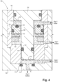
- FIG. 4 another embodiment of the valve 100 is shown, wherein there are two fluid flow paths, labeled Fluid 1 and Fluid 2, through the valve 100.
- the seal 112 and its gland 115 are located in the stationary housing 102, rather than in the stroking valve 104.
- the sealing surface 118 is on the stroking valve 104, rather than on the housing 102, which is reversed from the embodiment of Figs. 1-3 .
- Fig. 5 shows the closed position of the valve 100, which shuts off flow for both fluids, Fluid 1 and Fluid 2.
- Systems and methods as disclosed herein provide potential benefits including the following. More traditional configurations to utilize a large heavy spring to accommodate all of the tolerances and assure drop tight seal.
- a relatively low load spring can be used to assure sealing on the two face seal locations. This approach can result in the ability to achieve drop tight seal on two surfaces, utilizing standard traditional tolerances used for single surface sealing, and low spring force in the two-position valve while saving weight and improving manufacturability and field reliability of the seals. It should be noted that while a two surface seal system is described, the approach is valid for multiple sealing surfaces greater than two with all but the first sealing surface having sliding block seals system as described.
Landscapes
- Engineering & Computer Science (AREA)
- General Engineering & Computer Science (AREA)
- Mechanical Engineering (AREA)
- Lift Valve (AREA)
Abstract
Description
- The present disclosure relates to valves, and more particularly to sealing in valves such as two-position valves.
- There is a need for valves to have multi-surface sealing where two or more locations on a valve are required to seal with the valve in a closed state. With multiple tolerance stackups in all of the parts related to the multiple surface sealing system, it can be difficult to assure sealing without applying
significant loads to assure all seal locations compress and fully seal. One solution is to utilize very tight tolerances, however this can add considerable cost of manufacturing. - The conventional techniques have been considered satisfactory for their intended purpose. However, there is an ever present need for improved systems and methods for sealing multiple surfaces in valves such as two-position valves. This disclosure provides a solution for this need.
- A valve includes a housing. A stroking valve is operatively connected to the housing for valve stroking movement relative to the housing in a direction of a longitudinal axis of the housing. The stroking valve has an open position for flow through the housing and a closed position for blocking flow through the housing. A first biasing member is operatively connected between the housing and the stroking valve, biasing the stroking valve in a first direction toward the closed position. A seal block is operatively connected to the housing for stroking movement relative to the housing in the direction of the longitudinal axis. A second biasing member is operatively connected between the housing and the seal block, biasing the seal block in a second direction opposite the first direction. A first face seal is positioned to seal between the stroking valve and the housing with the stroking valve in the closed position. A second face seal is positioned to seal between the stroking valve and the seal block. The stroking valve is configured to make sealing contact with the second face seal between the seal block and the stroking valve after a first portion of a stroke from the open position to the closed position prior to making sealing contact with the first face seal between the stroking valve and the housing.
- The first face seal can be seated in a face seal channel in the stroking valve. The face seal channel in the stroking valve can open toward a face sealing surface of the housing. The second face seal can be seated in a face seal channel in the seal block. The face seal channel in the seal block can open toward a face sealing surface of the stroking valve.
- A first radial seal can seal between the housing and the seal block. The first radial seal can be seated in a radial seal channel in the seal block. The radial seal channel in the seal block can open toward a first radial facing seal face of the housing. A second radial seal can seal between the housing and the stroking valve. The second radial seal can be seated in a radial seal channel in the stroking valve. The radial seal channel in the stroking valve can open toward a second radial facing seal face of the housing.
- With the stroking valve in the closed position, a first volume of the housing can be separated from a second volume of the housing by a drip tight seal at each of the first face seal, the second face seal, the first radial seal, and the second radial seal. Each of
- the face seal channel in the stroking valve,
- the face seal channel in the seal block,
- the radial seal channel in the seal block,
- the radial seal channel in the stroking valve,
- the face sealing surface of the housing,
- the face sealing surface of the stroking valve,
- the first radial facing seal face of the housing, and
- the second radial facing seal face of the housing
- The first biasing member can include a coiled spring that is in compression in the open position of the stroking valve. The second biasing member can include a disc spring in constant compression with the stroking valve in the first portion of the stroke and in increasing compression with the stroking valve between the first portion of the stroke and the closed position. A retainer can be fixed relative to the housing. The second biasing member can be seated between the seal bock and the retainer in an axial direction. The stroking valve can be configured return from the closed position to the open position, first breaking sealing contact with of the first face seal then breaking sealing contact with the second face seal.
- These and other features of the systems and methods of the subject disclosure will become more readily apparent to those skilled in the art from the following detailed description of the preferred embodiments taken in conjunction with the drawings.
- So that those skilled in the art to which the subject disclosure appertains will readily understand how to make and use the devices and methods of the subject disclosure without undue experimentation, preferred embodiments thereof will be described in detail herein below with reference to certain figures, wherein:
-
Fig. 1 is a cross-sectional view of an embodiment of a valve constructed in accordance with the present disclosure, showing the housing and stroking valve with the stroking valve in the open position; -
Fig. 2 is a cross-sectional view of the valve ofFig. 1 , showing the position of the stroking valve after a first portion of the stroke where the first face seal makes contact; -
Fig. 3 is a cross-sectional view of the valve ofFig. 2 , showing the closed position of the stroking valve and a seal block, which holds the first seal ofFig. 2 ; -
Fig. 4 is a cross-sectional view of another embodiment of a valve constructed in accordance with the present disclosure, showing two separate fluid flows through the valve in the open position; and -
Fig. 5 is a cross-sectional view of the valve ofFig. 4 , showing flow blocked for both fluid flows. - Reference will now be made to the drawings wherein like reference numerals identify similar structural features or aspects of the subject disclosure. For purposes of explanation and illustration, and not limitation, a partial view of an embodiment of a valve in accordance with the disclosure is shown in
Fig. 1 and is designated generally byreference character 100. Other embodiments of systems in accordance with the disclosure, or aspects thereof, are provided inFigs. 2-5 , as will be described. The systems and methods described herein can be used to provide two-surface sealing in valves with reduced tolerancing and/or reduced loading on the seals relative to traditional multi-surface sealing arrangements. - The
valve 100 includes ahousing 102, three portions of which are shown inFig. 1 . The longitudinal axis A of the valve is shown inFig. 1 , e.g. as a centerline about which the geometry of thevalve 100 is cylindrically defined. Astroking valve 104 is operatively connected to thehousing 102 for valve stroking movement relative to thehousing 102 in a direction of the longitudinal axis A. The strokingvalve 104 has an open position shown inFig. 1 for flow through the housing 102 (as indicated by the flow arrows inFig. 1 ) and a closed position, shown inFig. 3 , for blocking flow through thehousing 102. - A
first biasing member 106, e.g. a coiled spring or other suitable resilient body, is operatively connected between thehousing 102 and the strokingvalve 104, biasing the strokingvalve 104 in a first direction, i.e. downward as oriented inFig. 1 , toward the closed position shown inFig. 2 . Thefirst biasing member 106 is in compression in the open position of the strokingvalve 104 as shown inFig. 1 . - A
seal block 108 is operatively connected to thehousing 102 for stroking movement relative to thehousing 102 in the direction of the longitudinal axis A. Asecond biasing member 110, e.g. a relatively thin, light disc spring, Belleville washer, or other suitable resilient body, is operatively connected between thehousing 102 and theseal block 108, biasing theseal block 108 in a second direction opposite the first direction, i.e. the second spring biases theseal block 108 in the upward direction as oriented inFig. 1 . Thesecond biasing member 110 is in constant compression with the strokingvalve 104 in the first portion of the stroke, i.e. in the position inFig. 1 and every position between there and the position shown inFig. 2 . Below the position of the strokingvalve 104 shown and as oriented inFig. 2 , thesecond biasing member 110 is in increasing compression with the strokingvalve 104 moving between the position shown inFig. 2 and the closed position shown inFig. 3 . Aretainer 138 is fixed relative to thehousing 102. Thesecond biasing member 110 is seated between theseal bock 108 and theretainer 110 in an axial direction, i.e. in the direction along the longitudinal axis A. - A
first face seal 112 is positioned to seal between the strokingvalve 104 and thehousing 102 with the stroking valve in the closed position as shown inFig. 3 . Asecond face seal 114 is positioned to seal between the strokingvalve 104 and theseal block 108. The strokingvalve 104 is configured to make sealing contact with thesecond face seal 114 between theseal block 108 and the strokingvalve 104 after a first portion of a stroke, i.e. at the position shown inFig. 2 , from the open position ofFig. 1 to the closed position ofFig. 3 , prior to making sealing contact with thefirst face seal 112 between the strokingvalve 104 and thehousing 102. Thesecond biasing member 110 accommodates movement of the seal block and strokingvalve 104 past the first portion of the stroke, i.e. as the strokingvalve 104 continues to move past the position inFig. 2 to the closed position inFig. 3 . - The
first face seal 112 is seated in aface seal channel 116 in the strokingvalve 104. Theface seal channel 116 opens toward aface sealing surface 118 of thehousing 102. Thesecond face seal 114 is seated in aface seal channel 120 in theseal block 108. Theface seal channel 120 opens toward aface sealing surface 122 of the strokingvalve 104. - A first
radial seal 124 seals between thehousing 102 and theseal block 108. The firstradial seal 124 is seated in aradial seal channel 126 in theseal block 108. Theradial seal channel 126 opens toward a first radial facingseal face 128 of thehousing 102. A secondradial seal 130 seals between thehousing 102 and the strokingvalve 104. The secondradial seal 130 is seated in aradial seal channel 132 in the strokingvalve 104. Theradial seal channel 132 opens toward a second radial facingseal face 134 of thehousing 104. The radial facingseal face 134 includes aramp step 136 configured to slightly relieve seal load while still sealing for the strokingvalve 104 to approach the closed position ofFig. 3 beyond the first portion of the stroke, i.e. below the position shown inFig. 2 . - With the stroking
valve 104 in the closed position shown inFig. 3 , afirst volume 140 of thehousing 102 is separated from asecond volume 142 of thehousing 104 by a drip tight seal at each of thefirst face seal 112, thesecond face seal 114, the firstradial seal 124, and the secondradial seal 130. The strokingvalve 104 is configured return from the closed position shown inFig. 3 to the open position shown inFig. 1 , first breaking sealing contact with of thefirst face seal 112 then breaking sealing contact with thesecond face seal 114 after passing back through the position shown inFig. 2 . - Each of the
face seal channel 116, theface seal channel 120, theradial seal channel 126, theradial seal channel 132, theface sealing surface 118, theface sealing surface 122, the first radial facingseal face 128, and the second radial facingseal face 134 need be made within no tighter than standard tolerances, e.g. of the range of +/- .002 inches, (.05 mm) to +/- .005 inches, (.127 mm). - With reference now to
Fig. 4 , another embodiment of thevalve 100 is shown, wherein there are two fluid flow paths, labeledFluid 1 andFluid 2, through thevalve 100. Like reference numerals are used inFig. 4 as toFig. 1 above, and the description and operation of like numbered elements are the same. One variation is that theseal 112 and its gland 115 are located in thestationary housing 102, rather than in the strokingvalve 104. The sealingsurface 118 is on the strokingvalve 104, rather than on thehousing 102, which is reversed from the embodiment ofFigs. 1-3 .Fig. 5 shows the closed position of thevalve 100, which shuts off flow for both fluids,Fluid 1 andFluid 2. - Systems and methods as disclosed herein provide potential benefits including the following. More traditional configurations to utilize a large heavy spring to accommodate all of the tolerances and assure drop tight seal. In accordance with the present disclosure, a relatively low load spring can be used to assure sealing on the two face seal locations. This approach can result in the ability to achieve drop tight seal on two surfaces, utilizing standard traditional tolerances used for single surface sealing, and low spring force in the two-position valve while saving weight and improving manufacturability and field reliability of the seals. It should be noted that while a two surface seal system is described, the approach is valid for multiple sealing surfaces greater than two with all but the first sealing surface having sliding block seals system as described.
- The methods and systems of the present disclosure, as described above and shown in the drawings, provide for two-surface sealing in valves with reduced tolerancing and/or reduced loading on the seals relative to traditional multi-surface sealing arrangements. While the apparatus and methods of the subject disclosure have been shown and described with reference to preferred embodiments, those skilled in the art will readily appreciate that changes and/or modifications may be made thereto without departing from the scope of the invention as defined by the claims.
Claims (15)
- A valve comprising:a housing (102);a stroking valve (104) operatively connected to the housing for valve stroking movement relative to the housing in a direction of a longitudinal axis of the housing, wherein the stroking valve has an open position for flow through the housing and a closed position for blocking flow through the housing;a first biasing member (106) operatively connected between the housing and the stroking valve, biasing the stroking valve in a first direction toward the closed position;a seal block (108) operatively connected to the housing for stroking movement relative to the housing in the direction of the longitudinal axis;a second biasing member (110) operatively connected between the housing and the seal block, biasing the seal block in a second direction opposite the first direction;a first face seal (112) positioned to seal between the stroking valve and the housing with the stroking valve in the closed position; anda second face seal (114) positioned to seal between the stroking valve and the seal block,wherein the stroking valve is configured to make sealing contact with the second face seal between the seal block and the stroking valve after a first portion of a stroke from the open position to the closed position prior to making sealing contact with the first face seal between the stroking valve and the housing.
- The valve as recited in claim 1, wherein the first face seal is seated in a face seal channel (116) in the stroking valve, wherein the face seal channel in the stroking valve opens toward a face sealing surface of the housing.
- The valve as recited in claim 2, wherein the second face seal is seated in a face seal channel (120) in the seal block, wherein the face seal channel in the seal block opens toward a face sealing surface of the stroking valve.
- The valve as recited in claim 3, further comprising a radial seal (124) sealing between the housing and the seal block.
- The valve seal as recited in claim 4, wherein the radial seal is seated in a radial seal channel (126) in the seal block, wherein the radial seal channel in the seal block opens toward a radial facing seal face of the housing.
- The valve seal as recited in claim 3, further comprising a radial seal (130) sealing between the housing and the stroking valve.
- The valve seal as recited in claim 6, wherein the radial seal is seated in a radial seal channel (132) in the stroking valve, wherein the radial seal channel in the stroking valve opens toward a radial facing seal face of the housing.
- The valve seal as recited in claim 7, wherein the radial facing seal face of the housing includes a ramp step (136) configured to relieve load while sealing for the stroking valve to approach the closed position beyond the first portion of the stroke.
- The valve as recited in claim 3, further comprising:a first radial seal (124) sealing between the housing and the seal block, wherein the first radial seal is seated in a radial seal channel (126) in the seal block, wherein the radial seal channel in the seal block opens toward a first radial facing seal face of the housing; anda second radial seal (130) sealing between the housing and the stroking valve, wherein the second radial seal is seated in a radial seal channel (132) in the stroking valve, wherein the radial seal channel in the stroking valve opens toward a second radial facing seal face of the housing.
- The valve seal as recited in claim 9, wherein with the stroking valve in the closed position, a first volume (140) of the housing is separated from a second volume (142) of the housing by a drip tight seal at each of the first face seal, the second face seal, the first radial seal, and the second radial seal.
- The valve seal as recited in claim 9, wherein each ofthe face seal channel in the stroking valve,the face seal channel in the seal block,the radial seal channel in the seal block,the radial seal channel in the stroking valve,the face sealing surface of the housing,the face sealing surface of the stroking valve,the first radial facing seal face of the housing, andthe second radial facing seal face of the housingare all within no tighter than standard tolerances.
- The valve as recited in any preceding claim, wherein the first biasing member (106) includes a coiled spring that is in compression in the open position of the stroking valve.
- The valve as recited in any preceding claim, wherein the second biasing member (110) includes a disc spring in constant compression with the stroking valve in the first portion of the stroke and in increasing compression with the stroking valve between the first portion of the stroke and the closed position.
- The valve as recited in any preceding claim, Further comprising a retainer (138) fixed relative to the housing, wherein the second biasing member is seated between the seal bock and the retainer in an axial direction.
- The valve as recited in any preceding claim, wherein the stroking valve is configured return from the closed position to the open position, first breaking sealing contact with of the first face seal then breaking sealing contact with the second face seal.
Applications Claiming Priority (1)
| Application Number | Priority Date | Filing Date | Title |
|---|---|---|---|
| US18/140,761 US12163593B2 (en) | 2023-04-28 | 2023-04-28 | Multi-surface sealing for two-position valves |
Publications (2)
| Publication Number | Publication Date |
|---|---|
| EP4455519A1 true EP4455519A1 (en) | 2024-10-30 |
| EP4455519B1 EP4455519B1 (en) | 2025-10-22 |
Family
ID=90924193
Family Applications (1)
| Application Number | Title | Priority Date | Filing Date |
|---|---|---|---|
| EP24173062.1A Active EP4455519B1 (en) | 2023-04-28 | 2024-04-29 | Multi-surface sealing for two-position valves |
Country Status (2)
| Country | Link |
|---|---|
| US (1) | US12163593B2 (en) |
| EP (1) | EP4455519B1 (en) |
Citations (1)
| Publication number | Priority date | Publication date | Assignee | Title |
|---|---|---|---|---|
| US9354638B2 (en) * | 2014-03-27 | 2016-05-31 | Emerson Process Management Regulator Technologies, Inc. | Double port pressure regulator with floating seat |
Family Cites Families (6)
| Publication number | Priority date | Publication date | Assignee | Title |
|---|---|---|---|---|
| DE3034056A1 (en) * | 1980-09-10 | 1982-04-15 | Hydrometer Gmbh, 8800 Ansbach | Combination meter changeover valve - reduces deposit formation using strong main flow choking during final valve closure stages |
| US4444214A (en) | 1981-05-18 | 1984-04-24 | Continental Disc Corporation | Replaceable rupture disc cartridge arrangement |
| US4995589A (en) | 1990-01-29 | 1991-02-26 | Sequioa Controls Company, Ltd. | Bellows valve |
| JP2007524050A (en) * | 2004-02-27 | 2007-08-23 | デーナ、カナダ、コーパレイシャン | Leakage resistant solenoid valve |
| US9140369B2 (en) | 2013-10-15 | 2015-09-22 | Fisher Controls International Llc | Floating ball valve seal |
| US11193427B2 (en) | 2018-04-27 | 2021-12-07 | Hamilton Sundstrand Corporation | Passive active poppet-type bleed valves |
-
2023
- 2023-04-28 US US18/140,761 patent/US12163593B2/en active Active
-
2024
- 2024-04-29 EP EP24173062.1A patent/EP4455519B1/en active Active
Patent Citations (1)
| Publication number | Priority date | Publication date | Assignee | Title |
|---|---|---|---|---|
| US9354638B2 (en) * | 2014-03-27 | 2016-05-31 | Emerson Process Management Regulator Technologies, Inc. | Double port pressure regulator with floating seat |
Also Published As
| Publication number | Publication date |
|---|---|
| EP4455519B1 (en) | 2025-10-22 |
| US20240360903A1 (en) | 2024-10-31 |
| US12163593B2 (en) | 2024-12-10 |
Similar Documents
| Publication | Publication Date | Title |
|---|---|---|
| CN112005033B (en) | Valve seat, valve assembly and related methods | |
| US4026322A (en) | Reciprocating pump check valve assembly | |
| US8490945B2 (en) | Valve sealing arrangements and methods | |
| EP2425158B1 (en) | Valve with bidirectional seal assembly | |
| US4471943A (en) | Valve assembly and seat | |
| US6345805B1 (en) | Rotary valve with seat assembly | |
| US3078865A (en) | Self sealing gate valve | |
| US4625942A (en) | Valve assembly, seat and seal | |
| US11867304B2 (en) | Valve assemblies, valve seats including flexible arms, and related methods | |
| EP2006586A2 (en) | Dynamic ball valve sealing device for three-way valves | |
| US6497226B2 (en) | Modular, compliant, sealing bearing assembly | |
| US7559531B2 (en) | Low torque ball valve with dynamic sealing | |
| KR20070032821A (en) | Ball valve seat structure | |
| US5755446A (en) | Seal apparatus between a shaft and a non-linear inner surface of a housing | |
| US9404513B2 (en) | Servo valve | |
| EP0701079B1 (en) | Expanding gate valve | |
| US5326077A (en) | Butterfly valve seal retainer | |
| US12467541B2 (en) | Seal assemblies and related valves and methods | |
| EP4455519B1 (en) | Multi-surface sealing for two-position valves | |
| USRE29299E (en) | Self sealing gate valve | |
| US4172470A (en) | Soft seat valve | |
| US5522422A (en) | Hydraulic pressure reducing valve | |
| KR850006597A (en) | Poppet valve assembly | |
| US9046098B2 (en) | Face sealing annular valve for a fluid-working machine | |
| US6588763B1 (en) | Seal arrangement providing a seal between a bore and a rod moveable in the bore |
Legal Events
| Date | Code | Title | Description |
|---|---|---|---|
| PUAI | Public reference made under article 153(3) epc to a published international application that has entered the european phase |
Free format text: ORIGINAL CODE: 0009012 |
|
| STAA | Information on the status of an ep patent application or granted ep patent |
Free format text: STATUS: THE APPLICATION HAS BEEN PUBLISHED |
|
| AK | Designated contracting states |
Kind code of ref document: A1 Designated state(s): AL AT BE BG CH CY CZ DE DK EE ES FI FR GB GR HR HU IE IS IT LI LT LU LV MC ME MK MT NL NO PL PT RO RS SE SI SK SM TR |
|
| STAA | Information on the status of an ep patent application or granted ep patent |
Free format text: STATUS: REQUEST FOR EXAMINATION WAS MADE |
|
| 17P | Request for examination filed |
Effective date: 20250429 |
|
| GRAP | Despatch of communication of intention to grant a patent |
Free format text: ORIGINAL CODE: EPIDOSNIGR1 |
|
| STAA | Information on the status of an ep patent application or granted ep patent |
Free format text: STATUS: GRANT OF PATENT IS INTENDED |
|
| INTG | Intention to grant announced |
Effective date: 20250611 |
|
| GRAS | Grant fee paid |
Free format text: ORIGINAL CODE: EPIDOSNIGR3 |
|
| GRAA | (expected) grant |
Free format text: ORIGINAL CODE: 0009210 |
|
| STAA | Information on the status of an ep patent application or granted ep patent |
Free format text: STATUS: THE PATENT HAS BEEN GRANTED |
|
| AK | Designated contracting states |
Kind code of ref document: B1 Designated state(s): AL AT BE BG CH CY CZ DE DK EE ES FI FR GB GR HR HU IE IS IT LI LT LU LV MC ME MK MT NL NO PL PT RO RS SE SI SK SM TR |
|
| REG | Reference to a national code |
Ref country code: CH Ref legal event code: F10 Free format text: ST27 STATUS EVENT CODE: U-0-0-F10-F00 (AS PROVIDED BY THE NATIONAL OFFICE) Effective date: 20251022 Ref country code: GB Ref legal event code: FG4D |
|
| REG | Reference to a national code |
Ref country code: IE Ref legal event code: FG4D |
|
| REG | Reference to a national code |
Ref country code: DE Ref legal event code: R096 Ref document number: 602024000992 Country of ref document: DE |
|
| REG | Reference to a national code |
Ref country code: NL Ref legal event code: MP Effective date: 20251022 |
|
| PG25 | Lapsed in a contracting state [announced via postgrant information from national office to epo] |
Ref country code: NL Free format text: LAPSE BECAUSE OF FAILURE TO SUBMIT A TRANSLATION OF THE DESCRIPTION OR TO PAY THE FEE WITHIN THE PRESCRIBED TIME-LIMIT Effective date: 20251022 |
|
| PG25 | Lapsed in a contracting state [announced via postgrant information from national office to epo] |
Ref country code: ES Free format text: LAPSE BECAUSE OF FAILURE TO SUBMIT A TRANSLATION OF THE DESCRIPTION OR TO PAY THE FEE WITHIN THE PRESCRIBED TIME-LIMIT Effective date: 20251022 |
|
| REG | Reference to a national code |
Ref country code: LT Ref legal event code: MG9D |
|
| PG25 | Lapsed in a contracting state [announced via postgrant information from national office to epo] |
Ref country code: NO Free format text: LAPSE BECAUSE OF FAILURE TO SUBMIT A TRANSLATION OF THE DESCRIPTION OR TO PAY THE FEE WITHIN THE PRESCRIBED TIME-LIMIT Effective date: 20260122 |
|
| PG25 | Lapsed in a contracting state [announced via postgrant information from national office to epo] |
Ref country code: AT Free format text: LAPSE BECAUSE OF FAILURE TO SUBMIT A TRANSLATION OF THE DESCRIPTION OR TO PAY THE FEE WITHIN THE PRESCRIBED TIME-LIMIT Effective date: 20251022 Ref country code: HR Free format text: LAPSE BECAUSE OF FAILURE TO SUBMIT A TRANSLATION OF THE DESCRIPTION OR TO PAY THE FEE WITHIN THE PRESCRIBED TIME-LIMIT Effective date: 20251022 Ref country code: FI Free format text: LAPSE BECAUSE OF FAILURE TO SUBMIT A TRANSLATION OF THE DESCRIPTION OR TO PAY THE FEE WITHIN THE PRESCRIBED TIME-LIMIT Effective date: 20251022 |
|
| REG | Reference to a national code |
Ref country code: AT Ref legal event code: MK05 Ref document number: 1849383 Country of ref document: AT Kind code of ref document: T Effective date: 20251022 |
|
| PG25 | Lapsed in a contracting state [announced via postgrant information from national office to epo] |
Ref country code: RS Free format text: LAPSE BECAUSE OF FAILURE TO SUBMIT A TRANSLATION OF THE DESCRIPTION OR TO PAY THE FEE WITHIN THE PRESCRIBED TIME-LIMIT Effective date: 20260122 |
|
| PG25 | Lapsed in a contracting state [announced via postgrant information from national office to epo] |
Ref country code: IS Free format text: LAPSE BECAUSE OF FAILURE TO SUBMIT A TRANSLATION OF THE DESCRIPTION OR TO PAY THE FEE WITHIN THE PRESCRIBED TIME-LIMIT Effective date: 20260222 |
|
| PG25 | Lapsed in a contracting state [announced via postgrant information from national office to epo] |
Ref country code: PT Free format text: LAPSE BECAUSE OF FAILURE TO SUBMIT A TRANSLATION OF THE DESCRIPTION OR TO PAY THE FEE WITHIN THE PRESCRIBED TIME-LIMIT Effective date: 20260223 |
|
| PG25 | Lapsed in a contracting state [announced via postgrant information from national office to epo] |
Ref country code: PL Free format text: LAPSE BECAUSE OF FAILURE TO SUBMIT A TRANSLATION OF THE DESCRIPTION OR TO PAY THE FEE WITHIN THE PRESCRIBED TIME-LIMIT Effective date: 20251022 |
|
| PG25 | Lapsed in a contracting state [announced via postgrant information from national office to epo] |
Ref country code: LV Free format text: LAPSE BECAUSE OF FAILURE TO SUBMIT A TRANSLATION OF THE DESCRIPTION OR TO PAY THE FEE WITHIN THE PRESCRIBED TIME-LIMIT Effective date: 20251022 |
|
| PG25 | Lapsed in a contracting state [announced via postgrant information from national office to epo] |
Ref country code: BG Free format text: LAPSE BECAUSE OF FAILURE TO SUBMIT A TRANSLATION OF THE DESCRIPTION OR TO PAY THE FEE WITHIN THE PRESCRIBED TIME-LIMIT Effective date: 20251022 |