EP4455516A1 - Work vehicle - Google Patents
Work vehicle Download PDFInfo
- Publication number
- EP4455516A1 EP4455516A1 EP22911225.5A EP22911225A EP4455516A1 EP 4455516 A1 EP4455516 A1 EP 4455516A1 EP 22911225 A EP22911225 A EP 22911225A EP 4455516 A1 EP4455516 A1 EP 4455516A1
- Authority
- EP
- European Patent Office
- Prior art keywords
- gear
- trunnion shaft
- shaft
- work vehicle
- continuously variable
- Prior art date
- Legal status (The legal status is an assumption and is not a legal conclusion. Google has not performed a legal analysis and makes no representation as to the accuracy of the status listed.)
- Pending
Links
Images


Classifications
-
- B—PERFORMING OPERATIONS; TRANSPORTING
- B62—LAND VEHICLES FOR TRAVELLING OTHERWISE THAN ON RAILS
- B62D—MOTOR VEHICLES; TRAILERS
- B62D49/00—Tractors
- B62D49/06—Tractors adapted for multi-purpose use
-
- F—MECHANICAL ENGINEERING; LIGHTING; HEATING; WEAPONS; BLASTING
- F16—ENGINEERING ELEMENTS AND UNITS; GENERAL MEASURES FOR PRODUCING AND MAINTAINING EFFECTIVE FUNCTIONING OF MACHINES OR INSTALLATIONS; THERMAL INSULATION IN GENERAL
- F16H—GEARING
- F16H61/00—Control functions within control units of change-speed- or reversing-gearings for conveying rotary motion ; Control of exclusively fluid gearing, friction gearing, gearings with endless flexible members or other particular types of gearing
- F16H61/26—Generation or transmission of movements for final actuating mechanisms
- F16H61/28—Generation or transmission of movements for final actuating mechanisms with at least one movement of the final actuating mechanism being caused by a non-mechanical force, e.g. power-assisted
- F16H61/32—Electric motors , actuators or related electrical control means therefor
-
- F—MECHANICAL ENGINEERING; LIGHTING; HEATING; WEAPONS; BLASTING
- F16—ENGINEERING ELEMENTS AND UNITS; GENERAL MEASURES FOR PRODUCING AND MAINTAINING EFFECTIVE FUNCTIONING OF MACHINES OR INSTALLATIONS; THERMAL INSULATION IN GENERAL
- F16H—GEARING
- F16H61/00—Control functions within control units of change-speed- or reversing-gearings for conveying rotary motion ; Control of exclusively fluid gearing, friction gearing, gearings with endless flexible members or other particular types of gearing
- F16H61/38—Control of exclusively fluid gearing
- F16H61/40—Control of exclusively fluid gearing hydrostatic
- F16H61/42—Control of exclusively fluid gearing hydrostatic involving adjustment of a pump or motor with adjustable output or capacity
- F16H61/435—Pump capacity control by electric actuators
-
- B—PERFORMING OPERATIONS; TRANSPORTING
- B60—VEHICLES IN GENERAL
- B60Y—INDEXING SCHEME RELATING TO ASPECTS CROSS-CUTTING VEHICLE TECHNOLOGY
- B60Y2200/00—Type of vehicle
- B60Y2200/20—Off-Road Vehicles
- B60Y2200/22—Agricultural vehicles
- B60Y2200/221—Tractors
-
- F—MECHANICAL ENGINEERING; LIGHTING; HEATING; WEAPONS; BLASTING
- F16—ENGINEERING ELEMENTS AND UNITS; GENERAL MEASURES FOR PRODUCING AND MAINTAINING EFFECTIVE FUNCTIONING OF MACHINES OR INSTALLATIONS; THERMAL INSULATION IN GENERAL
- F16H—GEARING
- F16H61/00—Control functions within control units of change-speed- or reversing-gearings for conveying rotary motion ; Control of exclusively fluid gearing, friction gearing, gearings with endless flexible members or other particular types of gearing
- F16H61/38—Control of exclusively fluid gearing
- F16H61/40—Control of exclusively fluid gearing hydrostatic
- F16H61/42—Control of exclusively fluid gearing hydrostatic involving adjustment of a pump or motor with adjustable output or capacity
- F16H61/439—Control of the neutral position, e.g. by zero tilt rotation holding means
-
- F—MECHANICAL ENGINEERING; LIGHTING; HEATING; WEAPONS; BLASTING
- F16—ENGINEERING ELEMENTS AND UNITS; GENERAL MEASURES FOR PRODUCING AND MAINTAINING EFFECTIVE FUNCTIONING OF MACHINES OR INSTALLATIONS; THERMAL INSULATION IN GENERAL
- F16H—GEARING
- F16H63/00—Control outputs from the control unit to change-speed- or reversing-gearings for conveying rotary motion or to other devices than the final output mechanism
- F16H63/02—Final output mechanisms therefor; Actuating means for the final output mechanisms
- F16H63/04—Final output mechanisms therefor; Actuating means for the final output mechanisms a single final output mechanism being moved by a single final actuating mechanism
- F16H63/06—Final output mechanisms therefor; Actuating means for the final output mechanisms a single final output mechanism being moved by a single final actuating mechanism the final output mechanism having an indefinite number of positions
- F16H63/062—Final output mechanisms therefor; Actuating means for the final output mechanisms a single final output mechanism being moved by a single final actuating mechanism the final output mechanism having an indefinite number of positions electric or electro-mechanical actuating means
Definitions
- the present invention relates to a work vehicle including a hydrostatic continuously variable transmission including a trunnion shaft controlled for shifting by an electric motor.
- This type of work vehicle may be configured such that a driven gear section provided in a relay crank lever is meshed with a drive gear provided in an output section of an electric motor so that a trunnion shaft of a hydrostatic continuously variable transmission is operated in forward and reverse directions in response to an output from the electric motor (see, for example, Patent Literature 1).
- Patent Literature 1 Japanese Unexamined Patent Application Publication No. 2009-150414
- the configuration in which the trunnion shaft is operated in response to the output from the electric motor like the related art described in Patent Literature 1 is advantageous in that leakage of pressure oil or the like is less likely to cause instability in an operation position in comparison with a configuration in which the trunnion shaft is operated by use of a hydraulic actuator, for example.
- the present invention is to provide a work vehicle that enables a stable shifting operation while the occurrence of backlash at a gear meshing portion provided in an operation system from an electric motor to a trunnion shaft of a hydrostatic continuously variable transmission is restrained with a simple structure.
- a work vehicle of the present invention includes: a hydrostatic continuously variable transmission for power output; an electric motor for shifting; a linkage mechanism configured to link a shifting shaft of the electric motor with a trunnion shaft of the hydrostatic continuously variable transmission, the linkage mechanism including a first linkage section including a first gear and linked with the shifting shaft, and a second linkage section which includes a second gear meshing with the first gear and which is linked with the trunnion shaft; and a biasing mechanism configured to press and bias the second gear against the first gear such that a tooth flank of the first gear abuts with a tooth flank of the second gear in a rotation direction reverse to a rotation direction of the first gear.
- the linkage mechanism configured to link the shifting shaft of the electric motor with the trunnion shaft of the hydrostatic continuously variable transmission includes the first gear and the second gear, and the biasing mechanism is provided between the first gear and the second gear such that the biasing mechanism biases the second gear against the first gear to bring their tooth flanks into contact with each other.
- the present invention has such an advantage that a shifting operation can be performed on the first gear and the second gear with their tooth flanks always abutting with each other, without a complicated structure such as a two-ply gear driving mechanism, and an operation from the shifting shaft of the electric motor to the trunnion shaft of the hydrostatic continuously variable transmission can be performed stably.
- the biasing mechanism include a swing arm configured to swing together with the trunnion shaft, and an operation body configured to swing around an axial center parallel to an axial center of the trunnion shaft;
- the swing arm include a cam;
- the operation body include a cam follower;
- the biasing mechanism further include a biasing spring configured to bias the cam follower toward the cam; and the swing arm swing in a swinging direction causing the tooth flank of the second gear to approach the tooth flank of the first gear, in response to the biasing spring and the cam follower pressing the cam.
- the biasing mechanism can be configured with such a simple structure in which the biasing mechanism just includes the swing arm configured to swing together with the trunnion shaft, the operation body configured to swing around the axial center parallel to the axial center of the trunnion shaft, and the biasing spring configured to bias the cam follower of the operation body toward the cam of the swing arm.
- the second gear and the cam be provided in the swing arm, at different positions in an axial-center direction of the trunnion shaft.
- both the second gear and the cam are formed in the swing arm itself, so that the number of components can be made small and a planar area for disposition can be made small.
- the operation body have a swing fulcrum in an interval between a line segment passing through the axial center of the trunnion shaft and a line segment passing through an axial center of the shifting shaft in a direction perpendicular to a virtual line segment connecting the trunnion shaft to the shifting shaft.
- the cam follower of the operation arm and the cam of the swing arm can work effectively, and the biasing mechanism can be easily disposed collectively and compactly.
- the hydrostatic continuously variable transmission have an external wall to which a casing containing the linkage mechanism and the biasing mechanism is attached.
- the external wall of the hydrostatic continuously variable transmission can be used as attachment means for the casing containing the linkage mechanism and the biasing mechanism.
- the electric motor be supported on an outer portion of the casing.
- the casing containing the linkage mechanism and the biasing mechanism is used as support means for the electric motor so as to easily achieve simplification of the structure.
- the work vehicle further include a sensor supported on the casing and configured to detect a swashplate angle of the hydrostatic continuously variable transmission.
- the casing can be used as support means for the sensor.
- the biasing mechanism include an operation body configured to swing around an axial center parallel to an axial center of the trunnion shaft, and a biasing spring configured to bias a cam follower of the operation body toward a cam of a swing arm configured to swing together with the trunnion shaft; and the biasing spring be a torsion spring wound on a shaft supporting the operation body and contained in the casing.
- the torsion spring have an end portion supported on the casing which end portion receives a reaction force acting on the cam follower.
- the casing can be used to receive the reaction force from the torsion spring, so that simplification of the structure can be achieved.
- the hydrostatic continuously variable transmission include a pump as a main transmission mechanism for a tractor, and the trunnion shaft be configured to change a swashplate angle of the pump.
- the pump of the hydrostatic continuously variable transmission can be used as the main transmission mechanism of the tractor.
- the hydrostatic continuously variable transmission include a motor as a secondary transmission mechanism for the tractor.
- the motor of the hydrostatic continuously variable transmission can be used as the secondary transmission mechanism of the tractor.
- a front-rear direction and a right-left direction in the description of the present embodiment are described as follows unless otherwise described. That is, at the time when a work vehicle to which the present invention is applied travels to work, an advancing direction to a forward side (see an arrow F in Fig. 1 ) indicates "front,” an advancing direction to a reverse side (see an arrow B in Fig. 1 ) indicates “rear,” a direction (see an arrow R in Fig. 3 ) corresponding to the right side based on the work vehicle facing forward in the front-rear direction indicates "right,” and a direction (see an arrow L in Fig. 3 ) corresponding to the left side in the same state indicates "left.”
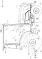
- Fig. 1 is a side view illustrating the whole tractor as an example of a work vehicle including a hydrostatic continuously variable transmission 12 according to the embodiment of the present invention.
- the tractor includes a vehicle body 1 including right and left front wheels 1F provided steerably and drivably and right and left rear wheels 1R provided drivably.
- the vehicle body 1 includes a motor section 2 in the front of the vehicle body 1 and a driving section 3 equipped with a drive cabin 30 in the rear of the vehicle body 1.
- the vehicle body 1 includes a vehicle body frame 10 via which the front wheels 1F and the rear wheels 1R support the motor section 2 and the driving section 3.
- the vehicle body frame 10 has a monocoque structure including an engine mount frame 10F supported by the front wheels 1F, an engine 20 included in the motor section 2, a power transmission case 11 having a front end portion connected to the rear of the engine 20, a hydrostatic continuously variable transmission 12 having a front end portion connected to a rear end portion of the power transmission case 11, and a transmission case 13 having a front end portion connected to a rear end portion of the hydrostatic continuously variable transmission 12.
- the transmission case 13 is supported by the rear wheels 1R.
- the rear of the transmission case 13 includes a link mechanism 15 including a pair of right and left lift arms 14 provided such that the lift arms 14 are swingable to lift and lower, and a power takeoff shaft 16 provided at the rear of the vehicle body frame 10.
- the tractor is configured such that a work device such as a rotary cultivating device (not illustrated) is connectable to the rear of the vehicle body via the link mechanism 15 in such a manner as to be liftable and lowerable, for example, and a driving force is transmittable to the connected rotary cultivating device from the power takeoff shaft 16.
- a work device such as a rotary cultivating device (not illustrated) is connectable to the rear of the vehicle body via the link mechanism 15 in such a manner as to be liftable and lowerable, for example, and a driving force is transmittable to the connected rotary cultivating device from the power takeoff shaft 16.
- the drive cabin 30 of the driving section 3 includes a driver seat 31, a steering wheel 32 as a steerage operation tool, and various operation tools such as a main select lever 33 as a gear shift tool and a shuttle lever 34 as a forward and rearward gear shift tool.
- the main select lever 33 is disposed on a front surface of a left rear-wheel fender 37 out of right and left rear-wheel fenders 37, so that the main select lever 33 is operable by a driver sitting in the driver seat 31.
- the shuttle lever 34 is provided on the left side of a steering column 38 to which the steering wheel 32 is attached, so that the shuttle lever 34 is operable by the left hand of the driver sitting in the driver seat 31.
- the hydrostatic continuously variable transmission 12 to which the power from the engine 20 is transmitted includes an axial-plunger hydraulic pump (not illustrated) and a hydraulic motor (not illustrated).
- a hydraulic motor not illustrated
- the swashplate angle (not illustrated) of the hydraulic pump is adjusted to change, the rotation speed of an output shaft (not illustrated), output from the hydraulic motor (not illustrated), is varied.
- the power from the output shaft is thus varied and transmitted to the transmission case 13.
- the swashplate angle of the hydraulic pump is changed by performing a rotation operation in forward and reverse directions on a trunnion shaft 12b projecting laterally outwardly from an external wall 12a of the hydrostatic continuously variable transmission 12.
- the rotation operation on the trunnion shaft 12b is performed by an electric motor 4 rotatable in forward and reverse directions and serving as an electric actuator provided outside the hydrostatic continuously variable transmission 12.
- respective operations of the main select lever 33 and the shuttle lever 34 are detected based on a detection signal from a volume (variable resistor) 33a provided at a swing fulcrum of the main select lever 33 and a detection signal from a volume (variable resistor) 34a provided at a swing fulcrum of the shuttle lever 34, and their detection results are input into an ECU (electronic control unit) 35.
- ECU electronic control unit
- the ECU 35 is connected to a power supply section 36, so that electric power for control is supplied from the power supply section 36.
- a control signal from the ECU 35 is transmitted to the electric motor 4 by CAN communication.
- Electric power for drive from the power supply section 36 is supplied to the electric motor 4, and the trunnion shaft 12b is rotated in the forward or reverse direction based on the control signal from the ECU 35, so that the swashplate angle of the hydrostatic continuously variable transmission 12 is changed.
- the main select lever 33 is variable continuously to a given shift position between a lowest speed position Ls as zero speed and a highest speed position Hs.
- the operation position of the main select lever 33 is detected by the volume 33a of the main select lever 33, and the detection signal is input into the ECU 35 as an instructed speed signal.
- the shuttle lever 34 is not variable continuously, but its operation position is switchable between three positions set in advance, i.e., a forward position FF, a neutral position NN, and a reverse position RR. Which one of the three positions the operation position of the shuttle lever 34 is varied to is detected by the volume 34a of the shuttle lever 34.
- the detection signal indicative of the operation position, detected by the volume 34a, is input into the ECU 35 as a signal indicative of an instructed advancing direction.
- the ECU 35 outputs a control signal to the electric motor 4 based on the detection signal from the volume 33a detecting the operation position of the main select lever 33 and the detection signal from the volume 34a detecting the operation position of the main shuttle lever 34, so that a traveling speed on an instructed forward or reverse side is achieved.
- the electric motor 4 rotates the trunnion shaft 12b in the forward or reverse direction based on the control signal from the ECU 35 to control the operation of the hydrostatic continuously variable transmission 12 such that driving to the instructed advancing direction is performed at an instructed driving speed.
- a relay operating device 5 is attached to the external wall 12a on the right side of the hydrostatic continuously variable transmission 12.
- the relay operating device 5 transmits a shifting operation by the electric motor 4 to the hydrostatic continuously variable transmission 12 and is configured as follows.
- the relay operating device 5 includes a linkage mechanism 5A configured to link a shifting shaft 41 of the electric motor 4 with the trunnion shaft 12b of the hydrostatic continuously variable transmission 12 to transmit the shifting operation of the electric motor 4 to the trunnion shaft 12b, and a biasing mechanism 5B configured to restrain the occurrence of backlash at a meshing portion between a drive gear 42 (corresponding to a first gear) and a driven gear 52 (corresponding to a second gear) provided in the linkage mechanism 5A.
- a linkage mechanism 5A configured to link a shifting shaft 41 of the electric motor 4 with the trunnion shaft 12b of the hydrostatic continuously variable transmission 12 to transmit the shifting operation of the electric motor 4 to the trunnion shaft 12b
- a biasing mechanism 5B configured to restrain the occurrence of backlash at a meshing portion between a drive gear 42 (corresponding to a first gear) and a driven gear 52 (corresponding to a second gear) provided in the linkage mechanism 5A.
- the linkage mechanism 5A and the biasing mechanism 5B are contained in a common casing 50.
- the casing 50 is removably fixed to the external wall 12a of the hydrostatic continuously variable transmission 12 by use of a fixing tool such as a check bolt 17.
- the linkage mechanism 5A includes the drive gear 42 as a first linkage section G1 linked with the shifting shaft 41 constituted by an output shaft of the electric motor 4, and the driven gear 52 as a second linkage section G2 linked with the trunnion shaft 12b.
- the electric motor 4 includes a motor case 40 containing a rotor or a stator, and the shifting shaft 41 projecting from the motor case 40.
- the motor case 40 is connected and fixed to the outside of a casing cover 50b (described later) of the casing 50.
- the shifting shaft 41 projecting from the motor case 40 is provided to penetrate through the casing cover 50b and enter a casing main body 50a of the casing 50.
- the drive gear 42 is provided to be outwardly engaged with the shifting shaft 41 to rotate together with an axial center P1 of the shifting shaft 41 in the forward or reverse direction.
- the driven gear 52 meshing with the drive gear 42 is formed in an end portion of a swing arm 51 configured to swing together with the trunnion shaft 12b. That is, the swing arm 51 is attached to swing together with the trunnion shaft 12b around an axial center P2 of the trunnion shaft 12b.
- the swing arm 51 has an edge portion at a position away from the axial center P2 of the trunnion shaft 12b which edge portion is provided with a gear having a pitch circle around the axial center P2 of the trunnion shaft 12b, and this gear constitutes the driven gear 52.
- the biasing mechanism 5B includes the swing arm 51 swinging together with the trunnion shaft 12b, and an operation body 55 configured to swing around an axial center P3 parallel to the axial center P2 of the trunnion shaft 12b.
- the swing arm 51 includes a cam 51a for guiding a cam follower 56 of the operation body 55.
- the cam 51a is formed in a portion closer to the axial center P2 of the trunnion shaft 12b than a portion where the driven gear 52 is formed in the swing arm 51.
- the cam 51a is linearly symmetrical across a virtual line segment a1 connecting the axial center P2 of the trunnion shaft 12b to the axial center P1 of the shifting shaft 41.
- the swing arm 51 is constituted by a single member and includes both the driven gear 52 and the cam 51a formed at different positions in the axial-center direction of the trunnion shaft 12b. That is, as illustrated in Figs. 3 and 4 , the swing arm 51 is constituted by a plate-shaped member attached to the trunnion shaft 12b and extending toward the shifting shaft 41, but the swing arm 51 is a stepped plate member in which the plate thickness on a side closer to the axial center P2 of the trunnion shaft 12b is thicker than the plate thickness on a side farther from the axial center P2.
- the cam 51a is formed in a stepped portion at a boundary between a thick portion having a large plate thickness on the side closer to the axial center P2 of the trunnion shaft 12b and a thin portion having a small plate thickness on the side farther from the axial center P2, and the driven gear 52 is formed in an edge portion of the swing arm 51 at a position farther from the axial center P2 of the trunnion shaft 12b than a portion where the cam 51a is present.
- the operation body 55 is supported on a shaft 53 having the axial center P3 parallel to the axial center P2 of the trunnion shaft 12b, and an eccentric portion 54 is formed integrally with the shaft 53.
- the operation body 55 includes a biasing spring 57 configured to bias the cam follower 56 toward the cam 51a.
- the biasing spring 57 is constituted by a torsion spring and is attached to the shaft 53 such that an intermediate portion of the biasing spring 57 is wound on the eccentric portion 54, with one end portion being wound on a shaft 56a of the cam follower 56 and the other end portion abutting with an inner surface of a surrounding wall of the casing 50.
- the inner surface of the surrounding wall of the casing 50 receives a reaction force to the other end portion of the biasing spring 57, so that the one end portion of the biasing spring 57 biases the cam follower 56 in a direction to always press the cam follower 56 against the cam 51a.
- the biasing force of the biasing spring 57 is not a biasing force that forcibly swings the swing arm 51 to return the trunnion shaft 12b to its neutral position but is a biasing force that can swing the swing arm 51 just by backlash between the drive gear 42 and the driven gear 52.
- the axial center P3 as a swing fulcrum for the operation body 55 is provided in an interval between a line segment b2 passing through the axial center P2 of the trunnion shaft 12b and a line segment b1 passing through the axial center P1 of the shifting shaft 41, in a direction perpendicular to the virtual line segment a1 connecting the axial center P2 of the trunnion shaft 12b and the axial center P1 of the shifting shaft 41.
- the casing 50 containing the linkage mechanism 5A and the biasing mechanism 5B includes the casing main body 50a having the surrounding wall, and the casing cover 50b in a cover shape covering the open side of the casing main body 50a.
- the casing 50 is fixed to the hydrostatic continuously variable transmission 12 with the bottom of the casing main body 50a facing the external wall 12a of the hydrostatic continuously variable transmission 12.
- the electric motor 4 is fixed to the casing cover 50b and can be attached to and detached from the hydrostatic continuously variable transmission 12 together with the casing 50.
- the casing cover 50b is provided with a volume (variable resistor) for feedback as a sensor 6 for detecting the rotated state of the trunnion shaft 12b.
- the sensor 6 detects the rotation angle of the trunnion shaft 12b rotated as the swinging angle of the swing arm 51 changes, so that the sensor 6 can detect the swashplate angle of the hydrostatic continuously variable transmission 12 in real time.
- a detection signal corresponding to the detected rotation angle of the trunnion shaft 12b is output to the ECU 35 as feedback information for detecting a change in the swashplate angle of the hydrostatic continuously variable transmission 12.
- the casing cover 50b partially includes an internal visual inspection section 58 as an opening or a transparent portion through which the inside of the casing 50 is visually observable.
- the internal visual inspection section 58 is formed at a position near the eccentric portion 54 and can be used usefully at the time when the adjustment state of the eccentric portion 54 is checked from outside.
- the electric motor 4 operates the trunnion shaft 12b to a neutral position as illustrated in Fig. 5 .
- the acting direction of a biasing force f1 of the biasing spring 57 biasing the cam follower 56 of the relay operating device 5 toward the cam 51a faces a side where the axial center P2 of the trunnion shaft 12b is present, at a position where the biasing force f1 coincides with the line segment a1 connecting the axial center P2 of the trunnion shaft 12b to the axial center P1 of the shifting shaft 41.
- the electric motor 4 rotates the drive gear 42 counterclockwise as illustrated in Fig. 6 , so that the swing arm 51 swings clockwise.
- the trunnion shaft 12b also rotates clockwise to change the swashplate angle of the hydrostatic continuously variable transmission 12 by a predetermined amount, so that forward traveling is performed.
- the acting direction of the reaction force f2 faces one side across the line segment a1, i.e., the left side in Fig. 6 .
- the biasing spring 57 acts to draw the swing arm 51 relatively to the right direction reverse to the direction (the left direction) of the reaction force f2 acting on the cam follower 56, so that the driven gear 52 on the swing arm 51 side approaches a direction fa where the driven gear 52 abuts with the tooth flank of the drive gear 42 as illustrated in an enlarged part in the figure, and hereby, the driven gear 52 is maintained at this position. That is, during forward traveling, the driven gear 52 on the swing arm 51 side is always driven with the driven gear 52 abutting the tooth flank of the drive gear 42 and is driven while backlash hardly occurs.
- the electric motor 4 rotates the drive gear 42 clockwise as illustrated in Fig. 7 , so that the swing arm 51 swings counterclockwise.
- the trunnion shaft 12b also rotates counterclockwise to change the swashplate angle of the hydrostatic continuously variable transmission 12 by a predetermined amount, so that reverse traveling is performed.
- the acting direction of the reaction force f2 faces one side across the line segment a1, i.e., the right side in Fig. 7 .
- the biasing spring 7 acts to press the swing arm 51 relatively to the left direction reverse to the direction (the right direction) of the reaction force f2 acting on the cam follower 56, so that the driven gear 52 on the swing arm 51 side approaches a direction fa where the driven gear 52 abuts with the tooth flank of the drive gear 42 as illustrated in an enlarged part in the figure, and hereby, the driven gear 52 is maintained at this position. That is, during reverse traveling, the driven gear 52 on the swing arm 51 side is always driven with the driven gear 52 abutting the tooth flank of the drive gear 42 and is driven while backlash hardly occurs.
- first linkage section G1 may include a plurality of gears
- second linkage section G2 may include a plurality of gears
- first linkage section G1 and the second linkage section G2 may both include a plurality of gears.
- the above embodiment describes, as an example, the configuration in which the swing arm 51 configured to swing together with the trunnion shaft 12b includes the cam 51a, and the operation body 55 includes the cam follower 56, but the present invention is not necessarily limited to this configuration.
- the swing arm 51 may include the cam follower 56
- the operation body 55 may include the cam 51a.
- the above embodiment describes, as an example, the configuration in which the swing arm 51 swinging together with the trunnion shaft 12b includes the driven gear 52 and the cam 51a, but the present invention is not necessarily limited to this configuration.
- an appropriate configuration such as a configuration in which the driven gear 52 and the swing arm 51 are attached to different members, or a configuration in which the driven gear 52 is directly attached to the trunnion shaft 12b, and the cam 51a is formed in the swing arm 51 provided separately from this can be employed.
- the above embodiment describes, as an example, the configuration in which the axial center P3 as the swing fulcrum for the operation body 55 is provided in the interval between the line segment b2 passing through the axial center P2 of the trunnion shaft 12b and the line segment b1 passing through the axial center P1 of the shifting shaft 41, in the direction perpendicular to the virtual line segment a1 connecting the trunnion shaft 12b and the shifting shaft 41, but the present invention is not necessarily limited to this configuration.
- the axial center P3 as the swing fulcrum for the operation body 55 may be provided at a position deviating from the interval between the line segment b2 and the line segment b 1.
- the above embodiment describes, as an example, the configuration in which the biasing mechanism 5B is contained in the casing 50, and the electric motor 4 is supported on the casing 50, but the present invention is not necessarily limited to this configuration.
- the casing 50 containing the biasing mechanism 5B may not be provided, and the biasing mechanism 5B and the electric motor 4 may be stored in an internal space of the vehicle body appropriately.
- the present invention is not necessarily limited to this configuration.
- the casing 50 of the relay operating device 5 may be attached to a portion other than the external wall 12a of the hydrostatic continuously variable transmission 12.
- the sensor 6 may detect the swashplate angle of the hydrostatic continuously variable transmission 12 by supporting the sensor 6 on the external wall 12a of the hydrostatic continuously variable transmission 12 such that the sensor 6 can detect the rotation angle of the trunnion shaft 12b at a position different from the casing 50.
- biasing spring 57 is a torsion spring contained in the casing 50, but the biasing spring 57 is not limited to a torsion spring, and an appropriate spring such as a coiled spring may be employed as the biasing spring 57.
- the above embodiment describes, as an example, the configuration in which the pump of the hydrostatic continuously variable transmission 12 is a main transmission mechanism for a tractor, but the present invention is not necessarily limited to this configuration.
- the pump of the hydrostatic continuously variable transmission 12 may be a transmission mechanism other than the main transmission mechanism for the tractor.
- the motor of the hydrostatic continuously variable transmission 12 may be used as a secondary transmission mechanism for the tractor.
- the present invention can be applied to various work vehicles such as a combine, a rice transplanter, and a haulage vehicle as well as the tractor as a work vehicle including a neutral operating device in an operation system from an electric motor to a hydrostatic continuously variable transmission.
Landscapes
- Engineering & Computer Science (AREA)
- General Engineering & Computer Science (AREA)
- Mechanical Engineering (AREA)
- Chemical & Material Sciences (AREA)
- Combustion & Propulsion (AREA)
- Transportation (AREA)
- Control Of Fluid Gearings (AREA)
- Gear-Shifting Mechanisms (AREA)
Abstract
Description
- The present invention relates to a work vehicle including a hydrostatic continuously variable transmission including a trunnion shaft controlled for shifting by an electric motor.
- This type of work vehicle may be configured such that a driven gear section provided in a relay crank lever is meshed with a drive gear provided in an output section of an electric motor so that a trunnion shaft of a hydrostatic continuously variable transmission is operated in forward and reverse directions in response to an output from the electric motor (see, for example, Patent Literature 1).
- Patent Literature 1:
Japanese Unexamined Patent Application Publication No. 2009-150414 - The configuration in which the trunnion shaft is operated in response to the output from the electric motor like the related art described in Patent Literature 1 is advantageous in that leakage of pressure oil or the like is less likely to cause instability in an operation position in comparison with a configuration in which the trunnion shaft is operated by use of a hydraulic actuator, for example.
- However, in a case where the electric motor is used, there is a problem such as instability in position due to backlash at a gear meshing portion used to decelerate an operational speed or the occurrence of chattering depending on the sensitivity of feedback, and there is room for improvement in such a point. In a case where a gear having a special structure such as a double-gear structure is used as means for avoiding the occurrence of backlash at such a gear meshing portion, for example, there is such a problem that adjustment is troublesome at the time of disassembling or the structure is complicated.
- The present invention is to provide a work vehicle that enables a stable shifting operation while the occurrence of backlash at a gear meshing portion provided in an operation system from an electric motor to a trunnion shaft of a hydrostatic continuously variable transmission is restrained with a simple structure.
- A work vehicle of the present invention includes: a hydrostatic continuously variable transmission for power output; an electric motor for shifting; a linkage mechanism configured to link a shifting shaft of the electric motor with a trunnion shaft of the hydrostatic continuously variable transmission, the linkage mechanism including a first linkage section including a first gear and linked with the shifting shaft, and a second linkage section which includes a second gear meshing with the first gear and which is linked with the trunnion shaft; and a biasing mechanism configured to press and bias the second gear against the first gear such that a tooth flank of the first gear abuts with a tooth flank of the second gear in a rotation direction reverse to a rotation direction of the first gear.
- In the present invention, the linkage mechanism configured to link the shifting shaft of the electric motor with the trunnion shaft of the hydrostatic continuously variable transmission includes the first gear and the second gear, and the biasing mechanism is provided between the first gear and the second gear such that the biasing mechanism biases the second gear against the first gear to bring their tooth flanks into contact with each other.
- Accordingly, the present invention has such an advantage that a shifting operation can be performed on the first gear and the second gear with their tooth flanks always abutting with each other, without a complicated structure such as a two-ply gear driving mechanism, and an operation from the shifting shaft of the electric motor to the trunnion shaft of the hydrostatic continuously variable transmission can be performed stably.
- In the present invention, it is preferable that: the biasing mechanism include a swing arm configured to swing together with the trunnion shaft, and an operation body configured to swing around an axial center parallel to an axial center of the trunnion shaft; the swing arm include a cam; the operation body include a cam follower; the biasing mechanism further include a biasing spring configured to bias the cam follower toward the cam; and the swing arm swing in a swinging direction causing the tooth flank of the second gear to approach the tooth flank of the first gear, in response to the biasing spring and the cam follower pressing the cam.
- With this configuration, the biasing mechanism can be configured with such a simple structure in which the biasing mechanism just includes the swing arm configured to swing together with the trunnion shaft, the operation body configured to swing around the axial center parallel to the axial center of the trunnion shaft, and the biasing spring configured to bias the cam follower of the operation body toward the cam of the swing arm.
- In the present invention, it is preferable that the second gear and the cam be provided in the swing arm, at different positions in an axial-center direction of the trunnion shaft.
- In this configuration, both the second gear and the cam are formed in the swing arm itself, so that the number of components can be made small and a planar area for disposition can be made small.
- In the present invention, it is preferable that the operation body have a swing fulcrum in an interval between a line segment passing through the axial center of the trunnion shaft and a line segment passing through an axial center of the shifting shaft in a direction perpendicular to a virtual line segment connecting the trunnion shaft to the shifting shaft.
- With this configuration, the cam follower of the operation arm and the cam of the swing arm can work effectively, and the biasing mechanism can be easily disposed collectively and compactly.
- In the present invention, it is preferable that the hydrostatic continuously variable transmission have an external wall to which a casing containing the linkage mechanism and the biasing mechanism is attached.
- With this configuration, the external wall of the hydrostatic continuously variable transmission can be used as attachment means for the casing containing the linkage mechanism and the biasing mechanism.
- In the present invention, it is preferable that the electric motor be supported on an outer portion of the casing.
- With this configuration, the casing containing the linkage mechanism and the biasing mechanism is used as support means for the electric motor so as to easily achieve simplification of the structure.
- In the present invention, it is preferable that the work vehicle further include a sensor supported on the casing and configured to detect a swashplate angle of the hydrostatic continuously variable transmission.
- With this configuration, the casing can be used as support means for the sensor.
- In the present invention, it is preferable that the biasing mechanism include an operation body configured to swing around an axial center parallel to an axial center of the trunnion shaft, and a biasing spring configured to bias a cam follower of the operation body toward a cam of a swing arm configured to swing together with the trunnion shaft; and the biasing spring be a torsion spring wound on a shaft supporting the operation body and contained in the casing.
- With this configuration, when a torsion spring wound on the shaft supporting the operation body and contained in the casing is used as the biasing spring, the structure of the biasing mechanism can be made relatively compact and easily simplified.
- In the present invention, it is preferable that the torsion spring have an end portion supported on the casing which end portion receives a reaction force acting on the cam follower.
- With this configuration, the casing can be used to receive the reaction force from the torsion spring, so that simplification of the structure can be achieved.
- In the present invention, it is preferable that the hydrostatic continuously variable transmission include a pump as a main transmission mechanism for a tractor, and the trunnion shaft be configured to change a swashplate angle of the pump.
- With this configuration, the pump of the hydrostatic continuously variable transmission can be used as the main transmission mechanism of the tractor.
- In the present invention, it is preferable that the hydrostatic continuously variable transmission include a motor as a secondary transmission mechanism for the tractor.
- With this configuration, the motor of the hydrostatic continuously variable transmission can be used as the secondary transmission mechanism of the tractor.
-
-
Fig. 1 is a side view illustrating the entire structure of a tractor; -
Fig. 2 is a block diagram illustrating a control circuit for a shifting operation system; -
Fig. 3 is a sectional view illustrating an electric motor for operating a trunnion shaft of a hydrostatic continuously variable transmission and a relay operating device; -
Fig. 4 is an explanatory view illustrating the electric motor for operating the trunnion shaft of the hydrostatic continuously variable transmission and the relay operating device; -
Fig. 5 is a side view illustrating a neutral biasing device with the trunnion shaft being operated to a neutral position; -
Fig. 6 is a side view illustrating the neutral biasing device with the trunnion shaft being operated to a highest speed position on a forward side; and -
Fig. 7 is a side view illustrating the neutral biasing device with the trunnion shaft being operated to a highest speed position on a reverse side. - An example of an embodiment of a work vehicle of the present invention will be hereinafter described with reference to the drawings.
- Note that a front-rear direction and a right-left direction in the description of the present embodiment are described as follows unless otherwise described. That is, at the time when a work vehicle to which the present invention is applied travels to work, an advancing direction to a forward side (see an arrow F in
Fig. 1 ) indicates "front," an advancing direction to a reverse side (see an arrow B inFig. 1 ) indicates "rear," a direction (see an arrow R inFig. 3 ) corresponding to the right side based on the work vehicle facing forward in the front-rear direction indicates "right," and a direction (see an arrow L inFig. 3 ) corresponding to the left side in the same state indicates "left." -
Fig. 1 is a side view illustrating the whole tractor as an example of a work vehicle including a hydrostatic continuouslyvariable transmission 12 according to the embodiment of the present invention. As illustrated in this figure, the tractor includes a vehicle body 1 including right and leftfront wheels 1F provided steerably and drivably and right and leftrear wheels 1R provided drivably. The vehicle body 1 includes a motor section 2 in the front of the vehicle body 1 and adriving section 3 equipped with adrive cabin 30 in the rear of the vehicle body 1. The vehicle body 1 includes avehicle body frame 10 via which thefront wheels 1F and therear wheels 1R support the motor section 2 and thedriving section 3. - The
vehicle body frame 10 has a monocoque structure including anengine mount frame 10F supported by thefront wheels 1F, anengine 20 included in the motor section 2, apower transmission case 11 having a front end portion connected to the rear of theengine 20, a hydrostatic continuouslyvariable transmission 12 having a front end portion connected to a rear end portion of thepower transmission case 11, and atransmission case 13 having a front end portion connected to a rear end portion of the hydrostatic continuouslyvariable transmission 12. - The
transmission case 13 is supported by therear wheels 1R. The rear of thetransmission case 13 includes alink mechanism 15 including a pair of right andleft lift arms 14 provided such that thelift arms 14 are swingable to lift and lower, and apower takeoff shaft 16 provided at the rear of thevehicle body frame 10. - The tractor is configured such that a work device such as a rotary cultivating device (not illustrated) is connectable to the rear of the vehicle body via the
link mechanism 15 in such a manner as to be liftable and lowerable, for example, and a driving force is transmittable to the connected rotary cultivating device from thepower takeoff shaft 16. - The
drive cabin 30 of thedriving section 3 includes adriver seat 31, asteering wheel 32 as a steerage operation tool, and various operation tools such as a mainselect lever 33 as a gear shift tool and ashuttle lever 34 as a forward and rearward gear shift tool. - The main
select lever 33 is disposed on a front surface of a left rear-wheel fender 37 out of right and left rear-wheel fenders 37, so that the mainselect lever 33 is operable by a driver sitting in thedriver seat 31. Theshuttle lever 34 is provided on the left side of asteering column 38 to which thesteering wheel 32 is attached, so that theshuttle lever 34 is operable by the left hand of the driver sitting in thedriver seat 31. - The hydrostatic continuously
variable transmission 12 to which the power from theengine 20 is transmitted includes an axial-plunger hydraulic pump (not illustrated) and a hydraulic motor (not illustrated). When the swashplate angle (not illustrated) of the hydraulic pump is adjusted to change, the rotation speed of an output shaft (not illustrated), output from the hydraulic motor (not illustrated), is varied. The power from the output shaft is thus varied and transmitted to thetransmission case 13. - The swashplate angle of the hydraulic pump is changed by performing a rotation operation in forward and reverse directions on a
trunnion shaft 12b projecting laterally outwardly from anexternal wall 12a of the hydrostatic continuouslyvariable transmission 12. The rotation operation on thetrunnion shaft 12b is performed by anelectric motor 4 rotatable in forward and reverse directions and serving as an electric actuator provided outside the hydrostatic continuouslyvariable transmission 12. - As illustrated in
Fig. 2 , respective operations of the mainselect lever 33 and theshuttle lever 34 are detected based on a detection signal from a volume (variable resistor) 33a provided at a swing fulcrum of the mainselect lever 33 and a detection signal from a volume (variable resistor) 34a provided at a swing fulcrum of theshuttle lever 34, and their detection results are input into an ECU (electronic control unit) 35. - The
ECU 35 is connected to apower supply section 36, so that electric power for control is supplied from thepower supply section 36. A control signal from theECU 35 is transmitted to theelectric motor 4 by CAN communication. Electric power for drive from thepower supply section 36 is supplied to theelectric motor 4, and thetrunnion shaft 12b is rotated in the forward or reverse direction based on the control signal from theECU 35, so that the swashplate angle of the hydrostatic continuouslyvariable transmission 12 is changed. - The main
select lever 33 is variable continuously to a given shift position between a lowest speed position Ls as zero speed and a highest speed position Hs. The operation position of the mainselect lever 33 is detected by thevolume 33a of the mainselect lever 33, and the detection signal is input into theECU 35 as an instructed speed signal. - The
shuttle lever 34 is not variable continuously, but its operation position is switchable between three positions set in advance, i.e., a forward position FF, a neutral position NN, and a reverse position RR. Which one of the three positions the operation position of theshuttle lever 34 is varied to is detected by thevolume 34a of theshuttle lever 34. The detection signal indicative of the operation position, detected by thevolume 34a, is input into theECU 35 as a signal indicative of an instructed advancing direction. - The
ECU 35 outputs a control signal to theelectric motor 4 based on the detection signal from thevolume 33a detecting the operation position of the mainselect lever 33 and the detection signal from thevolume 34a detecting the operation position of themain shuttle lever 34, so that a traveling speed on an instructed forward or reverse side is achieved. - The
electric motor 4 rotates thetrunnion shaft 12b in the forward or reverse direction based on the control signal from theECU 35 to control the operation of the hydrostatic continuouslyvariable transmission 12 such that driving to the instructed advancing direction is performed at an instructed driving speed. - As illustrated in
Figs. 1 ,3 ,4 , arelay operating device 5 is attached to theexternal wall 12a on the right side of the hydrostatic continuouslyvariable transmission 12. - The
relay operating device 5 transmits a shifting operation by theelectric motor 4 to the hydrostatic continuouslyvariable transmission 12 and is configured as follows. - As illustrated in
Figs. 3 ,4 , therelay operating device 5 includes alinkage mechanism 5A configured to link a shiftingshaft 41 of theelectric motor 4 with thetrunnion shaft 12b of the hydrostatic continuouslyvariable transmission 12 to transmit the shifting operation of theelectric motor 4 to thetrunnion shaft 12b, and abiasing mechanism 5B configured to restrain the occurrence of backlash at a meshing portion between a drive gear 42 (corresponding to a first gear) and a driven gear 52 (corresponding to a second gear) provided in thelinkage mechanism 5A. - The
linkage mechanism 5A and thebiasing mechanism 5B are contained in acommon casing 50. Thecasing 50 is removably fixed to theexternal wall 12a of the hydrostatic continuouslyvariable transmission 12 by use of a fixing tool such as acheck bolt 17. - The
linkage mechanism 5A includes thedrive gear 42 as a first linkage section G1 linked with the shiftingshaft 41 constituted by an output shaft of theelectric motor 4, and the drivengear 52 as a second linkage section G2 linked with thetrunnion shaft 12b. - The
electric motor 4 includes amotor case 40 containing a rotor or a stator, and the shiftingshaft 41 projecting from themotor case 40. Themotor case 40 is connected and fixed to the outside of acasing cover 50b (described later) of thecasing 50. The shiftingshaft 41 projecting from themotor case 40 is provided to penetrate through thecasing cover 50b and enter a casingmain body 50a of thecasing 50. - The
drive gear 42 is provided to be outwardly engaged with the shiftingshaft 41 to rotate together with an axial center P1 of the shiftingshaft 41 in the forward or reverse direction. The drivengear 52 meshing with thedrive gear 42 is formed in an end portion of aswing arm 51 configured to swing together with thetrunnion shaft 12b. That is, theswing arm 51 is attached to swing together with thetrunnion shaft 12b around an axial center P2 of thetrunnion shaft 12b. Theswing arm 51 has an edge portion at a position away from the axial center P2 of thetrunnion shaft 12b which edge portion is provided with a gear having a pitch circle around the axial center P2 of thetrunnion shaft 12b, and this gear constitutes the drivengear 52. - The
biasing mechanism 5B includes theswing arm 51 swinging together with thetrunnion shaft 12b, and anoperation body 55 configured to swing around an axial center P3 parallel to the axial center P2 of thetrunnion shaft 12b. Theswing arm 51 includes acam 51a for guiding acam follower 56 of theoperation body 55. Thecam 51a is formed in a portion closer to the axial center P2 of thetrunnion shaft 12b than a portion where the drivengear 52 is formed in theswing arm 51. - As illustrated in
Figs. 4 and5 , when thetrunnion shaft 12b of the hydrostatic continuouslyvariable transmission 12 is placed at a neutral position, thecam 51a is linearly symmetrical across a virtual line segment a1 connecting the axial center P2 of thetrunnion shaft 12b to the axial center P1 of the shiftingshaft 41. - The
swing arm 51 is constituted by a single member and includes both the drivengear 52 and thecam 51a formed at different positions in the axial-center direction of thetrunnion shaft 12b. That is, as illustrated inFigs. 3 and4 , theswing arm 51 is constituted by a plate-shaped member attached to thetrunnion shaft 12b and extending toward the shiftingshaft 41, but theswing arm 51 is a stepped plate member in which the plate thickness on a side closer to the axial center P2 of thetrunnion shaft 12b is thicker than the plate thickness on a side farther from the axial center P2. - The
cam 51a is formed in a stepped portion at a boundary between a thick portion having a large plate thickness on the side closer to the axial center P2 of thetrunnion shaft 12b and a thin portion having a small plate thickness on the side farther from the axial center P2, and the drivengear 52 is formed in an edge portion of theswing arm 51 at a position farther from the axial center P2 of thetrunnion shaft 12b than a portion where thecam 51a is present. - The
operation body 55 is supported on ashaft 53 having the axial center P3 parallel to the axial center P2 of thetrunnion shaft 12b, and aneccentric portion 54 is formed integrally with theshaft 53. - The
operation body 55 includes a biasingspring 57 configured to bias thecam follower 56 toward thecam 51a. The biasingspring 57 is constituted by a torsion spring and is attached to theshaft 53 such that an intermediate portion of the biasingspring 57 is wound on theeccentric portion 54, with one end portion being wound on ashaft 56a of thecam follower 56 and the other end portion abutting with an inner surface of a surrounding wall of thecasing 50. - With this configuration, the inner surface of the surrounding wall of the
casing 50 receives a reaction force to the other end portion of the biasingspring 57, so that the one end portion of the biasingspring 57 biases thecam follower 56 in a direction to always press thecam follower 56 against thecam 51a. - The biasing force of the biasing
spring 57 is not a biasing force that forcibly swings theswing arm 51 to return thetrunnion shaft 12b to its neutral position but is a biasing force that can swing theswing arm 51 just by backlash between thedrive gear 42 and the drivengear 52. - As illustrated in
Fig. 4 , the axial center P3 as a swing fulcrum for theoperation body 55 is provided in an interval between a line segment b2 passing through the axial center P2 of thetrunnion shaft 12b and a line segment b1 passing through the axial center P1 of the shiftingshaft 41, in a direction perpendicular to the virtual line segment a1 connecting the axial center P2 of thetrunnion shaft 12b and the axial center P1 of the shiftingshaft 41. - When the
eccentric portion 54 formed integrally in theshaft 53 is rotated around the axial center P3, the biasing direction of the biasingspring 57 attached to be wound on theeccentric portion 54 is finely adjusted, so that a corresponding position of thecam follower 56 to thecam 51a can be finely adjusted. - As illustrated in
Figs. 3 and4 , thecasing 50 containing thelinkage mechanism 5A and thebiasing mechanism 5B includes the casingmain body 50a having the surrounding wall, and thecasing cover 50b in a cover shape covering the open side of the casingmain body 50a. - As illustrated in
Fig. 3 , thecasing 50 is fixed to the hydrostatic continuouslyvariable transmission 12 with the bottom of the casingmain body 50a facing theexternal wall 12a of the hydrostatic continuouslyvariable transmission 12. Theelectric motor 4 is fixed to thecasing cover 50b and can be attached to and detached from the hydrostatic continuouslyvariable transmission 12 together with thecasing 50. - As illustrated in
Figs. 3 ,4 , thecasing cover 50b is provided with a volume (variable resistor) for feedback as asensor 6 for detecting the rotated state of thetrunnion shaft 12b. Thesensor 6 detects the rotation angle of thetrunnion shaft 12b rotated as the swinging angle of theswing arm 51 changes, so that thesensor 6 can detect the swashplate angle of the hydrostatic continuouslyvariable transmission 12 in real time. A detection signal corresponding to the detected rotation angle of thetrunnion shaft 12b is output to theECU 35 as feedback information for detecting a change in the swashplate angle of the hydrostatic continuouslyvariable transmission 12. - Further, as illustrated in
Fig. 4 , thecasing cover 50b partially includes an internalvisual inspection section 58 as an opening or a transparent portion through which the inside of thecasing 50 is visually observable. The internalvisual inspection section 58 is formed at a position near theeccentric portion 54 and can be used usefully at the time when the adjustment state of theeccentric portion 54 is checked from outside. - An operation form of the
relay operating device 5 at the time when the shifting operation of theelectric motor 4 is transmitted to thetrunnion shaft 12b will be described based onFigs. 2 ,5 to 7 . - In a case where the main
select lever 33 is operated to the lowest speed position Ls, or in a case where theshuttle lever 34 is operated to the neutral position NN, theelectric motor 4 operates thetrunnion shaft 12b to a neutral position as illustrated inFig. 5 . - In this state, the acting direction of a biasing force f1 of the biasing
spring 57 biasing thecam follower 56 of therelay operating device 5 toward thecam 51a faces a side where the axial center P2 of thetrunnion shaft 12b is present, at a position where the biasing force f1 coincides with the line segment a1 connecting the axial center P2 of thetrunnion shaft 12b to the axial center P1 of the shiftingshaft 41. - At this time, the direction of a reaction force of the
cam 51a at a position where thecam 51a abuts with thecam follower 56 corresponds to directions of reaction forces f2, f2 illustrated inFig. 5 . Respective acting directions of the reaction forces f2, f2 are directed in reverse directions across the line segment a1 and intersect with each other at generally equal angles, so that theswing arm 51 is maintained at the neutral position without swinging clockwise or counterclockwise direction around the axial center P2 of thetrunnion shaft 12b. - In a case where the
shuttle lever 34 is operated to the forward position FF, and the mainselect lever 33 is operated to approach the highest speed position Hs from the lowest speed position Ls, theelectric motor 4 rotates thedrive gear 42 counterclockwise as illustrated inFig. 6 , so that theswing arm 51 swings clockwise. As a result, thetrunnion shaft 12b also rotates clockwise to change the swashplate angle of the hydrostatic continuouslyvariable transmission 12 by a predetermined amount, so that forward traveling is performed. - At this time, the direction of the reaction force of the
cam 51a at the position where thecam 51a abuts with thecam follower 56 corresponds to a direction of the reaction force f2 illustrated inFig. 6 . - The acting direction of the reaction force f2 faces one side across the line segment a1, i.e., the left side in
Fig. 6 . At this time, since the distance from the axial center P3 of theoperation body 55 to thecam follower 56 is constant, the biasingspring 57 acts to draw theswing arm 51 relatively to the right direction reverse to the direction (the left direction) of the reaction force f2 acting on thecam follower 56, so that the drivengear 52 on theswing arm 51 side approaches a direction fa where the drivengear 52 abuts with the tooth flank of thedrive gear 42 as illustrated in an enlarged part in the figure, and hereby, the drivengear 52 is maintained at this position. That is, during forward traveling, the drivengear 52 on theswing arm 51 side is always driven with the drivengear 52 abutting the tooth flank of thedrive gear 42 and is driven while backlash hardly occurs. - In a case where the
shuttle lever 34 is operated to the reverse position RR, and the mainselect lever 33 is operated to approach the highest speed position Hs from the lowest speed position Ls, theelectric motor 4 rotates thedrive gear 42 clockwise as illustrated inFig. 7 , so that theswing arm 51 swings counterclockwise. As a result, thetrunnion shaft 12b also rotates counterclockwise to change the swashplate angle of the hydrostatic continuouslyvariable transmission 12 by a predetermined amount, so that reverse traveling is performed. - At this time, the direction of the reaction force of the
cam 51a at the position where thecam 51a abuts with thecam follower 56 corresponds to a direction of the reaction force f2 illustrated inFig. 7 . - The acting direction of the reaction force f2 faces one side across the line segment a1, i.e., the right side in
Fig. 7 . At this time, since the distance from the axial center P3 of theoperation body 55 to thecam follower 56 is constant, the biasing spring 7 acts to press theswing arm 51 relatively to the left direction reverse to the direction (the right direction) of the reaction force f2 acting on thecam follower 56, so that the drivengear 52 on theswing arm 51 side approaches a direction fa where the drivengear 52 abuts with the tooth flank of thedrive gear 42 as illustrated in an enlarged part in the figure, and hereby, the drivengear 52 is maintained at this position. That is, during reverse traveling, the drivengear 52 on theswing arm 51 side is always driven with the drivengear 52 abutting the tooth flank of thedrive gear 42 and is driven while backlash hardly occurs. - Alternative embodiments will be described below. Some of the following alternative embodiments may be used in combination as long as no inconsistency occurs. Note that the scope of the present invention is not limited to those embodiments.
- (1) The above embodiment describes, as an example, the configuration in which the first linkage section G1 linked with the shifting
shaft 41 includes asingle drive gear 42, and the second linkage section G2 linked with thetrunnion shaft 12b includes a single drivengear 52, but the present invention is not necessarily limited to this configuration. - For example, the first linkage section G1 may include a plurality of gears, the second linkage section G2 may include a plurality of gears, or the first linkage section G1 and the second linkage section G2 may both include a plurality of gears.
- As the other configuration, a configuration similar to that in the above embodiment should be employed.
- (2) The above embodiment describes, as an example, the configuration in which the
swing arm 51 configured to swing together with thetrunnion shaft 12b includes thecam 51a, and theoperation body 55 includes thecam follower 56, but the present invention is not necessarily limited to this configuration. For example, theswing arm 51 may include thecam follower 56, and theoperation body 55 may include thecam 51a. - As the other configuration, a configuration similar to that in the above embodiment should be employed.
- (3) The above embodiment describes, as an example, the configuration in which the
swing arm 51 swinging together with thetrunnion shaft 12b includes the drivengear 52 and thecam 51a, but the present invention is not necessarily limited to this configuration. For example, an appropriate configuration such as a configuration in which the drivengear 52 and theswing arm 51 are attached to different members, or a configuration in which the drivengear 52 is directly attached to thetrunnion shaft 12b, and thecam 51a is formed in theswing arm 51 provided separately from this can be employed. - As the other configuration, a configuration similar to that in the above embodiment should be employed.
- (4) The above embodiment describes, as an example, the configuration in which the axial center P3 as the swing fulcrum for the
operation body 55 is provided in the interval between the line segment b2 passing through the axial center P2 of thetrunnion shaft 12b and the line segment b1 passing through the axial center P1 of the shiftingshaft 41, in the direction perpendicular to the virtual line segment a1 connecting thetrunnion shaft 12b and the shiftingshaft 41, but the present invention is not necessarily limited to this configuration. For example, the axial center P3 as the swing fulcrum for theoperation body 55 may be provided at a position deviating from the interval between the line segment b2 and the line segment b 1. - As the other configuration, a configuration similar to that in the above embodiment should be employed.
- (5) The above embodiment describes, as an example, the configuration in which the
biasing mechanism 5B is contained in thecasing 50, and theelectric motor 4 is supported on thecasing 50, but the present invention is not necessarily limited to this configuration. For example, thecasing 50 containing thebiasing mechanism 5B may not be provided, and thebiasing mechanism 5B and theelectric motor 4 may be stored in an internal space of the vehicle body appropriately. - As the other configuration, a configuration similar to that in the above embodiment should be employed.
- (6) The above embodiment describes, as an example, the configuration in which the
casing 50 of therelay operating device 5 is attached to theexternal wall 12a of the hydrostatic continuouslyvariable transmission 12 and thesensor 6 for detecting the swashplate angle of the hydrostatic continuouslyvariable transmission 12 is supported by thecasing 50, but the present invention is not necessarily limited to this configuration. For example, thecasing 50 of therelay operating device 5 may be attached to a portion other than theexternal wall 12a of the hydrostatic continuouslyvariable transmission 12. In this case, thesensor 6 may detect the swashplate angle of the hydrostatic continuouslyvariable transmission 12 by supporting thesensor 6 on theexternal wall 12a of the hydrostatic continuouslyvariable transmission 12 such that thesensor 6 can detect the rotation angle of thetrunnion shaft 12b at a position different from thecasing 50. - As the other configuration, a configuration similar to that in the above embodiment should be employed.
- (7) The above embodiment describes, as an example, the configuration in which the biasing
spring 57 is a torsion spring contained in thecasing 50, but the biasingspring 57 is not limited to a torsion spring, and an appropriate spring such as a coiled spring may be employed as the biasingspring 57. - As the other configuration, a configuration similar to that in the above embodiment should be employed.
- (8) The above embodiment describes, as an example, the configuration in which the pump of the hydrostatic continuously
variable transmission 12 is a main transmission mechanism for a tractor, but the present invention is not necessarily limited to this configuration. For example, the pump of the hydrostatic continuouslyvariable transmission 12 may be a transmission mechanism other than the main transmission mechanism for the tractor. - Further, the motor of the hydrostatic continuously
variable transmission 12 may be used as a secondary transmission mechanism for the tractor. - As the other configuration, a configuration similar to that in the above embodiment should be employed.
- The present invention can be applied to various work vehicles such as a combine, a rice transplanter, and a haulage vehicle as well as the tractor as a work vehicle including a neutral operating device in an operation system from an electric motor to a hydrostatic continuously variable transmission.
-
- 4
- electric motor
- 5A
- linkage mechanism
- 5B
- biasing mechanism
- 6
- sensor
- 12
- hydrostatic continuously variable transmission
- 12b
- trunnion shaft
- 41
- shifting shaft
- 42
- first gear (drive gear)
- 50
- casing
- 51
- swing arm
- 51a
- cam
- 52
- second gear (driven gear)
- 55
- operation body
- 56
- cam follower
- 57
- biasing spring
- G1
- first linkage section
- G2
- second linkage section
- P1
- axial center
- P2
- axial center
- P3
- axial center (swing fulcrum)
- a1
- virtual line segment
- b1
- line segment
- b2
- line segment
Claims (11)
- A work vehicle, comprising:a hydrostatic continuously variable transmission for power output;an electric motor for shifting;a linkage mechanism configured to link a shifting shaft of the electric motor with a trunnion shaft of the hydrostatic continuously variable transmission, the linkage mechanism including a first linkage section linked with the shifting shaft, and a second linkage section linked with the trunnion shaft; anda biasing mechanism configured to press and bias a second gear of the second linkage section which second gear meshes with a first gear of the first linkage section against the first gear such that a tooth flank of the second gear abuts with a tooth flank of the first gear in a rotation direction reverse to a rotation direction of the first gear.
- The work vehicle according to claim 1, whereinthe biasing mechanism includes:a swing arm configured to swing together with the trunnion shaft; andan operation body configured to swing around an axial center parallel to an axial center of the trunnion shaft,the swing arm includes a cam,the operation body includes a cam follower,the biasing mechanism further includes a biasing spring configured to bias the cam follower toward the cam, andthe swing arm swings in a swinging direction causing the tooth flank of the second gear to approach the tooth flank of the first gear, in response to the biasing spring and the cam follower pressing the cam.
- The work vehicle according to claim 2, wherein
the second gear and the cam are provided in the swing arm, at different positions in an axial-center direction of the trunnion shaft. - The work vehicle according to claim 2 or 3, wherein
the operation body has a swing fulcrum in an interval between a line segment passing through the axial center of the trunnion shaft and a line segment passing through an axial center of the shifting shaft in a direction perpendicular to a virtual line segment connecting the trunnion shaft to the shifting shaft. - The work vehicle according to any one of claims 1 to 4, wherein
the hydrostatic continuously variable transmission has an external wall to which a casing containing the linkage mechanism and the biasing mechanism is attached. - The work vehicle according to claim 5, wherein
the electric motor is supported on an outer portion of the casing. - The work vehicle according to claim 5 or 6, further comprising
a sensor supported on the casing and configured to detect a swashplate angle of the hydrostatic continuously variable transmission. - The work vehicle according to any one of claims 5 to 7, whereinthe biasing mechanism includes:an operation body configured to swing around an axial center parallel to an axial center of the trunnion shaft; anda biasing spring configured to bias a cam follower of the operation body toward a cam of a swing arm configured to swing together with the trunnion shaft, andthe biasing spring is a torsion spring wound on a shaft supporting the operation body and contained in the casing.
- The work vehicle according to claim 8, wherein
the torsion spring has an end portion supported on the casing which end portion receives a reaction force acting on the cam follower. - The work vehicle according to any one of claims 1 to 9, whereinthe hydrostatic continuously variable transmission includes a pump as a main transmission mechanism for a tractor, andthe trunnion shaft is configured to change a swashplate angle of the pump.
- The work vehicle according to claim 10, wherein
the hydrostatic continuously variable transmission includes a motor as a secondary transmission mechanism for the tractor.
Applications Claiming Priority (2)
| Application Number | Priority Date | Filing Date | Title |
|---|---|---|---|
| JP2021211674A JP7542517B2 (en) | 2021-12-24 | 2021-12-24 | Work vehicle |
| PCT/JP2022/046884 WO2023120523A1 (en) | 2021-12-24 | 2022-12-20 | Work vehicle |
Publications (2)
| Publication Number | Publication Date |
|---|---|
| EP4455516A1 true EP4455516A1 (en) | 2024-10-30 |
| EP4455516A4 EP4455516A4 (en) | 2025-12-24 |
Family
ID=86902519
Family Applications (1)
| Application Number | Title | Priority Date | Filing Date |
|---|---|---|---|
| EP22911225.5A Pending EP4455516A4 (en) | 2021-12-24 | 2022-12-20 | WORK VEHICLE |
Country Status (4)
| Country | Link |
|---|---|
| US (1) | US20240295265A1 (en) |
| EP (1) | EP4455516A4 (en) |
| JP (1) | JP7542517B2 (en) |
| WO (1) | WO2023120523A1 (en) |
Families Citing this family (1)
| Publication number | Priority date | Publication date | Assignee | Title |
|---|---|---|---|---|
| WO2026089426A1 (en) * | 2024-10-21 | 2026-04-30 | 엘에스엠트론 주식회사 | Motor-driven hydrostatic transmission for agricultural work vehicle |
Family Cites Families (10)
| Publication number | Priority date | Publication date | Assignee | Title |
|---|---|---|---|---|
| FR1431758A (en) * | 1965-01-28 | 1966-03-18 | Richier Sa | Remote control device, particularly applicable to hydraulic transmissions |
| JPH1054461A (en) * | 1996-08-09 | 1998-02-24 | Kubota Corp | Continuously variable transmission for work equipment |
| FR2777335A1 (en) * | 1998-04-14 | 1999-10-15 | Mannesmann Sachs Ag | ACTUATION SYSTEM FOR AUTOMATICALLY MANEUVERING A GEARBOX |
| US6470764B1 (en) * | 1999-10-27 | 2002-10-29 | Nsk Ltd. | Electric drive device for transmission |
| US7165398B1 (en) * | 2002-11-07 | 2007-01-23 | Hydro-Gear Limited Partnership | System and method for electronic actuation of axle driving apparatus |
| JP4626740B2 (en) | 2003-11-27 | 2011-02-09 | 井関農機株式会社 | Working machine |
| JP2009150414A (en) | 2007-12-18 | 2009-07-09 | Iseki & Co Ltd | Continuously variable work vehicle |
| JP5261446B2 (en) | 2010-07-28 | 2013-08-14 | 株式会社クボタ | Neutral biasing device for hydrostatic continuously variable transmission |
| JP5577182B2 (en) | 2010-08-04 | 2014-08-20 | 株式会社 神崎高級工機製作所 | Electric operation type hydraulic actuator unit and hydraulic four-wheel drive working vehicle |
| US9114798B1 (en) * | 2012-12-12 | 2015-08-25 | Hydro-Gear Limited Partnership | Electric actuator for drive apparatus |
-
2021
- 2021-12-24 JP JP2021211674A patent/JP7542517B2/en active Active
-
2022
- 2022-12-20 WO PCT/JP2022/046884 patent/WO2023120523A1/en not_active Ceased
- 2022-12-20 EP EP22911225.5A patent/EP4455516A4/en active Pending
-
2024
- 2024-05-15 US US18/664,345 patent/US20240295265A1/en active Pending
Also Published As
| Publication number | Publication date |
|---|---|
| JP2023095653A (en) | 2023-07-06 |
| US20240295265A1 (en) | 2024-09-05 |
| JP7542517B2 (en) | 2024-08-30 |
| WO2023120523A1 (en) | 2023-06-29 |
| EP4455516A4 (en) | 2025-12-24 |
Similar Documents
| Publication | Publication Date | Title |
|---|---|---|
| US7520833B2 (en) | Vehicular driving force distribution system | |
| US20060042858A1 (en) | Steer-by-wire steering apparatus with redundant electric motor drive systems | |
| JP2010143240A (en) | Steering control device | |
| US6564891B2 (en) | Power take-off assembly for working vehicles | |
| JP4327362B2 (en) | Transmission and steering gear transmission for vehicles | |
| US20240295265A1 (en) | Work vehicle | |
| US20060052201A1 (en) | Active front steering actuator | |
| JP5101388B2 (en) | Shift operating device for work vehicle | |
| CN114585551B (en) | Steering gear of electromechanical steering system of vehicle and electromechanical steering system of vehicle | |
| JP2003291673A (en) | Traveling vehicle | |
| KR101031057B1 (en) | Active Front Wheel Steering System for Vehicles | |
| US5244052A (en) | Steering control unit for multiple steerable axles | |
| JP4898256B2 (en) | Transmission for automobile | |
| WO2003082620A1 (en) | Traveling vehicle | |
| JP2025093793A (en) | Work vehicle | |
| JP4599682B2 (en) | Tractor | |
| JP5242534B2 (en) | Shifting operation mechanism | |
| JP2025093792A (en) | Work vehicle | |
| JP4257100B2 (en) | PTO drive device for tractor | |
| JP4519503B2 (en) | Four-wheel drive / front-wheel acceleration drive switching mechanism | |
| JPH0734778Y2 (en) | 4-wheel steering mode switching device | |
| JP5245427B2 (en) | Work vehicle | |
| JP2012136068A (en) | Working vehicle | |
| CN117249206A (en) | Steering system and agricultural operation machine with same | |
| JP2013032809A (en) | Transmission of working vehicle |
Legal Events
| Date | Code | Title | Description |
|---|---|---|---|
| STAA | Information on the status of an ep patent application or granted ep patent |
Free format text: STATUS: THE INTERNATIONAL PUBLICATION HAS BEEN MADE |
|
| PUAI | Public reference made under article 153(3) epc to a published international application that has entered the european phase |
Free format text: ORIGINAL CODE: 0009012 |
|
| STAA | Information on the status of an ep patent application or granted ep patent |
Free format text: STATUS: REQUEST FOR EXAMINATION WAS MADE |
|
| 17P | Request for examination filed |
Effective date: 20240523 |
|
| AK | Designated contracting states |
Kind code of ref document: A1 Designated state(s): AL AT BE BG CH CY CZ DE DK EE ES FI FR GB GR HR HU IE IS IT LI LT LU LV MC ME MK MT NL NO PL PT RO RS SE SI SK SM TR |
|
| DAV | Request for validation of the european patent (deleted) | ||
| DAX | Request for extension of the european patent (deleted) | ||
| REG | Reference to a national code |
Ref country code: DE Ref legal event code: R079 Free format text: PREVIOUS MAIN CLASS: F16H0061320000 Ipc: F16H0061435000 |
|
| A4 | Supplementary search report drawn up and despatched |
Effective date: 20251124 |
|
| RIC1 | Information provided on ipc code assigned before grant |
Ipc: F16H 61/435 20100101AFI20251118BHEP Ipc: F16H 61/32 20060101ALI20251118BHEP |