EP4455501A1 - Retainer, bearing, transmission and method of manufacturing retainer - Google Patents
Retainer, bearing, transmission and method of manufacturing retainer Download PDFInfo
- Publication number
- EP4455501A1 EP4455501A1 EP24164154.7A EP24164154A EP4455501A1 EP 4455501 A1 EP4455501 A1 EP 4455501A1 EP 24164154 A EP24164154 A EP 24164154A EP 4455501 A1 EP4455501 A1 EP 4455501A1
- Authority
- EP
- European Patent Office
- Prior art keywords
- fall
- diameter ring
- diameter
- small
- retainer
- Prior art date
- Legal status (The legal status is an assumption and is not a legal conclusion. Google has not performed a legal analysis and makes no representation as to the accuracy of the status listed.)
- Pending
Links
Images



Classifications
-
- B—PERFORMING OPERATIONS; TRANSPORTING
- B29—WORKING OF PLASTICS; WORKING OF SUBSTANCES IN A PLASTIC STATE IN GENERAL
- B29C—SHAPING OR JOINING OF PLASTICS; SHAPING OF MATERIAL IN A PLASTIC STATE, NOT OTHERWISE PROVIDED FOR; AFTER-TREATMENT OF THE SHAPED PRODUCTS, e.g. REPAIRING
- B29C45/00—Injection moulding, i.e. forcing the required volume of moulding material through a nozzle into a closed mould; Apparatus therefor
- B29C45/14—Injection moulding, i.e. forcing the required volume of moulding material through a nozzle into a closed mould; Apparatus therefor incorporating preformed parts or layers, e.g. injection moulding around inserts or for coating articles
- B29C45/14008—Inserting articles into the mould
-
- F—MECHANICAL ENGINEERING; LIGHTING; HEATING; WEAPONS; BLASTING
- F16—ENGINEERING ELEMENTS AND UNITS; GENERAL MEASURES FOR PRODUCING AND MAINTAINING EFFECTIVE FUNCTIONING OF MACHINES OR INSTALLATIONS; THERMAL INSULATION IN GENERAL
- F16C—SHAFTS; FLEXIBLE SHAFTS; ELEMENTS OR CRANKSHAFT MECHANISMS; ROTARY BODIES OTHER THAN GEARING ELEMENTS; BEARINGS
- F16C33/00—Parts of bearings; Special methods for making bearings or parts thereof
- F16C33/30—Parts of ball or roller bearings
- F16C33/46—Cages for rollers or needles
- F16C33/4617—Massive or moulded cages having cage pockets surrounding the rollers, e.g. machined window cages
- F16C33/4623—Massive or moulded cages having cage pockets surrounding the rollers, e.g. machined window cages formed as one-piece cages, i.e. monoblock cages
-
- B—PERFORMING OPERATIONS; TRANSPORTING
- B29—WORKING OF PLASTICS; WORKING OF SUBSTANCES IN A PLASTIC STATE IN GENERAL
- B29C—SHAPING OR JOINING OF PLASTICS; SHAPING OF MATERIAL IN A PLASTIC STATE, NOT OTHERWISE PROVIDED FOR; AFTER-TREATMENT OF THE SHAPED PRODUCTS, e.g. REPAIRING
- B29C45/00—Injection moulding, i.e. forcing the required volume of moulding material through a nozzle into a closed mould; Apparatus therefor
- B29C45/17—Component parts, details or accessories; Auxiliary operations
- B29C45/40—Removing or ejecting moulded articles
- B29C45/4005—Ejector constructions; Ejector operating mechanisms
-
- F—MECHANICAL ENGINEERING; LIGHTING; HEATING; WEAPONS; BLASTING
- F16—ENGINEERING ELEMENTS AND UNITS; GENERAL MEASURES FOR PRODUCING AND MAINTAINING EFFECTIVE FUNCTIONING OF MACHINES OR INSTALLATIONS; THERMAL INSULATION IN GENERAL
- F16C—SHAFTS; FLEXIBLE SHAFTS; ELEMENTS OR CRANKSHAFT MECHANISMS; ROTARY BODIES OTHER THAN GEARING ELEMENTS; BEARINGS
- F16C19/00—Bearings with rolling contact, for exclusively rotary movement
- F16C19/22—Bearings with rolling contact, for exclusively rotary movement with bearing rollers essentially of the same size in one or more circular rows, e.g. needle bearings
- F16C19/34—Bearings with rolling contact, for exclusively rotary movement with bearing rollers essentially of the same size in one or more circular rows, e.g. needle bearings for both radial and axial load
- F16C19/36—Bearings with rolling contact, for exclusively rotary movement with bearing rollers essentially of the same size in one or more circular rows, e.g. needle bearings for both radial and axial load with a single row of rollers
- F16C19/364—Bearings with rolling contact, for exclusively rotary movement with bearing rollers essentially of the same size in one or more circular rows, e.g. needle bearings for both radial and axial load with a single row of rollers with tapered rollers, i.e. rollers having essentially the shape of a truncated cone
-
- F—MECHANICAL ENGINEERING; LIGHTING; HEATING; WEAPONS; BLASTING
- F16—ENGINEERING ELEMENTS AND UNITS; GENERAL MEASURES FOR PRODUCING AND MAINTAINING EFFECTIVE FUNCTIONING OF MACHINES OR INSTALLATIONS; THERMAL INSULATION IN GENERAL
- F16C—SHAFTS; FLEXIBLE SHAFTS; ELEMENTS OR CRANKSHAFT MECHANISMS; ROTARY BODIES OTHER THAN GEARING ELEMENTS; BEARINGS
- F16C3/00—Shafts; Axles; Cranks; Eccentrics
- F16C3/04—Crankshafts, eccentric-shafts; Cranks, eccentrics
- F16C3/06—Crankshafts
- F16C3/08—Crankshafts made in one piece
-
- F—MECHANICAL ENGINEERING; LIGHTING; HEATING; WEAPONS; BLASTING
- F16—ENGINEERING ELEMENTS AND UNITS; GENERAL MEASURES FOR PRODUCING AND MAINTAINING EFFECTIVE FUNCTIONING OF MACHINES OR INSTALLATIONS; THERMAL INSULATION IN GENERAL
- F16C—SHAFTS; FLEXIBLE SHAFTS; ELEMENTS OR CRANKSHAFT MECHANISMS; ROTARY BODIES OTHER THAN GEARING ELEMENTS; BEARINGS
- F16C33/00—Parts of bearings; Special methods for making bearings or parts thereof
- F16C33/30—Parts of ball or roller bearings
- F16C33/46—Cages for rollers or needles
- F16C33/4617—Massive or moulded cages having cage pockets surrounding the rollers, e.g. machined window cages
- F16C33/4623—Massive or moulded cages having cage pockets surrounding the rollers, e.g. machined window cages formed as one-piece cages, i.e. monoblock cages
- F16C33/4635—Massive or moulded cages having cage pockets surrounding the rollers, e.g. machined window cages formed as one-piece cages, i.e. monoblock cages made from plastic, e.g. injection moulded window cages
-
- F—MECHANICAL ENGINEERING; LIGHTING; HEATING; WEAPONS; BLASTING
- F16—ENGINEERING ELEMENTS AND UNITS; GENERAL MEASURES FOR PRODUCING AND MAINTAINING EFFECTIVE FUNCTIONING OF MACHINES OR INSTALLATIONS; THERMAL INSULATION IN GENERAL
- F16C—SHAFTS; FLEXIBLE SHAFTS; ELEMENTS OR CRANKSHAFT MECHANISMS; ROTARY BODIES OTHER THAN GEARING ELEMENTS; BEARINGS
- F16C33/00—Parts of bearings; Special methods for making bearings or parts thereof
- F16C33/30—Parts of ball or roller bearings
- F16C33/46—Cages for rollers or needles
- F16C33/467—Details of individual pockets, e.g. shape or roller retaining means
-
- F—MECHANICAL ENGINEERING; LIGHTING; HEATING; WEAPONS; BLASTING
- F16—ENGINEERING ELEMENTS AND UNITS; GENERAL MEASURES FOR PRODUCING AND MAINTAINING EFFECTIVE FUNCTIONING OF MACHINES OR INSTALLATIONS; THERMAL INSULATION IN GENERAL
- F16C—SHAFTS; FLEXIBLE SHAFTS; ELEMENTS OR CRANKSHAFT MECHANISMS; ROTARY BODIES OTHER THAN GEARING ELEMENTS; BEARINGS
- F16C33/00—Parts of bearings; Special methods for making bearings or parts thereof
- F16C33/30—Parts of ball or roller bearings
- F16C33/46—Cages for rollers or needles
- F16C33/467—Details of individual pockets, e.g. shape or roller retaining means
- F16C33/4676—Details of individual pockets, e.g. shape or roller retaining means of the stays separating adjacent cage pockets, e.g. guide means for the bearing-surface of the rollers
-
- F—MECHANICAL ENGINEERING; LIGHTING; HEATING; WEAPONS; BLASTING
- F16—ENGINEERING ELEMENTS AND UNITS; GENERAL MEASURES FOR PRODUCING AND MAINTAINING EFFECTIVE FUNCTIONING OF MACHINES OR INSTALLATIONS; THERMAL INSULATION IN GENERAL
- F16C—SHAFTS; FLEXIBLE SHAFTS; ELEMENTS OR CRANKSHAFT MECHANISMS; ROTARY BODIES OTHER THAN GEARING ELEMENTS; BEARINGS
- F16C33/00—Parts of bearings; Special methods for making bearings or parts thereof
- F16C33/30—Parts of ball or roller bearings
- F16C33/46—Cages for rollers or needles
- F16C33/56—Selection of substances
-
- F—MECHANICAL ENGINEERING; LIGHTING; HEATING; WEAPONS; BLASTING
- F16—ENGINEERING ELEMENTS AND UNITS; GENERAL MEASURES FOR PRODUCING AND MAINTAINING EFFECTIVE FUNCTIONING OF MACHINES OR INSTALLATIONS; THERMAL INSULATION IN GENERAL
- F16H—GEARING
- F16H1/00—Toothed gearings for conveying rotary motion
- F16H1/02—Toothed gearings for conveying rotary motion without gears having orbital motion
- F16H1/20—Toothed gearings for conveying rotary motion without gears having orbital motion involving more than two intermeshing members
- F16H1/206—Toothed gearings for conveying rotary motion without gears having orbital motion involving more than two intermeshing members characterised by the driving or driven member being composed of two or more gear wheels
-
- F—MECHANICAL ENGINEERING; LIGHTING; HEATING; WEAPONS; BLASTING
- F16—ENGINEERING ELEMENTS AND UNITS; GENERAL MEASURES FOR PRODUCING AND MAINTAINING EFFECTIVE FUNCTIONING OF MACHINES OR INSTALLATIONS; THERMAL INSULATION IN GENERAL
- F16H—GEARING
- F16H57/00—General details of gearing
- F16H57/02—Gearboxes; Mounting gearing therein
- F16H57/021—Shaft support structures, e.g. partition walls, bearing eyes, casing walls or covers with bearings
-
- F—MECHANICAL ENGINEERING; LIGHTING; HEATING; WEAPONS; BLASTING
- F16—ENGINEERING ELEMENTS AND UNITS; GENERAL MEASURES FOR PRODUCING AND MAINTAINING EFFECTIVE FUNCTIONING OF MACHINES OR INSTALLATIONS; THERMAL INSULATION IN GENERAL
- F16H—GEARING
- F16H57/00—General details of gearing
- F16H57/02—Gearboxes; Mounting gearing therein
- F16H57/023—Mounting or installation of gears or shafts in the gearboxes, e.g. methods or means for assembly
-
- B—PERFORMING OPERATIONS; TRANSPORTING
- B29—WORKING OF PLASTICS; WORKING OF SUBSTANCES IN A PLASTIC STATE IN GENERAL
- B29L—INDEXING SCHEME ASSOCIATED WITH SUBCLASS B29C, RELATING TO PARTICULAR ARTICLES
- B29L2031/00—Other particular articles
- B29L2031/04—Bearings
-
- F—MECHANICAL ENGINEERING; LIGHTING; HEATING; WEAPONS; BLASTING
- F16—ENGINEERING ELEMENTS AND UNITS; GENERAL MEASURES FOR PRODUCING AND MAINTAINING EFFECTIVE FUNCTIONING OF MACHINES OR INSTALLATIONS; THERMAL INSULATION IN GENERAL
- F16C—SHAFTS; FLEXIBLE SHAFTS; ELEMENTS OR CRANKSHAFT MECHANISMS; ROTARY BODIES OTHER THAN GEARING ELEMENTS; BEARINGS
- F16C2220/00—Shaping
- F16C2220/02—Shaping by casting
- F16C2220/04—Shaping by casting by injection-moulding
-
- F—MECHANICAL ENGINEERING; LIGHTING; HEATING; WEAPONS; BLASTING
- F16—ENGINEERING ELEMENTS AND UNITS; GENERAL MEASURES FOR PRODUCING AND MAINTAINING EFFECTIVE FUNCTIONING OF MACHINES OR INSTALLATIONS; THERMAL INSULATION IN GENERAL
- F16C—SHAFTS; FLEXIBLE SHAFTS; ELEMENTS OR CRANKSHAFT MECHANISMS; ROTARY BODIES OTHER THAN GEARING ELEMENTS; BEARINGS
- F16C2361/00—Apparatus or articles in engineering in general
- F16C2361/65—Gear shifting, change speed gear, gear box
Definitions
- the present invention relates to a cage, a bearing, a transmission, and a method of manufacturing a cage.
- cages are known to retain rolling elements (rollers) of roller bearings. Cages are produced by injection molding, for example.
- a retainer retains a plurality of rollers at equal intervals in the circumferential direction.
- a retainer used in a tapered roller bearing has an annular large-diameter ring, an annular small-diameter ring having a smaller outer diameter than the large-diameter ring, and a plurality of columns extending in the radial direction to connect the large- and small-diameter rings. The columns are arranged at equal intervals in the circumferential direction.
- the large-diameter ring, small-diameter ring, and columns define pockets, where tapered rollers are housed.
- each column has a conical surface for the purpose of preventing the rolling elements from falling out of the retainer (see, for example, Patent Literature 1).
- the conical surfaces of the columns are arranged such that one conical surface is positioned on either side defined with respect to the axis of each tapered roller (rolling element).
- each column has two conical surfaces.
- the conical surfaces protrude toward the direction in which the column faces the adjacent columns in the circumferential direction.
- the conical surfaces are in contact with the outer surface of the tapered rollers. This can prevent the tapered rollers from falling out of the cage.
- One of the two conical surfaces extends between (i) the middle point between the large- and small-diameter rings and (ii) the large-diameter ring.
- the other of the two conical surfaces extends between (i) the middle point between the large- and small-diameter rings and (ii) the small-diameter ring.
- Patent Literature 1 Japanese Patent Application Publication No. 2014-202284
- the conical surfaces when the bearing is viewed in the axial direction, the conical surfaces extend over the entire area between the large- and small-diameter rings. In other words, the conical surfaces extend over the entire radial length of the columns. Therefore, the conical surfaces may obstruct the flow of lubricating oil through the bearing from the outside to the inside (hereinafter referred to as "oil flowability"), which could lead to failures of the bearing. This may result in a shorter product lifetime of the bearing.
- the present invention provides a cage, a bearing, a transmission, and a method of manufacturing a retainer that can provide an improved manner of assembling and achieve an extended product lifetime by preventing the rolling elements from falling out.
- the retainer for retaining a plurality of rolling elements of a bearing.
- the retainer includes an annular large-diameter ring; an annular small-diameter ring having a smaller outer diameter than the large-diameter ring; and a plurality of columns extending in a radial direction of the large- and small-diameter rings to connect the large- and small-diameter rings.
- the columns are arranged at equal intervals in a circumferential direction and between the rolling elements.
- the columns each have: a first fall-out preventing portion for preventing the rolling elements from falling out of the large- and small-diameter rings toward a first direction; and a second fall-out preventing portion for preventing the rolling elements from falling out of the large- and small-diameter rings toward a second direction opposite to the first direction.
- the first and second fall-out preventing portions are positioned closer to one of the large-diameter ring or the small-diameter ring than to another of the large-diameter ring or the small-diameter ring.
- the two fall-out preventing portions can prevent the rolling elements from falling out of the cage, thereby improving the manner of assembling the bearing.
- the two fall-out preventing portions are positioned closer to one of the large-diameter ring or the small-diameter ring than to the other of the large-diameter ring or the small-diameter ring. Therefore, a fully open space is left between the large-diameter ring and the small-diameter ring on the other side than where the fall-out preventing portions are provided. This can lead to improvement of oil flowability, thereby allowing the bearing to have an extended product lifetime.
- the first and second fall-out preventing portions may be positioned closer to the small-diameter ring than to the large-diameter ring.
- the rolling elements may include tapered rollers.
- a length L1 of the first fall-out preventing portion in a direction orthogonal to the first and second directions may be different from a length L2 of the second fall-out preventing portion in a direction orthogonal to the first and second directions.
- the first fall-out preventing portion may be positioned outside in the radial direction.
- the second fall-out preventing portion may be positioned inside in the radial direction.
- the length L2 of the second fall-out preventing portion may be measured in a direction in which an axis of the tapered rollers extends.
- the length L1 of the first fall-out preventing portion may be measured in the direction in which the axis of the tapered rollers extends.
- the length L2 of the second fall-out preventing portion may be less than the length L1 of the first fall-out preventing portion.
- the length L1 of the first fall-out preventing portion may be equal to or greater than 50% of a length L3 indicating a distance between the large- and small-diameter rings.
- the columns each have: an outer surface located outside in the radial direction; and an inner surface located inside in the radial direction.
- the outer surface is a flat surface extending from the small-diameter ring to the large-diameter ring.
- the inner surface has: a first flat surface extending from the small-diameter ring toward the large-diameter ring in a direction in which the outer surface extends; an inclined surface extending obliquely from an end of the first flat surface facing the large-diameter ring toward the outer surface; and a second flat surface extending from an end of the inclined surface facing the large-diameter ring to the large-diameter ring in the direction in which the outer surface extends.
- T1 represents a thickness in the radial direction of an end of the large-diameter ring that faces away from the small-diameter ring
- T2 represents a thickness indicating a distance between the outer surface and the second flat surface
- the large-diameter ring, the small-diameter ring and the columns may be made from a resin and shaped by two separable molds.
- the first and second fall-out preventing portions may be both located on one of sides defined with respect to a parting line for the two separable molds.
- a first side surface of the first fall-out preventing portion that faces the large-diameter ring may be located on a same straight line as a second side surface of the large-diameter ring that faces inside in the radial direction.
- the first side surface, the second side surface and a portion of the outer surface of the each column that is positioned on the small-diameter ring side with respect to the first side surface may be arranged along the parting line.
- a bearing including an outer race; an inner race located inside the outer race in a radial direction; a plurality of rolling elements rollably housed between the inner race and the outer race; and a retainer retaining the plurality of rolling elements.
- the retainer includes: an annular large-diameter ring; an annular small-diameter ring having a smaller outer diameter than the large-diameter ring; and a plurality of columns connecting the large- and small-diameter rings, the columns being arranged at equal intervals in a circumferential direction and between the rolling elements.
- the columns each have: a first fall-out preventing portion for preventing the rolling elements from falling out of the large- and small-diameter rings toward a first direction; and a second fall-out preventing portion for preventing the rolling elements from falling out of the large- and small-diameter rings toward a second direction opposite to the first direction.
- the first and second fall-out preventing portions are positioned closer to one of the large-diameter ring or the small-diameter ring than to another of the large-diameter ring or the small-diameter ring.
- the two types of fall-out preventing portions can prevent the rolling elements from falling out of the cage, thereby improving the manner of assembling the bearing.
- the two types of fall-out preventing portions are positioned closer to one of the large-diameter ring or the small-diameter ring than to the other of the large-diameter ring or the small-diameter ring. Therefore, a fully open space is left between the large-diameter ring and the small-diameter ring on the other side than where the fall-out preventing portions are provided. This can lead to improvement of oil flowability of the bearing, thereby allowing the bearing to have an extended product lifetime.
- Another aspect of the present invention provides a transmission including an input part for receiving an input rotational force; a speed changing unit for changing a speed of rotation of the input part; a first output part and a second output part to which the rotation of the input part is transmitted via the speed changing unit, the first and second output parts being configured to rotate relative to each other; and a bearing supporting the first and second output parts such that the first and second output parts are rotatable relative to each other.
- the bearing includes: an outer race; an inner race located inside the outer race in a radial direction; a plurality of rolling elements reliably housed between the inner race and the outer race; and a retainer retaining the plurality of rolling elements.
- the retainer includes: an annular large-diameter ring; an annular small-diameter ring having a smaller outer diameter than the large-diameter ring; and a plurality of columns connecting the large- and small-diameter rings, the columns being arranged at equal intervals in a circumferential direction and between the rolling elements.
- the columns each have: a first fall-out preventing portion for preventing the rolling elements from falling out of the large- and small-diameter rings toward a first direction; and a second fall-out preventing portion for preventing the rolling elements from falling out of the large- and small-diameter rings toward a second direction opposite to the first direction.
- the first and second fall-out preventing portions are positioned closer to one of the large-diameter ring or the small-diameter ring than to another of the large-diameter ring or the small-diameter ring.
- the bearing can be assembled in an improved manner, so that the transmission can be also assembled in an improved manner.
- the bearing can achieve improved oil flowability, thereby allowing the transmission to have an extended product lifetime.
- Another aspect of the present invention provides a method of manufacturing a retainer for retaining a plurality of rolling elements of a bearing.
- the retainer has a first fall-out preventing portion for preventing the rolling elements from falling out of the retainer toward a first direction and a second fall-out preventing portion for preventing the rolling elements from falling out of the retainer toward a second direction opposite to the first direction, the first fall-out preventing portion being positioned on one of sides defined relative to the rolling element and the second fall-out preventing portion being positioned on said one of sides defined relative to the rolling elements.
- the method includes steps of: making the retainer from a resin by means of injection molding using two molds; and separating the two molds from each other at a parting line. One of the two molds is used to make the first and second fall-out preventing portions.
- This method can produce a retainer having rolling elements in such a manner that the rolling elements can be prevented from falling out. Therefore, the method can contribute to improve the manner of assembling a bearing. Since the first and second fall-out preventing portions are positioned on the same side defined relative to the rolling elements, the bearing can accomplish improved oil flowability and an extended product lifetime. Since the two fall-out preventing portions are collectively shaped using a single mold, the molding accuracy of the fall-out preventing portions can be readily adjusted, and the retainer can be manufactured at a reduced cost.
- the present invention can provide an improved manner of assembling a bearing and achieve an extended product lifetime by preventing the rolling elements from falling out.
- Fig. 1 is a sectional view of a speed reducer 1.
- Fig. 1 only presents one of the halves (the upper half) of the speed reducer 1 divided by an axis of rotation A1 of a carrier 3.
- the speed reducer 1 includes a circular cylindrical outer tube 2, a carrier 3 rotatably supported on the outer tube 2 via two main bearings 6A and 6B (a first main bearing 6A and a second main bearing 6B) and a reduction unit 10 provided on the carrier 3.
- the term “axial direction” refers to the direction parallel to the axis of rotation A1.
- the term “circumferential direction” refers to the rotational direction of the carrier 3.
- radial direction refers to the radial direction of the carrier 3, which is orthogonal to the axial and circumferential directions.
- inside in the axial direction refers to the side closer to the center of the outer tube 2 in the axial direction
- outside in the axial direction refers to the side facing away from the center of the outer tube 2 in the axial direction.
- the central axis of the outer tube 2 coincides with the axis of rotation A1.
- the inner circumferential surface of the outer tube 2 has an internal tooth portion 21 in its middle portion in the axial direction.
- the part indicated by the term “middle portion” includes the middle between the opposite ends of the outer tube 2 in the axial direction and also the vicinity of the middle.
- the internal tooth portion 21 has a plurality of pin grooves 21a.
- the pin grooves 21a extend in the axial direction and are provided at equal intervals in the circumferential direction.
- the pin grooves 21a respectively receive internal tooth pins 25 therein.
- the internal tooth pins 25 are shaped like a circular column.
- the internal tooth pins 25 serve as internal teeth and constitute part of the reduction unit 10.
- the inner circumferential surface of the outer tube 2 also has first and second outer race holding portions 22 and 23 sandwiching the internal tooth portion 21 respectively via step surfaces 26 and 27.
- the first outer race holding portion 22 fittedly receives an outer race 61A of the first main bearing 6A of the two main bearings 6A and 6B.
- the second outer race holding portion 23 fittedly receives an outer race 61B of the second main bearing 6B of the two main bearings 6A and 6B.
- the outer races 61A and 61B respectively butt up against the corresponding step surfaces 26 and 27, which can rightly position the outer races 61A and 61B in the axial direction.
- the second outer race holding portion 23 is positioned at one of the ends of the outer tube 2 in the axial direction.
- the inner circumferential surface of the outer tube 2 has a seal portion 24 continuous from the first outer race holding portion 22 via a step surface 28.
- the seal portion 24 and the internal tooth portion 21 sandwich the first outer race holding portion 22.
- the seal portion 24 is positioned at the other end of the outer tube 2 in the axial direction.
- the seal portion 24 has a greater inner diameter than the first outer race holding portion 22.
- the seal portion 24 fittedly receives an oil seal 11.
- the oil seal 11 provides sealing between the outer tube 2 and the carrier 3.
- the carrier 3 is constituted by first and second carrier blocks 30 and 50, so that it can be divided into portions arranged next to each other in the axial direction.
- the first carrier block 30 is positioned near the first main bearing 6A.
- the first carrier block 30 includes a base 31 and a plurality of support columns (not shown).
- the base 31 has a disk-like shape, and the plurality of support columns extend from the base 31 toward the second carrier block 50.
- a portion of the outer circumferential surface of the base 31 that faces outward in the axial direction (that faces away from the second carrier block 50) constitutes a seal portion 34.
- the seal portion 34 fittedly receives the oil seal 11. In this way, the oil seal 11 provides sealing between the outer tube 2 and the carrier 3.
- the base 31 has a first inner race holding portion 33 continuous from the seal portion 34 via a step surface 35.
- the first inner race holding portion 33 is positioned inside the seal portion 34 in the axial direction.
- the first inner race holding portion 33 has a smaller outer diameter than the seal portion 34.
- the first inner race holding portion 33 fittedly receives an inner race 62A of the first main bearing 6A. In this manner, the first carrier block 30 is rotatably supported by the outer tube 2.
- the inner race 62A butts up against the step surface 35, which can rightly position the inner race 62A in the axial direction.
- the base 31 has a plurality of first shaft mounting holes 41, which are arranged inside the first inner race holding portion 33 in the radial direction.
- the first shaft mounting holes 41 extend through the base 31 in the axial direction.
- the first shaft mounting holes 41 are arranged at equal intervals in the circumferential direction.
- the first shaft mounting holes 41 receive therein crankshafts 4 constituting part of the reduction unit 10. The crankshafts 4 will be described below.
- Each first shaft mounting hole 41 is divided into a first shaft supporting portion 42, an increased diameter portion 44, a bush holding portion 43 and a communicating portion 45 that are positioned in the stated order from the inside in the axial direction.
- the increased diameter portion 44 has a greater inner diameter than the first shaft supporting portion 42.
- the bush holding portion 43 has a smaller inner diameter than the first shaft holding portion 42.
- the communicating portion 45 has a smaller inner diameter than the bush holding portion 43.
- the bush holding portion 43 fittedly receives a bush 15.
- the bush 15 restricts the crankshaft 4 (described below) from moving in the axial direction.
- the first shaft supporting portion 42 fittedly receives a first crank bearing 7A.
- the first crank bearing 7A can help the crankshafts 4 (described below) being rotatably supported by the first carrier block 30.
- the communicating portion 45 has a seal cap 12 mounted from the outside in the axial direction.
- the support columns are each positioned between adjacent two of the first shaft mounting holes 41 in the circumferential direction.
- the support columns each have an end surface facing the second carrier block 50, which butts up against the second carrier block 50.
- the second carrier block 50 is positioned near the second main bearing 6B.
- the second carrier block 50 is secured by bolts (not shown) while butting up against the support columns (not shown) of the first carrier block 30.
- the second carrier block 50 is spaced away from the first carrier block 30 with a distance equal to the height of the support columns in the axial direction being provided therebetween.
- the first and second carrier blocks 30 and 50 are integrated together.
- the second carrier block 50 is shaped like a circular plate. A portion of the outer surface of the second carrier block 50 that faces inward in the axial direction (that faces the first carrier block 30) has a second inner race holding portion 52 continuous from a step surface 53. The second inner race holding portion 52 has a smaller outer diameter than the axially outer portion of the second carrier block 50. The second inner race holding portion 52 fittedly receives an inner race 62B of the second main bearing 6B. In this manner, the second carrier block 50 is rotatably supported by the outer tube 2. The inner race 62B is rightly positioned in the axial direction by the step surface 53.
- the second carrier block 50 has a plurality of second shaft mounting holes 54, which are arranged inside the second inner race holding portion 52 in the radial direction.
- the number of second shaft mounting holes 54 is the same as the number of first shaft mounting holes 41.
- the second shaft mounting holes 54 extend through the second carrier block 50 in the axial direction.
- Each of the second shaft mounting holes 54 is coaxially arranged with a corresponding one of the first shaft mounting holes 41.
- the second shaft mounting holes 54 receive therein the crankshafts 4, which will be described below.
- Each second shaft mounting hole 54 is divided into a second shaft supporting portion 55 and an internally threaded portion 56 that are positioned in the stated order from the inside in the axial direction.
- the effective diameter of the internally threaded portion 56 is greater than the inner diameter of the second shaft supporting portion 55.
- the second shaft supporting portion 55 fittedly receives a second crank bearing 7B.
- the second crank bearing 7B can help the crankshafts 4 (described below) being rotatably supported by the second carrier block 50.
- An annular fall-out preventing bolt 16 is screwed into the internally threaded portion 56. The fall-out preventing bolt 16 prevents the crankshafts 4 from falling out of the second haft mounting holes 54.
- the reduction unit 10 is an eccentric oscillation speed reducing mechanism. More specifically, the reduction unit 10 is mainly constituted by the internal tooth pins 25, the crankshafts 4 inserted through the shaft mounting holes 41 and 54, and two oscillating gears 5A and 5B (a first oscillating gear 5A and a second oscillating gear 5B) rotatably mounted on the crankshafts 4.
- the crankshafts 4 each have a first journal 71 having the first crank bearing 7A fitted thereon, a second journal 72 having the second crank bearing 7B fitted thereon, two eccentric portions 73 and 74 (a first eccentric portion 73 and a second eccentric portion 74) positioned inside the journals 71 and 72 in the axial direction, and a reduced diameter portion 75 protruding from the second journal 72 outward in the axial direction.
- the bush 15 is provided outside the first journal 71 in the axial direction.
- the fall-out preventing bolt 16 is provided outside the second journal 72 in the axial direction. This results in restricting the crankshaft 4 from moving in the axial direction relative to the carrier 3.
- the first eccentric portion 73 is arranged next to the first journal 71.
- the second eccentric portion 74 is arranged next to the second journal 72.
- the centers of the eccentric portions 73 and 74 are shifted from the axis of rotation A2 of the crankshaft 4.
- the axis of rotation A2 is parallel to the axis of rotation A1 (the axial direction).
- the eccentric portions 73 and 74 are disposed so as to have a phase difference of a predetermined angle (180 ° in the embodiment) from each other.
- the reduced diameter portion 75 extends outward in the axial direction beyond the second carrier block 50 through the fall-out preventing bolt 16.
- a spur gear 17 is mounted at, for example, the outer portion of the reduced diameter portion 75 beyond the second carrier block 50.
- the spur gear 17 meshes with an input gear 18 that receives rotation input from an external motor, which is not shown. This allows the rotational force provided from the external motor (the rotational force of the input gear 18) to be transmitted to the crankshaft 4 via the spur gear 17.
- the two oscillating gears 5A and 5B are shaped like a circular plate so that they can be accommodated between the second carrier block 50 and the base 31 of the first carrier block 30.
- the two oscillating gears 5A and 5B are disposed next to each other in the axial direction between the second carrier block 50 and the base 31.
- the first oscillating gear 5A is positioned closer to the base 31.
- the second oscillating gear 5B is positioned closer to the second carrier block 50.
- the two oscillating gears 5A and 5B each have external teeth 77 on the outer periphery, which mesh with the internal tooth pins 25 provided on the outer tube 2.
- the two oscillating gears 5A and 5B each have a plurality of shaft insertion holes 78 through which the crankshafts 4 are respectively and individually inserted.
- the first eccentric portions 73 are provided via first eccentric bearings 8A.
- the second eccentric portions 74 are provided via second eccentric bearings 8B.
- the eccentric rotation of the first eccentric portions 73 results in the first oscillating gear 5A oscillatorily rotating about the axis of rotation A2 while meshing with some of the internal tooth pins 25.
- the eccentric rotation of the second eccentric portions 74 results in the second oscillating gear 5B oscillatorily rotating about the axis of rotation A2 while meshing with some of the internal tooth pins 25.
- the crankshafts 4 supported by the first and second oscillating gears 5A and 5B orbit around the axis of rotation A1, and the carrier 3 supporting the crankshafts 4 rotates about the axis of rotation A1.
- Fig. 2 is an enlarged view of the part II of Fig. 1 .
- the first main bearing 6A is a tapered roller bearing.
- the first main bearing 6A includes an outer race 61A fitted on the outer tube 2, an inner race 62A fitted onto the carrier 3, a plurality of tapered rollers 63 housed between the outer and inner races 61A and 62A, and a resin retainer 64 housed between the outer and inner races 61A and 62A and retaining the tapered rollers 63.
- the tapered rollers and retainer are identified by the same reference numerals as those assigned to the corresponding components of the first main bearing 6A.
- the outer race 61A has a triangular cross-section when cut along the axial direction. More specifically, the outer race 61A has an outer circumferential surface 61a butting up against the first outer race holding portion 22 of the outer tube 2, an end surface 61b butting up against the step surface 26, and an outer rolling surface 61c facing inward in the radial direction.
- the outer rolling surface 61c is inclined with respect to the axial direction such that its axially inner portion is positioned on a more inner side in the radial direction than is its axially outer portion.
- the inner race 62A has a triangular cross-section when cut along the axial direction. More specifically, the inner race 62A has an inner circumferential surface 62a butting up against the first inner race holding portion 33 of the first carrier block 30, an end surface 62b butting up against the step surface 35, and an inner rolling surface 62c facing outward in the radial direction.
- the inner rolling surface 62c is inclined with respect to the axial direction such that its axially inner portion is positioned on a more inner side in the radial direction than is its axially outer portion.
- the inner race 62A has a retainer placement wall 65 integrated together, which is shaped like a circular cylinder.
- the retainer placement wall 65 protrudes from the axially inner portion of the inner rolling surface 62c inwardly in the axial direction.
- On the retainer placement wall 65 part of the retainer 64 is placed.
- the inner race 62A further has an annular restriction wall 66 integrated together.
- the restriction wall 66 projects from the axially outer portion of the inner rolling surface 62c outwardly in the radial direction.
- the restriction wall 66 can rightly position the tapered rollers 63 in the axial direction.
- the outer peripheral surface 66a of the restriction wall 66 extends along the axial direction.
- the restriction wall 66 has a restriction surface 66b rising from the axially outer portion of the inner rolling surface 62c.
- the restriction surface 66b is orthogonal to the inner rolling surface 62c. Since the outer peripheral surface 66a and restriction surface 66b are configured in this way, the restriction wall 66 is inwardly tapered in the axial direction. As the end surface of the tapered rollers 63 in the axial direction butts up against the restriction surface 66b, the tapered rollers 63 are rightly positioned.
- Fig. 3 is a side view of the tapered rollers 63.
- the tapered rollers 63 are shaped like a circular truncated cone centered on an axis of roller A3.
- the tapered rollers 63 each have a large-diameter surface 63a, a small-diameter surface 63b, and a taper surface 63c connecting the large- and small-diameter surfaces 63a and 63b.
- the taper surface 63c is inclined with respect to the axis of roller A3 such that the distance between the taper surface 63c and the axis of roller A3 is greater at the large-diameter surface 63a than at the small-diameter surface 63b.
- a large-diameter-side rounded portion 63d is formed where the large-diameter surface 63a and the taper surface 63c meets.
- a small-diameter-side rounded portion 63e is formed where the small-diameter surface 63b and the taper surface 63c meets.
- the tapered rollers 63 are each inclined with respect to the axial and radial directions such that the axially inner portion of the axis of roller A3 is positioned on a more inner side in the radial direction than is the axially outer portion of the axis of roller A3.
- the tapered rollers 63 are arranged such that its small-diameter surface 63b face inward in the radial direction.
- the tapered rollers 63 orbit around the axis of rotation A1 while rolling on the outer and inner rolling surfaces 61c and 62c.
- the tapered rollers 63 are arranged at equal intervals in the circumferential direction by the retainer 64.
- Fig. 4 is a side view of the retainer 64.
- Fig. 5 is a perspective view of part of the retainer 64 as viewed from outside.
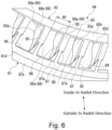
- Fig. 6 is a perspective view of part of the retainer 64 as viewed from outside.
- Fig. 7 is a sectional view along the line VII-VII in Fig. 4 .
- the retainer 64 has an annular large-diameter ring 81, an annular small-diameter ring 82 arranged inside the large-diameter ring 81 in the radial direction, and a plurality of columns 83 connecting the large- and small-diameter rings 81 and 82.
- the large-diameter ring 81, small-diameter ring 82 and columns 83 are integrated together.
- the large-diameter ring 81 is arranged at a distance and outside the outer peripheral surface 66a of the restriction wall 66 of the inner race 62A in the radial direction.
- the large-diameter ring 81 has a large-diameter inner surface 81a (an example of a second side surface recited in the claims), a large-diameter outer surface 81b, an inclined inner surface 81c (an example of the second side surface recited in the claims), an inclined outer surface 81d, an axially outer end surface 81e, and an axially inner end surface 81f.
- the large-diameter inner surface 81a faces in the radial direction the outer peripheral surface 66a of the restriction wall 66.
- the large-diameter outer surface 81b is positioned outside in the radial direction the large-diameter inner surface 81a.
- the inclined inner surface 81c extends from the large-diameter inner surface 81a inward in the axial direction.
- the inclined outer surface 81d extends from the large-diameter outer surface 81b inward in the axial direction.
- the axially outer end surface 81e connects the outer end of the large-diameter inner surface 81a and the outer end of the large-diameter outer surface 81b.
- the axially inner end surface 81f connects the inner end of the inclined inner surface 81c and the inner end of the inclined outer surface 81d.
- the large-diameter inner and outer surfaces 81a and 81b are parallel to the outer peripheral surface 66a of the restriction wall 66.
- the inclined inner and outer surfaces 81c and 81d are inclined with respect to the axial direction such that their axially inner portion is positioned on a more inner side in the radial direction than is their axially outer portion.
- the inclined outer surface 81d is parallel to the axis of roller A3.
- the axially outer end surface 81e is parallel to the radial direction.
- the axially inner end surface 81f is formed such that it is orthogonal to the axis of roller A3.
- the small-diameter ring 82 is arranged at a distance and outside the outer peripheral surface of the retainer placement wall 65 of the inner race 62A in the radial direction.
- the small-diameter ring 82 has a small-diameter inner surface 82a, an axially inner end surface 82b, an inclined inner surface 82c, an inclined outer surface 82d, and an axially outer end surface 82e.
- the small-diameter inner surface 82a faces in the radial direction the outer peripheral surface of the retainer placement wall 65.
- the axially inner end surface 82b extends from the axially inner end of the small-diameter inner surface 82a outward in the axial direction.
- the inclined inner surface 82c extends from the axially outer end of the small-diameter inner surface 82a outward in the axial direction.
- the inclined outer surface 82d extends from the radially outer end of the axially inner end surface 82b outward in the axial direction.
- the axially outer end surface 82e connects the outer end of the inclined inner surface 82c and the outer end of the inclined outer surface 82d.
- the small-diameter inner surface 82a is parallel to the outer peripheral surface of the retainer placement wall 65 and the axial direction.
- the axially inner end surface 82b is parallel to the radial direction.
- the inclined inner and outer surfaces 82c and 82d are inclined with respect to the axial direction such that their axially outer portion is positioned on a more outer side in the radial direction than is their axially inner portion.
- the inclined inner and outer surfaces 82c and 82d are parallel to each other.
- the axially outer end surface 82e is orthogonal to the axis of roller A3. This means that the axially outer end surface 82e is parallel to the axially inner end surface 81f of the large-diameter ring 81.
- the axially outer and inner end surfaces 82e and 81f face each other in the direction along the axis of roller A3.
- the columns 83 extend along the radial direction and arranged at equal intervals in the circumferential direction.
- the columns 83, large-diameter ring 81 and small-diameter ring 82 define pockets 84, where the tapered rollers 63 are rollably housed.
- the columns 83 are each positioned between adjacent two of the tapered rollers 63 in the circumferential direction.
- the columns 83 are shaped like a plate.
- the columns 83 are arranged such that its plate thickness direction coincides with the circumferential direction.
- plate thickness refers to the thickness of the columns 83 in the circumferential direction.
- the columns 83 have a rectangular shape long in the direction extending along the axis of roller A3 when viewed in the circumferential direction.
- the columns 83 each have opposite ends in the direction extending along the axis of roller A3, which are respectively connected to the axially inner end surface 81f of the large-diameter ring 81 and the axially outer end surface 82e of the small-diameter ring 82.
- Each column 83 has an outer surface 85 that is positioned outside in the radial direction.
- the outer surface 85 is a flat surface parallel to the axis of roller A3.
- Each column 83 has an inner surface 86 that is positioned inside in the radial direction.
- the inner surface 86 has a first flat surface 86a, an inclined surface 86b, and a second flat surface 86c, which are arranged in the stated order in the direction from the small-diameter ring 82 to the large-diameter ring 81.
- the first flat surface 86a extends along the axis of roller A3 (along the direction in which the outer surface 85 extends) from the small-diameter ring 82 toward the large-diameter ring 81.
- the inclined surface 86b extends obliquely from the end of the first flat surface 86a facing the large-diameter ring 81 toward the outer surface 85.
- the second flat surface 86c extends from the end of the inclined surface 86b facing the large-diameter ring 81 to the large-diameter ring 81.
- the second flat surface 86c is parallel to the first flat surface 86a, the axis of roller A3 and the outer surface 85.
- the end of the second flat surface 86c facing the large-diameter ring 81 extends over the inclined inner surface 81c.
- the term "shorter axis direction" refers to the direction orthogonal to the axis of roller A3.
- the columns 83 each have a thin portion 87 shaped like a triangle when seen in the circumferential direction at a portion thereof close to the large-diameter ring 81.
- the columns 83 each have side surfaces 83a facing each other in the circumferential direction (hereinafter, referred to as the circumferential side surfaces 83a), and the circumferential side surfaces 83a have a step 87a.
- the thin portion 87 has a smaller plate thickness than defined between the circumferential side surfaces 83a.
- the step 87a extends from the inclined inner surface 81c of the large-diameter ring 81 to the outer surface 85 along the inclined inner surface 81c.
- the columns 83 each have a first fall-out preventing portion 88 in its portion near the outer surface 85.
- the first fall-out preventing portion 88 is configured to prevent the tapered roller 63 from falling out of the retainer 64 in the direction from the inner surface 86 to the outer surface 85 (in a first direction recited in the claims).
- the first fall-out preventing portion 88 protrudes from each circumferential side surface 83a.
- the first fall-out preventing portion 88 extends from the step 87a to the small-diameter ring 82.
- the step 87a is equivalent to a first side surface of the first fall-out preventing portion 88 facing the large-diameter ring 81, which is recited in the claims.
- the first side surface is positioned on the same straight line as the inclined inner surface 81c of the large-diameter ring 81 (a second side surface) (see Fig. 7 ).
- the first fall-out preventing portion 88 extends from a portion that is slightly shifted toward the outer surface 85 from the middle portion in the shorter axis direction to the outer surface 85 and is wider in a portion next to the outer surface 85. Stated differently, the plate thickness of the first fall-out preventing portion 88 gradually increases toward the outer surface 85. Therefore, the first fall-out preventing portion 88 has an inclined surface 88a that is oblique with respect to the circumferential side surface 83a of the column 83.
- the columns 83 each have a second fall-out preventing portion 89 near the inner surface 86.
- the second fall-out preventing portion 89 is configured to prevent the tapered rollers 63 from falling out of the retainer 64 in the direction from the outer surface 85 to the inner surface 86 (in a second direction recited in the claims).
- the second fall-out preventing portion 89 protrudes from each circumferential side surface 83a.
- the second fall-out preventing portion 89 is provided where the first flat surface 86a of the inner surface 86 meets the axially outer end surface 82e of the small-diameter ring 82.
- the second fall-out preventing portion 89 has a triangular shape when viewed in the circumferential direction.
- the plate thickness of the second fall-out preventing portion 89 gradually increases toward the first flat surface 86a and the axially outer end surface 82e. Therefore, the second fall-out preventing portion 89 has an inclined surface 89a that is oblique with respect to the circumferential side surface 83a.
- the first and second fall-out preventing portions 88 and 89 are positioned closer to the small-diameter ring 82 than to the large-diameter ring 81.
- the length L1 of the first fall-out preventing portion 88 denotes the length of the shortest portion of the first fall-out preventing portion 88 in the direction extending along the axis of roller A3. Specifically, the length L1 of the first fall-out preventing portion 88 denotes the length of the end of the first fall-out preventing portion 88 on the outer surface 85 side.
- the length L1 of the first fall-out preventing portion 88 is equal to or greater than 50% of the length L3 indicating the distance between the large-diameter ring 81 and the small-diameter ring 82 (see Fig. 7 ).
- the length L3 of the distance between the large-diameter ring 81 and the small-diameter ring 82 can be also represented as the length of the distance between the axially inner end surface 81f of the large-diameter ring 81 and the axially outer end surface 82e of the small-diameter ring 82.
- the overlap allowance between the width W1 indicating the distance between adjacent two of the first fall-out preventing portions 88 in the circumferential direction (see Fig. 6 ) and the diameter D1 of the small-diameter surface 63b of the tapered rollers 63 (see Fig. 3 ) falls within the range of 5% to 15%.
- the diameter D1 of the small-diameter surface 63b represents the outer diameter of the largest portion of the small-diameter-side rounded portion 63e.
- the thickness Ts defined between the outer surface 85 of the column 83 and the first flat surface 86a (see Fig. 7 ) is 55% to 65% of the diameter D1.
- the thickness T2 defined between the outer surface 85 of the column 83 and the second flat surface 86c (see Fig. 7 ) is 55% to 65% of the thickness Ts.
- the angle ⁇ between the large-diameter inner surface 81a of the large-diameter ring 81 and the inclined inner surface 81c is 5° to 15°, for example.
- the result of subtracting the length L2 from the length L3 is 93% to 99% of the length L4 of the tapered roller 63 in the direction extending along the axis of roller A3 (see Fig. 3 ).
- the length L4 is equal to the result of subtracting the radius R1 of the small-diameter-side rounded portion 63e from the entire length L5 of the tapered roller 63 in the direction extending along the axis of roller A3.
- the width W2 indicating the distance between adjacent two of the second fall-out preventing portions 89 in the circumferential direction is 92% to 97% of the diameter D1.
- the retainer 64 is injection molded using two separable molds 101 and 102 (a first mold 101 and a second mold 102).
- the parting line PL of the two molds 101 and 102 extends along the axially outer end surface 81e, large-diameter inner surface 81a and inclined inner surface 81c of the large-diameter ring 81, the step 87a and outer surface 85 of the columns 83, the inclined outer surface 82d and axially inner end surface 82b of the small-diameter ring 82.
- a direction Y1 indicates the direction in which the two molds 101 and 102 can be separated from each other and denotes the left-right direction in Fig. 7 . Since the parting line PL extends in the above-described manner, the fall-out preventing portions 88 and 89 are made in the first mold 101. In other words, the fall-out preventing portions 88 and 89 are arranged on one of the sides defined with respect to the parting line PL of the molds 101 and 102.
- the tapered rollers 63 are combined with the retainer 64.
- the tapered rollers 63 are combined from the side where the second fall-out preventing portion 89 is positioned, that is to say, from the inside in the radial direction. More specifically, the portion of each tapered roller 63 including the small-diameter surface 63b is inserted between the second and first fall-out preventing portions 89 and 88 of the retainer 64 from the inside in the radial direction, after which the portion of each tapered roller 63 including the large-diameter surface 63a is housed in the pocket 84.
- the first step of combining the portion of the tapered roller 63 including the small-diameter surface 63b with the retainer 64 may involve pushing the portion of the tapered roller 63 including the small-diameter surface 63b into the second fall-out preventing portion 89 from the inside in the radial direction.
- the portion of the tapered roller 63 including the small-diameter surface 63b pushes and expands the second fall-out preventing portion 89 while the tapered roller 63 is being combined.
- the small-diameter surface 63b of the tapered roller 63 has a smaller diameter than the large-diameter surface 63a.
- the second fall-out preventing portion 89 is sufficiently smaller than the first fall-out preventing portion 88. For these reasons, no excessive pressing force is required to combine the tapered roller 63 with the retainer 64.
- the tapered surface 63c of the tapered roller 63 touches the inclined surface 88a of the first fall-out preventing portion 88. This can result in preventing the tapered roller 63 from falling out of the retainer 64 toward the outside in the radial direction.
- the first fall-out preventing portion 88 satisfies the condition described in the above section (2), the tapered roller 63 can be reliably stopped by the first fall-out preventing portion 88. This can result in reliably preventing the tapered roller 63, which is combined with the retainer 64 from the inside in the radial direction, from falling out of the retainer 64 toward the outside in the radial direction.
- the tapered roller 63 While being housed in the pocket 84 of the retainer 64, the tapered roller 63 remains in contact with the inclined surface 88a of the first fall-out preventing portion 88 and also with the inclined surface 89a of the second fall-out preventing portion 89. Accordingly, the second fall-out preventing portion 89 also prevents the tapered roller 63 from falling out of the retainer 64 toward the inside in the radial direction. Having the above-described configuration, the retainer 64 can keep the orientation of the tapered roller 63. In other words, the retainer 64 can retain the tapered roller 63.
- the retainer 64 having the tapered rollers 63 combined is housed between the outer and inner races 61A and 62A. This completes the assembling of the first main bearing 6A.
- a lubricating oil is poured inside the first main bearing 6A.
- the first and second fall-out preventing portions 88 are positioned closer to the small-diameter ring 82 than to the large-diameter ring 81.
- the space S can establish communication between the outside and the inside of the first main bearing 6A in the radial direction. This can improve the oil flowability, thereby allowing the lubricating oil to easily and sufficiently reach the respective parts of the first main bearing 6A.
- the rotational force provided from the external motor (not shown) is transmitted to the crankshafts 4 via the input gear 18 and spur gear 17.
- the first and second oscillating gears 5A and 5B which support the crankshafts 4, oscillatorily rotate.
- the carrier 3 rotating on the axis of rotation A1 at the reduced speed when compared with the rotation produced by the external motor.
- the main bearings 6A and 6B Via the main bearings 6A and 6B, the carrier 3 rotates relative to the outer tube 2.
- the carrier 3 serves as an output unit for outputting the rotation input into the speed reducer 1 (the rotation produced by the external motor).
- a not-shown drive member can be driven by being attached to the carrier 3.
- the outer tube 2 serves as an output unit for outputting the rotation input into the speed reducer 1 (the rotation produced by the external motor).
- a not-shown drive member can be driven by being attached to the outer tube 2.
- the outer tube 2 and carrier 3 can both serve as an output unit (first and second output units recited in the claims).
- the retainer 64 of the main bearings 6A and 6B has the two types of fall-out preventing portions 88 and 89.
- the first fall-out preventing portion 88 can prevent the tapered roller 63 from falling out of the retainer 64 toward the outside in the radial direction.
- the second fall-out preventing portion 89 can prevent the tapered roller 63 from falling out of the retainer 64 toward the inside in the radial direction. Consequently, the main bearings 6A and 6B can be assembled in an improved manner. For example, if the retainer 64 has only one type of fall-out preventing portions, the tapered rollers 63 could fall out of the retainer 64 toward the outside or inside in the radial direction. This will obstruct the assembling of the main bearings 6A and 6B.
- Each column 83 has the two types of fall-out preventing portions 88 and 89 positioned closer to the small-diameter ring 82 than to the large-diameter ring 81. This leaves, on the large-diameter ring 81 side, the fully open space S (see Fig. 2 ) between the large-diameter ring 81 and the small-diameter ring 82. This can improve the flowability of the oil into the inside of the main bearings 6A and 6B. As a result, the main bearings 6A and 6B can achieve an extended product lifetime.
- the space S can be left on the large-diameter ring 81 side.
- the large-diameter ring 81 has a longer circumferential length than the small-diameter ring 82.
- the space S can have a larger opening area than when left on the small-diameter ring 82 side.
- the tapered rollers 63 which are used as the rolling elements of the main bearings 6A and 6B, are arranged such that the small-diameter surface 63b faces the small-diameter ring 82 of the retainer 64.
- the small-diameter surface 63b of the tapered rollers 63 are positioned on the small-diameter ring 82 side, where the two types of fall-out preventing portions 88 and 89 are arranged.
- the rolling elements can be combined with the retainer 64 in a more facilitated manner than in a case where the portion of the tapered roller 63 including the large-diameter surface 63a is placed where the fall-out preventing portions 88 and 89 are provided.
- the length L1 of the first fall-out preventing portion 88 is different from the length L2 of the second fall-out preventing portion 89.
- the tapered rollers 63 can be combined with the retainer 64 more easily as the tapered rollers 63 are combined with the retainer 64 from the side where the shorter fall-out preventing portion is provided.
- the different lengths L1 and L2 can result in a more reliable oil flow space (space S).
- the tapered rollers 63 can be combined with the retainer 64 from the inside in the radial direction in a smoother way.
- the tapered rollers 63 may accidentally fall out of the retainer 64 toward the outside in the radial direction. This can be reliably prevented from happening since the length L1 of the first fall-out preventing portion 88 is greater than the length L2 of the second fall-out preventing portion 89.
- the length L1 of the first fall-out preventing portion 88 satisfies the relation described in the above section (2). Accordingly, the inclined surface 88a of the first fall-out preventing portion 88 can reliably butt up against the tapered surface 63c of the tapered roller 63.
- the tapered rollers 63 When the tapered rollers 63 are assembled into the retainer 64 from the inside in the radial direction, the tapered rollers 63 may accidentally fall out of the retainer 64 toward the outside in the radial direction. This can be more reliably prevented from happening. The retainer 64 can thus reliably retain the tapered roller 63.
- the thickness T1 of the large-diameter ring 81 in the radial direction and the thickness T2 indicating the distance between the outer surface 85 of the column 83 and the second flat surface 86c satisfies the relation described in the above section (6), i.e., the expression (1).
- the large-diameter ring 81 is arranged at a distance and outside the outer peripheral surface 66a of the restriction wall 66 of the inner race 62A in the radial direction.
- the large-diameter ring 81 needs to be configured such that it can avoid interfering with the restriction wall 66.
- draft should be applied to the parts of the retainer 64, which is injection molded using the two molds 101 and 102. Considering these issues, the thickness T1 of the large-diameter ring 81 in the radial direction is preferably small.
- the first mold 101 could be more easily removed from the retainer 64 if the large-diameter inner surface 81a is inclined with respect to the axis of roller A3 so that it can extend along the inclined inner surface 81c of the large-diameter ring 81.
- a small thickness T1 can help the large-diameter ring 81 avoiding the interference with the restriction wall 66.
- the angle ⁇ formed between the large-diameter inner surface 81a of the large-diameter ring 81 and the inclined inner surface 81c is preferably 5° to 15°.
- the two molds 101 and 102 are used, of which the first mold 101 can shape the fall-out preventing portions 88 and 89.
- the fall-out preventing portions 88 and 89 are positioned on one of the sides defined with respect to the parting line PL for the molds 101 and 102.
- the method of manufacturing the retainer 64 uses only the first mold 101 to shape the fall-out preventing portions 88 and 89. Therefore, the accuracy of molding the fall-out preventing portions 88 and 89 solely depends on the first mold 101. If a change is made in the shape of the fall-out preventing portions 88 and 89, it is only the first mold 101 that needs to be changed. Accordingly, the present embodiment can reduce the manufacturing cost.
- the step 87a of the first fall-out preventing portion 88 (the first side surface) is located on the same straight line as the inclined inner surface 81c of the large-diameter ring 81 (second side surface).
- the parting line PL for the molds 101 and 102 can extend along the step 87a, the inclined inner surface 81c and part of the outer surface 85 of the column 83 (the portion of the outer surface 85 that is positioned closer to the small-diameter ring 82 with respect to the step 87a). Since the parting line PL is configured in the above-described manner, the fall-out preventing portions 88 and 89 can be made only with the first mold 101.
- the speed reducer 1 can be assembled in an improved manner as constituted by the above-described main bearings 6A and 6B. Additionally, the speed reducer 1 can achieve an extended product lifetime.
- each column 83 has the two fall-out preventing portions 88 and 89 positioned closer to the small-diameter ring 82 than to the large-diameter ring 81.
- the present embodiment is not limited to such.
- Each column 83 may have the two fall-out preventing portions 88 and 89 positioned closer to the large-diameter ring 81 than to the small-diameter ring 82. Even in this case, an open space can be left between the large- and small-diameter rings 81 and 82.
- the length L1 of the first fall-out preventing portion 88 and the length L2 of the second fall-out preventing portion 89 satisfy the relation described in the above section (1).
- the present embodiment is not limited to such, and the lengths L1 and L2 just need to be different from each other. Consequently, the main bearings 6A and 6B can achieve improved oil flowability.
- the main bearings 6A and 6B are tapered roller bearings, where the tapered rollers 63 are used as the rolling elements.
- the present embodiment is not limited to such, and the above-described retainer 64 can be applicable to various types of bearings.
- the above-described retainer 64 can be applicable to cages for retaining as rolling elements cylindrical or spherical rollers.
- the parts of the retainer 64 have dimensions determined to satisfy the relations described in the sections (1) to (8).
- the present embodiment is not limited to such, and the parts of the retainer 64 do not need to have dimensions satisfying the relations described in the sections (1) to (8).
- the retainer 64 is at least required to have the two types of fall-out preventing portions 88 and 89, which are positioned closer to one of the large-diameter ring 81 or the small-diameter ring 82 than to the other.
- the columns 83 each have the outer and inner surfaces 85 and 86.
- the inner surface 86 is divided into the first flat surface 86a, inclined surface 86b and second flat surface 86c.
- the parting line PL for the two molds 101 and 102 extends along the axially outer end surface 81e, large-diameter inner surface 81a, and inclined inner surface 81c of the large-diameter ring 81, the step 87a and outer surface 85 of each column 83, the inclined outer surface 82d and axially inner end surface 82b of the small-diameter ring 82.
- the present embodiment is not limited to such, and the columns 83 can be shaped in any manners.
- the parting line PL can be set depending on the shape of the columns 83. Note that, however, the parting line PL is preferably determined such that the fall-out preventing portions 88 and 89 can be made using one of the two molds 101 and 102.
- the speed reducer 1 is an eccentric oscillation speed reducer including the crankshafts 4, oscillating gears 5A and 5B, and the like.
- the speed reducer 1 has the main bearings 6A and 6B.
- the present embodiment is not limited to such, and the main bearings 6A and 6B can be applicable to various types of speed reducers 1.
- the main bearings 6A and 6B can be applicable to any other devices than the speed reducer 1.
- the main bearings 6A and 6B can be applicable not only to devices for reducing input rotation (speed reducers) but also to devices for increasing input rotation.
Landscapes
- Engineering & Computer Science (AREA)
- General Engineering & Computer Science (AREA)
- Mechanical Engineering (AREA)
- Manufacturing & Machinery (AREA)
- Ocean & Marine Engineering (AREA)
- Rolling Contact Bearings (AREA)
- Retarders (AREA)
Abstract
A retainer (64) relating to an embodiment of the present invention includes a large-diameter ring (81), a small-diameter ring (82), and a plurality of columns (83) connecting the large- and small-diameter rings (81 and 82). The columns (83) each have a first fall-out preventing portion (88) and a second fall-out preventing portion (89). The first fall-out preventing portion (88) is configured to prevent tapered rollers (63) from falling out of the large- and small-diameter rings (81 and 82) toward the outside in the radial direction, and the second fall-out preventing portion (89) is configured to prevent the tapered rollers (63) from falling out of the large- and small-diameter rings (81 and 82) to the inside in the radial direction. The fall-out preventing portions (88 and 89) are positioned closer to the small-diameter ring (82) than to the large-diameter ring (81).
Description
- The present invention relates to a cage, a bearing, a transmission, and a method of manufacturing a cage.
- In the conventional art, cages are known to retain rolling elements (rollers) of roller bearings. Cages are produced by injection molding, for example. A retainer retains a plurality of rollers at equal intervals in the circumferential direction. For example, a retainer used in a tapered roller bearing has an annular large-diameter ring, an annular small-diameter ring having a smaller outer diameter than the large-diameter ring, and a plurality of columns extending in the radial direction to connect the large- and small-diameter rings. The columns are arranged at equal intervals in the circumferential direction. The large-diameter ring, small-diameter ring, and columns define pockets, where tapered rollers are housed.
- In order to improve the manner of assembling bearings of the type described above, a technology is disclosed where the columns have a conical surface for the purpose of preventing the rolling elements from falling out of the retainer (see, for example, Patent Literature 1). The conical surfaces of the columns are arranged such that one conical surface is positioned on either side defined with respect to the axis of each tapered roller (rolling element). Stated differently, each column has two conical surfaces. The conical surfaces protrude toward the direction in which the column faces the adjacent columns in the circumferential direction. The conical surfaces are in contact with the outer surface of the tapered rollers. This can prevent the tapered rollers from falling out of the cage.
- One of the two conical surfaces extends between (i) the middle point between the large- and small-diameter rings and (ii) the large-diameter ring. The other of the two conical surfaces extends between (i) the middle point between the large- and small-diameter rings and (ii) the small-diameter ring. This configuration can prevent the rollers from falling out of the retainer either outwardly or inwardly while allowing the retainer to be shaped by means of injection molding.
- Patent Literature 1:
Japanese Patent Application Publication No. 2014-202284 - According to the conventional technology described above, when the bearing is viewed in the axial direction, the conical surfaces extend over the entire area between the large- and small-diameter rings. In other words, the conical surfaces extend over the entire radial length of the columns. Therefore, the conical surfaces may obstruct the flow of lubricating oil through the bearing from the outside to the inside (hereinafter referred to as "oil flowability"), which could lead to failures of the bearing. This may result in a shorter product lifetime of the bearing.
- The present invention provides a cage, a bearing, a transmission, and a method of manufacturing a retainer that can provide an improved manner of assembling and achieve an extended product lifetime by preventing the rolling elements from falling out.
- One aspect of the present invention provides a retainer for retaining a plurality of rolling elements of a bearing. The retainer includes an annular large-diameter ring; an annular small-diameter ring having a smaller outer diameter than the large-diameter ring; and a plurality of columns extending in a radial direction of the large- and small-diameter rings to connect the large- and small-diameter rings. The columns are arranged at equal intervals in a circumferential direction and between the rolling elements. The columns each have: a first fall-out preventing portion for preventing the rolling elements from falling out of the large- and small-diameter rings toward a first direction; and a second fall-out preventing portion for preventing the rolling elements from falling out of the large- and small-diameter rings toward a second direction opposite to the first direction. The first and second fall-out preventing portions are positioned closer to one of the large-diameter ring or the small-diameter ring than to another of the large-diameter ring or the small-diameter ring.
- In this way, the two fall-out preventing portions can prevent the rolling elements from falling out of the cage, thereby improving the manner of assembling the bearing. The two fall-out preventing portions are positioned closer to one of the large-diameter ring or the small-diameter ring than to the other of the large-diameter ring or the small-diameter ring. Therefore, a fully open space is left between the large-diameter ring and the small-diameter ring on the other side than where the fall-out preventing portions are provided. This can lead to improvement of oil flowability, thereby allowing the bearing to have an extended product lifetime.
- In the implementation, the first and second fall-out preventing portions may be positioned closer to the small-diameter ring than to the large-diameter ring.
- In the implementation, the rolling elements may include tapered rollers.
- In the implementation, a length L1 of the first fall-out preventing portion in a direction orthogonal to the first and second directions may be different from a length L2 of the second fall-out preventing portion in a direction orthogonal to the first and second directions.
- In the implementation, the first fall-out preventing portion may be positioned outside in the radial direction. The second fall-out preventing portion may be positioned inside in the radial direction. The length L2 of the second fall-out preventing portion may be measured in a direction in which an axis of the tapered rollers extends. The length L1 of the first fall-out preventing portion may be measured in the direction in which the axis of the tapered rollers extends. The length L2 of the second fall-out preventing portion may be less than the length L1 of the first fall-out preventing portion.
- In the implementation, the length L1 of the first fall-out preventing portion may be equal to or greater than 50% of a length L3 indicating a distance between the large- and small-diameter rings.
- In the implementation, the columns each have: an outer surface located outside in the radial direction; and an inner surface located inside in the radial direction. The outer surface is a flat surface extending from the small-diameter ring to the large-diameter ring. The inner surface has: a first flat surface extending from the small-diameter ring toward the large-diameter ring in a direction in which the outer surface extends; an inclined surface extending obliquely from an end of the first flat surface facing the large-diameter ring toward the outer surface; and a second flat surface extending from an end of the inclined surface facing the large-diameter ring to the large-diameter ring in the direction in which the outer surface extends. A relation of T1 ≥ T2 may be satisfied, where T1 represents a thickness in the radial direction of an end of the large-diameter ring that faces away from the small-diameter ring and T2 represents a thickness indicating a distance between the outer surface and the second flat surface.
- In the implementation, the large-diameter ring, the small-diameter ring and the columns may be made from a resin and shaped by two separable molds. The first and second fall-out preventing portions may be both located on one of sides defined with respect to a parting line for the two separable molds.
- In the implementation, a first side surface of the first fall-out preventing portion that faces the large-diameter ring may be located on a same straight line as a second side surface of the large-diameter ring that faces inside in the radial direction. The first side surface, the second side surface and a portion of the outer surface of the each column that is positioned on the small-diameter ring side with respect to the first side surface may be arranged along the parting line.
- Another aspect of the present invention provides a bearing including an outer race; an inner race located inside the outer race in a radial direction; a plurality of rolling elements rollably housed between the inner race and the outer race; and a retainer retaining the plurality of rolling elements. The retainer includes: an annular large-diameter ring; an annular small-diameter ring having a smaller outer diameter than the large-diameter ring; and a plurality of columns connecting the large- and small-diameter rings, the columns being arranged at equal intervals in a circumferential direction and between the rolling elements. The columns each have: a first fall-out preventing portion for preventing the rolling elements from falling out of the large- and small-diameter rings toward a first direction; and a second fall-out preventing portion for preventing the rolling elements from falling out of the large- and small-diameter rings toward a second direction opposite to the first direction. The first and second fall-out preventing portions are positioned closer to one of the large-diameter ring or the small-diameter ring than to another of the large-diameter ring or the small-diameter ring.
- In this way, the two types of fall-out preventing portions can prevent the rolling elements from falling out of the cage, thereby improving the manner of assembling the bearing. The two types of fall-out preventing portions are positioned closer to one of the large-diameter ring or the small-diameter ring than to the other of the large-diameter ring or the small-diameter ring. Therefore, a fully open space is left between the large-diameter ring and the small-diameter ring on the other side than where the fall-out preventing portions are provided. This can lead to improvement of oil flowability of the bearing, thereby allowing the bearing to have an extended product lifetime.
- Another aspect of the present invention provides a transmission including an input part for receiving an input rotational force; a speed changing unit for changing a speed of rotation of the input part; a first output part and a second output part to which the rotation of the input part is transmitted via the speed changing unit, the first and second output parts being configured to rotate relative to each other; and a bearing supporting the first and second output parts such that the first and second output parts are rotatable relative to each other. The bearing includes: an outer race; an inner race located inside the outer race in a radial direction; a plurality of rolling elements reliably housed between the inner race and the outer race; and a retainer retaining the plurality of rolling elements. The retainer includes: an annular large-diameter ring; an annular small-diameter ring having a smaller outer diameter than the large-diameter ring; and a plurality of columns connecting the large- and small-diameter rings, the columns being arranged at equal intervals in a circumferential direction and between the rolling elements. The columns each have: a first fall-out preventing portion for preventing the rolling elements from falling out of the large- and small-diameter rings toward a first direction; and a second fall-out preventing portion for preventing the rolling elements from falling out of the large- and small-diameter rings toward a second direction opposite to the first direction. The first and second fall-out preventing portions are positioned closer to one of the large-diameter ring or the small-diameter ring than to another of the large-diameter ring or the small-diameter ring.
- In this manner, the bearing can be assembled in an improved manner, so that the transmission can be also assembled in an improved manner. As the bearing can achieve improved oil flowability, thereby allowing the transmission to have an extended product lifetime.
- Another aspect of the present invention provides a method of manufacturing a retainer for retaining a plurality of rolling elements of a bearing. The retainer has a first fall-out preventing portion for preventing the rolling elements from falling out of the retainer toward a first direction and a second fall-out preventing portion for preventing the rolling elements from falling out of the retainer toward a second direction opposite to the first direction, the first fall-out preventing portion being positioned on one of sides defined relative to the rolling element and the second fall-out preventing portion being positioned on said one of sides defined relative to the rolling elements. The method includes steps of: making the retainer from a resin by means of injection molding using two molds; and separating the two molds from each other at a parting line. One of the two molds is used to make the first and second fall-out preventing portions.
- This method can produce a retainer having rolling elements in such a manner that the rolling elements can be prevented from falling out. Therefore, the method can contribute to improve the manner of assembling a bearing. Since the first and second fall-out preventing portions are positioned on the same side defined relative to the rolling elements, the bearing can accomplish improved oil flowability and an extended product lifetime. Since the two fall-out preventing portions are collectively shaped using a single mold, the molding accuracy of the fall-out preventing portions can be readily adjusted, and the retainer can be manufactured at a reduced cost.
- The present invention can provide an improved manner of assembling a bearing and achieve an extended product lifetime by preventing the rolling elements from falling out.
-
-
Fig. 1 is a sectional view of a speed reducer according to an embodiment of the present invention. -
Fig. 2 is an enlarged view of the part II ofFig. 1 . -
Fig. 3 is a side view of a tapered roller according to the embodiment of the invention. -
Fig. 4 is a side view of a retainer according to the embodiment of the present invention. -
Fig. 5 is a perspective view of part of the retainer according to the embodiment of the present invention as viewed from outside. -
Fig. 6 is a perspective view of part of the retainer according to the embodiment of the present invention as viewed from inside. -
Fig. 7 is a sectional view along the line VII-VII inFig. 4 . - The embodiments of the present invention will be hereinafter described with reference to the drawings.
-
Fig. 1 is a sectional view of aspeed reducer 1.Fig. 1 only presents one of the halves (the upper half) of thespeed reducer 1 divided by an axis of rotation A1 of a carrier 3. As shown inFig. 1 , thespeed reducer 1 includes a circular cylindricalouter tube 2, a carrier 3 rotatably supported on theouter tube 2 via twomain bearings main bearing 6A and a secondmain bearing 6B) and areduction unit 10 provided on the carrier 3. In the following description, the term "axial direction" refers to the direction parallel to the axis of rotation A1. The term "circumferential direction" refers to the rotational direction of the carrier 3. The term "radial direction" refers to the radial direction of the carrier 3, which is orthogonal to the axial and circumferential directions. In the following description, the expression "inside in the axial direction" refers to the side closer to the center of theouter tube 2 in the axial direction, and the expression "outside in the axial direction" refers to the side facing away from the center of theouter tube 2 in the axial direction. - The central axis of the
outer tube 2 coincides with the axis of rotation A1. The inner circumferential surface of theouter tube 2 has aninternal tooth portion 21 in its middle portion in the axial direction. The part indicated by the term "middle portion" includes the middle between the opposite ends of theouter tube 2 in the axial direction and also the vicinity of the middle. Theinternal tooth portion 21 has a plurality ofpin grooves 21a. Thepin grooves 21a extend in the axial direction and are provided at equal intervals in the circumferential direction. Thepin grooves 21a respectively receive internal tooth pins 25 therein. The internal tooth pins 25 are shaped like a circular column. The internal tooth pins 25 serve as internal teeth and constitute part of thereduction unit 10. - The inner circumferential surface of the
outer tube 2 also has first and second outerrace holding portions 22 and 23 sandwiching theinternal tooth portion 21 respectively via step surfaces 26 and 27. The first outerrace holding portion 22 fittedly receives anouter race 61A of the firstmain bearing 6A of the twomain bearings outer race 61B of the secondmain bearing 6B of the twomain bearings outer races outer races - The second outer race holding portion 23 is positioned at one of the ends of the
outer tube 2 in the axial direction. The inner circumferential surface of theouter tube 2 has aseal portion 24 continuous from the first outerrace holding portion 22 via astep surface 28. Theseal portion 24 and theinternal tooth portion 21 sandwich the first outerrace holding portion 22. Theseal portion 24 is positioned at the other end of theouter tube 2 in the axial direction. Theseal portion 24 has a greater inner diameter than the first outerrace holding portion 22. Theseal portion 24 fittedly receives anoil seal 11. Theoil seal 11 provides sealing between theouter tube 2 and the carrier 3. - The carrier 3 is constituted by first and second carrier blocks 30 and 50, so that it can be divided into portions arranged next to each other in the axial direction. The
first carrier block 30 is positioned near the firstmain bearing 6A. Thefirst carrier block 30 includes abase 31 and a plurality of support columns (not shown). Thebase 31 has a disk-like shape, and the plurality of support columns extend from the base 31 toward thesecond carrier block 50. A portion of the outer circumferential surface of the base 31 that faces outward in the axial direction (that faces away from the second carrier block 50) constitutes aseal portion 34. Theseal portion 34 fittedly receives theoil seal 11. In this way, theoil seal 11 provides sealing between theouter tube 2 and the carrier 3. - The
base 31 has a first innerrace holding portion 33 continuous from theseal portion 34 via astep surface 35. The first innerrace holding portion 33 is positioned inside theseal portion 34 in the axial direction. The first innerrace holding portion 33 has a smaller outer diameter than theseal portion 34. The first innerrace holding portion 33 fittedly receives aninner race 62A of the firstmain bearing 6A. In this manner, thefirst carrier block 30 is rotatably supported by theouter tube 2. Theinner race 62A butts up against thestep surface 35, which can rightly position theinner race 62A in the axial direction. - The
base 31 has a plurality of firstshaft mounting holes 41, which are arranged inside the first innerrace holding portion 33 in the radial direction. The firstshaft mounting holes 41 extend through the base 31 in the axial direction. The firstshaft mounting holes 41 are arranged at equal intervals in the circumferential direction. The firstshaft mounting holes 41 receive therein crankshafts 4 constituting part of thereduction unit 10. The crankshafts 4 will be described below. - Each first
shaft mounting hole 41 is divided into a firstshaft supporting portion 42, an increaseddiameter portion 44, abush holding portion 43 and a communicatingportion 45 that are positioned in the stated order from the inside in the axial direction. The increaseddiameter portion 44 has a greater inner diameter than the firstshaft supporting portion 42. Thebush holding portion 43 has a smaller inner diameter than the firstshaft holding portion 42. The communicatingportion 45 has a smaller inner diameter than thebush holding portion 43. - The
bush holding portion 43 fittedly receives abush 15. Thebush 15 restricts the crankshaft 4 (described below) from moving in the axial direction. The firstshaft supporting portion 42 fittedly receives a first crank bearing 7A. The first crank bearing 7A can help the crankshafts 4 (described below) being rotatably supported by thefirst carrier block 30. The communicatingportion 45 has aseal cap 12 mounted from the outside in the axial direction. - Although not shown, the support columns are each positioned between adjacent two of the first
shaft mounting holes 41 in the circumferential direction. The support columns each have an end surface facing thesecond carrier block 50, which butts up against thesecond carrier block 50. - The
second carrier block 50 is positioned near the secondmain bearing 6B. Thesecond carrier block 50 is secured by bolts (not shown) while butting up against the support columns (not shown) of thefirst carrier block 30. In other words, thesecond carrier block 50 is spaced away from thefirst carrier block 30 with a distance equal to the height of the support columns in the axial direction being provided therebetween. The first and second carrier blocks 30 and 50 are integrated together. - The
second carrier block 50 is shaped like a circular plate. A portion of the outer surface of thesecond carrier block 50 that faces inward in the axial direction (that faces the first carrier block 30) has a second innerrace holding portion 52 continuous from astep surface 53. The second innerrace holding portion 52 has a smaller outer diameter than the axially outer portion of thesecond carrier block 50. The second innerrace holding portion 52 fittedly receives aninner race 62B of the secondmain bearing 6B. In this manner, thesecond carrier block 50 is rotatably supported by theouter tube 2. Theinner race 62B is rightly positioned in the axial direction by thestep surface 53. - The
second carrier block 50 has a plurality of secondshaft mounting holes 54, which are arranged inside the second innerrace holding portion 52 in the radial direction. The number of secondshaft mounting holes 54 is the same as the number of first shaft mounting holes 41. The secondshaft mounting holes 54 extend through thesecond carrier block 50 in the axial direction. Each of the secondshaft mounting holes 54 is coaxially arranged with a corresponding one of the first shaft mounting holes 41. The secondshaft mounting holes 54 receive therein the crankshafts 4, which will be described below. Each secondshaft mounting hole 54 is divided into a secondshaft supporting portion 55 and an internally threadedportion 56 that are positioned in the stated order from the inside in the axial direction. - The effective diameter of the internally threaded
portion 56 is greater than the inner diameter of the secondshaft supporting portion 55. The secondshaft supporting portion 55 fittedly receives a second crank bearing 7B. The second crank bearing 7B can help the crankshafts 4 (described below) being rotatably supported by thesecond carrier block 50. An annular fall-out preventingbolt 16 is screwed into the internally threadedportion 56. The fall-out preventingbolt 16 prevents the crankshafts 4 from falling out of the second haft mounting holes 54. - The
reduction unit 10 is an eccentric oscillation speed reducing mechanism. More specifically, thereduction unit 10 is mainly constituted by the internal tooth pins 25, the crankshafts 4 inserted through theshaft mounting holes oscillating gears oscillating gear 5A and a secondoscillating gear 5B) rotatably mounted on the crankshafts 4. The crankshafts 4 each have afirst journal 71 having the first crank bearing 7A fitted thereon, asecond journal 72 having the second crank bearing 7B fitted thereon, twoeccentric portions 73 and 74 (a firsteccentric portion 73 and a second eccentric portion 74) positioned inside thejournals diameter portion 75 protruding from thesecond journal 72 outward in the axial direction. - The
bush 15 is provided outside thefirst journal 71 in the axial direction. The fall-out preventingbolt 16 is provided outside thesecond journal 72 in the axial direction. This results in restricting the crankshaft 4 from moving in the axial direction relative to the carrier 3. Among the twoeccentric portions 73 and 74, the firsteccentric portion 73 is arranged next to thefirst journal 71. Among the twoeccentric portions 73 and 74, the second eccentric portion 74 is arranged next to thesecond journal 72. The centers of theeccentric portions 73 and 74 are shifted from the axis of rotation A2 of the crankshaft 4. The axis of rotation A2 is parallel to the axis of rotation A1 (the axial direction). Theeccentric portions 73 and 74 are disposed so as to have a phase difference of a predetermined angle (180 ° in the embodiment) from each other. - The reduced
diameter portion 75 extends outward in the axial direction beyond thesecond carrier block 50 through the fall-out preventingbolt 16. Aspur gear 17 is mounted at, for example, the outer portion of the reduceddiameter portion 75 beyond thesecond carrier block 50. Thespur gear 17 meshes with aninput gear 18 that receives rotation input from an external motor, which is not shown. This allows the rotational force provided from the external motor (the rotational force of the input gear 18) to be transmitted to the crankshaft 4 via thespur gear 17. - The two
oscillating gears second carrier block 50 and thebase 31 of thefirst carrier block 30. The twooscillating gears second carrier block 50 and thebase 31. Among the twooscillating gears oscillating gear 5A is positioned closer to thebase 31. Among the twooscillating gears oscillating gear 5B is positioned closer to thesecond carrier block 50. - The two
oscillating gears external teeth 77 on the outer periphery, which mesh with the internal tooth pins 25 provided on theouter tube 2. The twooscillating gears oscillating gear 5A, the firsteccentric portions 73 are provided via firsteccentric bearings 8A. In the shaft insertion holes 78 of the secondoscillating gear 5B, the second eccentric portions 74 are provided via secondeccentric bearings 8B. - With the above-described arrangements, as the crankshafts 4 rotate and the first
eccentric portions 73 eccentrically rotate, the eccentric rotation of the firsteccentric portions 73 results in the firstoscillating gear 5A oscillatorily rotating about the axis of rotation A2 while meshing with some of the internal tooth pins 25. As the crankshafts 4 rotate and the second eccentric portions 74 eccentrically rotate, the eccentric rotation of the second eccentric portions 74 results in the secondoscillating gear 5B oscillatorily rotating about the axis of rotation A2 while meshing with some of the internal tooth pins 25. As a result, the crankshafts 4 supported by the first and second oscillating gears 5A and 5B orbit around the axis of rotation A1, and the carrier 3 supporting the crankshafts 4 rotates about the axis of rotation A1. - The following now describes the
main bearings main bearings main bearing 6A of the twomain bearings main bearing 6B is not described here.Fig. 2 is an enlarged view of the part II ofFig. 1 . As shown inFig. 2 , the firstmain bearing 6A is a tapered roller bearing. The firstmain bearing 6A includes anouter race 61A fitted on theouter tube 2, aninner race 62A fitted onto the carrier 3, a plurality of taperedrollers 63 housed between the outer andinner races resin retainer 64 housed between the outer andinner races rollers 63. InFig. 1 , among the components of the secondmain bearing 6B, the tapered rollers and retainer are identified by the same reference numerals as those assigned to the corresponding components of the firstmain bearing 6A. - The
outer race 61A has a triangular cross-section when cut along the axial direction. More specifically, theouter race 61A has an outercircumferential surface 61a butting up against the first outerrace holding portion 22 of theouter tube 2, anend surface 61b butting up against thestep surface 26, and anouter rolling surface 61c facing inward in the radial direction. Theouter rolling surface 61c is inclined with respect to the axial direction such that its axially inner portion is positioned on a more inner side in the radial direction than is its axially outer portion. - The
inner race 62A has a triangular cross-section when cut along the axial direction. More specifically, theinner race 62A has an innercircumferential surface 62a butting up against the first innerrace holding portion 33 of thefirst carrier block 30, anend surface 62b butting up against thestep surface 35, and aninner rolling surface 62c facing outward in the radial direction. Theinner rolling surface 62c is inclined with respect to the axial direction such that its axially inner portion is positioned on a more inner side in the radial direction than is its axially outer portion. - The
inner race 62A has aretainer placement wall 65 integrated together, which is shaped like a circular cylinder. Theretainer placement wall 65 protrudes from the axially inner portion of theinner rolling surface 62c inwardly in the axial direction. On theretainer placement wall 65, part of theretainer 64 is placed. Theinner race 62A further has anannular restriction wall 66 integrated together. Therestriction wall 66 projects from the axially outer portion of theinner rolling surface 62c outwardly in the radial direction. Therestriction wall 66 can rightly position the taperedrollers 63 in the axial direction. - The outer
peripheral surface 66a of therestriction wall 66 extends along the axial direction. Therestriction wall 66 has arestriction surface 66b rising from the axially outer portion of theinner rolling surface 62c. Therestriction surface 66b is orthogonal to theinner rolling surface 62c. Since the outerperipheral surface 66a andrestriction surface 66b are configured in this way, therestriction wall 66 is inwardly tapered in the axial direction. As the end surface of the taperedrollers 63 in the axial direction butts up against therestriction surface 66b, the taperedrollers 63 are rightly positioned. -
Fig. 3 is a side view of the taperedrollers 63. As shown inFigs. 2 and3 , the taperedrollers 63 are shaped like a circular truncated cone centered on an axis of roller A3. The taperedrollers 63 each have a large-diameter surface 63a, a small-diameter surface 63b, and ataper surface 63c connecting the large- and small-diameter surfaces taper surface 63c is inclined with respect to the axis of roller A3 such that the distance between thetaper surface 63c and the axis of roller A3 is greater at the large-diameter surface 63a than at the small-diameter surface 63b. A large-diameter-siderounded portion 63d is formed where the large-diameter surface 63a and thetaper surface 63c meets. A small-diameter-siderounded portion 63e is formed where the small-diameter surface 63b and thetaper surface 63c meets. - The tapered
rollers 63 are each inclined with respect to the axial and radial directions such that the axially inner portion of the axis of roller A3 is positioned on a more inner side in the radial direction than is the axially outer portion of the axis of roller A3. The taperedrollers 63 are arranged such that its small-diameter surface 63b face inward in the radial direction. The taperedrollers 63 orbit around the axis of rotation A1 while rolling on the outer and inner rolling surfaces 61c and 62c. The taperedrollers 63 are arranged at equal intervals in the circumferential direction by theretainer 64. -
Fig. 4 is a side view of theretainer 64.Fig. 5 is a perspective view of part of theretainer 64 as viewed from outside.Fig. 6 is a perspective view of part of theretainer 64 as viewed from outside.Fig. 7 is a sectional view along the line VII-VII inFig. 4 . As shown inFigs. 1 ,2 , and4 to 7 , theretainer 64 has an annular large-diameter ring 81, an annular small-diameter ring 82 arranged inside the large-diameter ring 81 in the radial direction, and a plurality ofcolumns 83 connecting the large- and small-diameter rings 81 and 82. The large-diameter ring 81, small-diameter ring 82 andcolumns 83 are integrated together. - The large-
diameter ring 81 is arranged at a distance and outside the outerperipheral surface 66a of therestriction wall 66 of theinner race 62A in the radial direction. The large-diameter ring 81 has a large-diameterinner surface 81a (an example of a second side surface recited in the claims), a large-diameterouter surface 81b, an inclinedinner surface 81c (an example of the second side surface recited in the claims), an inclinedouter surface 81d, an axiallyouter end surface 81e, and an axiallyinner end surface 81f. The large-diameterinner surface 81a faces in the radial direction the outerperipheral surface 66a of therestriction wall 66. The large-diameterouter surface 81b is positioned outside in the radial direction the large-diameterinner surface 81a. The inclinedinner surface 81c extends from the large-diameterinner surface 81a inward in the axial direction. The inclinedouter surface 81d extends from the large-diameterouter surface 81b inward in the axial direction. The axiallyouter end surface 81e connects the outer end of the large-diameterinner surface 81a and the outer end of the large-diameterouter surface 81b. The axiallyinner end surface 81f connects the inner end of the inclinedinner surface 81c and the inner end of the inclinedouter surface 81d. - The large-diameter inner and
outer surfaces peripheral surface 66a of therestriction wall 66. The inclined inner andouter surfaces outer surface 81d is parallel to the axis of roller A3. The axiallyouter end surface 81e is parallel to the radial direction. The axiallyinner end surface 81f is formed such that it is orthogonal to the axis of roller A3. - The small-
diameter ring 82 is arranged at a distance and outside the outer peripheral surface of theretainer placement wall 65 of theinner race 62A in the radial direction. The small-diameter ring 82 has a small-diameterinner surface 82a, an axiallyinner end surface 82b, an inclinedinner surface 82c, an inclinedouter surface 82d, and an axiallyouter end surface 82e. The small-diameterinner surface 82a faces in the radial direction the outer peripheral surface of theretainer placement wall 65. The axiallyinner end surface 82b extends from the axially inner end of the small-diameterinner surface 82a outward in the axial direction. The inclinedinner surface 82c extends from the axially outer end of the small-diameterinner surface 82a outward in the axial direction. The inclinedouter surface 82d extends from the radially outer end of the axiallyinner end surface 82b outward in the axial direction. The axiallyouter end surface 82e connects the outer end of the inclinedinner surface 82c and the outer end of the inclinedouter surface 82d. - The small-diameter
inner surface 82a is parallel to the outer peripheral surface of theretainer placement wall 65 and the axial direction. The axiallyinner end surface 82b is parallel to the radial direction. The inclined inner andouter surfaces outer surfaces outer end surface 82e is orthogonal to the axis of roller A3. This means that the axiallyouter end surface 82e is parallel to the axiallyinner end surface 81f of the large-diameter ring 81. The axially outer and inner end surfaces 82e and 81f face each other in the direction along the axis of roller A3. - The
columns 83 extend along the radial direction and arranged at equal intervals in the circumferential direction. Thecolumns 83, large-diameter ring 81 and small-diameter ring 82 definepockets 84, where the taperedrollers 63 are rollably housed. In other words, thecolumns 83 are each positioned between adjacent two of the taperedrollers 63 in the circumferential direction. - The
columns 83 are shaped like a plate. Thecolumns 83 are arranged such that its plate thickness direction coincides with the circumferential direction. In the following description, the term "plate thickness" refers to the thickness of thecolumns 83 in the circumferential direction. Thecolumns 83 have a rectangular shape long in the direction extending along the axis of roller A3 when viewed in the circumferential direction. Thecolumns 83 each have opposite ends in the direction extending along the axis of roller A3, which are respectively connected to the axiallyinner end surface 81f of the large-diameter ring 81 and the axiallyouter end surface 82e of the small-diameter ring 82. Eachcolumn 83 has anouter surface 85 that is positioned outside in the radial direction. Theouter surface 85 is a flat surface parallel to the axis of roller A3. Eachcolumn 83 has aninner surface 86 that is positioned inside in the radial direction. Theinner surface 86 has a firstflat surface 86a, aninclined surface 86b, and a secondflat surface 86c, which are arranged in the stated order in the direction from the small-diameter ring 82 to the large-diameter ring 81. - The first
flat surface 86a extends along the axis of roller A3 (along the direction in which theouter surface 85 extends) from the small-diameter ring 82 toward the large-diameter ring 81. Theinclined surface 86b extends obliquely from the end of the firstflat surface 86a facing the large-diameter ring 81 toward theouter surface 85. The secondflat surface 86c extends from the end of theinclined surface 86b facing the large-diameter ring 81 to the large-diameter ring 81. The secondflat surface 86c is parallel to the firstflat surface 86a, the axis of roller A3 and theouter surface 85. The end of the secondflat surface 86c facing the large-diameter ring 81 extends over the inclinedinner surface 81c. In the following description, in relation to thecolumns 83, the term "shorter axis direction" refers to the direction orthogonal to the axis of roller A3. - The
columns 83 each have athin portion 87 shaped like a triangle when seen in the circumferential direction at a portion thereof close to the large-diameter ring 81. Thecolumns 83 each haveside surfaces 83a facing each other in the circumferential direction (hereinafter, referred to as the circumferential side surfaces 83a), and thecircumferential side surfaces 83a have astep 87a. Thus, thethin portion 87 has a smaller plate thickness than defined between thecircumferential side surfaces 83a. Thestep 87a extends from the inclinedinner surface 81c of the large-diameter ring 81 to theouter surface 85 along the inclinedinner surface 81c. - The
columns 83 each have a first fall-out preventingportion 88 in its portion near theouter surface 85. The first fall-out preventingportion 88 is configured to prevent the taperedroller 63 from falling out of theretainer 64 in the direction from theinner surface 86 to the outer surface 85 (in a first direction recited in the claims). The first fall-out preventingportion 88 protrudes from eachcircumferential side surface 83a. The first fall-out preventingportion 88 extends from thestep 87a to the small-diameter ring 82. In other words, thestep 87a is equivalent to a first side surface of the first fall-out preventingportion 88 facing the large-diameter ring 81, which is recited in the claims. The first side surface is positioned on the same straight line as the inclinedinner surface 81c of the large-diameter ring 81 (a second side surface) (seeFig. 7 ). - The first fall-out preventing
portion 88 extends from a portion that is slightly shifted toward theouter surface 85 from the middle portion in the shorter axis direction to theouter surface 85 and is wider in a portion next to theouter surface 85. Stated differently, the plate thickness of the first fall-out preventingportion 88 gradually increases toward theouter surface 85. Therefore, the first fall-out preventingportion 88 has aninclined surface 88a that is oblique with respect to thecircumferential side surface 83a of thecolumn 83. - The
columns 83 each have a second fall-out preventingportion 89 near theinner surface 86. The second fall-out preventingportion 89 is configured to prevent the taperedrollers 63 from falling out of theretainer 64 in the direction from theouter surface 85 to the inner surface 86 (in a second direction recited in the claims). The second fall-out preventingportion 89 protrudes from eachcircumferential side surface 83a. The second fall-out preventingportion 89 is provided where the firstflat surface 86a of theinner surface 86 meets the axiallyouter end surface 82e of the small-diameter ring 82. The second fall-out preventingportion 89 has a triangular shape when viewed in the circumferential direction. The plate thickness of the second fall-out preventingportion 89 gradually increases toward the firstflat surface 86a and the axiallyouter end surface 82e. Therefore, the second fall-out preventingportion 89 has aninclined surface 89a that is oblique with respect to thecircumferential side surface 83a. - As described above, the first and second fall-out preventing
portions diameter ring 82 than to the large-diameter ring 81. - The following now describes how the dimensions of the respective portions of the
retainer 64 are determined relative to each other. - (1) The length L2 of the second fall-out preventing
portion 89 in the direction extending along the axis of roller A3 (seeFig. 7 ) is less than the length L1 of the first fall-out preventingportion 88 in the direction extending along the axis of roller A3 (seeFig. 7 ). The length L2 of the second fall-out preventingportion 89 denotes the length of the longest portion of the second fall-out preventingportion 89 in the direction extending along the axis of roller A3. Specifically, the length L2 of the second fall-out preventingportion 89 denotes the length of the end of the second fall-out preventingportion 89 on the firstflat surface 86a side. - The length L1 of the first fall-out preventing
portion 88 denotes the length of the shortest portion of the first fall-out preventingportion 88 in the direction extending along the axis of roller A3. Specifically, the length L1 of the first fall-out preventingportion 88 denotes the length of the end of the first fall-out preventingportion 88 on theouter surface 85 side. With these configurations, when the length of the second fall-out preventingportion 89 is compared against the length of the first fall-out preventingportion 88 in the axis A3 direction, the second fall-out preventingportion 89 is always shorter at any positions. - (2) The length L1 of the first fall-out preventing
portion 88 is equal to or greater than 50% of the length L3 indicating the distance between the large-diameter ring 81 and the small-diameter ring 82 (seeFig. 7 ). The length L3 of the distance between the large-diameter ring 81 and the small-diameter ring 82 can be also represented as the length of the distance between the axiallyinner end surface 81f of the large-diameter ring 81 and the axiallyouter end surface 82e of the small-diameter ring 82. - (3) The overlap allowance between the width W1 indicating the distance between adjacent two of the first fall-out preventing
portions 88 in the circumferential direction (seeFig. 6 ) and the diameter D1 of the small-diameter surface 63b of the tapered rollers 63 (seeFig. 3 ) falls within the range of 5% to 15%. The diameter D1 of the small-diameter surface 63b represents the outer diameter of the largest portion of the small-diameter-siderounded portion 63e. - (4) The thickness Ts defined between the
outer surface 85 of thecolumn 83 and the firstflat surface 86a (seeFig. 7 ) is 55% to 65% of the diameter D1. - (5) The thickness T2 defined between the
outer surface 85 of thecolumn 83 and the secondflat surface 86c (seeFig. 7 ) is 55% to 65% of the thickness Ts. - (6) The thickness T1 of the axially
outer end surface 81e of the large-diameter ring 81 in the radial direction (seeFig. 7 ) and the thickness T2 satisfy the following expression.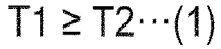
- To satisfy the expression (1), the angle θ between the large-diameter
inner surface 81a of the large-diameter ring 81 and the inclinedinner surface 81c (seeFig. 7 ) is 5° to 15°, for example. - (7) The result of subtracting the length L2 from the length L3 is 93% to 99% of the length L4 of the tapered
roller 63 in the direction extending along the axis of roller A3 (seeFig. 3 ). The length L4 is equal to the result of subtracting the radius R1 of the small-diameter-siderounded portion 63e from the entire length L5 of the taperedroller 63 in the direction extending along the axis of roller A3. - (8) The width W2 indicating the distance between adjacent two of the second fall-out preventing
portions 89 in the circumferential direction (seeFig. 5 ) is 92% to 97% of the diameter D1. - The following now describes the method of manufacturing the
retainer 64. As shown inFig. 7 , theretainer 64 is injection molded using twoseparable molds 101 and 102 (afirst mold 101 and a second mold 102). The parting line PL of the twomolds outer end surface 81e, large-diameterinner surface 81a and inclinedinner surface 81c of the large-diameter ring 81, thestep 87a andouter surface 85 of thecolumns 83, the inclinedouter surface 82d and axiallyinner end surface 82b of the small-diameter ring 82. - A direction Y1 indicates the direction in which the two
molds Fig. 7 . Since the parting line PL extends in the above-described manner, the fall-out preventingportions first mold 101. In other words, the fall-out preventingportions molds - The following now describes the method of assembling the first
main bearing 6A. To begin with, the taperedrollers 63 are combined with theretainer 64. Here, the taperedrollers 63 are combined from the side where the second fall-out preventingportion 89 is positioned, that is to say, from the inside in the radial direction. More specifically, the portion of each taperedroller 63 including the small-diameter surface 63b is inserted between the second and first fall-out preventingportions retainer 64 from the inside in the radial direction, after which the portion of each taperedroller 63 including the large-diameter surface 63a is housed in thepocket 84. - The first step of combining the portion of the tapered
roller 63 including the small-diameter surface 63b with theretainer 64 may involve pushing the portion of the taperedroller 63 including the small-diameter surface 63b into the second fall-out preventingportion 89 from the inside in the radial direction. Here, the portion of the taperedroller 63 including the small-diameter surface 63b pushes and expands the second fall-out preventingportion 89 while the taperedroller 63 is being combined. The small-diameter surface 63b of the taperedroller 63 has a smaller diameter than the large-diameter surface 63a. Additionally, the second fall-out preventingportion 89 is sufficiently smaller than the first fall-out preventingportion 88. For these reasons, no excessive pressing force is required to combine the taperedroller 63 with theretainer 64. - If the tapered
roller 63 is combined with theretainer 64 from the inside in the radial direction, the taperedsurface 63c of the taperedroller 63 touches theinclined surface 88a of the first fall-out preventingportion 88. This can result in preventing the taperedroller 63 from falling out of theretainer 64 toward the outside in the radial direction. Here, since the first fall-out preventingportion 88 satisfies the condition described in the above section (2), the taperedroller 63 can be reliably stopped by the first fall-out preventingportion 88. This can result in reliably preventing the taperedroller 63, which is combined with theretainer 64 from the inside in the radial direction, from falling out of theretainer 64 toward the outside in the radial direction. - While being housed in the
pocket 84 of theretainer 64, the taperedroller 63 remains in contact with theinclined surface 88a of the first fall-out preventingportion 88 and also with theinclined surface 89a of the second fall-out preventingportion 89. Accordingly, the second fall-out preventingportion 89 also prevents the taperedroller 63 from falling out of theretainer 64 toward the inside in the radial direction. Having the above-described configuration, theretainer 64 can keep the orientation of the taperedroller 63. In other words, theretainer 64 can retain the taperedroller 63. - After this, the
retainer 64 having the taperedrollers 63 combined is housed between the outer andinner races main bearing 6A. - Subsequently, a lubricating oil is poured inside the first
main bearing 6A. Here, the first and second fall-out preventingportions 88 are positioned closer to the small-diameter ring 82 than to the large-diameter ring 81. This leaves, on the large-diameter ring 81 side, a fully open space S (seeFig. 2 ) between the large-diameter ring 81 and the small-diameter ring 82. The space S can establish communication between the outside and the inside of the firstmain bearing 6A in the radial direction. This can improve the oil flowability, thereby allowing the lubricating oil to easily and sufficiently reach the respective parts of the firstmain bearing 6A. - The following now describes how the
speed reducer 1 works. The rotational force provided from the external motor (not shown) is transmitted to the crankshafts 4 via theinput gear 18 andspur gear 17. As the crankshafts 4 rotate, the first and second oscillating gears 5A and 5B, which support the crankshafts 4, oscillatorily rotate. This results in the carrier 3 rotating on the axis of rotation A1 at the reduced speed when compared with the rotation produced by the external motor. Via themain bearings outer tube 2. - If the
outer tube 2 is fixedly attached to an external device or the like, which is not shown, the carrier 3 serves as an output unit for outputting the rotation input into the speed reducer 1 (the rotation produced by the external motor). This means that a not-shown drive member can be driven by being attached to the carrier 3. On the other hand, if the carrier 3 is fixedly attached to an external device or the like, which is not shown, theouter tube 2 serves as an output unit for outputting the rotation input into the speed reducer 1 (the rotation produced by the external motor). This means that a not-shown drive member can be driven by being attached to theouter tube 2. As described, theouter tube 2 and carrier 3 can both serve as an output unit (first and second output units recited in the claims). - In the above-described embodiment, the
retainer 64 of themain bearings portions portion 88 can prevent the taperedroller 63 from falling out of theretainer 64 toward the outside in the radial direction. The second fall-out preventingportion 89 can prevent the taperedroller 63 from falling out of theretainer 64 toward the inside in the radial direction. Consequently, themain bearings retainer 64 has only one type of fall-out preventing portions, the taperedrollers 63 could fall out of theretainer 64 toward the outside or inside in the radial direction. This will obstruct the assembling of themain bearings - Each
column 83 has the two types of fall-out preventingportions diameter ring 82 than to the large-diameter ring 81. This leaves, on the large-diameter ring 81 side, the fully open space S (seeFig. 2 ) between the large-diameter ring 81 and the small-diameter ring 82. This can improve the flowability of the oil into the inside of themain bearings main bearings - Since the two types of fall-out preventing
portions diameter ring 82 than to the large-diameter ring 81, the space S can be left on the large-diameter ring 81 side. The large-diameter ring 81 has a longer circumferential length than the small-diameter ring 82. As left on the large-diameter ring 81 side, the space S can have a larger opening area than when left on the small-diameter ring 82 side. - Due to their structural features, the tapered
rollers 63, which are used as the rolling elements of themain bearings diameter surface 63b faces the small-diameter ring 82 of theretainer 64. In other words, the small-diameter surface 63b of the taperedrollers 63 are positioned on the small-diameter ring 82 side, where the two types of fall-out preventingportions retainer 64 in a more facilitated manner than in a case where the portion of the taperedroller 63 including the large-diameter surface 63a is placed where the fall-out preventingportions - The length L1 of the first fall-out preventing
portion 88 is different from the length L2 of the second fall-out preventingportion 89. The taperedrollers 63 can be combined with theretainer 64 more easily as the taperedrollers 63 are combined with theretainer 64 from the side where the shorter fall-out preventing portion is provided. The different lengths L1 and L2 can result in a more reliable oil flow space (space S). - In addition, the lengths L1 and L2 satisfy the relation described in the above section (1). Therefore, the tapered
rollers 63 can be combined with theretainer 64 from the inside in the radial direction in a smoother way. When the taperedrollers 63 are combined with theretainer 64 from the inside in the radial direction, the taperedrollers 63 may accidentally fall out of theretainer 64 toward the outside in the radial direction. This can be reliably prevented from happening since the length L1 of the first fall-out preventingportion 88 is greater than the length L2 of the second fall-out preventingportion 89. - The length L1 of the first fall-out preventing
portion 88 satisfies the relation described in the above section (2). Accordingly, theinclined surface 88a of the first fall-out preventingportion 88 can reliably butt up against the taperedsurface 63c of the taperedroller 63. When the taperedrollers 63 are assembled into theretainer 64 from the inside in the radial direction, the taperedrollers 63 may accidentally fall out of theretainer 64 toward the outside in the radial direction. This can be more reliably prevented from happening. Theretainer 64 can thus reliably retain the taperedroller 63. - The thickness T1 of the large-
diameter ring 81 in the radial direction and the thickness T2 indicating the distance between theouter surface 85 of thecolumn 83 and the secondflat surface 86c satisfies the relation described in the above section (6), i.e., the expression (1). - The large-
diameter ring 81 is arranged at a distance and outside the outerperipheral surface 66a of therestriction wall 66 of theinner race 62A in the radial direction. In other words, the large-diameter ring 81 needs to be configured such that it can avoid interfering with therestriction wall 66. In addition, draft should be applied to the parts of theretainer 64, which is injection molded using the twomolds diameter ring 81 in the radial direction is preferably small. This is because thefirst mold 101 could be more easily removed from theretainer 64 if the large-diameterinner surface 81a is inclined with respect to the axis of roller A3 so that it can extend along the inclinedinner surface 81c of the large-diameter ring 81. Another reason is that a small thickness T1 can help the large-diameter ring 81 avoiding the interference with therestriction wall 66. - A small thickness T1, however, would compromise the rigidity of the
retainer 64. To address this issue, the relation described in the above section (6), i.e., the expression (1) is intentionally satisfied. This can allow theretainer 64 to achieve improved rigidity. To satisfy the relation described in the above section (6), i.e., the expression (1) and, at the same time, to allow thefirst mold 101 to be removed from theretainer 64 smoothly, the angle θ formed between the large-diameterinner surface 81a of the large-diameter ring 81 and the inclinedinner surface 81c (seeFig. 7 ) is preferably 5° to 15°. - In order to make the
retainer 64 from a resin, the twomolds first mold 101 can shape the fall-out preventingportions portions molds retainer 64 uses only thefirst mold 101 to shape the fall-out preventingportions portions first mold 101. If a change is made in the shape of the fall-out preventingportions first mold 101 that needs to be changed. Accordingly, the present embodiment can reduce the manufacturing cost. - In the
retainer 64, thestep 87a of the first fall-out preventing portion 88 (the first side surface) is located on the same straight line as the inclinedinner surface 81c of the large-diameter ring 81 (second side surface). In this way, the parting line PL for themolds step 87a, the inclinedinner surface 81c and part of theouter surface 85 of the column 83 (the portion of theouter surface 85 that is positioned closer to the small-diameter ring 82 with respect to thestep 87a). Since the parting line PL is configured in the above-described manner, the fall-out preventingportions first mold 101. - The
speed reducer 1 can be assembled in an improved manner as constituted by the above-describedmain bearings speed reducer 1 can achieve an extended product lifetime. - The embodiments described herein are not intended to necessarily limit the present invention to any specific embodiments. Various modifications can be made to these embodiments without departing from the true scope and spirit of the present invention.
- For example, according to the above-described embodiment, each
column 83 has the two fall-out preventingportions diameter ring 82 than to the large-diameter ring 81. The present embodiment, however, is not limited to such. Eachcolumn 83 may have the two fall-out preventingportions diameter ring 81 than to the small-diameter ring 82. Even in this case, an open space can be left between the large- and small-diameter rings 81 and 82. - According to the above-described embodiment, the length L1 of the first fall-out preventing
portion 88 and the length L2 of the second fall-out preventingportion 89 satisfy the relation described in the above section (1). The present embodiment, however, is not limited to such, and the lengths L1 and L2 just need to be different from each other. Consequently, themain bearings - In the above-described embodiment, the
main bearings rollers 63 are used as the rolling elements. The present embodiment, however, is not limited to such, and the above-describedretainer 64 can be applicable to various types of bearings. For example, the above-describedretainer 64 can be applicable to cages for retaining as rolling elements cylindrical or spherical rollers. - According to the above-described embodiment, the parts of the
retainer 64 have dimensions determined to satisfy the relations described in the sections (1) to (8). The present embodiment, however, is not limited to such, and the parts of theretainer 64 do not need to have dimensions satisfying the relations described in the sections (1) to (8). Theretainer 64 is at least required to have the two types of fall-out preventingportions diameter ring 81 or the small-diameter ring 82 than to the other. - According to the above-described embodiment, the
columns 83 each have the outer andinner surfaces inner surface 86 is divided into the firstflat surface 86a,inclined surface 86b and secondflat surface 86c. According to the foregoing description, the parting line PL for the twomolds outer end surface 81e, large-diameterinner surface 81a, and inclinedinner surface 81c of the large-diameter ring 81, thestep 87a andouter surface 85 of eachcolumn 83, the inclinedouter surface 82d and axiallyinner end surface 82b of the small-diameter ring 82. The present embodiment, however, is not limited to such, and thecolumns 83 can be shaped in any manners. The parting line PL can be set depending on the shape of thecolumns 83. Note that, however, the parting line PL is preferably determined such that the fall-out preventingportions molds - In the above-described embodiment, the
speed reducer 1 is an eccentric oscillation speed reducer including the crankshafts 4, oscillating gears 5A and 5B, and the like. In the above-described embodiment, thespeed reducer 1 has themain bearings main bearings speed reducers 1. Themain bearings speed reducer 1. For example, themain bearings - The foregoing embodiments disclosed herein describe a plurality of physically separate constituent parts. They may be combined into a single part, and any one of them may be divided into a plurality of physically separate constituent parts. Irrespective of whether or not the constituent parts are integrated, they are acceptable as long as they are configured to solve the problems.
-
- 1
- speed reducer (transmission)
- 2
- outer tube (first output portion, second output portion)
- 3
- carrier (first output portion, second output portion)
- 6A
- first main bearing (bearing)
- 6B
- second main bearing (bearing)
- 10
- reduction unit (speed changing unit)
- 18
- input gear (input portion)
- 61A, 61B
- outer race
- 62A, 62B
- inner race
- 63
- tapered roller (rolling element)
- 64
- cage
- 81
- large-diameter ring
- 81c
- inclined inner surface (second side surface)
- 87a
- step (first side surface)
- 82
- small-diameter ring
- 83
- column
- 85
- outer surface
- 86
- inner surface
- 86a
- first flat surface
- 86b
- inclined surface
- 86c
- second flat surface
- 88
- first fall-out preventing portion
- 89
- second fall-out preventing portion
- 101
- first mold (mold)
- 102
- second mold (mold)
- L1
- length (length of first fall-out preventing portion)
- L2
- length (length of second fall-out preventing portion)
- PL
- parting line
- T1, T2
- thickness
Claims (12)
- A retainer (64) for retaining a plurality of rolling elements (63) of a bearing (6A, 6B), the retainer (64) comprising:an annular large-diameter ring (81);an annular small-diameter ring (82) having a smaller outer diameter than the large-diameter ring (81); anda plurality of columns (83) extending in a radial direction of the large- and small-diameter rings (81 and 82) to connect the large- and small-diameter rings (81 and 82),wherein the columns (83) are arranged at equal intervals in a circumferential direction and between the rolling elements (63), andwherein the columns (83) each have:a first fall-out preventing portion (88) for preventing the rolling elements (63) from falling out of the large- and small-diameter rings (81 and 82) toward a first direction; anda second fall-out preventing portion (89) for preventing the rolling elements (63) from falling out of the large- and small-diameter rings (81 and 82) toward a second direction opposite to the first direction, andwherein the first and second fall-out preventing portions (88 and 89) are positioned closer to one of the large-diameter ring (81) or the small-diameter ring (82) than to another of the large-diameter ring (81) or the small-diameter ring (82).
- The retainer (64) of claim 1, wherein the first and second fall-out preventing portions (88 and 89) are positioned closer to the small-diameter ring (82) than to the large-diameter ring (81).
- The retainer (64) of claim 2, wherein the rolling elements (63) include tapered rollers.
- The retainer (64) of claim 3, wherein a length (L1) of the first fall-out preventing portion (88) in a direction orthogonal to the first and second directions is different from a length (L2) of the second fall-out preventing portion (89) in a direction orthogonal to the first and second directions.
- The retainer (64) of claim 4,wherein the first fall-out preventing portion (88) is positioned outside in the radial direction,wherein the second fall-out preventing portion (89) is positioned inside in the radial direction,wherein the length (L2) of the second fall-out preventing portion (89) is measured in a direction in which an axis (A3) of the tapered rollers (63) extends,wherein the length (L1) of the first fall-out preventing portion (88) is measured in the direction in which the axis (A3) of the tapered rollers (63) extends, andwherein the length (L2) of the second fall-out preventing portion (89) is less than the length (L1) of the first fall-out preventing portion (88).
- The retainer (64) of claim 5, wherein the length (L1) of the first fall-out preventing portion (88) is equal to or greater than 50% of a length (L3) indicating a distance between the large- and small-diameter rings (81 and 82).
- The retainer (64) of claim 5 or 6,
wherein the columns (83) each have:an outer surface (85) located outside in the radial direction; andan inner surface (86) located inside in the radial direction,wherein the outer surface (85) is a flat surface extending from the small-diameter ring (82) to the large-diameter ring (81),wherein the inner surface (86) has:a first flat surface (86a) extending from the small-diameter ring (82) toward the large-diameter ring (81) in a direction in which the outer surface (85) extends;an inclined surface (86b) extending obliquely from an end of the first flat surface (86a) facing the large-diameter ring (81) toward the outer surface (85); anda second flat surface (86c) extending from an end of the inclined surface (86b) facing the large-diameter ring (81) to the large-diameter ring (81) in the direction in which the outer surface (85) extends, andwherein a relation of T1 ≥ T2 is satisfied, where T1 represents a thickness in the radial direction of an end of the large-diameter ring (81) that faces away from the small-diameter ring (82) and T2 represents a thickness indicating a distance between the outer surface (85) and the second flat surface (86c). - The retainer (64) of claim 7,wherein the large-diameter ring (81), the small-diameter ring (82) and the columns (83) are made from a resin and shaped by two separable molds (101 and 102), andwherein the first and second fall-out preventing portions (88 and 89) are both located on one of sides defined with respect to a parting line (PL) for the two separable molds (101 and 102).
- The retainer (64) of claim 8,wherein a first side surface (87a) of the first fall-out preventing portion (88) that faces the large-diameter ring (81) is located on a same straight line as a second side surface (81c) of the large-diameter ring (81) that faces inside in the radial direction, andwherein the first side surface (87a), the second side surface (81c) and a portion of the outer surface (85) of the each column (83) that is positioned on the small-diameter ring (82) side with respect to the first side surface (87a) are arranged along the parting line (PL).
- A bearing (6A, 6B) comprising:an outer race (61A, 61B);an inner race (62A, 62B) located inside the outer race (61A, 61B) in a radial direction;a plurality of rolling elements (63) rollably housed between the inner race (62A, 62B) and the outer race (61A, 61B); anda retainer (64) retaining the plurality of rolling elements (63),wherein the retainer (64) includes:an annular large-diameter ring (81);an annular small-diameter ring (82) having a smaller outer diameter than the large-diameter ring (81); anda plurality of columns (83) connecting the large- and small-diameter rings (81 and 82), the columns (83) being arranged at equal intervals in a circumferential direction and between the rolling elements (63), andwherein the columns (83) each have:a first fall-out preventing portion (88) for preventing the rolling elements (63) from falling out of the large- and small-diameter rings (81 and 82) toward a first direction; anda second fall-out preventing portion (89) for preventing the rolling elements (63) from falling out of the large- and small-diameter rings (81 and 82) toward a second direction opposite to the first direction, andwherein the first and second fall-out preventing portions (88 and 89) are positioned closer to one of the large-diameter ring (81) or the small-diameter ring (82) than to another of the large-diameter ring (81) or the small-diameter ring (82).
- A transmission (1) comprising:an input part (18) for receiving an input rotational force;a speed changing unit (10) for changing a speed of rotation of the input part (18);a first output part and a second output part (2 and 3) to which the rotation of the input part (18) is transmitted via the speed changing unit (10), the first and second output parts (2 and 3) being configured to rotate relative to each other; anda bearing (6A, 6B) supporting the first and second output parts (2 and 3) such that the first and second output parts (2 and 3) are rotatable relative to each other,wherein the bearing (6A, 6B) includes:an outer race (61A, 61B);an inner race (62A, 62B) located inside the outer race (61A, 61B) in a radial direction;a plurality of rolling elements (63) rollably housed between the inner race (62A, 62B) and the outer race (61A, 61B); anda retainer (64) retaining the plurality of rolling elements (63),wherein the retainer (64) includes:an annular large-diameter ring (81);an annular small-diameter ring (82) having a smaller outer diameter than the large-diameter ring (81); anda plurality of columns (83) connecting the large- and small-diameter rings (81 and 82), the columns (83) being arranged at equal intervals in a circumferential direction and between the rolling elements (63),wherein the columns (83) each have:a first fall-out preventing portion (88) for preventing the rolling elements (63) from falling out of the large- and small-diameter rings (81 and 82) toward a first direction; anda second fall-out preventing portion (89) for preventing the rolling elements (63) from falling out of the large- and small-diameter rings (81 and 82) toward a second direction opposite to the first direction, andwherein the first and second fall-out preventing portions (88 and 89) are positioned closer to one of the large-diameter ring (81) or the small-diameter ring (82) than to another of the large-diameter ring (81) or the small-diameter ring (82).
- A method of manufacturing a retainer (64) for retaining a plurality of rolling elements (63) of a bearing (6A, 6B), the retainer (64) having a first fall-out preventing portion (88) for preventing the rolling elements (63) from falling out of the retainer (64) toward a first direction and a second fall-out preventing portion (89) for preventing the rolling elements (63) from falling out of the retainer (64) toward a second direction opposite to the first direction, the first fall-out preventing portion being positioned on one of sides defined relative to the rolling elements and the second fall-out preventing portion being positioned on said one of sides defined relative to the rolling elements, the method comprising steps of:making the retainer (64) from a resin by means of injection molding using two molds (101 and 102); andseparating the two molds (101 and 102) from each other at a parting line (PL),wherein one of the two molds (101 and 102) is used to make the first and second fall-out preventing portions (88 and 89).
Applications Claiming Priority (1)
| Application Number | Priority Date | Filing Date | Title |
|---|---|---|---|
| JP2023068927A JP2024154824A (en) | 2023-04-20 | 2023-04-20 | Cage, bearing, transmission, and method for manufacturing the cage |
Publications (1)
| Publication Number | Publication Date |
|---|---|
| EP4455501A1 true EP4455501A1 (en) | 2024-10-30 |
Family
ID=90366160
Family Applications (1)
| Application Number | Title | Priority Date | Filing Date |
|---|---|---|---|
| EP24164154.7A Pending EP4455501A1 (en) | 2023-04-20 | 2024-03-18 | Retainer, bearing, transmission and method of manufacturing retainer |
Country Status (5)
| Country | Link |
|---|---|
| EP (1) | EP4455501A1 (en) |
| JP (1) | JP2024154824A (en) |
| KR (1) | KR20240155763A (en) |
| CN (1) | CN118815831A (en) |
| TW (1) | TWI906790B (en) |
Citations (5)
| Publication number | Priority date | Publication date | Assignee | Title |
|---|---|---|---|---|
| JP2014202284A (en) | 2013-04-04 | 2014-10-27 | 日本精工株式会社 | Resin cage for tapered roller bearing |
| WO2015129709A1 (en) * | 2014-02-25 | 2015-09-03 | Ntn株式会社 | Tapered roller bearing |
| US20160040716A1 (en) * | 2013-04-04 | 2016-02-11 | Nsk Ltd. | Resin cage for tapered roller bearing and tapered roller bearing including the resin cage |
| WO2019065768A1 (en) * | 2017-09-28 | 2019-04-04 | Ntn株式会社 | Retainer for tapered roller bearing, and tapered roller bearing |
| WO2021246209A1 (en) * | 2020-06-03 | 2021-12-09 | Ntn株式会社 | Tapered roller bearing |
Family Cites Families (1)
| Publication number | Priority date | Publication date | Assignee | Title |
|---|---|---|---|---|
| CN205078616U (en) * | 2015-09-24 | 2016-03-09 | 日本精工株式会社 | Thrust cylindrical roller is holder and thrust cylindrical roller bearing for bearing |
-
2023
- 2023-04-20 JP JP2023068927A patent/JP2024154824A/en active Pending
-
2024
- 2024-03-05 CN CN202410245852.0A patent/CN118815831A/en active Pending
- 2024-03-11 TW TW113108787A patent/TWI906790B/en active
- 2024-03-13 KR KR1020240035135A patent/KR20240155763A/en active Pending
- 2024-03-18 EP EP24164154.7A patent/EP4455501A1/en active Pending
Patent Citations (5)
| Publication number | Priority date | Publication date | Assignee | Title |
|---|---|---|---|---|
| JP2014202284A (en) | 2013-04-04 | 2014-10-27 | 日本精工株式会社 | Resin cage for tapered roller bearing |
| US20160040716A1 (en) * | 2013-04-04 | 2016-02-11 | Nsk Ltd. | Resin cage for tapered roller bearing and tapered roller bearing including the resin cage |
| WO2015129709A1 (en) * | 2014-02-25 | 2015-09-03 | Ntn株式会社 | Tapered roller bearing |
| WO2019065768A1 (en) * | 2017-09-28 | 2019-04-04 | Ntn株式会社 | Retainer for tapered roller bearing, and tapered roller bearing |
| WO2021246209A1 (en) * | 2020-06-03 | 2021-12-09 | Ntn株式会社 | Tapered roller bearing |
Also Published As
| Publication number | Publication date |
|---|---|
| JP2024154824A (en) | 2024-10-31 |
| CN118815831A (en) | 2024-10-22 |
| TWI906790B (en) | 2025-12-01 |
| TW202447101A (en) | 2024-12-01 |
| KR20240155763A (en) | 2024-10-29 |
Similar Documents
| Publication | Publication Date | Title |
|---|---|---|
| US8545357B2 (en) | Gear transmission | |
| EP2077404A1 (en) | Reduction gear | |
| JP2010156430A (en) | Deceleration device | |
| JP5283591B2 (en) | Series of simple planetary gear reducers | |
| JP6932068B2 (en) | Eccentric swing type gear device | |
| CN103547823A (en) | Rolling bearing comprising a housing having two parts and method of manufacturing such a bearing | |
| EP2055972A2 (en) | Arrangement with two lubricated rolling element bearings for supporting a pinion shaft | |
| JP2009204004A (en) | Bearing device for turbocharger | |
| KR20170015193A (en) | Eccentric oscillation-type gear device and controlling method thereof | |
| CN112145557B (en) | Bearings and reducers | |
| EP2730805B1 (en) | Reduction gear | |
| WO2020189439A1 (en) | Inner-ring-separable angular ball bearing | |
| CN206478172U (en) | A kind of Eccentrically swinging gear device | |
| US20210172476A1 (en) | Radial roller bearing cage | |
| JP2018194014A (en) | Method of manufacturing cylindrical roller bearing and holder | |
| US6068409A (en) | Synthetic resin cage for roller bearing | |
| JP2024154824A (en) | Cage, bearing, transmission, and method for manufacturing the cage | |
| US20050064977A1 (en) | Roller/retainer assembly for planetary gear and planetary gears support using the same | |
| US20070117675A1 (en) | Washer and planetary gear set having the same | |
| CN111075890B (en) | Eccentric swing type speed reducer | |
| JP7800287B2 (en) | Transmission | |
| US10955007B2 (en) | Bearing retaining mechanism | |
| JP7624847B2 (en) | Transmission device | |
| JPH08200375A (en) | Roller bearing cage | |
| JP2017062000A (en) | Reduction gear |
Legal Events
| Date | Code | Title | Description |
|---|---|---|---|
| PUAI | Public reference made under article 153(3) epc to a published international application that has entered the european phase |
Free format text: ORIGINAL CODE: 0009012 |
|
| STAA | Information on the status of an ep patent application or granted ep patent |
Free format text: STATUS: REQUEST FOR EXAMINATION WAS MADE |
|
| 17P | Request for examination filed |
Effective date: 20240318 |
|
| AK | Designated contracting states |
Kind code of ref document: A1 Designated state(s): AL AT BE BG CH CY CZ DE DK EE ES FI FR GB GR HR HU IE IS IT LI LT LU LV MC ME MK MT NL NO PL PT RO RS SE SI SK SM TR |