EP4455498A1 - Rotating shaft assembly and terminal device - Google Patents
Rotating shaft assembly and terminal device Download PDFInfo
- Publication number
- EP4455498A1 EP4455498A1 EP23870073.6A EP23870073A EP4455498A1 EP 4455498 A1 EP4455498 A1 EP 4455498A1 EP 23870073 A EP23870073 A EP 23870073A EP 4455498 A1 EP4455498 A1 EP 4455498A1
- Authority
- EP
- European Patent Office
- Prior art keywords
- shaft assembly
- rotating shaft
- rotating
- disposed
- swing arm
- Prior art date
- Legal status (The legal status is an assumption and is not a legal conclusion. Google has not performed a legal analysis and makes no representation as to the accuracy of the status listed.)
- Granted
Links
Images








Classifications
-
- G—PHYSICS
- G09—EDUCATION; CRYPTOGRAPHY; DISPLAY; ADVERTISING; SEALS
- G09F—DISPLAYING; ADVERTISING; SIGNS; LABELS OR NAME-PLATES; SEALS
- G09F9/00—Indicating arrangements for variable information in which the information is built-up on a support by selection or combination of individual elements
- G09F9/30—Indicating arrangements for variable information in which the information is built-up on a support by selection or combination of individual elements in which the desired character or characters are formed by combining individual elements
-
- G—PHYSICS
- G06—COMPUTING OR CALCULATING; COUNTING
- G06F—ELECTRIC DIGITAL DATA PROCESSING
- G06F1/00—Details not covered by groups G06F3/00 - G06F13/00 and G06F21/00
- G06F1/16—Constructional details or arrangements
- G06F1/1613—Constructional details or arrangements for portable computers
- G06F1/1633—Constructional details or arrangements of portable computers not specific to the type of enclosures covered by groups G06F1/1615 - G06F1/1626
- G06F1/1675—Miscellaneous details related to the relative movement between the different enclosures or enclosure parts
- G06F1/1681—Details related solely to hinges
-
- F—MECHANICAL ENGINEERING; LIGHTING; HEATING; WEAPONS; BLASTING
- F16—ENGINEERING ELEMENTS AND UNITS; GENERAL MEASURES FOR PRODUCING AND MAINTAINING EFFECTIVE FUNCTIONING OF MACHINES OR INSTALLATIONS; THERMAL INSULATION IN GENERAL
- F16C—SHAFTS; FLEXIBLE SHAFTS; ELEMENTS OR CRANKSHAFT MECHANISMS; ROTARY BODIES OTHER THAN GEARING ELEMENTS; BEARINGS
- F16C11/00—Pivots; Pivotal connections
- F16C11/04—Pivotal connections
-
- G—PHYSICS
- G06—COMPUTING OR CALCULATING; COUNTING
- G06F—ELECTRIC DIGITAL DATA PROCESSING
- G06F1/00—Details not covered by groups G06F3/00 - G06F13/00 and G06F21/00
- G06F1/16—Constructional details or arrangements
- G06F1/1613—Constructional details or arrangements for portable computers
- G06F1/1633—Constructional details or arrangements of portable computers not specific to the type of enclosures covered by groups G06F1/1615 - G06F1/1626
- G06F1/1637—Details related to the display arrangement, including those related to the mounting of the display in the housing
- G06F1/1652—Details related to the display arrangement, including those related to the mounting of the display in the housing the display being flexible, e.g. mimicking a sheet of paper, or rollable
-
- H—ELECTRICITY
- H04—ELECTRIC COMMUNICATION TECHNIQUE
- H04M—TELEPHONIC COMMUNICATION
- H04M1/00—Substation equipment, e.g. for use by subscribers
- H04M1/02—Constructional features of telephone sets
- H04M1/0202—Portable telephone sets, e.g. cordless phones, mobile phones or bar type handsets
- H04M1/0206—Portable telephones comprising a plurality of mechanically joined movable body parts, e.g. hinged housings
- H04M1/0208—Portable telephones comprising a plurality of mechanically joined movable body parts, e.g. hinged housings characterized by the relative motions of the body parts
- H04M1/0214—Foldable telephones, i.e. with body parts pivoting to an open position around an axis parallel to the plane they define in closed position
- H04M1/0216—Foldable in one direction, i.e. using a one degree of freedom hinge
-
- H—ELECTRICITY
- H04—ELECTRIC COMMUNICATION TECHNIQUE
- H04M—TELEPHONIC COMMUNICATION
- H04M1/00—Substation equipment, e.g. for use by subscribers
- H04M1/02—Constructional features of telephone sets
- H04M1/0202—Portable telephone sets, e.g. cordless phones, mobile phones or bar type handsets
- H04M1/0206—Portable telephones comprising a plurality of mechanically joined movable body parts, e.g. hinged housings
- H04M1/0208—Portable telephones comprising a plurality of mechanically joined movable body parts, e.g. hinged housings characterized by the relative motions of the body parts
- H04M1/0214—Foldable telephones, i.e. with body parts pivoting to an open position around an axis parallel to the plane they define in closed position
- H04M1/0216—Foldable in one direction, i.e. using a one degree of freedom hinge
- H04M1/022—The hinge comprising two parallel pivoting axes
-
- H—ELECTRICITY
- H04—ELECTRIC COMMUNICATION TECHNIQUE
- H04M—TELEPHONIC COMMUNICATION
- H04M1/00—Substation equipment, e.g. for use by subscribers
- H04M1/02—Constructional features of telephone sets
- H04M1/0202—Portable telephone sets, e.g. cordless phones, mobile phones or bar type handsets
- H04M1/0206—Portable telephones comprising a plurality of mechanically joined movable body parts, e.g. hinged housings
- H04M1/0208—Portable telephones comprising a plurality of mechanically joined movable body parts, e.g. hinged housings characterized by the relative motions of the body parts
- H04M1/0235—Slidable or telescopic telephones, i.e. with a relative translation movement of the body parts; Telephones using a combination of translation and other relative motions of the body parts
- H04M1/0237—Sliding mechanism with one degree of freedom
-
- H—ELECTRICITY
- H04—ELECTRIC COMMUNICATION TECHNIQUE
- H04M—TELEPHONIC COMMUNICATION
- H04M1/00—Substation equipment, e.g. for use by subscribers
- H04M1/02—Constructional features of telephone sets
- H04M1/0202—Portable telephone sets, e.g. cordless phones, mobile phones or bar type handsets
- H04M1/026—Details of the structure or mounting of specific components
- H04M1/0266—Details of the structure or mounting of specific components for a display module assembly
- H04M1/0268—Details of the structure or mounting of specific components for a display module assembly including a flexible display panel
Definitions
- This application relates to the field of rotating shaft technologies, and in particular, to a rotating shaft assembly and a terminal device.
- a rotating shaft assembly is an important component in a terminal device with a foldable screen effect, such as a mobile phone or a tablet computer.
- a rotating shaft assembly includes a base and a swing arm that is rotatably connected to the base.
- a thickness of the base and a thickness of the swing arm are relatively large, and consequently, an overall thickness and an overall volume of the rotating shaft assembly are relatively large, and relatively large space is occupied when the rotating shaft assembly is used in the terminal device.
- Embodiments of this application are to provide a rotating shaft assembly and a terminal device, to reduce a thickness and a volume of the rotating shaft assembly and reduce a space occupancy rate of the rotating shaft assembly in the terminal device.
- An embodiment of a first aspect of this application provides a rotating shaft assembly, and the rotating shaft assembly includes:
- the at least two swing arms include a first swing arm and a second swing arm, and a swinging part of the first swing arm and a swinging part of the second swing arm are disposed on two sides of the base.
- the rotating shaft assembly further includes a shaft cover, and the shaft cover is connected to the base.
- the rotating part includes two first surfaces, and the at least one second surface is located between the two first surfaces along the rotation axis of the swinging part.
- the first portion includes a first body part and two connecting parts located on two sides of the first body part, each connecting part includes two pressing blocks, each first surface is disposed opposite to a third surface of one pressing block, and the third surface is a side surface that is of the pressing block and that faces the second portion.
- each connecting part further includes a connecting member, and the connecting member is connected to the two pressing blocks.
- the connecting member is in a strip shape
- a first strip groove is disposed on a side surface that is of the rotating part and that is away from the shaft cover, the first strip groove extends in a length direction of the connecting member, and at least a partial structure of the connecting member is disposed in the first strip groove.
- a first concave part is disposed on a side surface that is of the rotating part and that is away from the rotation axis of the swinging part, at least a partial structure of the pressing block is disposed in the first concave part, and a bottom wall of the first concave part includes the first surface.
- a second concave part is disposed on a side surface that is of the rotating part and that faces the rotation axis of the swinging part, a first convex part is disposed on the second portion, at least a partial structure of the first convex part extends into the second concave part, and a bottom wall of the second concave part includes the second surface.
- a first limiting block is disposed on the bottom wall of the second concave part, and the first limiting block is located on a side that is of the rotating part and that is away from the swinging part; and a third concave part is disposed on a side surface that is of the first convex part and that faces the second concave part, and at least a partial structure of the first limiting block is disposed in the third concave part.
- a first through hole is disposed on the swinging part, and when at least two swing arms are in an unfolded state, an end part of the second portion extends into the first through hole in a thickness direction of the rotating shaft assembly.
- a swinging part of the first swing arm and a swinging part of the second swing arm are symmetrically disposed on two sides of the base.
- both the at least one first surface and the at least one second surface are arc-shaped surfaces.
- both the at least one first surface and the at least one second surface are circular arc surfaces, and a central axis of the at least one first surface coincides with a central axis of the at least one second surface.
- a thickness of the rotating part varies in a radial direction.
- At least a partial structure of the rotating part is disposed in the first sliding groove.
- the first portion and the second portion are an integral structure.
- a manner of connecting the first portion and the second portion includes at least one of a welding connection, a bonding connection, a screw connection, and a nut connection.
- An embodiment of a second aspect of this application provides a terminal device.
- the terminal device includes a housing, a flexible display screen, and the rotating shaft assembly according to any item above, where the flexible display screen is connected to the housing, the flexible display screen includes a bending region, the rotating shaft assembly is located on a non-display side of the flexible display screen, and the rotating shaft assembly is disposed in a correspondence with the bending region.
- the terminal device is a terminal device with a foldable screen.
- the first sliding groove is formed between the first portion and the second portion of the base, and the rotating part of the swing arm is slidably connected to the base by using the first sliding groove.
- the swinging part is disposed outside the first sliding groove, and the swinging part rotates relative to the base in a process in which the rotating part slides relative to the first sliding groove.
- the rotating shaft assembly is subjected to external force, and when the rotating part is in contact with the first portion or the second portion, a force-bearing surface of the rotating part relative to the first portion and a force-bearing surface of the rotating part relative to the second portion are located at different positions, and therefore, force borne by the rotating part, force borne by the first portion, and force borne by the second portion are relatively scattered, so that force borne by the rotating part on the first surface and the second surface is relatively small, and force borne by a side surface that is of the first portion and that is opposite to the first surface and force borne by a side surface that is of the second portion and that is opposite to the second surface are relatively small.
- rigidity of the rotating shaft assembly does not need to be increased by increasing a thickness of the swing arm, a thickness of the first portion, and a thickness of the second portion, so that a thickness and a volume of the rotating shaft assembly can be reduced, and a space occupancy rate of the rotating shaft assembly in the terminal device can be reduced.
- any product or method for implementing this application does not necessarily need to simultaneously achieve all the foregoing advantages.
- first, second, and third are used in this specification to describe various elements, components, regions, layers, and/or segments, the elements, components, regions, layers, and/or segments are not limited by these terms. These terms are merely used to distinguish one element, component, region, layer, or segment from another element, component, region, layer, or segment. Terms such as “first” and “second” and other numeric terms are not intended to imply a sequence or an order when being used in this specification unless expressly stated by the context. Therefore, a first element, component, region, layer, or segment discussed below may be referred to as a second element, component, region, layer, or segment without departing from the teachings of the example implementations.
- a spatial relational term may be used in this specification to describe a relationship between one element or feature shown in the figure and another element or feature.
- These relational terms are, for example, “interior”, “exterior”, “inner side”, “outer side”, “under”, “below”, “on, and “above”. It should be understood that such spatial relational terms are intended to include different orientations of a used or operated apparatus in addition to orientations depicted in the figures. For example, if the apparatus in the figure is reversed, an element described as “under another element or feature” or “below another element or feature” is then directed to “on another element or feature” or “above another element or feature". Therefore, an example term “below "may be included in orientations "on” and "under”.
- the apparatus may be otherwise directed, for example, is rotated by 90 degrees or in another direction, and a spatial relative relationship descriptor used herein is correspondingly explained.
- embodiments of this application provide a rotating shaft assembly and a terminal device.
- the rotating shaft assembly and the terminal device that are provided in the embodiments of this application are described in detail below with reference to the accompanying drawings.
- the rotating shaft assembly may be used in a terminal device with a foldable screen effect, such as a mobile phone, a tablet computer, a notebook computer, and a watch, and the rotating shaft assembly may be further used in another device that uses a rotating shaft or a hinge. This is not limited in this application.
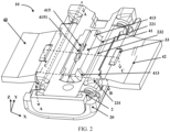
- an embodiment of a first aspect of this application provides a rotating shaft assembly 10.
- the rotating shaft assembly 10 includes a base 1 and a swing arm 4, the base 1 includes a first portion 2 and a second portion 3 that are fixedly connected, and a first sliding groove 21 is formed between the first portion 2 and the second portion 3.
- the swing arm 4 includes a rotating part 41 and a swinging part 42.
- the rotating part 41 is slidably connected to the first sliding groove 21. When the rotating part 41 slides relative to the first sliding groove 21, the swinging part 42 rotates relative to the first portion 2.
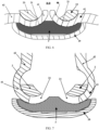
- the rotating part 41 includes at least one first surface 411 and at least one second surface 412, the at least one first surface 411 is disposed opposite to a side surface of the first portion 2, the at least one second surface 412 is disposed opposite to a side surface of the second portion 3, and as shown in FIG. 5 , along a rotation axis L of the swinging part 42, at least a portion of the first surface 411 and at least a portion of the second surface 412 are staggered.
- a width direction of the rotating shaft assembly 10 is defined as an X direction
- a length direction of the rotating shaft assembly 10 is defined as a Y direction
- a thickness direction of the rotating shaft assembly 10 is defined as a Z direction.
- An extension direction of the rotation axis L of the swinging part 42 in the rotating shaft assembly 10 is parallel to the length direction Y of the rotating shaft assembly 10, and the extension direction of the rotation axis L of the swinging part 42 in the rotating shaft assembly 10 is perpendicular to the width direction Y and the thickness direction Z of the rotating shaft assembly 10.
- the width direction X of the rotating shaft assembly 10 is a width direction X' of the terminal device
- the length direction Y of the rotating shaft assembly 10 is a length direction Y' of the terminal device
- the thickness direction Z of the rotating shaft assembly 10 is a thickness direction Z' of the terminal device.
- each first surface 411 and each second surface 412 are staggered along the rotation axis L of the swinging part 42; in other words, the orthographic projection of the at least one first surface 411 does not overlap the orthographic projection of the at least one second surface 412 in the thickness direction Z of the rotating shaft assembly 10.
- a partial structure of each first surface 411 and a partial structure of each second surface 412 are staggered along the rotation axis L of the swinging part 42; in other words, the orthographic projection of the at least one first surface 411 overlaps the orthographic projection of the at least one second surface 412 in the thickness direction Z of the rotating shaft assembly 10.
- an orthographic projection of an edge of the first surface 411 in the thickness direction Z overlaps an orthographic projection of an edge of a second surface 412 adjacent to the first surface 411 in the thickness direction Z.
- both the at least one first surface 411 and the at least one second surface 412 are arc-shaped surfaces.
- the first portion 2 includes a fourth surface 24.
- the fourth surface 24 is disposed opposite to the first surface 411; in other words, in the thickness direction Z, an orthographic projection of the fourth surface 24 covers the orthographic projection of the first surface 411.
- the second portion 3 includes a fifth surface 34.
- the fifth surface 34 is disposed opposite to the second surface 412; in other words, in the thickness direction Z, an orthographic projection of the fifth surface 34 covers the orthographic projection of the second surface 412.
- the first sliding groove 21 is jointly formed by a first sidewall (an upper sidewall) and a second sidewall (a lower sidewall) in the thickness direction Z and two bottom walls in the length direction Y.
- the fourth surface 24 may be used as the first sidewall of the first sliding groove 21, and the fifth surface 34 may be used as the second sidewall of the first sliding groove 21.
- the two bottom walls of the first sliding groove 21 are respectively disposed opposite to the two sidewalls of the rotating part 41 in the length direction Y.
- the first surface 411 is a region that is on the rotating part 41 and that is in contact with the first portion 2 and exerts upward pressure on the first portion 2 when the swing arm 4 is subjected to external force.
- the second surface 412 is a region that is on the rotating part 41 and that is in contact with the second portion 3 and exerts downward pressure on the second portion 3 when the swing arm 4 is subjected to external force.
- the second surface 412 of the rotating part 41 in the swing arm 4 is in contact with the fifth surface 34 of the second portion 3, and downward pressure is exerted on the second portion 3 on the second surface 412.
- the rotating part 41 includes two first surfaces 411 and a sixth surface 410 that connects the two first surfaces 411.
- the swing arm 4 in FIG. 21 is mounted on the base 1, because the two first surfaces 411 are disposed opposite to the fourth surface 24 of the first portion 2, and the sixth surface 410 is not disposed opposite to the fourth surface 24 of the first portion 2, the sixth surface 410 does not meet a definition of the first surface 411 in this application, and the sixth surface 410 does not belong to the first surface 411.
- the rotating shaft assembly 10 is subjected to external force, and when the rotating part 41 is in contact with the first portion 2 or the second portion 3, a force-bearing surface of the rotating part 41 relative to the first portion 2 and a force-bearing surface of the rotating part 41 relative to the second portion 3 are located at different positions, and therefore, force borne by the rotating part 41, force borne by the first portion 2, and force borne by the second portion 3 are relatively scattered, so that force borne by the rotating part 41 on the first surface 411 and the second surface 412 is relatively small, and force borne by a side surface that is of the first portion 2 and that is opposite to the first surface 411 and force borne by a side
- first surface 411 because the second portion 3 is not subjected to force in this region, rigidity required for the second portion 3 on the first surface 411 is relatively small, and a thickness of the second portion 3 may be correspondingly reduced; and on the second surface 412, because the first portion 2 is not subjected to force in this region, required rigidity on the second surface 412 is relatively small, and a thickness of the first portion 2 may also be correspondingly reduced.
- rigidity of the rotating shaft assembly 10 does not need to be increased by increasing a thickness of the swing arm 4, the thickness of the first portion 2, and the thickness of the second portion 3, so that a thickness and a volume of the rotating shaft assembly 10 can be reduced, and a space occupancy rate of the rotating shaft assembly 10 in the terminal device can be reduced.
- the rotating shaft assembly 10 has a relatively small thickness and volume, when the rotating shaft assembly 10 is used in a terminal device such as a mobile phone with a foldable screen, space occupied by the rotating shaft assembly 10 is relatively small, and this facilitates miniaturization and lightening of the terminal device.
- a quantity and an area of the first surface 411 may be set based on an actual requirement, and a quantity and an area of the second surface 412 may also be set based on an actual requirement. This is not limited in this application.
- the rotating shaft assembly 10 further includes a shaft cover 20, and the shaft cover 20 is connected to the base 1.
- the shaft cover 20 has accommodating space, and partial structures of the first portion 2 and the second portion 3 are disposed in the shaft cover 20.
- the shaft cover 20 may be used as a partial structure of a housing 30 of the terminal device, or the shaft cover 20 is configured to be connected to the housing 30 of the terminal device.
- the shaft cover 20 may be connected only to the first portion 2 or the second portion 3 of the base 1, or the shaft cover 20 may be connected to both the first portion 2 and the second portion 3.
- the base 1 and the shaft cover 20 may be connected by being locked by a fastener, and the fastener includes but is not limited to a screw, a bolt, a nut, and the like.
- the base 1 and the shaft cover 20 may be connected through welding or bonding.
- the at least two swing arms 4 include a first swing arm and a second swing arm, and a swinging part of the first swing arm and a swinging part of the second swing arm are disposed on two sides of the base 1.
- a structure of the first swing arm is the same as a structure of the second swing arm
- the structure of the first swing arm and the structure of the second swing arm are the same as a structure of the swing arm 4
- the swinging part of the first swing arm and the swinging part of the second swing arm are respectively disposed on two sides of the base 1 in the width direction X.
- a quantity of first swing arms may be equal to a quantity of second swing arms, or the quantity of first swing arms may not be equal to the quantity of second swing arms. This is not limited in this application.
- the swinging part of the first swing arm and the swinging part of the second swing arm are disposed on the two sides of the base 1, so that when the rotating shaft assembly 10 is used in the terminal device, the first swing arm and the second swing arm may drive middle frames, in a terminal apparatus, on two sides of the rotating shaft assembly 10 to rotate synchronously.
- the swinging part of the first swing arm and the swinging part of the second swing arm are symmetrically disposed on the two sides of the base 1.
- the quantity of first swing arms and the quantity of second swing arms may be equal, and each first swing arm is disposed in a correspondence with one second swing arm.
- Swinging parts of a first swing arm and a second swing arm that are disposed in a correspondence are symmetrically disposed on the two sides of the base 1 in the width direction X, so that when the rotating shaft assembly 10 is subjected to external force, a force-bearing situation of the swinging part of the first swing arm is similar to a force-bearing situation of the swinging part 42 of the second swing arm, and the swinging part of the first swing arm and the swinging part of the second swing arm rotate synchronously.
- the rotating shaft assembly 10 provided in this embodiment of this application is described below by using an example in which the rotating shaft assembly 10 includes two swing arms 4, that is, the rotating shaft assembly 10 includes one first swing arm and one second swing arm, and swinging parts 42 of the two swing arms 4 are respectively disposed on the two sides of the base 1.
- At least a partial structure of the rotating part 41 is disposed in the first sliding groove 21, to be slidably connected to the first sliding groove 21.
- the rotating part 41 and the swinging part 42 are an integral structure. As shown in FIG. 2 and FIG. 10 , when rotating parts 41 of the two swing arms 4 are disposed in the first sliding groove 21, the two swinging parts 42 are located on two sides that are of the two rotating parts 41 and that are away from each other. In a process in which the rotating part 41 slides relative to the first portion 2 and the second portion 3, the swinging part 42 rotates relative to the first portion 2 and the second portion 3.
- the rotating shaft assembly 10 includes an unfolded state and a closed state. As shown in FIG. 2 , FIG. 3 , FIG. 6 , and
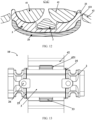
- FIG. 7 is a cross-sectional view of the rotating shaft assembly 10 in the unfolded state in a direction B-B in FIG. 2
- FIG. 7 is a cross-sectional view of the rotating shaft assembly 10 in the closed state in B-B in FIG. 2 .
- the two swinging parts 42 are away from each other and are approximately placed horizontally.
- the two swinging parts 42 are close to each other and are approximately placed vertically.
- both the two rotating parts 41 slide relative to the first portion 2 and the second portion 3, sides that are of the two rotating parts 41 and that are away from the swinging parts 42 move in directions away from each other, and sides that are of the two swinging parts 42 and that are away from the rotating parts 41 rotate in directions approaching each other.
- both the two rotating parts 41 slide relative to the first portion 2 and the second portion 3, sides that are of the two rotating parts 41 and that are away from the swinging parts 42 move in directions approaching each other, and sides that are of the two swinging parts 42 and that are away from the rotating part 41 rotate in directions away from each other.
- a rotation range of each swinging part 42 from the unfolded state to the closed state may be 85 degrees to 95 degrees. In an example, the rotation range of each swinging part 42 from the unfolded state to the closed state may be 90 degrees.
- the rotating part 41 has two first surfaces 411, and along the vertical rotation axis L that is perpendicular to the swinging part 42, an orthographic projection of at least one second surface 412 is located between orthographic projections of the two first surfaces 411.
- each rotating part 41 has two first surfaces 411 with the first portion 2.
- the rotating part 41 exerts upward pressure on the first portion 2 separately by using the two first surfaces 411, so that pressure exerted by the rotating part 41 on the first portion 2 can be further distributed, thereby further helping reduce a thickness of the swing arm 4 and a thickness of the first portion 2.
- the orthographic projections of the two first surfaces 411 are located on two sides of the orthographic projection of the at least one second surface 412, so that force-bearing surfaces of the rotating parts 41 relative to the second portion 3 are located between force-bearing surfaces of the rotating parts 41 relative to the first portion 2 in the rotation axis L of the swinging part 42, and therefore, force bearing of the rotating parts 41 is more uniform.
- the two first surfaces 411 are symmetrically distributed on two sides of the second surface 412.
- the two first surfaces 411 are respectively disposed near two side edges of the rotating part 41, and the two first surfaces 411 respectively include the two side edges of the rotating part 41, so that in a process in which the rotating part 41 slides in the first sliding groove 21, the first portion 2 can limit the two side edges of the rotating part 41 that are prone to shaking, thereby increasing stability in a sliding process of the rotating part 41.
- the first portion 2 includes a first body part 22 and two connecting parts 23 on two sides of the first body part 22.
- the two connecting parts 23 include two pressing blocks 231.
- Each first surface 411 is disposed opposite to a third surface 2311 of one pressing block 231, and the third surface 2311 is a side surface that is of the pressing block 231 and that faces the second portion 3.
- FIG. 12 FIG. 10 is a diagram of a structure of a rotating shaft assembly 10 according to an embodiment of this application
- FIG. 11 is a cross-sectional view of the rotating shaft assembly 10 in FIG. 10 in a direction A'-A'
- FIG. 12 is a cross-sectional view of the rotating shaft assembly 10 in FIG. 10 in a direction C'-C'.
- the first portion 2 includes two connecting parts 23 and a first body part 22 located between the two connecting parts 23.
- the first body part 22 may be a middle portion of the first portion 2, as shown in FIG. 14 .
- Each connecting part 23 includes two pressing blocks 231. As shown in FIG. 14 , FIG. 15 , FIG. 16 , and FIG.
- third surfaces 2311 of the two pressing blocks 231 are respectively disposed opposite to two first surfaces 411 of the rotating part 41.
- the first portion 2 includes two fourth surfaces 24, and the fourth surface 24 of the first portion 2 forms a third surface 2311 of the pressing block 231.
- the first portion 2 exerts downward pressure on the rotating part 41 by using the two pressing blocks 231, and the two first surfaces 411 can disperse pressure exerted by the first portion 2 on the rotating part 41 and force exerted by the rotating part 41 on the first portion 2, thereby further helping reduce the thickness of the swing arm 4 and the thickness of the first portion 2.
- a first sliding sub-groove is formed between each pressing block 231 and the second portion 3, two first sliding sub-grooves formed by the two pressing blocks 231 and the second portion 3 form the first sliding groove 21, and openings of the two first sliding sub-grooves are opposite to each other.
- two sides of the rotating part 41 are respectively disposed in the two first sliding sub-grooves, and are slidably connected to the two first sliding sub-grooves.
- each connecting part 23 further includes a connecting member 232, and the connecting member 232 is connected to the two pressing blocks 231.
- the connecting member 232 is used to increase rigidity of the first portion 2, and the connecting member 232 is further configured to further limit the swing arm 4 in a vertical direction, to reduce a probability that the swing arm 4 is detached from the first sliding groove 21 in a rotating process.
- the connecting member 232 may be a beam.
- the connecting member 232 is in a strip shape. As shown in FIG. 15 , a first strip groove 416 is disposed on a side surface that is of the rotating part 41 and that is away from the shaft cover 20, the first strip groove 416 extends in a length direction of the connecting member 232, and at least a partial structure of the connecting member 232 is disposed in the first strip groove 416.
- the first strip groove 416 is configured to accommodate the connecting member 232, so that at least a partial structure of the connecting member 232 is embedded in the rotating part 41.
- the connecting member 232 cooperates with the rotating part 41, an overall thickness of the rotating part 41 and the connecting member 232 is reduced, a thickness and a volume of the rotating shaft assembly 10 are further reduced, and a space occupancy rate of the rotating shaft assembly 10 in the terminal device is reduced.
- all structures of the connecting member 232 are disposed in the first strip groove 416.
- the connecting member 232 is in a strip shape.
- each connecting member 232 and two pressing blocks 231 located at two ends of the connecting member 232 are an integral structure, and the two connecting parts 23 and the first body part 22 are an integral structure.
- the connecting member 232 may be disposed between the two pressing blocks 231, or the connecting member 232 may not be disposed between the two pressing blocks 231.
- the connecting member 232 is not disposed in the connecting part 23, the first strip groove 416 for accommodating the connecting member 232 does not need to be disposed on the rotating part 41 of the swing arm 4, and there is no need to provide accommodating space for the connecting member 232 by reducing a thickness of the rotating part 41. As shown in FIG. 10 , FIG. 12 , and FIG.
- the rotating part 41 has a relatively large thickness, thereby dramatically increasing rigidity of the rotating part 41.
- the connecting member 232 is disposed on the connecting part 23.
- the connecting member 232 can increase rigidity of the first portion 2.
- the connecting member 232 can further limit the swing arm 4 in the vertical direction, thereby reducing a probability that the swing arm 4 is detached from the first sliding groove 21 in a rotating process.
- a second through hole 221 is disposed on the first body part 22, the second through hole 221 forms a hollow part on a middle portion of the first body part 22, and two ends that are of the two rotating parts 41 and that are close to each other may penetrate the second through hole 221.
- the second through hole 221 may reduce obstruction of the first body part 22 for the two rotating parts 41, and increase sliding ranges of the two rotating parts 41, thereby increasing a rotating range of the swinging part 42.
- a first concave part 413 is disposed on a side surface that is of the rotating part 41 and that is away from the shaft cover 20, at least a partial structure of the pressing block 231 is disposed in the first concave part 413, and a bottom wall of the first concave part 413 includes the first surface 411.
- the rotating part 41 includes two first concave parts 413 and two first pressing blocks 231, and a partial or entire structure of each first pressing block 231 is disposed in one first concave part 413.
- the first concave part 413 includes a first sidewall 4131 and a first bottom wall 4132, the first bottom wall 4132 is arc-shaped, and the first bottom wall 4132 includes the first surface 411.
- the first surface 411 includes the first bottom wall 4132.
- a second convex part is formed between two first concave parts 413.
- An upper surface of the rotating part 41 that is, a side surface that is of the rotating part 41 and that is opposite to the first portion 2, includes two first bottom walls 4132 and an upper surface of the second convex part together, and due to the two first concave parts 413, the upper surface of the rotating part 41 is in a stepped shape.
- At least a partial structure of the pressing block 231 is disposed in the first concave part 413.
- the first sidewall 4131 of the first concave part 413 can limit the pressing block 231, to reduce a probability of displacement of the rotating part 41 in a direction parallel to the rotation axis L of the swinging part 42 in a process in which the rotating part 41 slides relative to the first sliding groove 21, and further increase stability of a connection between the rotating part 41 and the first portion 2 and a connection between the rotating part 41 and the second portion 3.
- two sides that are of the two first concave parts 413 and that are away from each other extend to an edge of the rotating part 41, that is, the two sides that are of the two first concave parts 413 and that are away from each other do not have a sidewall, so that the rotating part 41 is slidably connected to the first sliding groove 21 by using the two first concave parts 413.
- the connecting part 23 when the connecting part 23 includes the connecting member 232, there is a gap between an upper surface of the second convex part 414 and a lower surface of the connecting member 232, that is, a lower surface of the second convex part 414 is not in contact with an upper surface of the connecting member 232, so that the upper surface of the second convex part 414 and the lower surface of the connecting member 232 do not need to have relatively high flatness, thereby reducing process difficulty of the rotating part 41 and the connecting part 23, and reducing process difficulty of the swing arm 4 and the first portion 2.
- a second concave part 415 is disposed on a side surface that is of the rotating part 41 and that faces the shaft cover 20, a first convex part 31 is disposed on the second portion 3, the first convex part 31 is disposed in the second concave part 415, and a bottom wall of the second concave part 415 includes the second surface 412.
- FIG. 15 As shown in FIG. 15 , FIG. 16 , and
- the second concave part 415 includes a second sidewall 41521, a third sidewall 41522, and a second bottom wall 4153 connected to the second sidewall 41521 and the third sidewall 41522, and the second bottom wall 4153 is arc-shaped.
- the first convex part 31 includes a first top wall 312 and a fourth sidewall 313 and a fifth sidewall 314 on two sides of the first top wall 312.
- the first top wall 312 is a fifth surface 34 of the second portion 3.
- the second bottom wall 4153 is disposed opposite to the first top wall 312, the second sidewall 41521 is disposed opposite to the fourth sidewall 313, and the third sidewall 41522 is disposed opposite to the fifth sidewall 314.
- the second bottom wall 4153 of the second concave part 415 includes a second surface 412.
- the second surface 412 includes the second bottom wall 4153.
- the second bottom wall 4153 of the two second concave parts 415 is used as the second surface 412 of the rotating part 41, and when the swing arm 4 is subjected to downward extrusion force, the second portion 3 exerts upward support force on the rotating part 41 by using the two first convex parts 31, so that support force exerted by the second portion 3 on the rotating part 41 can be dispersed, thereby helping further reduce the thickness of the swing arm 4 and the thickness of the second portion 3.
- the second sidewall 41521 and the third sidewall 41522 of the second concave part 415 can limit the first convex part 31, to limit the rotating part 41, thereby reducing a probability of displacement of the rotating part 41 in a direction parallel to the rotation axis L of the swinging part 42 in a process in which the rotating part 41 slides relative to the first sliding groove 21, and further increasing stability of a connection between the rotating part 41 and the first portion 2 and a connection between the rotating part 41 and the second portion 3.
- the second sidewall 41521 of the second concave part 415 and the fourth sidewall 313 of the first convex part 31 there is a gap between the second sidewall 41521 of the second concave part 415 and the fourth sidewall 313 of the first convex part 31, and there is also a gap between the third sidewall 41522 of the second concave part 415 and the fifth sidewall 314 of the first convex part 31; in other words, the second sidewall 41521 is not in contact with the fourth sidewall 313, and the third sidewall 41522 is not in contact with the fifth sidewall 314, so that the sidewall of the second concave part 415 and the sidewall of the first convex part 31 do not need to have relatively high flatness, and process difficulty of the swing arm 4 and the second portion 3 is reduced.
- a limiting block 4151 is disposed on the bottom wall of the second concave part 415, and the limiting block 4151 is located on a side that is of the rotating part 41 and that is away from the swinging part 42.
- a third concave part 311 is disposed on a side surface that is of the first convex part 31 and that faces the second concave part 415, and the first limiting block 4151 is disposed in the third concave part 311.
- one first limiting block 4151 is disposed on each rotating part 41, the first limiting block 4151 is disposed in the third concave part 311, and a sidewall that is of the third concave part 311 and that is close to the swinging part 42 may limit the first limiting block 4151.
- the sidewall that is of the third concave part 311 and that is close to the swinging part 42 can limit the first limiting block 4151, to limit a sliding range of the first limiting block 4151, thereby limiting a sliding range of the rotating part 41, and reducing a probability that the rotating part 41 is detached from the second portion 3 in a sliding process.
- a first through hole 421 is disposed on the swinging part 42.
- an end part 33 of the second portion 3 extends into the first through hole 421 in the thickness direction Z of the rotating shaft assembly 10.
- end parts 33 on two sides of the second portion 3 in the width direction Y can limit the rotating part 41, to provide a larger sliding range for the rotating part 41, and reduce a probability that the two rotating parts 41 are detached from the second portion 3 when sliding relative to the second portion 3.
- end parts 33 on two sides of the second portion 3 in the width direction X extend into the first through hole 421, and the first through hole 421 is used to accommodate the end part 33 of the second portion 3, to reduce impact exerted by the end part 33 of the second portion 3 on the swinging part 42 in a rotating process of the swing arm 4.
- a thickness of the second portion 3 is correspondingly reduced. Therefore, a thickness of the end part 33 of the second portion 3 is also relatively small, so that a horizontal width occupied by the end part 33 of the second portion 3 can be reduced, and the volume of the rotating shaft assembly 10 can be further reduced.
- the at least one first surface 411 and the at least one second surface 412 are both circular arc surfaces, and the at least one first surface 411 coincides with a center axis of the at least one second surface 412.
- the first surface 411 and the second surface 412 are circular arc surfaces
- the first sliding groove 21 is also a circular arc groove
- the circular arc surface and the circular arc groove have no edges or angles, and this helps improve fluency when the rotating part 41 slides relative to the first portion 2 and the second portion 3.
- the first surface 411 coincides with the center axis of the second surface 412, so that a distance between the first surface 411 and the second surface 412 in the thickness direction remains unchanged in the sliding process of the rotating part 41, and stability in a process in which the rotating part 41 slides relative to the first portion 2 and the second portion 3 is improved.
- a thickness of the rotating part 41 varies in a radial direction.
- the first surface 411 and the second surface 412 are arc surfaces or circular arc surfaces
- a radial direction of the rotating part 41 is an extension direction of a radius corresponding to the first surface 411 and an extension direction of a radius corresponding to the second surface 412.
- the radial direction is the extension direction of the radius corresponding to the first surface 411.
- Each point on the first surface 411 has a corresponding extension direction of a radius, and extension directions of radii corresponding to all points intersect with a center axis corresponding to the first surface 411. As shown in FIG. 19 and FIG.
- the rotating part 41 successively includes a first segment 417, a second segment 418, and a third segment 419.
- a radial thickness of the first segment 417 is not equal to a radial thickness of the second segment 418
- a radial thickness of the third segment 419 is not equal to the radial thickness of the second segment 418.
- the radial thickness of the second segment 418 is less than the radial thickness of the first segment 417 and the radial thickness of the third segment 419.
- the second segment 418 may provide avoidance space for other structural components in the terminal device because the radial thickness of the second segment 418 is less than the radial thickness of the first segment 417 and the radial thickness of the third segment 419.
- the second segment 418 may provide avoidance space for a middle frame 310 of the housing 30 of the terminal device, so that the middle frame 310 has more design space.
- a partial structure of a side that is of the second segment 418 and that is away from the first portion 2 may be removed, so that the radial thickness of the second segment 418 is less than the radial thickness of the first segment 417 and the radial thickness of the third segment 419.
- first portion 2 and the second portion 3 are connected as an integral structure.
- the first portion 2 and the second portion 3 may be an integral structure. This facilitates mounting of components in the rotating shaft structure 10 and reduces structural complexity of the rotating shaft structure 10.
- a manner of connecting the first portion 2 and the second portion 3 includes at least one of a welding connection, a bonding connection, a screw connection, and a nut connection.
- FIG. 12 is a front view of the rotating shaft assembly 10 in FIG. 2 .
- connection region 25 on the first portion 2 and the third portion 3, and the first portion 2 and the second portion 3 are fastened through welding or glue dispensing in the connection region 25.
- a positioning hole 26 is disposed on the first portion 2 and the second portion 3.
- a fastener such as a bolt may penetrate the positioning hole 26 first to fixedly connect the first portion 2 and the second portion 3, and then, the first portion 2 and the second portion 3 are connected in the connection region 25 through glue dispensing or welding, and finally, the fastener is removed, and welding precision and bonding precision between the first portion 2 and the second portion 3 are increased by using the positioning hole 26 and the fastener.
- first portion 2 and the second portion 3 may be alternatively connected by using a fastener such as a bolt.
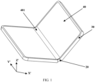
- the terminal device includes a housing 30, a flexible display screen 40, and the rotating shaft assembly 10 described in any one of the foregoing embodiments.
- the flexible display screen 40 is connected to the housing 30, the flexible display screen 40 includes a bending region 401, the rotating shaft assembly 10 is located on a non-display side of the flexible display screen 40, and the rotating shaft assembly 10 is disposed in a correspondence with the bending region 401.
- the terminal device may be a terminal device with a foldable screen effect, such as a mobile phone, a tablet computer, a notebook computer, or a watch.
- the terminal device with the foldable screen effect implements a closed state and an unfolded state by using the rotating shaft assembly 10.
- two swinging parts 42 of two swing arms 4 in the rotating shaft assembly 10 are horizontally placed, to maintain flatness of a surface of the flexible display screen 40.
- the swinging parts 42 of the two swing arms 4 in the rotating shaft assembly 10 are vertically placed, so that the flexible display screen 40 is in a bent state.
- the folding terminal device includes but is not limited to a mobile phone, a tablet computer, an electronic paper, and the like.
- the terminal device is a terminal device with a foldable screen.
- the rotating shaft assembly 10 included in the terminal device provided in this embodiment of this application, because at least a portion of a first surface 411 and at least a portion of a second surface 412 are staggered in a direction of a rotation axis L of the swinging part 42, that is, at least one first surface 411 and at least one second surface 412 are located at different positions of a rotating part 41, the rotating shaft assembly 10 is subjected to external force, and when the rotating part 41 is in contact with a first portion 2 or a second portion 3, a force-bearing surface of the rotating part 41 relative to the first portion 2 and a force-bearing surface of the rotating part 41 relative to the second portion 3 are located at different positions, and therefore, force borne by the rotating part 41, force borne by the first portion 2, and force borne by the second portion 3 are relatively scattered, so that force borne by the rotating part 41 on the first surface 411 and the second surface 412 is relatively small, and force borne by a side surface that is of the first portion 2 and that is
- first surface 411 because the second portion 3 is not subjected to force in this region, rigidity required for the second portion 3 on the first surface 411 is relatively small, and a thickness of the second portion 3 may be correspondingly reduced; and on the second surface 412, because the first portion 2 is not subjected to force in this region, required rigidity on the second surface 412 is relatively small, and a thickness of the first portion 2 may also be correspondingly reduced.
- rigidity of the rotating shaft assembly 10 does not need to be increased by increasing a thickness of the swing arm 4, the thickness of the first portion 2, and the thickness of the second portion 3, so that a thickness and a volume of the rotating shaft assembly 10 can be reduced, and a space occupancy rate of the rotating shaft assembly 10 in the terminal device can be reduced.
Landscapes
- Engineering & Computer Science (AREA)
- Theoretical Computer Science (AREA)
- Computer Hardware Design (AREA)
- General Engineering & Computer Science (AREA)
- Physics & Mathematics (AREA)
- General Physics & Mathematics (AREA)
- Signal Processing (AREA)
- Human Computer Interaction (AREA)
- Mechanical Engineering (AREA)
- Telephone Set Structure (AREA)
- Pivots And Pivotal Connections (AREA)
Abstract
Description
- This application claims priority to
Chinese patent application No. 202211185813.3, filed with the China National Intellectual Property Administration on September 27, 2022 - This application relates to the field of rotating shaft technologies, and in particular, to a rotating shaft assembly and a terminal device.
- A rotating shaft assembly is an important component in a terminal device with a foldable screen effect, such as a mobile phone or a tablet computer. In a related technology, a rotating shaft assembly includes a base and a swing arm that is rotatably connected to the base. To enable the swing arm and the base to have relatively good rigidity, a thickness of the base and a thickness of the swing arm are relatively large, and consequently, an overall thickness and an overall volume of the rotating shaft assembly are relatively large, and relatively large space is occupied when the rotating shaft assembly is used in the terminal device.
- Embodiments of this application are to provide a rotating shaft assembly and a terminal device, to reduce a thickness and a volume of the rotating shaft assembly and reduce a space occupancy rate of the rotating shaft assembly in the terminal device.
- An embodiment of a first aspect of this application provides a rotating shaft assembly, and the rotating shaft assembly includes:
- a base, where the base includes a first portion and a second portion that are fixedly connected, and a first sliding groove is formed between the first portion and the second portion; and
- a swing arm, where the swing arm includes a rotating part and a swinging part, the rotating part is slidably connected to the first sliding groove, and when the rotating part slides relative to the first sliding groove, the swinging part rotates relative to the base; where
- the rotating part includes at least one first surface and at least one second surface, the at least one first surface is disposed opposite to a side surface of the first portion, the at least one second surface is disposed opposite to a side surface of the second portion, and along a rotation axis of the swinging part, at least a portion of the first surface and at least a portion of the second surface are staggered.
- In some embodiments, there are at least two swing arms, the at least two swing arms include a first swing arm and a second swing arm, and a swinging part of the first swing arm and a swinging part of the second swing arm are disposed on two sides of the base.
- In some embodiments, the rotating shaft assembly further includes a shaft cover, and the shaft cover is connected to the base.
- In some embodiments, the rotating part includes two first surfaces, and the at least one second surface is located between the two first surfaces along the rotation axis of the swinging part.
- In some embodiments, the first portion includes a first body part and two connecting parts located on two sides of the first body part, each connecting part includes two pressing blocks, each first surface is disposed opposite to a third surface of one pressing block, and the third surface is a side surface that is of the pressing block and that faces the second portion.
- In some embodiments, each connecting part further includes a connecting member, and the connecting member is connected to the two pressing blocks.
- In some embodiments, the connecting member is in a strip shape, a first strip groove is disposed on a side surface that is of the rotating part and that is away from the shaft cover, the first strip groove extends in a length direction of the connecting member, and at least a partial structure of the connecting member is disposed in the first strip groove.
- In some embodiments, a first concave part is disposed on a side surface that is of the rotating part and that is away from the rotation axis of the swinging part, at least a partial structure of the pressing block is disposed in the first concave part, and a bottom wall of the first concave part includes the first surface.
- In some embodiments, a second concave part is disposed on a side surface that is of the rotating part and that faces the rotation axis of the swinging part, a first convex part is disposed on the second portion, at least a partial structure of the first convex part extends into the second concave part, and a bottom wall of the second concave part includes the second surface.
- In some embodiments, a first limiting block is disposed on the bottom wall of the second concave part, and the first limiting block is located on a side that is of the rotating part and that is away from the swinging part; and
a third concave part is disposed on a side surface that is of the first convex part and that faces the second concave part, and at least a partial structure of the first limiting block is disposed in the third concave part. - In some embodiments, a first through hole is disposed on the swinging part, and when at least two swing arms are in an unfolded state, an end part of the second portion extends into the first through hole in a thickness direction of the rotating shaft assembly.
- In some embodiments, a swinging part of the first swing arm and a swinging part of the second swing arm are symmetrically disposed on two sides of the base.
- In some embodiments, both the at least one first surface and the at least one second surface are arc-shaped surfaces.
- In some embodiments, both the at least one first surface and the at least one second surface are circular arc surfaces, and a central axis of the at least one first surface coincides with a central axis of the at least one second surface.
- In some embodiments, a thickness of the rotating part varies in a radial direction.
- In some embodiments, at least a partial structure of the rotating part is disposed in the first sliding groove.
- In some embodiments, the first portion and the second portion are an integral structure.
- In some embodiments, a manner of connecting the first portion and the second portion includes at least one of a welding connection, a bonding connection, a screw connection, and a nut connection.
- An embodiment of a second aspect of this application provides a terminal device. The terminal device includes a housing, a flexible display screen, and the rotating shaft assembly according to any item above, where the flexible display screen is connected to the housing, the flexible display screen includes a bending region, the rotating shaft assembly is located on a non-display side of the flexible display screen, and the rotating shaft assembly is disposed in a correspondence with the bending region.
- In some embodiments, the terminal device is a terminal device with a foldable screen.
- Beneficial effects of embodiments of this application are as follows:
- In the rotating shaft assembly provided in the embodiments of this application, the first sliding groove is formed between the first portion and the second portion of the base, and the rotating part of the swing arm is slidably connected to the base by using the first sliding groove. The swinging part is disposed outside the first sliding groove, and the swinging part rotates relative to the base in a process in which the rotating part slides relative to the first sliding groove. Because at least a portion of the first surface and at least a portion of the second surface are staggered along the rotation axis of the swinging part, that is, the first surface and the second surface are located at different positions of the rotating part, the rotating shaft assembly is subjected to external force, and when the rotating part is in contact with the first portion or the second portion, a force-bearing surface of the rotating part relative to the first portion and a force-bearing surface of the rotating part relative to the second portion are located at different positions, and therefore, force borne by the rotating part, force borne by the first portion, and force borne by the second portion are relatively scattered, so that force borne by the rotating part on the first surface and the second surface is relatively small, and force borne by a side surface that is of the first portion and that is opposite to the first surface and force borne by a side surface that is of the second portion and that is opposite to the second surface are relatively small. Therefore, rigidity of the rotating shaft assembly does not need to be increased by increasing a thickness of the swing arm, a thickness of the first portion, and a thickness of the second portion, so that a thickness and a volume of the rotating shaft assembly can be reduced, and a space occupancy rate of the rotating shaft assembly in the terminal device can be reduced.
- Certainly, any product or method for implementing this application does not necessarily need to simultaneously achieve all the foregoing advantages.
- To describe technical solutions of embodiments of this application or the prior art more clearly, the following briefly describes the accompanying drawings that need to be used for describing the embodiments or the prior art. Apparently, the accompanying drawings in the following descriptions are merely some embodiments of this application, and a person of ordinary skill in the art may still derive other embodiments based on these accompanying drawings.
-
FIG. 1 is a diagram of a structure of a terminal device according to some embodiments of this application; -
FIG. 2 is a diagram of a structure of a rotating shaft assembly in an unfolded state according to some embodiments of this application; -
FIG. 3 is a diagram of a structure of a rotating shaft assembly in a closed state according to some embodiments of this application; -
FIG. 4 is a diagram of an exploded structure of a rotating shaft assembly according to some embodiments of this application; -
FIG. 5 is a cross-sectional view of a rotating shaft assembly in a direction A-A inFIG. 2 ; -
FIG. 6 is a cross-sectional view of a rotating shaft assembly in an unfolded state in a direction B-B inFIG. 2 according to some embodiments of this application; -
FIG. 7 is a cross-sectional view of a rotating shaft assembly in a closed state in a direction B-B inFIG. 2 according to some embodiments of this application; -
FIG. 8 is a cross-sectional view of a rotating shaft assembly in an unfolded state in a direction C-C inFIG. 2 according to some embodiments of this application; -
FIG. 9 is a cross-sectional view of a rotating shaft assembly in a closed state in a direction C-C inFIG. 2 according to some embodiments of this application; -
FIG. 10 is a diagram of another structure of a rotating shaft assembly according to some embodiments of this application; -
FIG. 11 is a cross-sectional view of the rotating shaft assembly inFIG. 10 in a direction A'-A'; -
FIG. 12 is a cross-sectional view of the rotating shaft assembly inFIG. 10 in a direction C'-C'; -
FIG. 13 is a front view of a rotating shaft assembly according to some embodiments of this application; -
FIG. 14 is a diagram of a structure of a base according to some embodiments of this application; -
FIG. 15 is a diagram of a structure of a swing arm according to some embodiments of this application; -
FIG. 16 is a diagram of another structure of a swing arm according to some embodiments of this application; -
FIG. 17 is a diagram of a structure of another swing arm according to some embodiments of this application; -
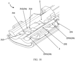
FIG. 18 is a diagram of a partial structure of a base according to some embodiments of this application; -
FIG. 19 is a diagram of a structure of still another swing arm according to some embodiments of this application; -
FIG. 20 is a diagram of a structure of a swing arm mounted on a terminal device shown inFIG. 19 ; and -
FIG. 21 is a diagram of a structure of a swing arm in a comparison example. - The technical solutions in embodiments of this application are clearly and completely described in the following with reference to the accompanying drawings in the embodiments of this application. Apparently, the described embodiments are merely some rather than all of the embodiments of this application. Based on the embodiments of this application, all other embodiments obtained by a person of ordinary skill in the art based on this application fall within the protection scope of this application.
- It should be understood that the terms used herein are intended only for the purpose of describing specific example implementations and are not intended to be limited. As used herein, the singular forms "a", "an", and "the" are intended to include the plural forms as well, unless the context clearly indicates otherwise. The terms "include", "comprise", "contain", and "have" are inclusive and therefore indicate the existence of a stated feature, step, operation, element, and/or component, but do not rule out the existence or addition of one or more other features, steps, operations, elements, components, and/or combinations thereof. The method steps, processes, and operations described herein are not to be construed as requiring them to be executed in the specified order described or illustrated, unless the order of execution is explicitly indicated. It should also be understood that an additional or alternative step may be used.
- It should be understood that although terms such as first, second, and third are used in this specification to describe various elements, components, regions, layers, and/or segments, the elements, components, regions, layers, and/or segments are not limited by these terms. These terms are merely used to distinguish one element, component, region, layer, or segment from another element, component, region, layer, or segment. Terms such as "first" and "second" and other numeric terms are not intended to imply a sequence or an order when being used in this specification unless expressly stated by the context. Therefore, a first element, component, region, layer, or segment discussed below may be referred to as a second element, component, region, layer, or segment without departing from the teachings of the example implementations.
- For ease of description, a spatial relational term may be used in this specification to describe a relationship between one element or feature shown in the figure and another element or feature. These relational terms are, for example, "interior", "exterior", "inner side", "outer side", "under", "below", "on, and "above". It should be understood that such spatial relational terms are intended to include different orientations of a used or operated apparatus in addition to orientations depicted in the figures. For example, if the apparatus in the figure is reversed, an element described as "under another element or feature" or "below another element or feature" is then directed to "on another element or feature" or "above another element or feature". Therefore, an example term "below ..."may be included in orientations "on" and "under". The apparatus may be otherwise directed, for example, is rotated by 90 degrees or in another direction, and a spatial relative relationship descriptor used herein is correspondingly explained.
- To reduce a thickness and a volume of a rotating shaft assembly and reduce a space occupancy rate of the rotating shaft assembly in a terminal device, embodiments of this application provide a rotating shaft assembly and a terminal device. The rotating shaft assembly and the terminal device that are provided in the embodiments of this application are described in detail below with reference to the accompanying drawings. The rotating shaft assembly may be used in a terminal device with a foldable screen effect, such as a mobile phone, a tablet computer, a notebook computer, and a watch, and the rotating shaft assembly may be further used in another device that uses a rotating shaft or a hinge. This is not limited in this application.
- As shown in
FIG. 2 to FIG. 14 , an embodiment of a first aspect of this application provides arotating shaft assembly 10. Therotating shaft assembly 10 includes abase 1 and aswing arm 4, thebase 1 includes afirst portion 2 and asecond portion 3 that are fixedly connected, and a first slidinggroove 21 is formed between thefirst portion 2 and thesecond portion 3. Theswing arm 4 includes arotating part 41 and a swingingpart 42. Therotating part 41 is slidably connected to the first slidinggroove 21. When therotating part 41 slides relative to the first slidinggroove 21, the swingingpart 42 rotates relative to thefirst portion 2. Therotating part 41 includes at least onefirst surface 411 and at least onesecond surface 412, the at least onefirst surface 411 is disposed opposite to a side surface of thefirst portion 2, the at least onesecond surface 412 is disposed opposite to a side surface of thesecond portion 3, and as shown inFIG. 5 , along a rotation axis L of the swingingpart 42, at least a portion of thefirst surface 411 and at least a portion of thesecond surface 412 are staggered. - In this embodiment of this application, as shown in
FIG. 2 ,FIG. 3 , andFIG. 10 , a width direction of therotating shaft assembly 10 is defined as an X direction, a length direction of therotating shaft assembly 10 is defined as a Y direction, and a thickness direction of therotating shaft assembly 10 is defined as a Z direction. An extension direction of the rotation axis L of the swingingpart 42 in therotating shaft assembly 10 is parallel to the length direction Y of therotating shaft assembly 10, and the extension direction of the rotation axis L of the swingingpart 42 in therotating shaft assembly 10 is perpendicular to the width direction Y and the thickness direction Z of therotating shaft assembly 10. As shown inFIG. 1 andFIG. 2 , when therotating shaft assembly 10 is mounted on a terminal device, the width direction X of therotating shaft assembly 10 is a width direction X' of the terminal device, the length direction Y of therotating shaft assembly 10 is a length direction Y' of the terminal device, and the thickness direction Z of therotating shaft assembly 10 is a thickness direction Z' of the terminal device. For ease of description, when therotating shaft assembly 10 is defined to be mounted on a display device, a direction facing a display screen in the display device is up, and a direction away from the display screen in the display device is down. - In this embodiment of this application, along the rotation axis L of the swinging
part 42, that is, in the extension direction parallel to the rotation axis L of the swingingpart 42, in the at least onefirst surface 411 and the at least onesecond surface 412, at least a portion of eachfirst surface 411 and at least a portion of eachsecond surface 412 are staggered. In other words, in the thickness direction Z of therotating shaft assembly 10, an orthographic projection of the at least onefirst surface 411 does not overlap or partially overlap an orthographic projection of the at least onesecond surface 412. - Optionally, as shown in
FIG. 5 andFIG. 11 , eachfirst surface 411 and eachsecond surface 412 are staggered along the rotation axis L of the swingingpart 42; in other words, the orthographic projection of the at least onefirst surface 411 does not overlap the orthographic projection of the at least onesecond surface 412 in the thickness direction Z of therotating shaft assembly 10. - Optionally, a partial structure of each
first surface 411 and a partial structure of eachsecond surface 412 are staggered along the rotation axis L of the swingingpart 42; in other words, the orthographic projection of the at least onefirst surface 411 overlaps the orthographic projection of the at least onesecond surface 412 in the thickness direction Z of therotating shaft assembly 10. Optionally, in the length direction Y of therotating shaft assembly 10, an orthographic projection of an edge of thefirst surface 411 in the thickness direction Z overlaps an orthographic projection of an edge of asecond surface 412 adjacent to thefirst surface 411 in the thickness direction Z. - Optionally, both the at least one
first surface 411 and the at least onesecond surface 412 are arc-shaped surfaces. Optionally, as shown inFIG. 14 ,FIG. 15 ,FIG. 16 , andFIG. 18 , thefirst portion 2 includes afourth surface 24. In the thickness direction Z, thefourth surface 24 is disposed opposite to thefirst surface 411; in other words, in the thickness direction Z, an orthographic projection of thefourth surface 24 covers the orthographic projection of thefirst surface 411. Thesecond portion 3 includes afifth surface 34. In the thickness direction Z, thefifth surface 34 is disposed opposite to thesecond surface 412; in other words, in the thickness direction Z, an orthographic projection of thefifth surface 34 covers the orthographic projection of thesecond surface 412. The first slidinggroove 21 is jointly formed by a first sidewall (an upper sidewall) and a second sidewall (a lower sidewall) in the thickness direction Z and two bottom walls in the length direction Y. Thefourth surface 24 may be used as the first sidewall of the first slidinggroove 21, and thefifth surface 34 may be used as the second sidewall of the first slidinggroove 21. The two bottom walls of the first slidinggroove 21 are respectively disposed opposite to the two sidewalls of therotating part 41 in the length direction Y. - The
first surface 411 is a region that is on therotating part 41 and that is in contact with thefirst portion 2 and exerts upward pressure on thefirst portion 2 when theswing arm 4 is subjected to external force. For example, when theswing arm 4 is subjected to upward pulling force, thefirst surface 411 of therotating part 41 in theswing arm 4 is in contact with thefourth surface 24 of thefirst portion 2, and upward pressure is exerted on thefirst portion 2 on thefirst surface 411. Thesecond surface 412 is a region that is on therotating part 41 and that is in contact with thesecond portion 3 and exerts downward pressure on thesecond portion 3 when theswing arm 4 is subjected to external force. For example, when theswing arm 4 is subjected to downward extrusion force, thesecond surface 412 of therotating part 41 in theswing arm 4 is in contact with thefifth surface 34 of thesecond portion 3, and downward pressure is exerted on thesecond portion 3 on thesecond surface 412. - In a comparison example, as shown in
FIG. 16 ,FIG. 18 , andFIG. 21 , therotating part 41 includes twofirst surfaces 411 and asixth surface 410 that connects the twofirst surfaces 411. When theswing arm 4 inFIG. 21 is mounted on thebase 1, because the twofirst surfaces 411 are disposed opposite to thefourth surface 24 of thefirst portion 2, and thesixth surface 410 is not disposed opposite to thefourth surface 24 of thefirst portion 2, thesixth surface 410 does not meet a definition of thefirst surface 411 in this application, and thesixth surface 410 does not belong to thefirst surface 411. - In the
rotating shaft assembly 10 provided in this embodiment of this application, because at least a portion of thefirst surface 411 and at least a portion of thesecond surface 412 are staggered along the rotation axis L of the swingingpart 42, that is, at least onefirst surface 411 and at least onesecond surface 412 are located at different positions of therotating part 41, the rotatingshaft assembly 10 is subjected to external force, and when therotating part 41 is in contact with thefirst portion 2 or thesecond portion 3, a force-bearing surface of therotating part 41 relative to thefirst portion 2 and a force-bearing surface of therotating part 41 relative to thesecond portion 3 are located at different positions, and therefore, force borne by therotating part 41, force borne by thefirst portion 2, and force borne by thesecond portion 3 are relatively scattered, so that force borne by therotating part 41 on thefirst surface 411 and thesecond surface 412 is relatively small, and force borne by a side surface that is of thefirst portion 2 and that is opposite to thefirst surface 411 and force borne by a side surface that is of thesecond portion 3 and that is opposite to thesecond surface 412 are also relatively small. Specifically, on thefirst surface 411, because thesecond portion 3 is not subjected to force in this region, rigidity required for thesecond portion 3 on thefirst surface 411 is relatively small, and a thickness of thesecond portion 3 may be correspondingly reduced; and on thesecond surface 412, because thefirst portion 2 is not subjected to force in this region, required rigidity on thesecond surface 412 is relatively small, and a thickness of thefirst portion 2 may also be correspondingly reduced. Therefore, rigidity of therotating shaft assembly 10 does not need to be increased by increasing a thickness of theswing arm 4, the thickness of thefirst portion 2, and the thickness of thesecond portion 3, so that a thickness and a volume of therotating shaft assembly 10 can be reduced, and a space occupancy rate of therotating shaft assembly 10 in the terminal device can be reduced. In addition, because therotating shaft assembly 10 has a relatively small thickness and volume, when therotating shaft assembly 10 is used in a terminal device such as a mobile phone with a foldable screen, space occupied by therotating shaft assembly 10 is relatively small, and this facilitates miniaturization and lightening of the terminal device. - A quantity and an area of the
first surface 411 may be set based on an actual requirement, and a quantity and an area of thesecond surface 412 may also be set based on an actual requirement. This is not limited in this application. - In some embodiments, the rotating
shaft assembly 10 further includes ashaft cover 20, and theshaft cover 20 is connected to thebase 1. As shown inFIG. 2 , theshaft cover 20 has accommodating space, and partial structures of thefirst portion 2 and thesecond portion 3 are disposed in theshaft cover 20. When therotating shaft assembly 10 is mounted on the terminal device, theshaft cover 20 may be used as a partial structure of ahousing 30 of the terminal device, or theshaft cover 20 is configured to be connected to thehousing 30 of the terminal device. Theshaft cover 20 may be connected only to thefirst portion 2 or thesecond portion 3 of thebase 1, or theshaft cover 20 may be connected to both thefirst portion 2 and thesecond portion 3. - Optionally, the
base 1 and theshaft cover 20 may be connected by being locked by a fastener, and the fastener includes but is not limited to a screw, a bolt, a nut, and the like. Optionally, thebase 1 and theshaft cover 20 may be connected through welding or bonding. - In some embodiments, there are at least two
swing arms 4, the at least twoswing arms 4 include a first swing arm and a second swing arm, and a swinging part of the first swing arm and a swinging part of the second swing arm are disposed on two sides of thebase 1. - In this embodiment of this application, a structure of the first swing arm is the same as a structure of the second swing arm, the structure of the first swing arm and the structure of the second swing arm are the same as a structure of the
swing arm 4, and the swinging part of the first swing arm and the swinging part of the second swing arm are respectively disposed on two sides of thebase 1 in the width direction X. A quantity of first swing arms may be equal to a quantity of second swing arms, or the quantity of first swing arms may not be equal to the quantity of second swing arms. This is not limited in this application. The swinging part of the first swing arm and the swinging part of the second swing arm are disposed on the two sides of thebase 1, so that when therotating shaft assembly 10 is used in the terminal device, the first swing arm and the second swing arm may drive middle frames, in a terminal apparatus, on two sides of therotating shaft assembly 10 to rotate synchronously. - Optionally, the swinging part of the first swing arm and the swinging part of the second swing arm are symmetrically disposed on the two sides of the
base 1. The quantity of first swing arms and the quantity of second swing arms may be equal, and each first swing arm is disposed in a correspondence with one second swing arm. Swinging parts of a first swing arm and a second swing arm that are disposed in a correspondence are symmetrically disposed on the two sides of thebase 1 in the width direction X, so that when therotating shaft assembly 10 is subjected to external force, a force-bearing situation of the swinging part of the first swing arm is similar to a force-bearing situation of the swingingpart 42 of the second swing arm, and the swinging part of the first swing arm and the swinging part of the second swing arm rotate synchronously. - For ease of description, the rotating
shaft assembly 10 provided in this embodiment of this application is described below by using an example in which therotating shaft assembly 10 includes twoswing arms 4, that is, the rotatingshaft assembly 10 includes one first swing arm and one second swing arm, and swingingparts 42 of the twoswing arms 4 are respectively disposed on the two sides of thebase 1. - In some embodiments, at least a partial structure of the
rotating part 41 is disposed in the first slidinggroove 21, to be slidably connected to the first slidinggroove 21. - Optionally, the
rotating part 41 and the swingingpart 42 are an integral structure. As shown inFIG. 2 andFIG. 10 , when rotatingparts 41 of the twoswing arms 4 are disposed in the first slidinggroove 21, the two swingingparts 42 are located on two sides that are of the tworotating parts 41 and that are away from each other. In a process in which therotating part 41 slides relative to thefirst portion 2 and thesecond portion 3, the swingingpart 42 rotates relative to thefirst portion 2 and thesecond portion 3. - In this embodiment of this application, the rotating
shaft assembly 10 includes an unfolded state and a closed state. As shown inFIG. 2 ,FIG. 3 ,FIG. 6 , and -
FIG. 7, FIG. 6 is a cross-sectional view of therotating shaft assembly 10 in the unfolded state in a direction B-B inFIG. 2 , andFIG. 7 is a cross-sectional view of therotating shaft assembly 10 in the closed state in B-B inFIG. 2 . As shown inFIG. 2 andFIG. 7 , when therotating shaft assembly 10 is in the unfolded state, the two swingingparts 42 are away from each other and are approximately placed horizontally. As shown inFIG. 3 andFIG. 6 , when therotating shaft assembly 10 is in the closed state, the two swingingparts 42 are close to each other and are approximately placed vertically. In a process in which therotating shaft assembly 10 is switched from the unfolded state to the closed state, both the tworotating parts 41 slide relative to thefirst portion 2 and thesecond portion 3, sides that are of the tworotating parts 41 and that are away from the swingingparts 42 move in directions away from each other, and sides that are of the two swingingparts 42 and that are away from therotating parts 41 rotate in directions approaching each other. In a process in which therotating shaft assembly 10 is switched from the closed state to the unfolded state, both the tworotating parts 41 slide relative to thefirst portion 2 and thesecond portion 3, sides that are of the tworotating parts 41 and that are away from the swingingparts 42 move in directions approaching each other, and sides that are of the two swingingparts 42 and that are away from therotating part 41 rotate in directions away from each other. - Optionally, a rotation range of each swinging
part 42 from the unfolded state to the closed state may be 85 degrees to 95 degrees. In an example, the rotation range of each swingingpart 42 from the unfolded state to the closed state may be 90 degrees. - In some embodiments, the
rotating part 41 has twofirst surfaces 411, and along the vertical rotation axis L that is perpendicular to the swingingpart 42, an orthographic projection of at least onesecond surface 412 is located between orthographic projections of the twofirst surfaces 411. - In this embodiment of this application, as shown in
FIG. 5 , eachrotating part 41 has twofirst surfaces 411 with thefirst portion 2. When theswing arm 4 is subjected to upward pulling force, therotating part 41 exerts upward pressure on thefirst portion 2 separately by using the twofirst surfaces 411, so that pressure exerted by therotating part 41 on thefirst portion 2 can be further distributed, thereby further helping reduce a thickness of theswing arm 4 and a thickness of thefirst portion 2. In addition, in the thickness direction Z of therotating shaft assembly 10, the orthographic projections of the twofirst surfaces 411 are located on two sides of the orthographic projection of the at least onesecond surface 412, so that force-bearing surfaces of therotating parts 41 relative to thesecond portion 3 are located between force-bearing surfaces of therotating parts 41 relative to thefirst portion 2 in the rotation axis L of the swingingpart 42, and therefore, force bearing of therotating parts 41 is more uniform. - Optionally, as shown in
FIG. 5 , the twofirst surfaces 411 are symmetrically distributed on two sides of thesecond surface 412. - Optionally, as shown in
FIG. 2 andFIG. 5 , in the length direction Y of therotating shaft assembly 10, the twofirst surfaces 411 are respectively disposed near two side edges of therotating part 41, and the twofirst surfaces 411 respectively include the two side edges of therotating part 41, so that in a process in which therotating part 41 slides in the first slidinggroove 21, thefirst portion 2 can limit the two side edges of therotating part 41 that are prone to shaking, thereby increasing stability in a sliding process of therotating part 41. - In some embodiments, the
first portion 2 includes afirst body part 22 and two connectingparts 23 on two sides of thefirst body part 22. The two connectingparts 23 include twopressing blocks 231. Eachfirst surface 411 is disposed opposite to athird surface 2311 of onepressing block 231, and thethird surface 2311 is a side surface that is of thepressing block 231 and that faces thesecond portion 3. - In this embodiment of this application, as shown in
FIG. 10, FIG. 11 , and -
FIG. 12 ,FIG. 10 is a diagram of a structure of arotating shaft assembly 10 according to an embodiment of this application,FIG. 11 is a cross-sectional view of therotating shaft assembly 10 inFIG. 10 in a direction A'-A', andFIG. 12 is a cross-sectional view of therotating shaft assembly 10 inFIG. 10 in a direction C'-C'. Thefirst portion 2 includes two connectingparts 23 and afirst body part 22 located between the two connectingparts 23. Thefirst body part 22 may be a middle portion of thefirst portion 2, as shown inFIG. 14 . Each connectingpart 23 includes twopressing blocks 231. As shown inFIG. 14 ,FIG. 15 ,FIG. 16 , andFIG. 18 ,third surfaces 2311 of the twopressing blocks 231 are respectively disposed opposite to twofirst surfaces 411 of therotating part 41. Correspondingly, thefirst portion 2 includes twofourth surfaces 24, and thefourth surface 24 of thefirst portion 2 forms athird surface 2311 of thepressing block 231. - When the
swing arm 4 is subjected to upward pulling force, thefirst portion 2 exerts downward pressure on therotating part 41 by using the twopressing blocks 231, and the twofirst surfaces 411 can disperse pressure exerted by thefirst portion 2 on therotating part 41 and force exerted by therotating part 41 on thefirst portion 2, thereby further helping reduce the thickness of theswing arm 4 and the thickness of thefirst portion 2. - In this embodiment of this application, a first sliding sub-groove is formed between each
pressing block 231 and thesecond portion 3, two first sliding sub-grooves formed by the twopressing blocks 231 and thesecond portion 3 form the first slidinggroove 21, and openings of the two first sliding sub-grooves are opposite to each other. In the length direction Y of therotating shaft assembly 10, two sides of therotating part 41 are respectively disposed in the two first sliding sub-grooves, and are slidably connected to the two first sliding sub-grooves. - In some embodiments, as shown in
FIG. 14 andFIG. 18 , each connectingpart 23 further includes a connectingmember 232, and the connectingmember 232 is connected to the twopressing blocks 231. - In this embodiment of this application, the connecting
member 232 is used to increase rigidity of thefirst portion 2, and the connectingmember 232 is further configured to further limit theswing arm 4 in a vertical direction, to reduce a probability that theswing arm 4 is detached from the first slidinggroove 21 in a rotating process. Optionally, the connectingmember 232 may be a beam. - In some embodiments, the connecting
member 232 is in a strip shape. As shown inFIG. 15 , afirst strip groove 416 is disposed on a side surface that is of therotating part 41 and that is away from theshaft cover 20, thefirst strip groove 416 extends in a length direction of the connectingmember 232, and at least a partial structure of the connectingmember 232 is disposed in thefirst strip groove 416. Thefirst strip groove 416 is configured to accommodate the connectingmember 232, so that at least a partial structure of the connectingmember 232 is embedded in therotating part 41. After the connectingmember 232 cooperates with therotating part 41, an overall thickness of therotating part 41 and the connectingmember 232 is reduced, a thickness and a volume of therotating shaft assembly 10 are further reduced, and a space occupancy rate of therotating shaft assembly 10 in the terminal device is reduced. Optionally, all structures of the connectingmember 232 are disposed in thefirst strip groove 416. Optionally, the connectingmember 232 is in a strip shape. - Optionally, each connecting
member 232 and twopressing blocks 231 located at two ends of the connectingmember 232 are an integral structure, and the two connectingparts 23 and thefirst body part 22 are an integral structure. - In this embodiment of this application, the connecting
member 232 may be disposed between the twopressing blocks 231, or the connectingmember 232 may not be disposed between the twopressing blocks 231. This is not limited in this application. Specifically, the connectingmember 232 is not disposed in the connectingpart 23, thefirst strip groove 416 for accommodating the connectingmember 232 does not need to be disposed on therotating part 41 of theswing arm 4, and there is no need to provide accommodating space for the connectingmember 232 by reducing a thickness of therotating part 41. As shown inFIG. 10 ,FIG. 12 , andFIG. 17 , while it is ensured that thefirst portion 2 has relatively good rigidity and an overall thickness of the rotatingassembly 10 is not increased, therotating part 41 has a relatively large thickness, thereby dramatically increasing rigidity of therotating part 41. As shown inFIG. 14 andFIG. 18 , the connectingmember 232 is disposed on the connectingpart 23. The connectingmember 232 can increase rigidity of thefirst portion 2. The connectingmember 232 can further limit theswing arm 4 in the vertical direction, thereby reducing a probability that theswing arm 4 is detached from the first slidinggroove 21 in a rotating process. - Optionally, as shown in
FIG. 2 , a second throughhole 221 is disposed on thefirst body part 22, the second throughhole 221 forms a hollow part on a middle portion of thefirst body part 22, and two ends that are of the tworotating parts 41 and that are close to each other may penetrate the second throughhole 221. The second throughhole 221 may reduce obstruction of thefirst body part 22 for the tworotating parts 41, and increase sliding ranges of the tworotating parts 41, thereby increasing a rotating range of the swingingpart 42. - In some embodiments, a first
concave part 413 is disposed on a side surface that is of therotating part 41 and that is away from theshaft cover 20, at least a partial structure of thepressing block 231 is disposed in the firstconcave part 413, and a bottom wall of the firstconcave part 413 includes thefirst surface 411. - In this embodiment of this application, as shown in
FIG. 2 andFIG. 15 , therotating part 41 includes two firstconcave parts 413 and two first pressingblocks 231, and a partial or entire structure of each firstpressing block 231 is disposed in one firstconcave part 413. As shown inFIG. 2 ,FIG. 14 , andFIG. 15 , the firstconcave part 413 includes afirst sidewall 4131 and afirst bottom wall 4132, thefirst bottom wall 4132 is arc-shaped, and thefirst bottom wall 4132 includes thefirst surface 411. In some embodiments, thefirst surface 411 includes thefirst bottom wall 4132. When at least a partial structure of eachpressing block 231 is disposed in one firstconcave part 413, athird surface 2311 of thepressing block 231 is disposed opposite to thefirst bottom wall 4132 of the firstconcave part 413. - Optionally, as shown in
FIG. 17 , a second convex part is formed between two firstconcave parts 413. An upper surface of therotating part 41, that is, a side surface that is of therotating part 41 and that is opposite to thefirst portion 2, includes twofirst bottom walls 4132 and an upper surface of the second convex part together, and due to the two firstconcave parts 413, the upper surface of therotating part 41 is in a stepped shape. - In this embodiment of this application, at least a partial structure of the
pressing block 231 is disposed in the firstconcave part 413. Thefirst sidewall 4131 of the firstconcave part 413 can limit thepressing block 231, to reduce a probability of displacement of therotating part 41 in a direction parallel to the rotation axis L of the swingingpart 42 in a process in which therotating part 41 slides relative to the first slidinggroove 21, and further increase stability of a connection between therotating part 41 and thefirst portion 2 and a connection between therotating part 41 and thesecond portion 3. Optionally, two sides that are of the two firstconcave parts 413 and that are away from each other extend to an edge of therotating part 41, that is, the two sides that are of the two firstconcave parts 413 and that are away from each other do not have a sidewall, so that therotating part 41 is slidably connected to the first slidinggroove 21 by using the two firstconcave parts 413. - Optionally, as shown in
FIG. 2 andFIG. 5 , when the connectingpart 23 includes the connectingmember 232, there is a gap between an upper surface of the secondconvex part 414 and a lower surface of the connectingmember 232, that is, a lower surface of the secondconvex part 414 is not in contact with an upper surface of the connectingmember 232, so that the upper surface of the secondconvex part 414 and the lower surface of the connectingmember 232 do not need to have relatively high flatness, thereby reducing process difficulty of therotating part 41 and the connectingpart 23, and reducing process difficulty of theswing arm 4 and thefirst portion 2. - In some embodiments, a second
concave part 415 is disposed on a side surface that is of therotating part 41 and that faces theshaft cover 20, a firstconvex part 31 is disposed on thesecond portion 3, the firstconvex part 31 is disposed in the secondconcave part 415, and a bottom wall of the secondconcave part 415 includes thesecond surface 412. - In this embodiment of this application, as shown in
FIG. 15 ,FIG. 16 , and -
FIG. 18 , the secondconcave part 415 includes asecond sidewall 41521, athird sidewall 41522, and a second bottom wall 4153 connected to thesecond sidewall 41521 and thethird sidewall 41522, and the second bottom wall 4153 is arc-shaped. The firstconvex part 31 includes a firsttop wall 312 and afourth sidewall 313 and afifth sidewall 314 on two sides of the firsttop wall 312. The firsttop wall 312 is afifth surface 34 of thesecond portion 3. - When the
rotating part 41 is slidably connected to the first slidinggroove 21, the second bottom wall 4153 is disposed opposite to the firsttop wall 312, thesecond sidewall 41521 is disposed opposite to thefourth sidewall 313, and thethird sidewall 41522 is disposed opposite to thefifth sidewall 314. The second bottom wall 4153 of the secondconcave part 415 includes asecond surface 412. Optionally, thesecond surface 412 includes the second bottom wall 4153. The second bottom wall 4153 of the two secondconcave parts 415 is used as thesecond surface 412 of therotating part 41, and when theswing arm 4 is subjected to downward extrusion force, thesecond portion 3 exerts upward support force on therotating part 41 by using the two firstconvex parts 31, so that support force exerted by thesecond portion 3 on therotating part 41 can be dispersed, thereby helping further reduce the thickness of theswing arm 4 and the thickness of thesecond portion 3. In addition, thesecond sidewall 41521 and thethird sidewall 41522 of the secondconcave part 415 can limit the firstconvex part 31, to limit therotating part 41, thereby reducing a probability of displacement of therotating part 41 in a direction parallel to the rotation axis L of the swingingpart 42 in a process in which therotating part 41 slides relative to the first slidinggroove 21, and further increasing stability of a connection between therotating part 41 and thefirst portion 2 and a connection between therotating part 41 and thesecond portion 3. - Optionally, there is a gap between the
second sidewall 41521 of the secondconcave part 415 and thefourth sidewall 313 of the firstconvex part 31, and there is also a gap between thethird sidewall 41522 of the secondconcave part 415 and thefifth sidewall 314 of the firstconvex part 31; in other words, thesecond sidewall 41521 is not in contact with thefourth sidewall 313, and thethird sidewall 41522 is not in contact with thefifth sidewall 314, so that the sidewall of the secondconcave part 415 and the sidewall of the firstconvex part 31 do not need to have relatively high flatness, and process difficulty of theswing arm 4 and thesecond portion 3 is reduced. - In some embodiments, as shown in
FIG. 2 ,FIG. 15 ,FIG. 16 , andFIG. 17 , a limitingblock 4151 is disposed on the bottom wall of the secondconcave part 415, and the limitingblock 4151 is located on a side that is of therotating part 41 and that is away from the swingingpart 42. A thirdconcave part 311 is disposed on a side surface that is of the firstconvex part 31 and that faces the secondconcave part 415, and the first limitingblock 4151 is disposed in the thirdconcave part 311. - In this embodiment of this application, one first limiting
block 4151 is disposed on eachrotating part 41, the first limitingblock 4151 is disposed in the thirdconcave part 311, and a sidewall that is of the thirdconcave part 311 and that is close to the swingingpart 42 may limit the first limitingblock 4151. Specifically, when twoswing arms 4 are switched from the unfolded state to the closed state, that is, when therotating shaft assembly 10 is switched from the unfolded state to the closed state, a side that is of therotating part 41 in theswing arm 4 and that is away from the swingingpart 42, that is, a front side of therotating part 41, slides from a middle portion of thesecond portion 3 to an edge portion of thesecond portion 3, and asidewall 3111 that is of the thirdconcave part 311 and that is close to the swingingpart 42 can block the first limitingblock 4151, so that the front side of therotating part 41 does not continue to slide after sliding to the edge portion of thesecond portion 3. Based on this, the sidewall that is of the thirdconcave part 311 and that is close to the swingingpart 42 can limit the first limitingblock 4151, to limit a sliding range of the first limitingblock 4151, thereby limiting a sliding range of therotating part 41, and reducing a probability that therotating part 41 is detached from thesecond portion 3 in a sliding process. - In some implementations, a first through
hole 421 is disposed on the swingingpart 42. When at least twoswing arms 4 are in the unfolded state, anend part 33 of thesecond portion 3 extends into the first throughhole 421 in the thickness direction Z of therotating shaft assembly 10. - In this embodiment of this application, as shown in
FIG. 9 , when therotating shaft assembly 10 is in the closed state, endparts 33 on two sides of thesecond portion 3 in the width direction Y can limit therotating part 41, to provide a larger sliding range for therotating part 41, and reduce a probability that the tworotating parts 41 are detached from thesecond portion 3 when sliding relative to thesecond portion 3. In addition, as shown inFIG. 4 andFIG. 8 , when the twoswing arms 4 are in the unfolded state, that is, when therotating shaft assembly 10 is in the unfolded state, endparts 33 on two sides of thesecond portion 3 in the width direction X extend into the first throughhole 421, and the first throughhole 421 is used to accommodate theend part 33 of thesecond portion 3, to reduce impact exerted by theend part 33 of thesecond portion 3 on the swingingpart 42 in a rotating process of theswing arm 4. - In addition, in this embodiment of this application, because the
second portion 3 bears no force on thefirst surface 411, and stiffness required for thesecond portion 3 on thefirst surface 411 is relatively small, a thickness of thesecond portion 3 is correspondingly reduced. Therefore, a thickness of theend part 33 of thesecond portion 3 is also relatively small, so that a horizontal width occupied by theend part 33 of thesecond portion 3 can be reduced, and the volume of therotating shaft assembly 10 can be further reduced. - In some embodiments, the at least one
first surface 411 and the at least onesecond surface 412 are both circular arc surfaces, and the at least onefirst surface 411 coincides with a center axis of the at least onesecond surface 412. - In this embodiment of this application, the
first surface 411 and thesecond surface 412 are circular arc surfaces, and the first slidinggroove 21 is also a circular arc groove, and the circular arc surface and the circular arc groove have no edges or angles, and this helps improve fluency when therotating part 41 slides relative to thefirst portion 2 and thesecond portion 3. In addition, thefirst surface 411 coincides with the center axis of thesecond surface 412, so that a distance between thefirst surface 411 and thesecond surface 412 in the thickness direction remains unchanged in the sliding process of therotating part 41, and stability in a process in which therotating part 41 slides relative to thefirst portion 2 and thesecond portion 3 is improved. - In some embodiments, a thickness of the
rotating part 41 varies in a radial direction. - In this embodiment of this application, the
first surface 411 and thesecond surface 412 are arc surfaces or circular arc surfaces, and a radial direction of therotating part 41 is an extension direction of a radius corresponding to thefirst surface 411 and an extension direction of a radius corresponding to thesecond surface 412. For example, the radial direction is the extension direction of the radius corresponding to thefirst surface 411. Each point on thefirst surface 411 has a corresponding extension direction of a radius, and extension directions of radii corresponding to all points intersect with a center axis corresponding to thefirst surface 411. As shown inFIG. 19 andFIG. 20 , from a side that is of therotating part 41 and that is close to the swingingpart 42 to a side that is of therotating part 41 and that is away from the swingingpart 42, therotating part 41 successively includes afirst segment 417, asecond segment 418, and athird segment 419. A radial thickness of thefirst segment 417 is not equal to a radial thickness of thesecond segment 418, and a radial thickness of thethird segment 419 is not equal to the radial thickness of thesecond segment 418. Optionally, the radial thickness of thesecond segment 418 is less than the radial thickness of thefirst segment 417 and the radial thickness of thethird segment 419. When therotating shaft assembly 10 is in the closed state, thesecond segment 418 may provide avoidance space for other structural components in the terminal device because the radial thickness of thesecond segment 418 is less than the radial thickness of thefirst segment 417 and the radial thickness of thethird segment 419. For example, as shown inFIG. 20 , thesecond segment 418 may provide avoidance space for amiddle frame 310 of thehousing 30 of the terminal device, so that themiddle frame 310 has more design space. - Optionally, a partial structure of a side that is of the
second segment 418 and that is away from thefirst portion 2 may be removed, so that the radial thickness of thesecond segment 418 is less than the radial thickness of thefirst segment 417 and the radial thickness of thethird segment 419. - In some embodiments, the
first portion 2 and thesecond portion 3 are connected as an integral structure. Thefirst portion 2 and thesecond portion 3 may be an integral structure. This facilitates mounting of components in therotating shaft structure 10 and reduces structural complexity of therotating shaft structure 10. - Optionally, a manner of connecting the
first portion 2 and thesecond portion 3 includes at least one of a welding connection, a bonding connection, a screw connection, and a nut connection. - In this embodiment of this application, as shown in
FIG. 12, FIG. 12 is a front view of therotating shaft assembly 10 inFIG. 2 . There is aconnection region 25 on thefirst portion 2 and thethird portion 3, and thefirst portion 2 and thesecond portion 3 are fastened through welding or glue dispensing in theconnection region 25. In addition, apositioning hole 26 is disposed on thefirst portion 2 and thesecond portion 3. In a process of connecting thefirst portion 2 and thesecond portion 3, a fastener such as a bolt may penetrate thepositioning hole 26 first to fixedly connect thefirst portion 2 and thesecond portion 3, and then, thefirst portion 2 and thesecond portion 3 are connected in theconnection region 25 through glue dispensing or welding, and finally, the fastener is removed, and welding precision and bonding precision between thefirst portion 2 and thesecond portion 3 are increased by using thepositioning hole 26 and the fastener. - Optionally, the
first portion 2 and thesecond portion 3 may be alternatively connected by using a fastener such as a bolt. - An embodiment of a second aspect of this application provides a terminal device. As shown in
FIG. 1 , the terminal device includes ahousing 30, aflexible display screen 40, and therotating shaft assembly 10 described in any one of the foregoing embodiments. Theflexible display screen 40 is connected to thehousing 30, theflexible display screen 40 includes abending region 401, the rotatingshaft assembly 10 is located on a non-display side of theflexible display screen 40, and therotating shaft assembly 10 is disposed in a correspondence with the bendingregion 401. - In this embodiment of this application, the terminal device may be a terminal device with a foldable screen effect, such as a mobile phone, a tablet computer, a notebook computer, or a watch. The terminal device with the foldable screen effect implements a closed state and an unfolded state by using the
rotating shaft assembly 10. When the terminal device is in the unfolded state, two swingingparts 42 of twoswing arms 4 in therotating shaft assembly 10 are horizontally placed, to maintain flatness of a surface of theflexible display screen 40. When the terminal device is in a folded state, the swingingparts 42 of the twoswing arms 4 in therotating shaft assembly 10 are vertically placed, so that theflexible display screen 40 is in a bent state. The folding terminal device includes but is not limited to a mobile phone, a tablet computer, an electronic paper, and the like. - In some embodiments, the terminal device is a terminal device with a foldable screen.
- In the rotating shaft assembly 10 included in the terminal device provided in this embodiment of this application, because at least a portion of a first surface 411 and at least a portion of a second surface 412 are staggered in a direction of a rotation axis L of the swinging part 42, that is, at least one first surface 411 and at least one second surface 412 are located at different positions of a rotating part 41, the rotating shaft assembly 10 is subjected to external force, and when the rotating part 41 is in contact with a first portion 2 or a second portion 3, a force-bearing surface of the rotating part 41 relative to the first portion 2 and a force-bearing surface of the rotating part 41 relative to the second portion 3 are located at different positions, and therefore, force borne by the rotating part 41, force borne by the first portion 2, and force borne by the second portion 3 are relatively scattered, so that force borne by the rotating part 41 on the first surface 411 and the second surface 412 is relatively small, and force borne by a side surface that is of the first portion 2 and that is opposite to the first surface 411 and force borne by a side surface that is of the second portion 3 and that is opposite to the second surface 412 are relatively small. Specifically, on the
first surface 411, because thesecond portion 3 is not subjected to force in this region, rigidity required for thesecond portion 3 on thefirst surface 411 is relatively small, and a thickness of thesecond portion 3 may be correspondingly reduced; and on thesecond surface 412, because thefirst portion 2 is not subjected to force in this region, required rigidity on thesecond surface 412 is relatively small, and a thickness of thefirst portion 2 may also be correspondingly reduced. Therefore, rigidity of therotating shaft assembly 10 does not need to be increased by increasing a thickness of theswing arm 4, the thickness of thefirst portion 2, and the thickness of thesecond portion 3, so that a thickness and a volume of therotating shaft assembly 10 can be reduced, and a space occupancy rate of therotating shaft assembly 10 in the terminal device can be reduced. - Finally, it should be noted that: the foregoing embodiments are merely used for describing the technical solutions of this application, but are not intended to limit this application. Although this application is described in detail with reference to the foregoing embodiments, it should be understood by a person of ordinary skill in the art that, modifications may still be made to the technical solutions recorded in the foregoing embodiments, or equivalent replacements may be made to some or all of technical features; and these modifications or replacements do not cause the essence of corresponding technical solutions to depart from the scope of the technical solutions in the embodiments of this application, and are all covered by the scope of the claims and the specification of this application. In particular, provided that there are no structural conflicts, technical features mentioned in the embodiments may be combined in any manner. This application is not limited to specific embodiments of this application, but includes all technical solutions falling within the scope of the claims.
Claims (20)
- A rotating shaft assembly, comprising:a base, wherein the base comprises a first portion and a second portion that are fixedly connected, and a first sliding groove is formed between the first portion and the second portion; anda swing arm, wherein the swing arm comprises a rotating part and a swinging part, the rotating part is slidably connected to the first sliding groove, and when the rotating part slides relative to the first sliding groove, the swinging part rotates relative to the base; whereinthe rotating part comprises at least one first surface and at least one second surface, the at least one first surface is disposed opposite to a side surface of the first portion, the at least one second surface is disposed opposite to a side surface of the second portion, and along a rotation axis of the swinging part, at least a portion of the first surface and at least a portion of the second surface are staggered.
- The rotating shaft assembly according to claim 1, wherein there are at least two swing arms, the at least two swing arms comprise a first swing arm and a second swing arm, and a swinging part of the first swing arm and a swinging part of the second swing arm are disposed on two sides of the base.
- The rotating shaft assembly according to claim 1 or 2, wherein the rotating shaft assembly further comprises a shaft cover, and the shaft cover is connected to the base.
- The rotating shaft assembly according to claim 3, wherein the rotating part comprises two first surfaces, and the at least one second surface is located between the two first surfaces along the rotation axis of the swinging part.
- The rotating shaft assembly according to claim 4, wherein the first portion comprises a first body part and two connecting parts located on two sides of the first body part, each connecting part comprises two pressing blocks, each first surface is disposed opposite to a third surface of one pressing block, and the third surface is a side surface that is of the pressing block and that faces the second portion.
- The rotating shaft assembly according to claim 5, wherein the connecting part further comprises a connecting member, and the connecting member is connected to the two pressing blocks.
- The rotating shaft assembly according to claim 6, wherein the connecting member is in a strip shape, a first strip groove is disposed on a side surface that is of the rotating part and that is away from the shaft cover, the first strip groove extends in a length direction of the connecting member, and at least a partial structure of the connecting member is disposed in the first strip groove.
- The rotating shaft assembly according to any one of claims 5 to 7, wherein a first concave part is disposed on a side surface that is of the rotating part and that is away from the rotation axis of the swinging part, at least a partial structure of the pressing block is disposed in the first concave part, and a bottom wall of the first concave part comprises the first surface.
- The rotating shaft assembly according to any one of claims 1 to 7, wherein a second concave part is disposed on a side surface that is of the rotating part and that faces the rotation axis of the swinging part, a first convex part is disposed on the second portion, at least a partial structure of the first convex part extends into the second concave part, and a bottom wall of the second concave part comprises the second surface.
- The rotating shaft assembly according to claim 9, wherein a first limiting block is disposed on the bottom wall of the second concave part, and the first limiting block is located on a side that is of the rotating part and that is away from the swinging part; and
a third concave part is disposed on a side surface that is of the first convex part and that faces the second concave part, and at least a partial structure of the first limiting block is disposed in the third concave part. - The rotating shaft assembly according to claim 2, wherein a first through hole is disposed on the swinging part, and when at least two swing arms are in an unfolded state, an end part of the second portion extends into the first through hole in a thickness direction of the rotating shaft assembly.
- The rotating shaft assembly according to claim 2, wherein a swinging part of the first swing arm and a swinging part of the second swing arm are symmetrically disposed on two sides of the base.
- The rotating shaft assembly according to any one of claims 1 to 12, wherein both the first surface and the second surface are arc-shaped surfaces.
- The rotating shaft assembly according to any one of claims 1 to 12, wherein both the first surface and the second surface are circular arc surfaces, and a central axis of the first surface coincides with a central axis of the second surface.
- The rotating shaft assembly according to claim 13 or 14, wherein a thickness of the rotating part varies in a radial direction.
- The rotating shaft assembly according to any one of claims 1 to 15, wherein at least a partial structure of the rotating part is disposed in the first sliding groove.
- The rotating shaft assembly according to any one of claims 1 to 16, wherein the first portion and the second portion are an integral structure.
- The rotating shaft assembly according to any one of claims 1 to 17, wherein a manner of connecting the first portion and the second portion comprises at least one of a welding connection, a bonding connection, a screw connection, and a nut connection.
- A terminal device, wherein the terminal device comprises a housing, a flexible display screen, and the rotating shaft assembly according to any one of claims 1 to 18, wherein the flexible display screen is connected to the housing, the flexible display screen comprises a bending region, the rotating shaft assembly is located on a non-display side of the flexible display screen, and the rotating shaft assembly is disposed in a correspondence with the bending region.
- The terminal device according to claim 19, wherein the terminal device is a terminal device with a foldable screen.
Applications Claiming Priority (2)
| Application Number | Priority Date | Filing Date | Title |
|---|---|---|---|
| CN202211185813.3A CN117780773A (en) | 2022-09-27 | 2022-09-27 | A rotating shaft assembly and terminal device |
| PCT/CN2023/114675 WO2024066830A1 (en) | 2022-09-27 | 2023-08-24 | Rotating shaft assembly and terminal device |
Publications (3)
| Publication Number | Publication Date |
|---|---|
| EP4455498A1 true EP4455498A1 (en) | 2024-10-30 |
| EP4455498A4 EP4455498A4 (en) | 2025-05-07 |
| EP4455498B1 EP4455498B1 (en) | 2026-02-04 |
Family
ID=90385632
Family Applications (1)
| Application Number | Title | Priority Date | Filing Date |
|---|---|---|---|
| EP23870073.6A Active EP4455498B1 (en) | 2022-09-27 | 2023-08-24 | Rotating shaft assembly and terminal device |
Country Status (4)
| Country | Link |
|---|---|
| US (1) | US20250216911A1 (en) |
| EP (1) | EP4455498B1 (en) |
| CN (2) | CN117780773A (en) |
| WO (1) | WO2024066830A1 (en) |
Family Cites Families (5)
| Publication number | Priority date | Publication date | Assignee | Title |
|---|---|---|---|---|
| KR101023495B1 (en) * | 2009-10-06 | 2011-03-21 | (주) 프렉코 | Folding device hinge device |
| KR102375556B1 (en) * | 2019-04-30 | 2022-03-17 | 삼성전자주식회사 | Structure of Hinge and electronic device including the same |
| CN113067924B (en) * | 2021-03-19 | 2023-05-23 | 维沃移动通信有限公司 | Folding mechanism, support structure and electronic equipment |
| CN114500699B (en) * | 2021-08-20 | 2023-03-07 | 荣耀终端有限公司 | Rotating mechanism and foldable terminal |
| CN115013421B (en) * | 2021-11-29 | 2023-04-14 | 荣耀终端有限公司 | Folding mechanism and terminal equipment |
-
2022
- 2022-09-27 CN CN202211185813.3A patent/CN117780773A/en active Pending
-
2023
- 2023-08-24 WO PCT/CN2023/114675 patent/WO2024066830A1/en not_active Ceased
- 2023-08-24 CN CN202380057990.XA patent/CN119654497A/en active Pending
- 2023-08-24 US US18/835,096 patent/US20250216911A1/en active Pending
- 2023-08-24 EP EP23870073.6A patent/EP4455498B1/en active Active
Also Published As
| Publication number | Publication date |
|---|---|
| WO2024066830A1 (en) | 2024-04-04 |
| EP4455498B1 (en) | 2026-02-04 |
| CN117780773A (en) | 2024-03-29 |
| EP4455498A4 (en) | 2025-05-07 |
| CN119654497A (en) | 2025-03-18 |
| US20250216911A1 (en) | 2025-07-03 |
Similar Documents
| Publication | Publication Date | Title |
|---|---|---|
| EP4246941B1 (en) | Folding mechanism | |
| US11832405B2 (en) | Rotating module and electronic device | |
| US12353254B2 (en) | Rotating shaft mechanism and electronic device | |
| EP4215767B1 (en) | Folding mechanism and terminal device | |
| JP7479505B2 (en) | Frame structure, screen components and electronics | |
| EP4283145B1 (en) | Hook mechanism, supporting apparatus, and electronic device | |
| US12625525B2 (en) | Rotating shaft apparatus, foldable housing and electronic device | |
| WO2023231393A1 (en) | Folding device, housing assembly and electronic device | |
| WO2024046096A1 (en) | Folding assembly, folding apparatus and terminal device | |
| EP4455498B1 (en) | Rotating shaft assembly and terminal device | |
| KR101303133B1 (en) | Tilting mechanism and sliding device | |
| CN117189763A (en) | Folding device, shell assembly and electronic equipment | |
| CN117189766A (en) | Folding device, shell assembly and electronic equipment | |
| CN219834182U (en) | Folding assembly and foldable electronic equipment | |
| US20240236217A1 (en) | Damping mechanism and terminal | |
| CN118555322A (en) | Hinge mechanism and electronic device | |
| CN120212142A (en) | Hinge mechanism and foldable electronic device | |
| CN116771789A (en) | Rotating shaft assembly and electronic equipment | |
| CN121358963A (en) | Rotating mechanism and foldable electronic devices | |
| CN218863068U (en) | Hinge applied to portable electronic equipment | |
| CN218863067U (en) | Hinge applied to portable electronic equipment | |
| EP4556727A1 (en) | Sliding mechanism and foldable electronic device | |
| CN119676339A (en) | Folding device, housing assembly and electronic device | |
| CN224079461U (en) | Hinge devices and electronic equipment | |
| WO2026007518A1 (en) | Hinge assembly and electronic device |
Legal Events
| Date | Code | Title | Description |
|---|---|---|---|
| STAA | Information on the status of an ep patent application or granted ep patent |
Free format text: STATUS: THE INTERNATIONAL PUBLICATION HAS BEEN MADE |
|
| PUAI | Public reference made under article 153(3) epc to a published international application that has entered the european phase |
Free format text: ORIGINAL CODE: 0009012 |
|
| STAA | Information on the status of an ep patent application or granted ep patent |
Free format text: STATUS: REQUEST FOR EXAMINATION WAS MADE |
|
| 17P | Request for examination filed |
Effective date: 20240722 |
|
| AK | Designated contracting states |
Kind code of ref document: A1 Designated state(s): AL AT BE BG CH CY CZ DE DK EE ES FI FR GB GR HR HU IE IS IT LI LT LU LV MC ME MK MT NL NO PL PT RO RS SE SI SK SM TR |
|
| REG | Reference to a national code |
Ref country code: DE Ref legal event code: R079 Free format text: PREVIOUS MAIN CLASS: F16C0011040000 Ipc: G06F0001160000 Ref country code: DE Ref legal event code: R079 Ref document number: 602023011723 Country of ref document: DE Free format text: PREVIOUS MAIN CLASS: F16C0011040000 Ipc: G06F0001160000 |
|
| A4 | Supplementary search report drawn up and despatched |
Effective date: 20250403 |
|
| RIC1 | Information provided on ipc code assigned before grant |
Ipc: F16C 11/04 20060101ALI20250328BHEP Ipc: H04M 1/02 20060101ALI20250328BHEP Ipc: G06F 1/16 20060101AFI20250328BHEP |
|
| GRAP | Despatch of communication of intention to grant a patent |
Free format text: ORIGINAL CODE: EPIDOSNIGR1 |
|
| STAA | Information on the status of an ep patent application or granted ep patent |
Free format text: STATUS: GRANT OF PATENT IS INTENDED |
|
| RIC1 | Information provided on ipc code assigned before grant |
Ipc: G06F 1/16 20060101AFI20250825BHEP Ipc: H04M 1/02 20060101ALI20250825BHEP Ipc: F16C 11/04 20060101ALI20250825BHEP Ipc: G09F 9/30 20060101ALI20250825BHEP |
|
| INTG | Intention to grant announced |
Effective date: 20250918 |
|
| GRAS | Grant fee paid |
Free format text: ORIGINAL CODE: EPIDOSNIGR3 |
|
| DAV | Request for validation of the european patent (deleted) | ||
| DAX | Request for extension of the european patent (deleted) | ||
| GRAA | (expected) grant |
Free format text: ORIGINAL CODE: 0009210 |
|
| STAA | Information on the status of an ep patent application or granted ep patent |
Free format text: STATUS: THE PATENT HAS BEEN GRANTED |
|
| AK | Designated contracting states |
Kind code of ref document: B1 Designated state(s): AL AT BE BG CH CY CZ DE DK EE ES FI FR GB GR HR HU IE IS IT LI LT LU LV MC ME MK MT NL NO PL PT RO RS SE SI SK SM TR |
|
| REG | Reference to a national code |
Ref country code: CH Ref legal event code: F10 Free format text: ST27 STATUS EVENT CODE: U-0-0-F10-F00 (AS PROVIDED BY THE NATIONAL OFFICE) Effective date: 20260204 Ref country code: GB Ref legal event code: FG4D |
|
| REG | Reference to a national code |
Ref country code: DE Ref legal event code: R096 Ref document number: 602023011723 Country of ref document: DE |
|
| REG | Reference to a national code |
Ref country code: IE Ref legal event code: FG4D |
|
| REG | Reference to a national code |
Ref country code: NL Ref legal event code: FP |