EP4455465A1 - Offset core with side ejector nacelle nozzles - Google Patents
Offset core with side ejector nacelle nozzles Download PDFInfo
- Publication number
- EP4455465A1 EP4455465A1 EP24173188.4A EP24173188A EP4455465A1 EP 4455465 A1 EP4455465 A1 EP 4455465A1 EP 24173188 A EP24173188 A EP 24173188A EP 4455465 A1 EP4455465 A1 EP 4455465A1
- Authority
- EP
- European Patent Office
- Prior art keywords
- condenser
- fan
- flow
- core engine
- duct
- Prior art date
- Legal status (The legal status is an assumption and is not a legal conclusion. Google has not performed a legal analysis and makes no representation as to the accuracy of the status listed.)
- Granted
Links
Images



Classifications
-
- F—MECHANICAL ENGINEERING; LIGHTING; HEATING; WEAPONS; BLASTING
- F02—COMBUSTION ENGINES; HOT-GAS OR COMBUSTION-PRODUCT ENGINE PLANTS
- F02C—GAS-TURBINE PLANTS; AIR INTAKES FOR JET-PROPULSION PLANTS; CONTROLLING FUEL SUPPLY IN AIR-BREATHING JET-PROPULSION PLANTS
- F02C3/00—Gas-turbine plants characterised by the use of combustion products as the working fluid
- F02C3/20—Gas-turbine plants characterised by the use of combustion products as the working fluid using a special fuel, oxidant, or dilution fluid to generate the combustion products
- F02C3/22—Gas-turbine plants characterised by the use of combustion products as the working fluid using a special fuel, oxidant, or dilution fluid to generate the combustion products the fuel or oxidant being gaseous at standard temperature and pressure
-
- F—MECHANICAL ENGINEERING; LIGHTING; HEATING; WEAPONS; BLASTING
- F02—COMBUSTION ENGINES; HOT-GAS OR COMBUSTION-PRODUCT ENGINE PLANTS
- F02C—GAS-TURBINE PLANTS; AIR INTAKES FOR JET-PROPULSION PLANTS; CONTROLLING FUEL SUPPLY IN AIR-BREATHING JET-PROPULSION PLANTS
- F02C3/00—Gas-turbine plants characterised by the use of combustion products as the working fluid
- F02C3/04—Gas-turbine plants characterised by the use of combustion products as the working fluid having a turbine driving a compressor
-
- F—MECHANICAL ENGINEERING; LIGHTING; HEATING; WEAPONS; BLASTING
- F02—COMBUSTION ENGINES; HOT-GAS OR COMBUSTION-PRODUCT ENGINE PLANTS
- F02C—GAS-TURBINE PLANTS; AIR INTAKES FOR JET-PROPULSION PLANTS; CONTROLLING FUEL SUPPLY IN AIR-BREATHING JET-PROPULSION PLANTS
- F02C3/00—Gas-turbine plants characterised by the use of combustion products as the working fluid
- F02C3/20—Gas-turbine plants characterised by the use of combustion products as the working fluid using a special fuel, oxidant, or dilution fluid to generate the combustion products
- F02C3/30—Adding water, steam or other fluids for influencing combustion, e.g. to obtain cleaner exhaust gases
- F02C3/305—Increasing the power, speed, torque or efficiency of a gas turbine or the thrust of a turbojet engine by injecting or adding water, steam or other fluids
-
- F—MECHANICAL ENGINEERING; LIGHTING; HEATING; WEAPONS; BLASTING
- F02—COMBUSTION ENGINES; HOT-GAS OR COMBUSTION-PRODUCT ENGINE PLANTS
- F02C—GAS-TURBINE PLANTS; AIR INTAKES FOR JET-PROPULSION PLANTS; CONTROLLING FUEL SUPPLY IN AIR-BREATHING JET-PROPULSION PLANTS
- F02C7/00—Features, components parts, details or accessories, not provided for in, or of interest apart form groups F02C1/00 - F02C6/00; Air intakes for jet-propulsion plants
- F02C7/12—Cooling of plants
- F02C7/16—Cooling of plants characterised by cooling medium
-
- F—MECHANICAL ENGINEERING; LIGHTING; HEATING; WEAPONS; BLASTING
- F05—INDEXING SCHEMES RELATING TO ENGINES OR PUMPS IN VARIOUS SUBCLASSES OF CLASSES F01-F04
- F05D—INDEXING SCHEME FOR ASPECTS RELATING TO NON-POSITIVE-DISPLACEMENT MACHINES OR ENGINES, GAS-TURBINES OR JET-PROPULSION PLANTS
- F05D2260/00—Function
- F05D2260/20—Heat transfer, e.g. cooling
- F05D2260/213—Heat transfer, e.g. cooling by the provision of a heat exchanger within the cooling circuit
-
- F—MECHANICAL ENGINEERING; LIGHTING; HEATING; WEAPONS; BLASTING
- F05—INDEXING SCHEMES RELATING TO ENGINES OR PUMPS IN VARIOUS SUBCLASSES OF CLASSES F01-F04
- F05D—INDEXING SCHEME FOR ASPECTS RELATING TO NON-POSITIVE-DISPLACEMENT MACHINES OR ENGINES, GAS-TURBINES OR JET-PROPULSION PLANTS
- F05D2260/00—Function
- F05D2260/60—Fluid transfer
- F05D2260/601—Fluid transfer using an ejector or a jet pump
Definitions
- the present disclosure relates generally to an aircraft propulsion system and, more particularly, to a turbine engine including an offset gas generating core engine and nacelle mounted heat exchangers.
- a propulsion system for an aircraft includes, among other possible things, a fan that is rotatable about a fan axis, a core engine that is configured for generating a gas flow utilized to generate shaft power for driving the fan, a nacelle that surrounds the core engine and the fan, a condenser where water in the gas flow is condensed into a liquid form, an exhaust duct assembly where the gas flow exhausted from the core engine is directed to the condenser, an ejector duct where a portion of a bypass airflow is thermally communicated with the condenser to cool the gas flow, and an evaporator assembly that is in thermal communication with the exhaust duct where water recovered by the condenser is heated to generate a steam flow that is subsequently communicated to the core engine.
- the core engine is disposed about a core engine axis that is offset relative to the fan axis.
- the propulsion system includes a power turbine that is coupled to the fan through a driveshaft.
- the gas flow from the core engine is received and expanded through the power turbine to drive the drive shaft.
- the condenser includes a first condenser portion and a second condenser portion that is separate from the first condenser portion.
- a cross-section transverse to the fan axis through either or both of the first condenser portion and the second condenser portion defines a ring sector area.
- a central angle of the ring sector area for either or both of the first condenser portion and the second condenser portion is between 60 degrees and 120 degrees.
- the propulsion system further includes an exhaust case where gas flow from the power turbine is communicated to the exhaust duct assembly.
- the exhaust duct assembly extends radially outward from the exhaust case toward the nacelle.
- the exhaust duct assembly includes a plurality of radial duct parts that extend radially outward from the exhaust case toward the nacelle.
- the evaporator assembly is in thermal communication with at least a portion of the exhaust duct assembly between the exhaust case and the condenser.
- the ejector duct includes an ejector exit opening separate from a fan flow duct opening and radially outward of the fan flow duct opening.
- the ejector duct includes a flow area that increases from an area at an ejector inlet to an area at an outlet to the condenser.
- the flow area of the ejector duct includes a ratio between a flow area at the outlet to the condenser relative to a flow area at the ejector inlet that is between 4 and 20.
- a flow area of the ejector inlet is between 4% and 30% of a flow area through the fan.
- a propulsion system for an aircraft includes, among other possible things, a fan that is rotatable about a fan axis, a core engine that is configured for generating a gas flow, the core engine is disposed about a core engine axis that is inclined relative to the fan axis, a power turbine where the gas flow from the core engine is expanded to generate shaft power that is utilized to drive the fan, a nacelle that surrounds the core engine and the fan, a fan flow duct that defines a bypass flow path around the core engine and the power turbine through the nacelle, a water recovery system that includes a condenser where water in the gas flow is condensed into a liquid and a water collector where the condensed water is separated from the gas flow, an exhaust duct assembly where the gas flow exhausted from the core engine is directed to the condenser, an ejector duct where a portion of a bypass airflow is thermally communicated with the condenser, and an evaporator assembly that is in thermal
- the propulsion system includes an exhaust case where gas flow exhausted from the power turbine is communicated to the exhaust duct assembly,
- the exhaust duct assembly includes a plurality of radial duct parts that extend radially outward from the exhaust case toward the nacelle.
- the condenser includes a first condenser portion and a second condenser portion and the plurality of radial duct parts are circumferentially spaced apart and divided to communicate gas flow to a corresponding one of the first condenser portion and the second condenser portion.
- the ejector duct includes an exit opening that is radially outward of a fan flow duct opening, and each of the fan flow duct opening and the ejector exit opening are disposed within a common exit plan transverse to the fan axis.
- a method of operating a gas turbine engine includes, among other possible things, generating a gas flow with a core engine that is disposed about a core engine axis that is inclined relative to a fan axis, generating shaft power to drive the fan with a power turbine that receives the gas flow from the core engine, bypassing an airflow that is generated by the fan around the core engine and the power turbine through a fan flow duct that is defined within a nacelle, directing the gas flow to a condenser through an exhaust duct assembly, cooling the gas flow in the condenser with a portion of the airflow generated by the fan and directed through an ejector duct that is in thermal communication with the condenser, generating a steam flow by heating water that is recovered by the condenser in an evaporator assembly that is in thermal communication with the gas flow, and injecting at least a portion of the generated steam flow into the core engine.
- the condenser includes a first condenser portion and a second condenser portion that is disposed on opposite sides of the fan flow duct and the method further includes directing a first part of the airflow that is generated by the fan into thermal communication with the first condenser portion and the second condenser portion through the ejector duct that is separate from airflow through the fan flow duct.
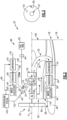
- FIGS 1 and 2 schematically illustrate an example steam injected and intercooled aircraft propulsion system that is generally indicated at 20.
- Heat exchangers utilized to recover water and generate steam operate most effectively with low pressure drops provided by large flow facing areas.
- the example propulsion system 20 incorporates heat exchangers for evaporator and condenser systems within a nacelle 48 to enable larger flow facing areas.
- a gas generating core engine 24 is inclined relative to a fan axis A to free additional space within the nacelle 48 for ducting of gas flows and cooling flows to heat exchangers of a water recovery system 25 and an evaporator assembly 54.
- the propulsion system 20 includes a gas generating core engine 24 supported along a core engine axis 34 that is offset at an angle 46 relative to a fan axis A.
- the example angle 46 is between around 25° and 45° however other angles could be utilized and are within the contemplation and scope of this disclosure.
- the relatively small size of the core engine 24 is enabled by the additional engine efficiency and power provided by steam injection.
- the small size of the core engine 24 enables the offset inclined orientation that provides additional space within the nacelle 48 for heat exchangers associated with water recovery and steam generation systems.
- example propulsion system 20 is shown and described by way of example as including a fan disposed within a nacelle 48, other engine architectures, such as for example an open rotor engine configuration is within the contemplation and scope of this disclosure.
- an inlet airflow 62 is communicated into the core engine 24 through the propulsive fan 22.
- the fan 22 includes a plurality of fan blades 65 supported on a center fan hub 67. In one disclosed example, the fan 22 is disposed at least partially within the nacelle 48. Accordingly, the inlet airflow 62 is communicated through an annular area 63 between the fan hub 67 and an inner surface 85 of the nacelle 48.
- the core engine 24 includes a compressor section 26 that communicates compressed inlet airflow 62 to a combustor section 28 where it is mixed with fuel and ignited to generate a core gas flow 36. The gas flow 36 generated by the core engine 24 expands through a turbine section 30 to produce shaft power to drive the compressor section 26.
- the core engine 24 may be configured to burn hydrogen provided by a fuel system 98.
- the example fuel system 98 includes a liquid hydrogen (LH 2 ) tank 92 in communication with at least one pump 94.
- the pump 94 drives a fuel flow 96 to the core engine 24.
- hydrogen is shown and described by way of example, other non-carbon based fuels, biofuels or other sustainable aircraft fuels could also be utilized and are within the scope and contemplation of this disclosure. Additionally, traditional carbon-based fuels could also be utilized and are within the contemplation and scope of this disclosure.
- a steam flow 56 is injected into the core engine 24 to provide an increased power output.
- the injected steam flow 56 provides increased power by increasing mass flow through the turbine section 30 without a corresponding increase in work from the compressor section 26.
- An example engine operation cycle may include up to (or more than) 35% steam-air-ratios (SAR) and may be assisted by a multiple fold (e.g., 2x, 3x, etc.) increase in moisture from burning H 2 as the fuel.
- SAR steam-air-ratios
- An intercooling system 100 ( Figure 2 ) provides an intercooling water flow 102 that is communicated to the core engine 24 to reduce a temperature of the core flows and increase mass flow. Water flow 102 injected into the compressor section 26 reduces temperatures of a core compressed inlet flow to provide an increased mass flow that decreases the work required by the compressor section 26.
- the core gas flow 36 exhausted from the core engine 24 is routed through a transition duct 74 to a power turbine 32.
- the expansion of the gas flow 36 through the power turbine 32 drives the fan 22 through a driveshaft 44 and gearbox 42.
- an example core engine 24 and power turbine 32 are disclosed by way of example, other turbine engine architectures could be utilized and are within the scope and contemplation of this disclosure.
- the gas flow 36 exhausted from the power turbine 32 is routed through a turbine exhaust case 50 into an exhaust duct assembly 52.
- the exhaust duct assembly 52 directs the gas flow 36 radially outward toward an evaporator assembly 54 and the water recovery system 25.
- the example water recovery system 25 includes a condenser 58 and a water collector 64.
- the gas flow 36 sequentially proceeds through the evaporator assembly 54, the condenser 58 and the water collector 64. From the water collector 64, gas flow 70 is exhausted into a fan flow duct 68 or into the ambient environment.
- the example condenser 58 and evaporator 54 are heat exchangers that provide thermal communication between different flows.
- the condenser 58 provides for thermal communication between a cooling flow 40 and the gas flow 36 to cool the gas flow and condense water into a liquid form.
- the evaporator 54 provides thermal communication between the water flow 66 and the gas flow 36 to heat the water flow and generate steam subsequently injected into the core engine 24.
- the example nacelle 48 includes a fan case 82 surrounding the fan 22 and defining a portion of the inner surface 85.
- An internal space 87 within the nacelle 48 is defined between an outer surface 83 and the inner surface 85 along a length of the nacelle 48. Portions of the condenser 58, the water collector 64, the evaporator assembly and an ejector duct 60 are disposed with the internal space 87. Mounting at the inner surface 85 and within the internal space 87 of the nacelle 48 provides large areas for location of the condenser 58 and evaporator 54.
- a fan flow duct 68 extends from the fan 22 along the fan axis A to an exit plane 76.
- the fan flow duct 68 defines a bypass flow path B for a propulsive bypass flow 38.
- a portion of the inlet flow 62 is communicated to the core engine 24 and utilized for generation of the gas flow 36.
- the bypass flow 38 flows around the core engine 24 and the power turbine 32 and passes through a fan duct opening 80 disposed at the exit plane 76 of the nacelle 48.
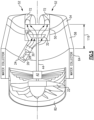
- a portion of the inlet flow 62 is communicated into an inlet 118 of the ejector duct 60 to provide the cooling flow 40 to the condenser 58.
- the cooling flow 40 through ejector duct 60 is placed in thermal communication with the gas flow 36 in the condenser 58.
- the cooling flow 40 is then exhausted through an ejector exit opening 78 disposed within the exit plane 76.
- the ejector exit opening 78 is disposed radially outward of the fan flow duct opening 80.
- the area of the ejector inlet 118 is determined relative to the inlet area 63 through the fan 22 defined between the hub 67 and the inner surface 85 of the nacelle 48. In one example embodiment, the area of the ejector inlet 118 is between 4% and 30% of the inlet area 63 through the fan 22. In another example embodiment, the area of the ejector inlet 118 is between 10% and 20% of the inlet area 63. In another example embodiment, the area of the ejector inlet is between 15% and 20% of the inlet area 63.
- the exhaust duct assembly 52 includes a plurality of radial parts 72 that extend radially outward from the turbine exhaust case 50 toward the inner surface 85 of the nacelle 48.
- four radial parts 72 are provided that direct gas flow 36 toward accumulator portions 84.
- the four radial parts 72 are spaced apart circumferentially and communicate the gas flow 36 to accumulator portions 84.
- two accumulator portions 84 are disposed on opposite sides of the fan axis A and each are fed gas flow 36 by two of the four radial parts 72. The accumulator portions 84 communicate the gas flow 36 to the evaporator assembly 54 than to the condenser 58.
- the example condenser 58 comprises a first condenser portion 86 and a second condenser portion 88.
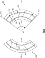
- Figure 6 is a schematic view of a portion of the first and second condenser portions 86, 88 through a section transverse to the fan axis A.
- the condenser portions 86, 88 are generally configured as ring sectors.
- a ring sector is a portion of a circle bounded by arcs of differing radii bounded by radial lines separated by a central angle 90.
- the condenser portions 86, 88 include an arc shaped inner surface 108 radially spaced apart from an arc shaped outer surface 110.
- the inner surface 108 and the outer surface 110 extend between radial lines 112 and 114 that are separated by the central angle 90.
- the central angle 90 is between 60 degrees and 120 degrees. In another example embodiment, the central angle 90 is between 70 degrees and 110 degrees.
- the example condenser portions 86, 88 are generally shaped as a sector of an annulus, but may be shaped in irregular shapes that correspond with structural features of the nacelle 48.
- the example disclosed shape provides a large flow facing area for the cooling flow 40 from the ejector duct 60.
- a first ejector duct 60A is provided with the first condenser portion 86 and a second ejector duct 60B is provided with the second condenser portion 88.
- Each of the ejector ducts 60A, 60B include an inner portion 104 that feeds the cooling flow 40 to the condenser 58 and an outer portion 106 that receives cooling airflow exhausted from the condenser portions 86, 88. Accordingly, the cooling flow 40 flows radially outward from the inner portion 104, through the corresponding condenser portions 86, 88 to the outer portion 106.
- each of the condenser portions 86, 88 provides an inlet face area for the cooling flow 40.
- the inlet flow area includes the surface 108 along an axial length 116 ( Figure 4 ) of the of the condenser portions 86, 88.
- the large face area provides for the advantageous application of cooling flow 40 to each of the condenser portions 86, 88 within the nacelle 48.
- each of the ejector ducts 60A, 60B provide an increasing flow area between an inlet 118 for the cooling flow and an outlet 120 to the condenser 58.
- the increasing area provides beneficial cooling flow characteristics that improve thermal communication with the exhaust gas flow 36 through the condenser 58.
- the difference in flow areas between the inlet 118 and the outlet 120 at the condenser 58 can be described as a ratio between the area at the outlet 120 relative to the area at the inlet 118.
- a ratio of the area at the outlet 120 to the area at the inlet 118 is between 4 and 20.
- a ratio of the area of the outlet 120 to the area of the inlet 118 is between 10 and 20.
- the ratio of the area of the outlet 120 to the area of the inlet 118 is between 12 and 18.
- the annular configuration and shape of the condenser portions 86, 88 provide large flow facing areas at the inlet surface 108 for receiving the cooling flow 40.
- the large flow facing areas are enabled by locating the condenser portions 86, 88 in the nacelle 48.
- the outer portion 106 of the ejector ducts 60A, 60B, include an outlet 122 with a flow area larger than a flow area at the ejector exit opening 78.
- the example propulsion system embodiments include an evaporator and condenser with increased efficiencies by providing corresponding heat exchangers within the nacelle assembly such that larger surface areas can be realized for thermal transfer between cooling and heating flows.
- the inclined mounting of the gas generating core engine provides additional space within the nacelle assembly for larger heat exchangers while maintaining compatibility with traditional engine mounting locations.
Landscapes
- Engineering & Computer Science (AREA)
- Chemical & Material Sciences (AREA)
- Combustion & Propulsion (AREA)
- Mechanical Engineering (AREA)
- General Engineering & Computer Science (AREA)
- Structures Of Non-Positive Displacement Pumps (AREA)
Abstract
Description
- The present disclosure relates generally to an aircraft propulsion system and, more particularly, to a turbine engine including an offset gas generating core engine and nacelle mounted heat exchangers.
- Reduction and/or elimination of carbon emissions generated by aircraft operation is a stated goal of aircraft manufacturers and airline operators. Gas turbine engines compress incoming core airflow, mix the compressed airflow with fuel that is ignited in a combustor to generate an exhaust gas flow. Some energy in the exhaust flow is recovered as it is expanded through a turbine section, however, much of the heat energy within the exhaust gas flow is lost. Some heat energy may be recaptured and used to generate a steam flow that is injected into the core flow. The steam flow increases engine efficiencies by increasing mass flow without additional work required by the compressor section. Efficient heat exchangers for capturing heat and generating steam have large flow facing areas and are large compared to the overall engine size.
- A propulsion system for an aircraft according to aspect of the present invention includes, among other possible things, a fan that is rotatable about a fan axis, a core engine that is configured for generating a gas flow utilized to generate shaft power for driving the fan, a nacelle that surrounds the core engine and the fan, a condenser where water in the gas flow is condensed into a liquid form, an exhaust duct assembly where the gas flow exhausted from the core engine is directed to the condenser, an ejector duct where a portion of a bypass airflow is thermally communicated with the condenser to cool the gas flow, and an evaporator assembly that is in thermal communication with the exhaust duct where water recovered by the condenser is heated to generate a steam flow that is subsequently communicated to the core engine.
- Optionally, and in accordance with the above, the core engine is disposed about a core engine axis that is offset relative to the fan axis.
- Optionally, and in accordance with any of the above, the propulsion system includes a power turbine that is coupled to the fan through a driveshaft. The gas flow from the core engine is received and expanded through the power turbine to drive the drive shaft.
- Optionally, and in accordance with any of the above, the condenser includes a first condenser portion and a second condenser portion that is separate from the first condenser portion.
- Optionally, and in accordance with any of the above, a cross-section transverse to the fan axis through either or both of the first condenser portion and the second condenser portion defines a ring sector area.
- Optionally, and in accordance with any of the above, a central angle of the ring sector area for either or both of the first condenser portion and the second condenser portion is between 60 degrees and 120 degrees.
- Optionally, and in accordance with any of the above, the propulsion system further includes an exhaust case where gas flow from the power turbine is communicated to the exhaust duct assembly. The exhaust duct assembly extends radially outward from the exhaust case toward the nacelle.
- Optionally, and in accordance with any of the above, the exhaust duct assembly includes a plurality of radial duct parts that extend radially outward from the exhaust case toward the nacelle.
- Optionally, and in accordance with any of the above, the evaporator assembly is in thermal communication with at least a portion of the exhaust duct assembly between the exhaust case and the condenser.
- Optionally, and in accordance with any of the above, the ejector duct includes an ejector exit opening separate from a fan flow duct opening and radially outward of the fan flow duct opening.
- Optionally, and in accordance with any of the above, the ejector duct includes a flow area that increases from an area at an ejector inlet to an area at an outlet to the condenser.
- Optionally, and in accordance with any of the above, the flow area of the ejector duct includes a ratio between a flow area at the outlet to the condenser relative to a flow area at the ejector inlet that is between 4 and 20.
- Optionally, and in accordance with any of the above, a flow area of the ejector inlet is between 4% and 30% of a flow area through the fan.
- A propulsion system for an aircraft according to another aspect of the present invention includes, among other possible things, a fan that is rotatable about a fan axis, a core engine that is configured for generating a gas flow, the core engine is disposed about a core engine axis that is inclined relative to the fan axis, a power turbine where the gas flow from the core engine is expanded to generate shaft power that is utilized to drive the fan, a nacelle that surrounds the core engine and the fan, a fan flow duct that defines a bypass flow path around the core engine and the power turbine through the nacelle, a water recovery system that includes a condenser where water in the gas flow is condensed into a liquid and a water collector where the condensed water is separated from the gas flow, an exhaust duct assembly where the gas flow exhausted from the core engine is directed to the condenser, an ejector duct where a portion of a bypass airflow is thermally communicated with the condenser, and an evaporator assembly that is in thermal communication with the exhaust duct where water recovered from the water collector is heated to generate a steam flow that is communicated to the core engine.
- Optionally, and in accordance with any of the above, the propulsion system includes an exhaust case where gas flow exhausted from the power turbine is communicated to the exhaust duct assembly,
- Optionally, and in accordance with any of the above, the exhaust duct assembly includes a plurality of radial duct parts that extend radially outward from the exhaust case toward the nacelle.
- Optionally, and in accordance with any of the above, the condenser includes a first condenser portion and a second condenser portion and the plurality of radial duct parts are circumferentially spaced apart and divided to communicate gas flow to a corresponding one of the first condenser portion and the second condenser portion.
- Optionally, and in accordance with any of the above, the ejector duct includes an exit opening that is radially outward of a fan flow duct opening, and each of the fan flow duct opening and the ejector exit opening are disposed within a common exit plan transverse to the fan axis.
- A method of operating a gas turbine engine, the method, according to another aspect of the present invention includes, among other possible things, generating a gas flow with a core engine that is disposed about a core engine axis that is inclined relative to a fan axis, generating shaft power to drive the fan with a power turbine that receives the gas flow from the core engine, bypassing an airflow that is generated by the fan around the core engine and the power turbine through a fan flow duct that is defined within a nacelle, directing the gas flow to a condenser through an exhaust duct assembly, cooling the gas flow in the condenser with a portion of the airflow generated by the fan and directed through an ejector duct that is in thermal communication with the condenser, generating a steam flow by heating water that is recovered by the condenser in an evaporator assembly that is in thermal communication with the gas flow, and injecting at least a portion of the generated steam flow into the core engine.
- Optionally, and in accordance with any of the above, the condenser includes a first condenser portion and a second condenser portion that is disposed on opposite sides of the fan flow duct and the method further includes directing a first part of the airflow that is generated by the fan into thermal communication with the first condenser portion and the second condenser portion through the ejector duct that is separate from airflow through the fan flow duct.
- Although the different examples have the specific components shown in the illustrations, embodiments of this invention are not limited to those particular combinations. It is possible to use some of the components or features from one of the examples in combination with features or components from another one of the examples.
- These and other features disclosed herein can be best understood from the following specification and drawings, the following of which is a brief description.
-
-
Figure 1 is a cross-sectional view of an example aircraft propulsion system. -
Figure 2 is a schematic view of the example aircraft propulsion system. -
Figure 3 is a schematic view of an inlet area of the example aircraft propulsion system embodiment. -
Figure 4 is an aft view of the example exhaust duct assembly. -
Figure 5 is a sectional view of portions of an exhaust duct assembly and a water recovery system. -
Figure 6 is a schematic view of an example condenser embodiment through a section transverse to an engine fan axis. -
Figure 7 is a schematic view of an example ejector duct and the condenser. -
Figures 1 and2 schematically illustrate an example steam injected and intercooled aircraft propulsion system that is generally indicated at 20. Heat exchangers utilized to recover water and generate steam operate most effectively with low pressure drops provided by large flow facing areas. Theexample propulsion system 20 incorporates heat exchangers for evaporator and condenser systems within anacelle 48 to enable larger flow facing areas. Moreover, a gas generatingcore engine 24 is inclined relative to a fan axis A to free additional space within thenacelle 48 for ducting of gas flows and cooling flows to heat exchangers of awater recovery system 25 and anevaporator assembly 54. - The
propulsion system 20 includes a gas generatingcore engine 24 supported along acore engine axis 34 that is offset at anangle 46 relative to a fan axis A. Theexample angle 46 is between around 25° and 45° however other angles could be utilized and are within the contemplation and scope of this disclosure. The relatively small size of thecore engine 24 is enabled by the additional engine efficiency and power provided by steam injection. The small size of thecore engine 24 enables the offset inclined orientation that provides additional space within thenacelle 48 for heat exchangers associated with water recovery and steam generation systems. - Although the
example propulsion system 20 is shown and described by way of example as including a fan disposed within anacelle 48, other engine architectures, such as for example an open rotor engine configuration is within the contemplation and scope of this disclosure. - Referring to
Figure 3 , with continued reference toFigures 1 and2 , aninlet airflow 62 is communicated into thecore engine 24 through thepropulsive fan 22. Thefan 22 includes a plurality offan blades 65 supported on acenter fan hub 67. In one disclosed example, thefan 22 is disposed at least partially within thenacelle 48. Accordingly, theinlet airflow 62 is communicated through anannular area 63 between thefan hub 67 and aninner surface 85 of thenacelle 48. Thecore engine 24 includes acompressor section 26 that communicates compressedinlet airflow 62 to acombustor section 28 where it is mixed with fuel and ignited to generate acore gas flow 36. Thegas flow 36 generated by thecore engine 24 expands through aturbine section 30 to produce shaft power to drive thecompressor section 26. - The
core engine 24 may be configured to burn hydrogen provided by afuel system 98. (Figure 2 ) Theexample fuel system 98 includes a liquid hydrogen (LH2)tank 92 in communication with at least onepump 94. Thepump 94 drives afuel flow 96 to thecore engine 24. Although hydrogen is shown and described by way of example, other non-carbon based fuels, biofuels or other sustainable aircraft fuels could also be utilized and are within the scope and contemplation of this disclosure. Additionally, traditional carbon-based fuels could also be utilized and are within the contemplation and scope of this disclosure. - A
steam flow 56 is injected into thecore engine 24 to provide an increased power output. The injectedsteam flow 56 provides increased power by increasing mass flow through theturbine section 30 without a corresponding increase in work from thecompressor section 26. An example engine operation cycle may include up to (or more than) 35% steam-air-ratios (SAR) and may be assisted by a multiple fold (e.g., 2x, 3x, etc.) increase in moisture from burning H2 as the fuel. - An intercooling system 100 (
Figure 2 ) provides anintercooling water flow 102 that is communicated to thecore engine 24 to reduce a temperature of the core flows and increase mass flow.Water flow 102 injected into thecompressor section 26 reduces temperatures of a core compressed inlet flow to provide an increased mass flow that decreases the work required by thecompressor section 26. - The
core gas flow 36 exhausted from thecore engine 24 is routed through atransition duct 74 to apower turbine 32. The expansion of thegas flow 36 through thepower turbine 32 drives thefan 22 through adriveshaft 44 andgearbox 42. Although anexample core engine 24 andpower turbine 32 are disclosed by way of example, other turbine engine architectures could be utilized and are within the scope and contemplation of this disclosure. - The
gas flow 36 exhausted from thepower turbine 32 is routed through aturbine exhaust case 50 into anexhaust duct assembly 52. Theexhaust duct assembly 52 directs thegas flow 36 radially outward toward anevaporator assembly 54 and thewater recovery system 25. The examplewater recovery system 25 includes acondenser 58 and awater collector 64. Thegas flow 36 sequentially proceeds through theevaporator assembly 54, thecondenser 58 and thewater collector 64. From thewater collector 64,gas flow 70 is exhausted into afan flow duct 68 or into the ambient environment. - The
example condenser 58 andevaporator 54 are heat exchangers that provide thermal communication between different flows. Thecondenser 58 provides for thermal communication between a coolingflow 40 and thegas flow 36 to cool the gas flow and condense water into a liquid form. Theevaporator 54 provides thermal communication between thewater flow 66 and thegas flow 36 to heat the water flow and generate steam subsequently injected into thecore engine 24. - The
example nacelle 48 includes afan case 82 surrounding thefan 22 and defining a portion of theinner surface 85. Aninternal space 87 within thenacelle 48 is defined between anouter surface 83 and theinner surface 85 along a length of thenacelle 48. Portions of thecondenser 58, thewater collector 64, the evaporator assembly and anejector duct 60 are disposed with theinternal space 87. Mounting at theinner surface 85 and within theinternal space 87 of thenacelle 48 provides large areas for location of thecondenser 58 andevaporator 54. - A
fan flow duct 68 extends from thefan 22 along the fan axis A to anexit plane 76. Thefan flow duct 68 defines a bypass flow path B for apropulsive bypass flow 38. A portion of theinlet flow 62 is communicated to thecore engine 24 and utilized for generation of thegas flow 36. Thebypass flow 38 flows around thecore engine 24 and thepower turbine 32 and passes through afan duct opening 80 disposed at theexit plane 76 of thenacelle 48. - A portion of the
inlet flow 62 is communicated into aninlet 118 of theejector duct 60 to provide thecooling flow 40 to thecondenser 58. The coolingflow 40 throughejector duct 60 is placed in thermal communication with thegas flow 36 in thecondenser 58. The coolingflow 40 is then exhausted through an ejector exit opening 78 disposed within theexit plane 76. In one example embodiment, theejector exit opening 78 is disposed radially outward of the fanflow duct opening 80. - The area of the
ejector inlet 118 is determined relative to theinlet area 63 through thefan 22 defined between thehub 67 and theinner surface 85 of thenacelle 48. In one example embodiment, the area of theejector inlet 118 is between 4% and 30% of theinlet area 63 through thefan 22. In another example embodiment, the area of theejector inlet 118 is between 10% and 20% of theinlet area 63. In another example embodiment, the area of the ejector inlet is between 15% and 20% of theinlet area 63. - Referring to
Figures 4 and5 with continued reference toFigures 1 and2 , theexhaust duct assembly 52 includes a plurality ofradial parts 72 that extend radially outward from theturbine exhaust case 50 toward theinner surface 85 of thenacelle 48. In one disclosed example, fourradial parts 72 are provided thatdirect gas flow 36 towardaccumulator portions 84. In one disclosed example, the fourradial parts 72 are spaced apart circumferentially and communicate thegas flow 36 toaccumulator portions 84. In one disclosed example, twoaccumulator portions 84 are disposed on opposite sides of the fan axis A and each are fedgas flow 36 by two of the fourradial parts 72. Theaccumulator portions 84 communicate thegas flow 36 to theevaporator assembly 54 than to thecondenser 58. - Referring to
Figure 6 with continued reference toFigure 5 , theexample condenser 58 comprises afirst condenser portion 86 and asecond condenser portion 88.Figure 6 is a schematic view of a portion of the first andsecond condenser portions - The
condenser portions central angle 90. In one disclosed example, thecondenser portions inner surface 108 radially spaced apart from an arc shapedouter surface 110. Theinner surface 108 and theouter surface 110 extend betweenradial lines central angle 90. In one disclosed example, thecentral angle 90 is between 60 degrees and 120 degrees. In another example embodiment, thecentral angle 90 is between 70 degrees and 110 degrees. Theexample condenser portions nacelle 48. The example disclosed shape provides a large flow facing area for thecooling flow 40 from theejector duct 60. - In the example shown schematically in
Figure 6 , afirst ejector duct 60A is provided with thefirst condenser portion 86 and asecond ejector duct 60B is provided with thesecond condenser portion 88. Each of theejector ducts inner portion 104 that feeds the coolingflow 40 to thecondenser 58 and anouter portion 106 that receives cooling airflow exhausted from thecondenser portions flow 40 flows radially outward from theinner portion 104, through the correspondingcondenser portions outer portion 106. Theinner surface 108 of each of thecondenser portions cooling flow 40. The inlet flow area includes thesurface 108 along an axial length 116 (Figure 4 ) of the of thecondenser portions cooling flow 40 to each of thecondenser portions nacelle 48. - Referring to
Figure 7 , with continued reference toFigures 5 and6 , theinner portion 104 of each of theejector ducts inlet 118 for the cooling flow and anoutlet 120 to thecondenser 58. The increasing area provides beneficial cooling flow characteristics that improve thermal communication with theexhaust gas flow 36 through thecondenser 58. The difference in flow areas between theinlet 118 and theoutlet 120 at thecondenser 58 can be described as a ratio between the area at theoutlet 120 relative to the area at theinlet 118. In one example disclosed embodiment, a ratio of the area at theoutlet 120 to the area at theinlet 118 is between 4 and 20. In another disclosed embodiment, a ratio of the area of theoutlet 120 to the area of theinlet 118 is between 10 and 20. In another disclosed example embodiment, the ratio of the area of theoutlet 120 to the area of theinlet 118 is between 12 and 18. - The annular configuration and shape of the
condenser portions inlet surface 108 for receiving the coolingflow 40. The large flow facing areas are enabled by locating thecondenser portions nacelle 48. Theouter portion 106 of theejector ducts outlet 122 with a flow area larger than a flow area at theejector exit opening 78. - Although an example engine configuration is described by way of example, it will be appreciated that other engine configurations may include additional structures and features and are within the contemplation and scope of this disclosure.
- Accordingly, the example propulsion system embodiments include an evaporator and condenser with increased efficiencies by providing corresponding heat exchangers within the nacelle assembly such that larger surface areas can be realized for thermal transfer between cooling and heating flows. Moreover, the inclined mounting of the gas generating core engine provides additional space within the nacelle assembly for larger heat exchangers while maintaining compatibility with traditional engine mounting locations.
- Although an example embodiment has been disclosed, a worker of ordinary skill in this art would recognize that certain modifications would come within the scope of this disclosure. For that reason, the following claims should be studied to determine the scope and content of this disclosure.
Claims (15)
- A propulsion system (20) for an aircraft, the propulsion system comprising:a fan (22) rotatable about a fan axis (A);a core engine (24) configured for generating a gas flow (36) that is utilized to generate shaft power for driving the fan (22);a nacelle (48) surrounding the core engine (24);a condenser (58) configured to condense water in the gas flow (36) into a liquid form;an exhaust duct assembly (52) configured to direct the gas flow (36) exhausted from the core engine (24) to the condenser (58);an ejector duct (60) configured to thermally contact a portion (40) of a bypass airflow (38) with the condenser (58) to cool the gas flow (36); andan evaporator assembly (54) in thermal contact with the exhaust duct assembly (52) and configured to heat water from the condenser (58) to generate a steam flow (56) that is communicated to the core engine (24).
- The propulsion system (20) as recited in claim 1, wherein the core engine (24) is disposed about a core engine axis (34) that is offset at an angle (46) relative to the fan axis (A).
- The propulsion system (20) as recited in claim 1 or 2, including a power turbine (32) coupled to the fan (22) through a driveshaft (44), wherein the power turbine (32) is configured to receive and expand the gas flow (36) from the core engine (24) to drive the drive shaft (44).
- The propulsion system (20) as recited in claim 1, 2 or 3, wherein the condenser (58) comprises a first condenser portion (86) and a second condenser portion (88) separate from the first condenser portion (86).
- The propulsion system (20) as recited in claim 4, wherein a cross-section transverse to the fan axis (A) through either or both of the first condenser portion (86) and the second condenser portion (88) defines a ring sector area, optionally wherein:
a central angle (90) of the ring sector area for either or both of the first condenser portion (86) and the second condenser portion (88) is between 60 degrees and 120 degrees. - The propulsion system (20) as recited in claim 3, or claim 4 or 5 when dependent on claim 3, further comprising an exhaust case (50) configured to communicate gas flow (36) exhausted from the power turbine (32) to the exhaust duct assembly (52), wherein the exhaust duct assembly (52) extends radially outward from the exhaust case (50) toward the nacelle (48).
- The propulsion system (20) as recited in claim 6, wherein the exhaust duct assembly (52) comprises a plurality of radial duct parts (72) that extend radially outward from the exhaust case (50) toward the nacelle (48).
- The propulsion system (20) as recited in claim 6 or 7, wherein the evaporator assembly (54) is in thermal communication with at least a portion of the exhaust duct assembly (52) between the exhaust case (50) and the condenser (58).
- The propulsion system (20) as recited in any preceding claim, wherein the ejector duct (60) includes an ejector exit opening (78) separate from a fan flow duct opening (80) and radially outward of the fan flow duct opening (80).
- The propulsion system (20) as recited in any preceding claim, wherein the ejector duct comprises (60) a flow area that increases from an area at an ejector inlet (118) to an area at an outlet (120) to the condenser (58), optionally wherein:
the flow area of the ejector duct (60) includes a ratio between a flow area at the outlet (120) to the condenser (58) relative to a flow area at the ejector inlet (118) that is between 4 and 20, further optionally wherein:
a flow area of the ejector inlet (118) is between 4% and 30% of a flow area (63) through the fan (22). - A propulsion system (20) for an aircraft, the propulsion system comprising:a fan (22) rotatable about a fan axis (A);a core engine (24) configured for generating a gas flow (36), the core engine (24) is disposed about a core engine axis (34) that is inclined relative to the fan axis (A);a power turbine (32) configured to expand the gas flow (36) from the core engine (24) to generate shaft power utilized to drive the fan (22);a nacelle (48) surrounding the core engine (24) and the fan (22);a fan flow duct (68) defining a bypass flow path (B) around the core engine (24) and the power turbine (32) through the nacelle (48);a water recovery system (25) including a condenser (58) configured to condense water in the gas flow (36) into a liquid and a water collector (64) configured to separate the condensed water from the gas flow (36);an exhaust duct assembly (52) configured to direct the gas flow (36) exhausted from the core engine (24) to the condenser (58);an ejector duct (60) configured to thermally contact a portion (40) of a bypass airflow (38) with the condenser (58); andan evaporator assembly (54) in thermal contact with the exhaust duct assembly (52), wherein the evaporator assembly (54) is configured to heat water recovered from the water collector (64) to generate a steam flow (56) that is communicated to the core engine (24).
- The propulsion system (20) as recited in claim 11, including an exhaust case (50) configured to communicate gas flow (36) exhausted from the power turbine (32) to the exhaust duct assembly (52).
- The propulsion system (20) as recited in claim 12, wherein the exhaust duct assembly (52) comprises a plurality of radial duct parts (72) that extend radially outward from the exhaust case (50) toward the nacelle (48), optionally wherein:
the condenser (58) comprises a first condenser portion (86) and a second condenser portion (88) and the plurality of radial duct parts (72) are circumferentially spaced apart and divided to communicate the gas flow (36) to a corresponding one of the first condenser portion (86) and the second condenser portion (88). - The propulsion system (20) as recited in any of claims 11 to 13, wherein the ejector duct (60) includes an exit opening (78) that is radially outward of a fan flow duct opening (80), and each of the fan flow duct opening (80) and the ejector exit opening (78) are disposed within a common exit plane (76) transverse to the fan axis (A).
- A method of operating a gas turbine engine, the method comprising:generating a gas flow (36) using a core engine (24) that is disposed about a core engine axis (34) that is inclined relative to a fan axis (A);generating shaft power to drive a fan (22) using a power turbine (32) receiving the gas flow (36) from the core engine (24);bypassing an airflow generated by the fan (22) around the core engine (24) and the power turbine (32) through a fan flow duct (68) defined within a nacelle (48);directing the gas flow (36) to a condenser (58) through an exhaust duct assembly (52);cooling the gas flow (36) in the condenser (58) using a portion (40) of the airflow generated by the fan (22) and directed through an ejector duct (60) in thermal contact with the condenser (58);generating a steam flow (56) by heating water recovered by the condenser (58) in an evaporator assembly (54) in thermal communication with the gas flow (36); and injecting at least a portion of the generated steam flow (56) into the core engine (24), optionally wherein:
the condenser (58) comprises a first condenser portion (86) and a second condenser portion (88) disposed on opposite sides of the fan flow duct (68) and the method further comprises directing a first part of the airflow generated by the fan (22) into thermal communication with the first condenser portion (86) and the second condenser portion (88) through the ejector duct (60) separate from airflow through the fan flow duct (68).
Priority Applications (1)
| Application Number | Priority Date | Filing Date | Title |
|---|---|---|---|
| EP26160463.1A EP4722516A2 (en) | 2023-04-28 | 2024-04-29 | Offset core with side ejector nacelle nozzles |
Applications Claiming Priority (1)
| Application Number | Priority Date | Filing Date | Title |
|---|---|---|---|
| US18/309,023 US12577904B2 (en) | 2023-04-28 | 2023-04-28 | Offset core with side ejector nacelle nozzles |
Related Child Applications (1)
| Application Number | Title | Priority Date | Filing Date |
|---|---|---|---|
| EP26160463.1A Division EP4722516A2 (en) | 2023-04-28 | 2024-04-29 | Offset core with side ejector nacelle nozzles |
Publications (2)
| Publication Number | Publication Date |
|---|---|
| EP4455465A1 true EP4455465A1 (en) | 2024-10-30 |
| EP4455465B1 EP4455465B1 (en) | 2026-02-25 |
Family
ID=90924117
Family Applications (2)
| Application Number | Title | Priority Date | Filing Date |
|---|---|---|---|
| EP26160463.1A Pending EP4722516A2 (en) | 2023-04-28 | 2024-04-29 | Offset core with side ejector nacelle nozzles |
| EP24173188.4A Active EP4455465B1 (en) | 2023-04-28 | 2024-04-29 | Offset core with side ejector nacelle nozzles |
Family Applications Before (1)
| Application Number | Title | Priority Date | Filing Date |
|---|---|---|---|
| EP26160463.1A Pending EP4722516A2 (en) | 2023-04-28 | 2024-04-29 | Offset core with side ejector nacelle nozzles |
Country Status (2)
| Country | Link |
|---|---|
| US (1) | US12577904B2 (en) |
| EP (2) | EP4722516A2 (en) |
Cited By (1)
| Publication number | Priority date | Publication date | Assignee | Title |
|---|---|---|---|---|
| EP4675092A1 (en) * | 2024-07-01 | 2026-01-07 | RTX Corporation | Fan case mounted evaporator for aircraft turbine engine |
Families Citing this family (1)
| Publication number | Priority date | Publication date | Assignee | Title |
|---|---|---|---|---|
| US20250369393A1 (en) * | 2024-05-30 | 2025-12-04 | Rtx Corporation | Axial flow angled condenser arrangement for an aircraft propulsion system |
Citations (3)
| Publication number | Priority date | Publication date | Assignee | Title |
|---|---|---|---|---|
| US2447696A (en) * | 1944-12-13 | 1948-08-24 | Fairey Aviat Co Ltd | Combustion gas and steam turbine arrangement |
| DE102019203595A1 (en) * | 2019-03-15 | 2020-09-17 | MTU Aero Engines AG | Aircraft |
| US11603798B1 (en) * | 2022-02-11 | 2023-03-14 | Raytheon Technologies Corporation | Cryogenically assisted exhaust condensation |
Family Cites Families (5)
| Publication number | Priority date | Publication date | Assignee | Title |
|---|---|---|---|---|
| US5896740A (en) * | 1996-09-12 | 1999-04-27 | Shouman; Ahmad R. | Dual cycle turbine engine having increased efficiency and heat recovery system for use therein |
| JP2001027131A (en) * | 1999-07-16 | 2001-01-30 | Ishikawajima Harima Heavy Ind Co Ltd | Double-pressure steam injection partial regeneration cycle gas turbine |
| CA2497576A1 (en) * | 2002-07-14 | 2004-01-29 | Wolfgang Harazim | Method for the separation of residual gases and working fluid in a combined cycle water/steam process |
| US10024235B2 (en) | 2014-03-03 | 2018-07-17 | United Technologies Corporation | Offset core engine architecture |
| US20200109667A1 (en) * | 2018-10-04 | 2020-04-09 | United Technologies Corporation | Jet engine heat exchanger system |
-
2023
- 2023-04-28 US US18/309,023 patent/US12577904B2/en active Active
-
2024
- 2024-04-29 EP EP26160463.1A patent/EP4722516A2/en active Pending
- 2024-04-29 EP EP24173188.4A patent/EP4455465B1/en active Active
Patent Citations (3)
| Publication number | Priority date | Publication date | Assignee | Title |
|---|---|---|---|---|
| US2447696A (en) * | 1944-12-13 | 1948-08-24 | Fairey Aviat Co Ltd | Combustion gas and steam turbine arrangement |
| DE102019203595A1 (en) * | 2019-03-15 | 2020-09-17 | MTU Aero Engines AG | Aircraft |
| US11603798B1 (en) * | 2022-02-11 | 2023-03-14 | Raytheon Technologies Corporation | Cryogenically assisted exhaust condensation |
Cited By (1)
| Publication number | Priority date | Publication date | Assignee | Title |
|---|---|---|---|---|
| EP4675092A1 (en) * | 2024-07-01 | 2026-01-07 | RTX Corporation | Fan case mounted evaporator for aircraft turbine engine |
Also Published As
| Publication number | Publication date |
|---|---|
| US20240360784A1 (en) | 2024-10-31 |
| EP4722516A2 (en) | 2026-04-08 |
| US12577904B2 (en) | 2026-03-17 |
| EP4455465B1 (en) | 2026-02-25 |
Similar Documents
| Publication | Publication Date | Title |
|---|---|---|
| EP4279722B1 (en) | WATER SEPARATOR FOR HYDROGEN-DRIVED TURBINE ENGINE | |
| EP4455465B1 (en) | Offset core with side ejector nacelle nozzles | |
| US12163467B2 (en) | Condenser for hydrogen steam injected turbine engine | |
| US12092022B2 (en) | Forward mounted hydrogen steam injected and inter-cooled turbine engine with octopus ducting | |
| EP4279718B1 (en) | Hydrogen fueled turbine engine condenser duct | |
| US11920515B2 (en) | Condenser for hydrogen steam injected turbine engine | |
| JP7608139B2 (en) | Systems and methods for operating a turbocharged gas turbine engine - Patents.com | |
| EP4656858A2 (en) | Circumferential flow condenser arrangement for an aircraft propulsion system | |
| EP4279721B1 (en) | Reverse flow hydrogen steam injected turbine engine | |
| EP4407164A1 (en) | Split evaporator for steam injection turbine engine | |
| US11927132B1 (en) | Water separator for hydrogen steam injected turbine engine | |
| EP4517069A1 (en) | Partial exhaust bottoming cycle | |
| EP4365427A1 (en) | Compounded turbo power unit with boost combustor | |
| US12510023B1 (en) | Fan case mounted evaporator for aircraft turbine engine | |
| EP4656860A1 (en) | Axial flow tapered condenser arrangement for an aircraft propulsion system | |
| EP4656857A2 (en) | Axial flow angled condenser arrangement for an aircraft propulsion system | |
| US12331684B2 (en) | Strut microtube counterflow evaporator | |
| US20260063068A1 (en) | Evaporator system within an inner fixed structure of an aircraft propulsion system | |
| EP4474629A1 (en) | Water cooled exhaust duct | |
| US12460577B2 (en) | AFT gear based engine with heat recovery system | |
| US12110811B1 (en) | Gas turbine architecture integrating a working fluid cycle |
Legal Events
| Date | Code | Title | Description |
|---|---|---|---|
| PUAI | Public reference made under article 153(3) epc to a published international application that has entered the european phase |
Free format text: ORIGINAL CODE: 0009012 |
|
| STAA | Information on the status of an ep patent application or granted ep patent |
Free format text: STATUS: THE APPLICATION HAS BEEN PUBLISHED |
|
| AK | Designated contracting states |
Kind code of ref document: A1 Designated state(s): AL AT BE BG CH CY CZ DE DK EE ES FI FR GB GR HR HU IE IS IT LI LT LU LV MC ME MK MT NL NO PL PT RO RS SE SI SK SM TR |
|
| STAA | Information on the status of an ep patent application or granted ep patent |
Free format text: STATUS: REQUEST FOR EXAMINATION WAS MADE |
|
| 17P | Request for examination filed |
Effective date: 20250430 |
|
| GRAP | Despatch of communication of intention to grant a patent |
Free format text: ORIGINAL CODE: EPIDOSNIGR1 |
|
| STAA | Information on the status of an ep patent application or granted ep patent |
Free format text: STATUS: GRANT OF PATENT IS INTENDED |
|
| INTG | Intention to grant announced |
Effective date: 20250918 |
|
| GRAS | Grant fee paid |
Free format text: ORIGINAL CODE: EPIDOSNIGR3 |
|
| GRAA | (expected) grant |
Free format text: ORIGINAL CODE: 0009210 |
|
| STAA | Information on the status of an ep patent application or granted ep patent |
Free format text: STATUS: THE PATENT HAS BEEN GRANTED |
|
| AK | Designated contracting states |
Kind code of ref document: B1 Designated state(s): AL AT BE BG CH CY CZ DE DK EE ES FI FR GB GR HR HU IE IS IT LI LT LU LV MC ME MK MT NL NO PL PT RO RS SE SI SK SM TR |
|
| REG | Reference to a national code |
Ref country code: CH Ref legal event code: F10 Free format text: ST27 STATUS EVENT CODE: U-0-0-F10-F00 (AS PROVIDED BY THE NATIONAL OFFICE) Effective date: 20260225 Ref country code: GB Ref legal event code: FG4D |
|
| REG | Reference to a national code |
Ref country code: DE Ref legal event code: R096 Ref document number: 602024002743 Country of ref document: DE |
|
| REG | Reference to a national code |
Ref country code: IE Ref legal event code: FG4D |
|
| PGFP | Annual fee paid to national office [announced via postgrant information from national office to epo] |
Ref country code: FR Payment date: 20260320 Year of fee payment: 3 |