EP4455431A1 - A hinge arrangement - Google Patents
A hinge arrangement Download PDFInfo
- Publication number
- EP4455431A1 EP4455431A1 EP23169472.0A EP23169472A EP4455431A1 EP 4455431 A1 EP4455431 A1 EP 4455431A1 EP 23169472 A EP23169472 A EP 23169472A EP 4455431 A1 EP4455431 A1 EP 4455431A1
- Authority
- EP
- European Patent Office
- Prior art keywords
- hinge
- longitudinal
- base plate
- leaf
- adjusting
- Prior art date
- Legal status (The legal status is an assumption and is not a legal conclusion. Google has not performed a legal analysis and makes no representation as to the accuracy of the status listed.)
- Granted
Links
Images




Classifications
-
- E—FIXED CONSTRUCTIONS
- E05—LOCKS; KEYS; WINDOW OR DOOR FITTINGS; SAFES
- E05D—HINGES OR SUSPENSION DEVICES FOR DOORS, WINDOWS OR WINGS
- E05D5/00—Construction of single parts, e.g. the parts for attachment
- E05D5/02—Parts for attachment, e.g. flaps
- E05D5/0215—Parts for attachment, e.g. flaps for attachment to profile members or the like
-
- E—FIXED CONSTRUCTIONS
- E05—LOCKS; KEYS; WINDOW OR DOOR FITTINGS; SAFES
- E05D—HINGES OR SUSPENSION DEVICES FOR DOORS, WINDOWS OR WINGS
- E05D5/00—Construction of single parts, e.g. the parts for attachment
- E05D5/02—Parts for attachment, e.g. flaps
- E05D5/0215—Parts for attachment, e.g. flaps for attachment to profile members or the like
- E05D5/0223—Parts for attachment, e.g. flaps for attachment to profile members or the like with parts, e.g. screws, extending through the profile wall or engaging profile grooves
-
- E—FIXED CONSTRUCTIONS
- E05—LOCKS; KEYS; WINDOW OR DOOR FITTINGS; SAFES
- E05D—HINGES OR SUSPENSION DEVICES FOR DOORS, WINDOWS OR WINGS
- E05D7/00—Hinges or pivots of special construction
- E05D7/04—Hinges adjustable relative to the wing or the frame
-
- E—FIXED CONSTRUCTIONS
- E05—LOCKS; KEYS; WINDOW OR DOOR FITTINGS; SAFES
- E05D—HINGES OR SUSPENSION DEVICES FOR DOORS, WINDOWS OR WINGS
- E05D7/00—Hinges or pivots of special construction
- E05D7/04—Hinges adjustable relative to the wing or the frame
- E05D2007/0461—Hinges adjustable relative to the wing or the frame in angular arrangement to the wing or the frame
-
- E—FIXED CONSTRUCTIONS
- E05—LOCKS; KEYS; WINDOW OR DOOR FITTINGS; SAFES
- E05D—HINGES OR SUSPENSION DEVICES FOR DOORS, WINDOWS OR WINGS
- E05D7/00—Hinges or pivots of special construction
- E05D7/04—Hinges adjustable relative to the wing or the frame
- E05D2007/0484—Hinges adjustable relative to the wing or the frame in a radial direction
-
- E—FIXED CONSTRUCTIONS
- E05—LOCKS; KEYS; WINDOW OR DOOR FITTINGS; SAFES
- E05D—HINGES OR SUSPENSION DEVICES FOR DOORS, WINDOWS OR WINGS
- E05D7/00—Hinges or pivots of special construction
- E05D7/04—Hinges adjustable relative to the wing or the frame
- E05D2007/0492—Hinges adjustable relative to the wing or the frame in three directions
-
- E—FIXED CONSTRUCTIONS
- E05—LOCKS; KEYS; WINDOW OR DOOR FITTINGS; SAFES
- E05Y—INDEXING SCHEME ASSOCIATED WITH SUBCLASSES E05D AND E05F, RELATING TO CONSTRUCTION ELEMENTS, ELECTRIC CONTROL, POWER SUPPLY, POWER SIGNAL OR TRANSMISSION, USER INTERFACES, MOUNTING OR COUPLING, DETAILS, ACCESSORIES, AUXILIARY OPERATIONS NOT OTHERWISE PROVIDED FOR, APPLICATION THEREOF
- E05Y2201/00—Constructional elements; Accessories therefor
- E05Y2201/60—Suspension or transmission members; Accessories therefor
- E05Y2201/622—Suspension or transmission members elements
- E05Y2201/638—Cams; Ramps
-
- E—FIXED CONSTRUCTIONS
- E05—LOCKS; KEYS; WINDOW OR DOOR FITTINGS; SAFES
- E05Y—INDEXING SCHEME ASSOCIATED WITH SUBCLASSES E05D AND E05F, RELATING TO CONSTRUCTION ELEMENTS, ELECTRIC CONTROL, POWER SUPPLY, POWER SIGNAL OR TRANSMISSION, USER INTERFACES, MOUNTING OR COUPLING, DETAILS, ACCESSORIES, AUXILIARY OPERATIONS NOT OTHERWISE PROVIDED FOR, APPLICATION THEREOF
- E05Y2600/00—Mounting or coupling arrangements for elements provided for in this subclass
- E05Y2600/10—Adjustable
- E05Y2600/20—Adjustable with specific transmission movement
-
- E—FIXED CONSTRUCTIONS
- E05—LOCKS; KEYS; WINDOW OR DOOR FITTINGS; SAFES
- E05Y—INDEXING SCHEME ASSOCIATED WITH SUBCLASSES E05D AND E05F, RELATING TO CONSTRUCTION ELEMENTS, ELECTRIC CONTROL, POWER SUPPLY, POWER SIGNAL OR TRANSMISSION, USER INTERFACES, MOUNTING OR COUPLING, DETAILS, ACCESSORIES, AUXILIARY OPERATIONS NOT OTHERWISE PROVIDED FOR, APPLICATION THEREOF
- E05Y2600/00—Mounting or coupling arrangements for elements provided for in this subclass
- E05Y2600/10—Adjustable
- E05Y2600/30—Adjustment motion
- E05Y2600/32—Rotary motion
- E05Y2600/322—Rotary motion around a horizontal axis
-
- E—FIXED CONSTRUCTIONS
- E05—LOCKS; KEYS; WINDOW OR DOOR FITTINGS; SAFES
- E05Y—INDEXING SCHEME ASSOCIATED WITH SUBCLASSES E05D AND E05F, RELATING TO CONSTRUCTION ELEMENTS, ELECTRIC CONTROL, POWER SUPPLY, POWER SIGNAL OR TRANSMISSION, USER INTERFACES, MOUNTING OR COUPLING, DETAILS, ACCESSORIES, AUXILIARY OPERATIONS NOT OTHERWISE PROVIDED FOR, APPLICATION THEREOF
- E05Y2900/00—Application of doors, windows, wings or fittings thereof
- E05Y2900/10—Application of doors, windows, wings or fittings thereof for buildings or parts thereof
- E05Y2900/13—Type of wing
- E05Y2900/132—Doors
Definitions
- the invention relates to a hinge arrangement, and in particular a door or window hinge arrangement, comprising at least one first hinge member and a second hinge member connected to each other in an articulated manner on a common hinge pin defining a longitudinal hinge axis, wherein the at least one first hinge member comprises a hinge sleeve arranged on the hinge pin and a mounting part apt to be mounted to a frame or a sash, and wherein the second hinge member comprises a base plate apt to be mounted to the sash or the frame, and a hinge lever comprising a hinge sleeve arranged on the hinge pin and a hinge leaf mechanically coupled to the base plate, wherein the base plate comprises a longitudinal blocking channel extended parallel to the longitudinal hinge axis and open in its transverse direction through a longitudinal slit, and the hinge leaf comprises a longitudinal blocking thickened portion arranged in the longitudinal blocking channel in the base plate and inserted into the longitudinal blocking channel through the longitudinal slit thereof, wherein the width of the longitudinal slit is smaller than the width
- the hinge arrangement comprises a mounting part which can be mounted on a mounting face of the leaf or of the frame, and a hinge flap connected to the mounting part.
- the mounting part has a bore with a circular cross-section which extends approximately parallel to the articulation axis, has a central longitudinal axis and comprises at least one lateral opening.
- the hinge flap comprises a fastening part which extends with clearance through the lateral opening into the bore and comprises a thickened portion of a circular cross-section arranged in the bore.
- the external diameter of the thickened portion equals the internal diameter of the bore and therefore the thickened portion fills the whole interior of the bore and is not moveable inside the bore in the plane perpendicular to the longitudinal axis of the bore but may only be rotated in the bore.
- the hinge arrangement comprises horizontal adjustment means by means of which the fastening part is pivotable about the central longitudinal axis, and vertical adjustment means by means of which the hinge flap can be moved parallel to the hinge axis relative to the mounting part.
- the horizontal adjustment means comprise a first horizontal adjustment screw which interacts with a thread provided on the mounting part or on the hinge flap, and a second horizontal adjustment screw which interacts with a thread provided on the hinge flap or on the mounting part and acts on the fastening part in the opposite direction to the first horizontal adjustment screw.
- the vertical adjustment means comprise a vertical adjustment screw which is screwed into an internal thread in the bore and interacts with the thickened portion of the hinge flap or which is fixedly fitted on the mounting part in the direction of the central longitudinal axis and interacts with a thread that is provided on the thickened portion.
- Hinge arrangements of this type that are known from the prior art provide an easy manner of obtaining an articulated connection of a door/window sash to a frame as after an initial insertion of the blocking thickened portion into the blocking channel, the door/window sash is initially hingedly connected in a reliable manner to the frame, and in this state, an installer may then conveniently adjust the hinge arrangement using horizontal and vertical adjusting means without any need to additionally stabilize the door/window sash in any manner during such an adjustment.
- such known hinge arrangements provide limited adjustment capabilities.
- the present invention provides a hinge arrangement of the kind mentioned in the outset which is characterized in that the longitudinal blocking channel has an elongated non-circular cross-section and the longitudinal blocking thickened portion is moveable in the longitudinal blocking channel with changing the depth of an insertion of the hinge leaf into the longitudinal blocking channel and its longitudinal slit, and the hinge arrangement additionally comprises transversal adjusting means for adjusting a position of the hinge leaf relative to the base plate in the plane of an insertion of the hinge leaf into the longitudinal blocking channel and its longitudinal slit and in the direction perpendicular to the longitudinal hinge axis by changing the depth of an insertion of the hinge leaf into the longitudinal blocking channel and its longitudinal slit in a transversal direction substantially perpendicular to the longitudinal blocking channel.
- the transversal adjusting means may preferably comprise an eccentric element arranged in the first eccentric opening in the hinge leaf and in the second eccentric opening in the base plate, wherein a rotation of the eccentric element changes the depth of an insertion of the hinge leaf into the longitudinal blocking channel and its longitudinal slit in the transversal direction of the longitudinal blocking channel.
- the transversal adjusting means may preferably comprise a transversal adjusting screw oriented perpendicularly relative to the longitudinal hinge axis, wherein the head of the transversal adjusting screw is arranged in the first transversal adjusting cavity of the base plate and the threaded bolt of the transversal adjusting screw is coupled with the hinge leaf, and wherein the width of the head of the transversal adjusting screw along its longitudinal axis corresponds substantially to the corresponding width of the first transversal adjusting cavity, and wherein a rotation of the transversal adjusting screw changes the depth of an insertion of the hinge leaf into the longitudinal blocking channel and its longitudinal slit in the transversal direction of the longitudinal blocking channel.
- the bolt of the transversal adjusting screw may be preferably screwed into a transversal adjusting block constituting an individual separate part arranged in the second transversal adjusting cavity of the hinge leaf wherein a rotation of the transversal adjusting block around the longitudinal axis of the transversal adjusting screw is blocked.
- the longitudinal blocking channel and its longitudinal slit are preferably defined by a first longitudinal recess of the base plate and a second longitudinal recess of a blocking plate connected in a decouplable manner to the base plate.
- the eccentric element may preferably comprise a bolt arranged in the first eccentric opening in the hinge leaf and an eccentric cam connected to the bolt and arranged in the second eccentric opening in the base plate.
- the horizontal adjusting means may preferably comprise at least one adjusting screw coupled to the hinge leaf and to the base plate, and more preferably may comprise at least two horizontal adjusting screws coupled to the hinge leaf and to the base plate and acting on the hinge leaf in the opposite directions.
- the horizontal adjusting means may preferably comprise at least one first horizontal adjusting screw screwed in the base plate and extended through the first adjusting through opening in the hinge leaf and provided with a head rested against an outer surface of the hinge leaf on its side opposite relative to the base plate and torque application means accessible from this outer side of the hinge leaf, and at least one second horizontal adjusting screw screwed in the base plate and rested against an inner surface of the hinge leaf on its side facing the base plate and provided with torque application means accessible from the outer side of the hinge leaf through an access through opening in the hinge leaf.
- the second horizontal adjusting screw may preferably comprise a head arranged in a mounting channel of the hinge leaf extended parallel to the longitudinal hinge axis and open through a longitudinal slit facing the base plate, wherein a bolt of the second horizontal adjusting screw is extended through the longitudinal slit.
- the longitudinal mounting channel for the head of the second horizontal adjusting screw have preferably the thickness greater than the thickness of the head and the width greater than the diameter of the head.
- the hinge arrangement of the present invention preferably comprises additionally vertical adjusting means for adjusting a vertical position of the hinge leaf relative to the base plate in the direction parallel to the longitudinal hinge axis and comprising two vertical adjusting screws coupled to the hinge leaf and to the base plate and acting on the hinge leaf in the opposite directions along the direction parallel to the longitudinal hinge axis, and additionally the first adjusting through opening, the access through opening and one of the eccentric openings are longitudinal openings elongated in the direction parallel to the longitudinal hinge axis.
- the vertical adjusting means may preferably comprise two vertical adjusting sleeves connected to the base plate and arranged on the opposite sides of the hinge leaf along the direction parallel to the longitudinal hinge axis and provided with internal threads into which the vertical adjusting screws are screwed in and rested against the hinge leaf on both opposite sides thereof, wherein the vertical adjusting screws are provided with torque application means accessible by through openings of the vertical adjusting sleeves.
- the vertical direction is a direction parallel to the longitudinal hinge axis defined by the hinge pin, whereas the horizontal direction and the transversal direction are directions perpendicular to the longitudinal hinge axis.
- the vertical direction shall be parallel to local gravity direction.
- the hinge arrangement of the present invention has a simple construction and is easy and fast to assembly and mount, enables making an initial hinged connection of all of its components in a reliable manner and provides an additional transversal adjusting means that were completely not known in the prior art hinge arrangements comprising a hinge member in which a hinge leaf is coupled to a base plate by means of a longitudinal blocking thickened portion of the hinge leaf arranged in a longitudinal blocking channel of the base plate.
- the transversal adjusting means of the present invention may effectively cooperate with horizontal adjusting means and vertical adjusting means and thus the hinge arrangement of the present invention provides versatile adjustment capabilities enabling adjusting this hinge arrangement in all important directions and planes.
- a hinge arrangement 1 serves to hinge a multi-chamber thermal insulating profile element 72 of a sash, not shown in further details, of an external office door on a multi-chamber thermal insulating profile element 71 of the frame, not shown in further details.
- Each of the profile elements 71, 72 of the frame and sash consists of two aluminium box profiles, which are connected by two longitudinal shaped thermal insulating ribs that define an inner thermal insulating space between the box profiles.
- the constructions of the profile elements 71 and 72 are known from the prior art and are of course merely exemplary.
- the hinge arrangement 1 comprises two first hinge members 2 mounted on the multi-chamber sash profile element 72 and connected in an articulated manner to a second hinge member 3 mounted on the multi-chamber frame profile element 71.
- the first hinge members 2 and the second hinge member 3 comprise hinge sleeves 21, 41, respectively, by means of which the hinge members 2, 3 are connected to each other in an articulated manner on a common hinge pin 6 defining the longitudinal hinge axis O1.
- Each of the first hinge members 2 comprises a mounting part 22 in which appropriate mounting openings 23 are formed through which mounting screws 24 are extended and screwed in the box profiles of the multi-chamber sash profile element 72.
- the mounting part 22 comprises an angle bar connected to the hinge sleeve 21 and a thickened mounting foot that adheres to the inner surface of the multi-chamber sash profile element 72.
- the angle bar portion of the mounting part 22 is arranged in a corner section of the multi-chamber sash profile element 72 and screwed to the sash profile element 72 by means of the mounting screws 24 extending through its corner aslant relative to both arms of this angle bar portion.
- Another mounting screw 24 of the first hinge member 2 is extended through the mounting opening 23 formed in the thickened mounting foot and is screwed aslant at some angle relative to the surface of an inner wall of the sash profile element 72.
- the second hinge member 3 comprises a hinge lever 4 arranged on the hinge pin 6 and connected to a base plate 5 mounted on the inner surface of the multi-chamber frame profile element 71.
- the base plate 5 comprises six mounting openings 56 through which mounting screws 57 extend and screw the base plate 5 to the multi-chamber frame profile element 71. Some of the mounting openings 56 extend aslant relative to the surface of adjacency of the base plate 5 to the wall of the frame profile element 71, and thus some mounting screws 57 are screwed slantwise into the walls of the frame profile element 71 providing an increased mechanical strength of such a connection.
- the base plate 5 comprises a longitudinal blocking channel 51 extended parallel to the longitudinal hinge axis O1 and open through a longitudinal slit 52 in its transverse direction in the plane substantially parallel to the surface of adjacency of the base plate 5 to the frame profile element 71.
- the longitudinal blocking channel 51 and its longitudinal slit 52 are defined by a first longitudinal recess 53 of the base plate 5 and a second longitudinal recess 54 of a blocking plate 55.
- the blocking plate 55 is connected in a decouplable manner to the base plate 5 by means of mounting screws 552 extended through its mounting openings 551 and screwed into the base plate 5.
- the base plate 5 is provided with two projections that are inserted into the corresponding recesses formed in the blocking plate 55, wherein the mounting screws 552 of the blocking plate 55 are screwed into these base plate 5 projections.
- the hinge lever 4 comprises a hinge sleeve 41 arranged on the hinge pin 6 freely between the fixed hinge sleeves 21 of the first hinge members 2, and a hinge leaf 42 mechanically coupled to the base plate 5.
- the hinge leaf 42 comprises an angle bar portion which is connected to the hinge sleeve 41 and transforms into a plate portion comprising two flat bar portions that are parallel relative to each other.
- a longitudinal blocking thickened portion 43 is formed along the outer edge of the second outer flat bar portion of the hinge leaf 42.
- the second outer flat bar portion of the hinge leaf 42 is inserted through the longitudinal slit 52 of the longitudinal blocking channel 51 of the base plate 5, and the longitudinal blocking thickened portion 43 is arranged in the longitudinal blocking channel 51.
- the width S1 of the longitudinal slit 52 of the longitudinal blocking channel 51 is smaller than the width S2 of the longitudinal blocking thickened portion 43 and greater than the width S3 of the hinge leaf 42 portion (the second outer flat bar portion) that is extended through this longitudinal slit 52. Thanks to that, when longitudinal blocking thickened portion 43 is located in the longitudinal blocking channel 51, the hinge leaf 42 becomes mechanically coupled and connected to the base plate 5, as there is no possibility to draw out this longitudinal blocking thickened portion 43 out of the longitudinal blocking channel 51 through the longitudinal slit 52; but there still exists a possibility of rotating the hinge leaf 42 around the longitudinal blocking thickened portion 43 relative to the base plate 5 within an angular range defined and limited by the clearance of the hinge leaf portion 42 in the longitudinal slit 52.
- the longitudinal blocking channel 51 has a non-circular cross-section that is elongated in the transversal direction of an opening of this blocking channel 51 through the longitudinal slit 52.
- the cross-section of the longitudinal blocking thickened portion 43 is smaller than the cross-section of the longitudinal blocking channel 51 along the direction of the elongation of the longitudinal blocking channel 51, and therefore in the direction of the longitudinal blocking channel 51 elongation the longitudinal blocking thickened portion 43 fills the longitudinal blocking channel 51 with some clearance. Thanks to that the longitudinal blocking thickened portion 43 is linearly moveable and slidable in the longitudinal blocking channel 51 with changing the depth G1 of an insertion of the hinge leaf 42 into the longitudinal blocking channel 51 and its longitudinal slit 52.
- transversal adjusting means 9 to adjust a position of the hinge leaf 42 relative to the base plate 5 in the plane of an insertion of the hinge leaf 42 into the longitudinal blocking channel 51 and its longitudinal slit 52 in the direction perpendicular to the longitudinal hinge axis O1.
- the transversal adjusting means 9 provide a possibility of adjusting a position of the sash relative to the frame in the plane of the sash.
- the transversal adjusting means 9 comprise in this embodiment an eccentric element 91 comprising the bolt 92 arranged in first eccentric opening 94 in the hinge leaf 42 and an eccentric cam 93 connected to the bolt 91 and arranged in the second eccentric opening 95 in the base plate 5.
- the bolt 92 of the eccentric element 91 comprises torque application means 96 that are accessible from an outer side of the hinge leaf 42 that is opposite relative to the base plate 5, and the rotation of the eccentric element 91 caused using these torque application means 96 changes the depth G1 of an insertion of the hinge leaf 42 into the longitudinal blocking channel 51 and its longitudinal slit 52 in the transversal direction of the longitudinal blocking channel 51 perpendicular to its longitudinal axis.
- Figs. 9 and 10 illustrate two opposite extreme adjustment states of the transversal adjusting means 9 in which the hinge leaf 42 is inserted into the longitudinal blocking channel 51 and its longitudinal slit 52 to the maximal and minimal depth G1 respectively. These two extreme positions define the maximal adjustment range of the transversal adjusting means 9.
- the first embodiment of the hinge arrangement 1 is further provided with horizontal adjusting means 8 for adjusting an angular position of the hinge leaf 42 relative to the base plate 5 by a rotation of the hinge leaf 42 around its longitudinal blocking thickened portion 43 (and thus for adjusting an angular position of the sash relative to the frame that is in particular important for the closed state of the hinge arrangement) and vertical adjusting means 10 for adjusting a vertical position of the hinge leaf 42 relative to the base plate 5 in the direction parallel to the longitudinal hinge axis O1 (and thus for adjusting a vertical position of the sash relative to the frame that is in particular important for the closed state of the hinge arrangement).
- the horizontal adjusting means 8 comprise two first horizontal adjusting screws 81 and one second horizontal adjusting screw 85 that are mechanically coupled to the hinge leaf 42 and to the base plate 5 and act on the hinge leaf 42 in the opposite directions.
- the first horizontal adjusting screws 81 are screwed in the base plate 5 and extended through the first adjusting through openings 82 in the hinge leaf 42.
- the first horizontal adjusting screws 81 are provided with heads 83 rested against an outer surface of the hinge leaf 42 on its side opposite relative to the base plate 5 and torque application means 84 accessible from this outer side of the hinge leaf 42.
- the second horizontal adjusting screw 85 is screwed in the base plate 5 between the first horizontal adjusting screws 81.
- the second horizontal adjusting screw 85 is rested with its head 88 against an inner surface of the hinge leaf 42 on its side facing the base plate 5.
- the head 88 of the second horizontal adjusting screw 85 is provided with torque application means 86 accessible from the outer side of the hinge leaf 42 through an access through opening 87 formed in the hinge leaf 42.
- the head 88 of the second horizontal adjusting screw 85 is arranged with a clearance in the transverse direction in a longitudinal mounting channel 89 of the hinge leaf 42.
- the longitudinal mounting channel 89 extends parallel to the longitudinal hinge axis O1 and is open through a longitudinal slit 810 facing the base plate 5.
- a bolt of the second horizontal adjusting screw 85 is extended through the longitudinal slit 810 with a clearance in the transverse direction.
- the longitudinal mounting channel 89 for the head 88 of the second horizontal adjusting screw 85 has a thickness G2 that is greater than the thickness G3 of the head 88.
- the width S4 of the longitudinal mounting channel 89 is greater than the diameter D1 of the head 88 of the second adjusting screw 85 and therefore there exists a transverse clearance for the head 88 in the longitudinal mounting channel 89.
- a bolt of the second adjusting screw 85 extends through the longitudinal slit 810 of the longitudinal mounting channel 89 with a transverse clearance as the width S5 of the longitudinal slit 810 is greater than the diameter D2 of the part of the bolt of the second adjusting screw 85 located in the longitudinal slit 810.
- Bolts of the first horizontal adjusting screws 81 extend through the first adjusting through openings 82 with a transverse clearance as the width S6 of the first adjusting through opening 82 is greater than the diameter D3 of the bolt of the first horizontal adjusting screw 81.
- the transverse clearances of the bolts of the first horizontal adjusting screws 81 in the first adjusting through openings 82 and the transverse clearances of the second horizontal adjusting screw 85 in the longitudinal mounting channel 89 and in the longitudinal slit 810, enable the transversal adjusting means 9 to operate and to change a position of the hinge leaf 42 relative to the base plate 5 in the plane of an insertion of the hinge leaf 42 into the longitudinal blocking channel 51 and its longitudinal slit 52 in the direction perpendicular to the longitudinal hinge axis O1.
- All of the first horizontal adjusting screws 81 and the second horizontal adjusting screw 85 are screwed into a prismatoid longitudinal projection 58 of the base plate 5 that extends in parallel relative to the longitudinal hinge axis O1 and is arranged in the longitudinal slit 810 with a transverse clearance and in the longitudinal mounting channel 89.
- a central recess 581 is formed in which the head 88 of the second horizontal adjusting screw 85 is arranged.
- the vertical adjusting means 10 comprise two vertical adjusting sleeves 103 and two vertical adjusting screws 101 coupled to the hinge leaf 42 and to the base plate 5 and acting on the hinge leaf 42 in the opposite directions along the longitudinal hinge axis O1.
- the first adjusting through opening 82, the access through opening 87 and one of the eccentric openings 94 have forms of longitudinal openings elongated in the direction parallel to the longitudinal hinge axis O1.
- the vertical adjusting sleeves 103 provided with internal threads are connected to the base plate 5 and arranged on the opposite sides of an axial longitudinal projection 44 of the hinge leaf 42 along the direction parallel to the longitudinal hinge axis O1.
- the vertical adjusting screws 101 are screwed into the vertical adjusting sleeves 103 and rested against the axial longitudinal projection 44 of the hinge leaf 42 on both opposite sides thereof, wherein the vertical adjusting screws 101 are provided with torque application means 102 accessible by through openings 104 of the vertical adjusting sleeves 103.
- Fig. 16 shows the second embodiment of a second hinge member 3 of the hinge arrangement according to the present invention.
- the second horizontal adjusting screw 85 is simply rested with its head 88 against an inner surface of the hinge leaf 42 on its side facing the base plate 5 without arranging the screw 85 in any longitudinal mounting channel 89 and its longitudinal slit 810 of the first embodiment shown in Figs. 1-15 .
- Fig. 17 shows the third embodiment of a second hinge member 3 of the hinge arrangement according to the present invention.
- the second horizontal adjusting screw 85 has in this embodiment a form of a headless set screw that is screwed in a threaded second adjusting through opening 811 formed in the hinge leaf 42 of the hinge lever 4 but it is not screwed in the base plate 5 but simply rests against a surface of the base plate 5 facing the hinge leaf 42 and thus acts on the hinge leaf 42 in the direction opposite to the direction in which the first adjusting screws act on the hinge leaf 42.
- the third embodiment 3 does not comprise the blocking plate 5 of the first and second embodiments, and comprises the longitudinal blocking channel 51 and its longitudinal slit 52 formed directly, integrally and completely in the material of the base plate 4.
- Fig. 18 shows the fourth embodiment of a second hinge member 3 of the hinge arrangement according to the present invention in which an axial longitudinal triangular projection 812 is formed on the upper surface of the longitudinal mounting channel 89 facing the base plate 5.
- the surfaces of this axial longitudinal triangular projection 812 are inclined at an angle ⁇ relative to the opposite bottom surface of the longitudinal mounting channel 89.
- Such a configuration improves supporting the hinge leaf 42 by the second adjusting screw 85 as the head 88 of the second adjusting screw 85 is always rested against the apex edge of this axial longitudinal triangular projection 812 irrespective of an actual angular position of the hinge leaf 42 relative to the base plate 5 that may be changed using horizontal adjusting means 8.
- Figs. 19-22 show the fifth embodiment of a second hinge member 3 of the hinge arrangement according to the present invention.
- This fifth embodiment is similar to the embodiment of Fig. 9 but comprises transversal adjusting means 9 in which the eccentric element 91 is replaced with a transversal adjusting screw 97.
- the transversal adjusting screw 97 is oriented perpendicularly relative to the longitudinal hinge axis O1 and serves for changing the depth of an insertion of the hinge leaf 42 into the longitudinal blocking channel 51 and its longitudinal slit 52 in the transversal direction of the longitudinal blocking channel 51 perpendicular to its longitudinal axis.
- the head 99 of the transversal adjusting screw 97 is arranged in the first transversal adjusting cavity 911 of the base plate 5.
- the bolt 98 of the transversal adjusting screw 97 is screwed into a transversal adjusting block 913 arranged in the second transversal adjusting cavity 912 of the hinge leaf 42 and therefore the threaded bolt 98 of the transversal adjusting screw 97 is coupled with the hinge leaf 42.
- the first transversal adjusting cavity 911 is connected to the second transversal adjusting cavity 912 through a connecting channel 914 in which the bolt 98 of the transversal adjusting screw 97 is arranged.
- the width of the head 99 of the transversal adjusting screw 97 along its longitudinal axis corresponds to the corresponding width of the first transversal adjusting cavity 911 in which it is arranged. Therefore the transversal adjusting screw 97 is substantially immovable along its longitudinal axis in the first transversal adjusting cavity 911 relative to the base plate 5.
- the transversal adjusting block 913 constitutes an individual separate part inserted into the second transversal adjusting cavity 912 of the hinge leaf 42, wherein its width along the longitudinal axis of the transversal adjusting screw 97 substantially corresponds to the corresponding width of the second transversal adjusting cavity 912 of the hinge leaf 42.
- a rectangular prismatoid shape and dimensions of the transversal adjusting block 913 substantially corresponds to the shape and dimensions of the second transversal adjusting cavity 912 of the hinge leaf 42, and therefore the transversal adjusting block 913 is substantially immovable inside the second transversal adjusting cavity 912 and a rotation of the transversal adjusting block 913 around the longitudinal axis of the transversal adjusting screw 97 is blocked.
- the transversal adjusting screw 97 is substantially linearly immovable relative to the base plate 5 and to the hinge lever 4, but it may be only rotated furthermore thanks to some small clearance of the head 99 of the transversal adjusting screw 97 along its longitudinal axis in the first transversal adjusting cavity 911 its inclination relative to the base plate 5 may change to a very small extent enabling the horizontal adjusting means 8 to operate.
- a rotation of the transversal adjusting screw 97 using its torque application means 910 available through an access through opening 915 formed in the base plate 5 does not cause a rotation of the transversal adjusting block 913 but causes a displacement of the transversal adjusting block 913 along the bolt 98 of the transversal adjusting screw 97 and thus also a displacement of the whole hinge lever 4 relative to the base plate 5 and a change of the depth of an insertion of the hinge leaf 42 into the longitudinal blocking channel 51 and its longitudinal slit 52 in the transversal direction of the longitudinal blocking channel 51.
- the threaded bolt of the transversal adjusting screw may be directly coupled with the hinge leaf by screwing it directly into a threaded opening formed in the hinge leaf.
- Some other alternative embodiments of the hinge arrangement according to the present invention may not comprise vertical adjusting means and therefore in such embodiments the first adjusting through opening 82, the access through opening 87 and any of the eccentric openings 94, 95 do not have to be elongated in the direction parallel to the longitudinal hinge axis O1, as in such embodiments it is not required to provide any possibility of changing a vertical position of the hinge leaf 42 relative to the base plate 5 in the direction parallel to the longitudinal hinge axis O1.
- All components of the hinge arrangement according to the present invention may be made of any suitable material, that in particular ensures an appropriate mechanical strength of these components.
- such components may be made of aluminium and aluminium alloys and manufactured using die casting or extrusion technologies.
Landscapes
- Engineering & Computer Science (AREA)
- Mechanical Engineering (AREA)
- Hinges (AREA)
Abstract
Description
- The invention relates to a hinge arrangement, and in particular a door or window hinge arrangement, comprising at least one first hinge member and a second hinge member connected to each other in an articulated manner on a common hinge pin defining a longitudinal hinge axis, wherein the at least one first hinge member comprises a hinge sleeve arranged on the hinge pin and a mounting part apt to be mounted to a frame or a sash, and wherein the second hinge member comprises a base plate apt to be mounted to the sash or the frame, and a hinge lever comprising a hinge sleeve arranged on the hinge pin and a hinge leaf mechanically coupled to the base plate, wherein the base plate comprises a longitudinal blocking channel extended parallel to the longitudinal hinge axis and open in its transverse direction through a longitudinal slit, and the hinge leaf comprises a longitudinal blocking thickened portion arranged in the longitudinal blocking channel in the base plate and inserted into the longitudinal blocking channel through the longitudinal slit thereof, wherein the width of the longitudinal slit is smaller than the width of the longitudinal blocking thickened portion and is greater than the width of the hinge leaf part extending through the longitudinal slit, wherein the hinge arrangement comprises additionally horizontal adjusting means for adjusting an angular position of the hinge leaf relative to the base plate by a rotation of the hinge leaf around its longitudinal blocking thickened portion.
- An example of the hinge arrangement as described above is known from the patent
publication EP3613931B1 disclosing an arrangement of a hinge for connecting a leaf to a frame such that said connection can pivot about an articulation axis in an articulated manner. The hinge arrangement comprises a mounting part which can be mounted on a mounting face of the leaf or of the frame, and a hinge flap connected to the mounting part. The mounting part has a bore with a circular cross-section which extends approximately parallel to the articulation axis, has a central longitudinal axis and comprises at least one lateral opening. The hinge flap comprises a fastening part which extends with clearance through the lateral opening into the bore and comprises a thickened portion of a circular cross-section arranged in the bore. The external diameter of the thickened portion equals the internal diameter of the bore and therefore the thickened portion fills the whole interior of the bore and is not moveable inside the bore in the plane perpendicular to the longitudinal axis of the bore but may only be rotated in the bore. The hinge arrangement comprises horizontal adjustment means by means of which the fastening part is pivotable about the central longitudinal axis, and vertical adjustment means by means of which the hinge flap can be moved parallel to the hinge axis relative to the mounting part. The horizontal adjustment means comprise a first horizontal adjustment screw which interacts with a thread provided on the mounting part or on the hinge flap, and a second horizontal adjustment screw which interacts with a thread provided on the hinge flap or on the mounting part and acts on the fastening part in the opposite direction to the first horizontal adjustment screw. The vertical adjustment means comprise a vertical adjustment screw which is screwed into an internal thread in the bore and interacts with the thickened portion of the hinge flap or which is fixedly fitted on the mounting part in the direction of the central longitudinal axis and interacts with a thread that is provided on the thickened portion. - Hinge arrangements of this type that are known from the prior art provide an easy manner of obtaining an articulated connection of a door/window sash to a frame as after an initial insertion of the blocking thickened portion into the blocking channel, the door/window sash is initially hingedly connected in a reliable manner to the frame, and in this state, an installer may then conveniently adjust the hinge arrangement using horizontal and vertical adjusting means without any need to additionally stabilize the door/window sash in any manner during such an adjustment. However, such known hinge arrangements provide limited adjustment capabilities.
- It has been the object of the present invention to provide a hinge arrangement having an improved construction in terms of its adjusting capabilities, features a relatively simple construction, is easy and fast to assemble and mount, and can be easily decoupled if needed.
- The present invention provides a hinge arrangement of the kind mentioned in the outset which is characterized in that the longitudinal blocking channel has an elongated non-circular cross-section and the longitudinal blocking thickened portion is moveable in the longitudinal blocking channel with changing the depth of an insertion of the hinge leaf into the longitudinal blocking channel and its longitudinal slit, and the hinge arrangement additionally comprises transversal adjusting means for adjusting a position of the hinge leaf relative to the base plate in the plane of an insertion of the hinge leaf into the longitudinal blocking channel and its longitudinal slit and in the direction perpendicular to the longitudinal hinge axis by changing the depth of an insertion of the hinge leaf into the longitudinal blocking channel and its longitudinal slit in a transversal direction substantially perpendicular to the longitudinal blocking channel.
- The transversal adjusting means may preferably comprise an eccentric element arranged in the first eccentric opening in the hinge leaf and in the second eccentric opening in the base plate, wherein a rotation of the eccentric element changes the depth of an insertion of the hinge leaf into the longitudinal blocking channel and its longitudinal slit in the transversal direction of the longitudinal blocking channel.
- Furthermore the transversal adjusting means may preferably comprise a transversal adjusting screw oriented perpendicularly relative to the longitudinal hinge axis, wherein the head of the transversal adjusting screw is arranged in the first transversal adjusting cavity of the base plate and the threaded bolt of the transversal adjusting screw is coupled with the hinge leaf, and wherein the width of the head of the transversal adjusting screw along its longitudinal axis corresponds substantially to the corresponding width of the first transversal adjusting cavity, and wherein a rotation of the transversal adjusting screw changes the depth of an insertion of the hinge leaf into the longitudinal blocking channel and its longitudinal slit in the transversal direction of the longitudinal blocking channel.
- The bolt of the transversal adjusting screw may be preferably screwed into a transversal adjusting block constituting an individual separate part arranged in the second transversal adjusting cavity of the hinge leaf wherein a rotation of the transversal adjusting block around the longitudinal axis of the transversal adjusting screw is blocked.
- The longitudinal blocking channel and its longitudinal slit are preferably defined by a first longitudinal recess of the base plate and a second longitudinal recess of a blocking plate connected in a decouplable manner to the base plate.
- The eccentric element may preferably comprise a bolt arranged in the first eccentric opening in the hinge leaf and an eccentric cam connected to the bolt and arranged in the second eccentric opening in the base plate.
- The horizontal adjusting means may preferably comprise at least one adjusting screw coupled to the hinge leaf and to the base plate, and more preferably may comprise at least two horizontal adjusting screws coupled to the hinge leaf and to the base plate and acting on the hinge leaf in the opposite directions.
- In such embodiments the horizontal adjusting means may preferably comprise at least one first horizontal adjusting screw screwed in the base plate and extended through the first adjusting through opening in the hinge leaf and provided with a head rested against an outer surface of the hinge leaf on its side opposite relative to the base plate and torque application means accessible from this outer side of the hinge leaf, and at least one second horizontal adjusting screw screwed in the base plate and rested against an inner surface of the hinge leaf on its side facing the base plate and provided with torque application means accessible from the outer side of the hinge leaf through an access through opening in the hinge leaf.
- Furthermore the second horizontal adjusting screw may preferably comprise a head arranged in a mounting channel of the hinge leaf extended parallel to the longitudinal hinge axis and open through a longitudinal slit facing the base plate, wherein a bolt of the second horizontal adjusting screw is extended through the longitudinal slit.
- The longitudinal mounting channel for the head of the second horizontal adjusting screw have preferably the thickness greater than the thickness of the head and the width greater than the diameter of the head.
- The hinge arrangement of the present invention preferably comprises additionally vertical adjusting means for adjusting a vertical position of the hinge leaf relative to the base plate in the direction parallel to the longitudinal hinge axis and comprising two vertical adjusting screws coupled to the hinge leaf and to the base plate and acting on the hinge leaf in the opposite directions along the direction parallel to the longitudinal hinge axis, and additionally the first adjusting through opening, the access through opening and one of the eccentric openings are longitudinal openings elongated in the direction parallel to the longitudinal hinge axis.
- The vertical adjusting means may preferably comprise two vertical adjusting sleeves connected to the base plate and arranged on the opposite sides of the hinge leaf along the direction parallel to the longitudinal hinge axis and provided with internal threads into which the vertical adjusting screws are screwed in and rested against the hinge leaf on both opposite sides thereof, wherein the vertical adjusting screws are provided with torque application means accessible by through openings of the vertical adjusting sleeves.
- According to the present invention, the vertical direction is a direction parallel to the longitudinal hinge axis defined by the hinge pin, whereas the horizontal direction and the transversal direction are directions perpendicular to the longitudinal hinge axis. In most typical cases of an employment of the hinge arrangement according to the present invention, the vertical direction shall be parallel to local gravity direction.
- The hinge arrangement of the present invention has a simple construction and is easy and fast to assembly and mount, enables making an initial hinged connection of all of its components in a reliable manner and provides an additional transversal adjusting means that were completely not known in the prior art hinge arrangements comprising a hinge member in which a hinge leaf is coupled to a base plate by means of a longitudinal blocking thickened portion of the hinge leaf arranged in a longitudinal blocking channel of the base plate. The transversal adjusting means of the present invention may effectively cooperate with horizontal adjusting means and vertical adjusting means and thus the hinge arrangement of the present invention provides versatile adjustment capabilities enabling adjusting this hinge arrangement in all important directions and planes.
- The invention is described and explained and illustrated in preferred embodiments and in connection with the attached drawings in which:
-
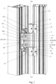
Fig. 1 shows an axonometric view of a first embodiment of the hinge arrangement according to the present invention in an open position with the fragments of the frame and sash profiles; -
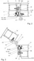
Figs. 2 and 3 show the embodiment shown inFig. 1 with the fragments of the frame and sash profiles in a cross section along a plane perpendicular to the longitudinal hinge axis, respectively in a closed position and in the open position; -
Figs. 4 and 5 show exploded axonometric views of the embodiment ofFig. 1 ; -
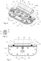
Figs. 6 and 7 show respectively top axonometric and bottom view of the second hinge member of the first hinge arrangement embodiment ofFig. 1 ; -
Fig. 8 shows an axonometric view of an eccentric element of transversal adjusting means of the embodiment ofFig. 1 ; -
Figs. 9 and 10 show the second hinge member ofFig. 6 in a cross section along the plane perpendicular to the longitudinal hinge axis passing through line A-A depicted inFig. 6 , in two different extreme adjustment states of the transversal adjusting means respectively; -
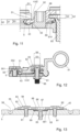
Fig. 11 shows an enlarged view of the part of the figureFig. 10 ; -
Fig. 12 shows the second hinge member ofFig. 6 in a cross section along the plane perpendicular to the longitudinal hinge axis passing through the line B-B depicted inFig. 6 , in a middle adjustment state of the transversal adjusting means; -
Fig. 13 shows the second hinge member ofFig. 6 in a longitudinal section along the plane parallel to the longitudinal hinge axis passing through the line C-C depicted inFig. 6 , -
Fig. 14 shows a bottom axonometric view of the hinge lever of the embodiment ofFig. 1 ; -
Fig. 15 shows a top axonometric view of the base plate of the embodiment ofFig. 1 ; -
Figs. 16, 17 and 18 show respectively second, third and fourth embodiment of the second hinge member of the hinge arrangement according to the present invention in a cross-section along the plane perpendicular to the longitudinal hinge axis passing through the line equivalent to the line A-A depicted inFig. 6 , in a middle adjustment state of the transversal adjusting means; -
Fig. 19 shows an axonometric view of a fifth embodiment of the second hinge member of the hinge arrangement according to the present invention; -
Fig. 20 shows an exploded axonometric view of the second hinge member ofFig. 19 ; -
Fig. 21 shows the second hinge member ofFig. 19 in a cross section along the plane perpendicular to the longitudinal hinge axis passing through the line D-D depicted inFig. 19 , and -
Fig. 22 shows a side view of the second hinge member ofFig. 19 . - The first embodiment of a
hinge arrangement 1 according to the present invention is presented inFigs. 1-15 . In this example, thehinge arrangement 1 serves to hinge a multi-chamber thermalinsulating profile element 72 of a sash, not shown in further details, of an external office door on a multi-chamber thermalinsulating profile element 71 of the frame, not shown in further details. Each of theprofile elements profile elements - The
hinge arrangement 1 comprises twofirst hinge members 2 mounted on the multi-chambersash profile element 72 and connected in an articulated manner to asecond hinge member 3 mounted on the multi-chamberframe profile element 71. - The
first hinge members 2 and thesecond hinge member 3 comprisehinge sleeves hinge members common hinge pin 6 defining the longitudinal hinge axis O1. - The positions of the
hinge sleeves 21 of thefirst hinge members 2 on thehinge pin 6 are set by screwing headless set screws into annular recesses formed on thehinge pin 6. Each of thefirst hinge members 2 comprises amounting part 22 in whichappropriate mounting openings 23 are formed through which mountingscrews 24 are extended and screwed in the box profiles of the multi-chambersash profile element 72. Themounting part 22 comprises an angle bar connected to thehinge sleeve 21 and a thickened mounting foot that adheres to the inner surface of the multi-chambersash profile element 72. The angle bar portion of themounting part 22 is arranged in a corner section of the multi-chambersash profile element 72 and screwed to thesash profile element 72 by means of themounting screws 24 extending through its corner aslant relative to both arms of this angle bar portion. Anothermounting screw 24 of thefirst hinge member 2 is extended through the mounting opening 23 formed in the thickened mounting foot and is screwed aslant at some angle relative to the surface of an inner wall of thesash profile element 72. - Such slanting orientation of the
mounting screws 24 relative to the walls of thesash profile element 72 into which they are screwed, increases the strength of the connection of thefirst hinge members 2 to thesash profile element 72. - The
second hinge member 3 comprises ahinge lever 4 arranged on thehinge pin 6 and connected to abase plate 5 mounted on the inner surface of the multi-chamberframe profile element 71. Thebase plate 5 comprises sixmounting openings 56 through which mountingscrews 57 extend and screw thebase plate 5 to the multi-chamberframe profile element 71. Some of themounting openings 56 extend aslant relative to the surface of adjacency of thebase plate 5 to the wall of theframe profile element 71, and thus somemounting screws 57 are screwed slantwise into the walls of theframe profile element 71 providing an increased mechanical strength of such a connection. - The
base plate 5 comprises alongitudinal blocking channel 51 extended parallel to the longitudinal hinge axis O1 and open through alongitudinal slit 52 in its transverse direction in the plane substantially parallel to the surface of adjacency of thebase plate 5 to theframe profile element 71. In this embodiment thelongitudinal blocking channel 51 and itslongitudinal slit 52 are defined by a firstlongitudinal recess 53 of thebase plate 5 and a secondlongitudinal recess 54 of a blockingplate 55. - The blocking
plate 55 is connected in a decouplable manner to thebase plate 5 by means of mountingscrews 552 extended through its mountingopenings 551 and screwed into thebase plate 5. In order to provide easy positioning of the blockingplate 55 relative to thebase plate 5, thebase plate 5 is provided with two projections that are inserted into the corresponding recesses formed in the blockingplate 55, wherein the mountingscrews 552 of the blockingplate 55 are screwed into thesebase plate 5 projections. - The
hinge lever 4 comprises ahinge sleeve 41 arranged on thehinge pin 6 freely between the fixedhinge sleeves 21 of thefirst hinge members 2, and ahinge leaf 42 mechanically coupled to thebase plate 5. - The
hinge leaf 42 comprises an angle bar portion which is connected to thehinge sleeve 41 and transforms into a plate portion comprising two flat bar portions that are parallel relative to each other. A longitudinal blocking thickenedportion 43 is formed along the outer edge of the second outer flat bar portion of thehinge leaf 42. The second outer flat bar portion of thehinge leaf 42 is inserted through thelongitudinal slit 52 of thelongitudinal blocking channel 51 of thebase plate 5, and the longitudinal blocking thickenedportion 43 is arranged in thelongitudinal blocking channel 51. - The width S1 of the
longitudinal slit 52 of thelongitudinal blocking channel 51 is smaller than the width S2 of the longitudinal blocking thickenedportion 43 and greater than the width S3 of thehinge leaf 42 portion (the second outer flat bar portion) that is extended through thislongitudinal slit 52. Thanks to that, when longitudinal blocking thickenedportion 43 is located in thelongitudinal blocking channel 51, thehinge leaf 42 becomes mechanically coupled and connected to thebase plate 5, as there is no possibility to draw out this longitudinal blocking thickenedportion 43 out of thelongitudinal blocking channel 51 through thelongitudinal slit 52; but there still exists a possibility of rotating thehinge leaf 42 around the longitudinal blocking thickenedportion 43 relative to thebase plate 5 within an angular range defined and limited by the clearance of thehinge leaf portion 42 in thelongitudinal slit 52. - The
longitudinal blocking channel 51 has a non-circular cross-section that is elongated in the transversal direction of an opening of this blockingchannel 51 through thelongitudinal slit 52. The cross-section of the longitudinal blocking thickenedportion 43 is smaller than the cross-section of thelongitudinal blocking channel 51 along the direction of the elongation of thelongitudinal blocking channel 51, and therefore in the direction of thelongitudinal blocking channel 51 elongation the longitudinal blocking thickenedportion 43 fills thelongitudinal blocking channel 51 with some clearance. Thanks to that the longitudinal blocking thickenedportion 43 is linearly moveable and slidable in thelongitudinal blocking channel 51 with changing the depth G1 of an insertion of thehinge leaf 42 into thelongitudinal blocking channel 51 and itslongitudinal slit 52. - Such an elongated configuration of the
longitudinal blocking channel 51 and an appropriate fit of the longitudinal blocking thickenedportion 43 geometry to the blockingchannel 51 with a transverse clearance of the longitudinal blocking thickenedportion 43 in thechannel 51 enables the transversal adjusting means 9 to adjust a position of thehinge leaf 42 relative to thebase plate 5 in the plane of an insertion of thehinge leaf 42 into thelongitudinal blocking channel 51 and itslongitudinal slit 52 in the direction perpendicular to the longitudinal hinge axis O1. Thus the transversal adjusting means 9 provide a possibility of adjusting a position of the sash relative to the frame in the plane of the sash. The transversal adjusting means 9 comprise in this embodiment aneccentric element 91 comprising thebolt 92 arranged in firsteccentric opening 94 in thehinge leaf 42 and aneccentric cam 93 connected to thebolt 91 and arranged in the secondeccentric opening 95 in thebase plate 5. - The
bolt 92 of theeccentric element 91 comprises torque application means 96 that are accessible from an outer side of thehinge leaf 42 that is opposite relative to thebase plate 5, and the rotation of theeccentric element 91 caused using these torque application means 96 changes the depth G1 of an insertion of thehinge leaf 42 into thelongitudinal blocking channel 51 and itslongitudinal slit 52 in the transversal direction of thelongitudinal blocking channel 51 perpendicular to its longitudinal axis. -
Figs. 9 and 10 illustrate two opposite extreme adjustment states of the transversal adjusting means 9 in which thehinge leaf 42 is inserted into thelongitudinal blocking channel 51 and itslongitudinal slit 52 to the maximal and minimal depth G1 respectively. These two extreme positions define the maximal adjustment range of the transversal adjusting means 9. - The first embodiment of the
hinge arrangement 1 is further provided with horizontal adjusting means 8 for adjusting an angular position of thehinge leaf 42 relative to thebase plate 5 by a rotation of thehinge leaf 42 around its longitudinal blocking thickened portion 43 (and thus for adjusting an angular position of the sash relative to the frame that is in particular important for the closed state of the hinge arrangement) and vertical adjusting means 10 for adjusting a vertical position of thehinge leaf 42 relative to thebase plate 5 in the direction parallel to the longitudinal hinge axis O1 (and thus for adjusting a vertical position of the sash relative to the frame that is in particular important for the closed state of the hinge arrangement). - The horizontal adjusting means 8 comprise two first horizontal adjusting screws 81 and one second horizontal adjusting
screw 85 that are mechanically coupled to thehinge leaf 42 and to thebase plate 5 and act on thehinge leaf 42 in the opposite directions. The first horizontal adjusting screws 81 are screwed in thebase plate 5 and extended through the first adjusting throughopenings 82 in thehinge leaf 42. The first horizontal adjusting screws 81 are provided withheads 83 rested against an outer surface of thehinge leaf 42 on its side opposite relative to thebase plate 5 and torque application means 84 accessible from this outer side of thehinge leaf 42. The second horizontal adjustingscrew 85 is screwed in thebase plate 5 between the first horizontal adjusting screws 81. The second horizontal adjustingscrew 85 is rested with itshead 88 against an inner surface of thehinge leaf 42 on its side facing thebase plate 5. Thehead 88 of the second horizontal adjustingscrew 85 is provided with torque application means 86 accessible from the outer side of thehinge leaf 42 through an access throughopening 87 formed in thehinge leaf 42. Thehead 88 of the second horizontal adjustingscrew 85 is arranged with a clearance in the transverse direction in a longitudinal mountingchannel 89 of thehinge leaf 42. Thelongitudinal mounting channel 89 extends parallel to the longitudinal hinge axis O1 and is open through alongitudinal slit 810 facing thebase plate 5. A bolt of the second horizontal adjustingscrew 85 is extended through thelongitudinal slit 810 with a clearance in the transverse direction. Thelongitudinal mounting channel 89 for thehead 88 of the second horizontal adjustingscrew 85 has a thickness G2 that is greater than the thickness G3 of thehead 88. The width S4 of the longitudinal mountingchannel 89 is greater than the diameter D1 of thehead 88 of the second adjustingscrew 85 and therefore there exists a transverse clearance for thehead 88 in the longitudinal mountingchannel 89. A bolt of the second adjustingscrew 85 extends through thelongitudinal slit 810 of the longitudinal mountingchannel 89 with a transverse clearance as the width S5 of thelongitudinal slit 810 is greater than the diameter D2 of the part of the bolt of the second adjustingscrew 85 located in thelongitudinal slit 810. Bolts of the first horizontal adjusting screws 81 extend through the first adjusting throughopenings 82 with a transverse clearance as the width S6 of the first adjusting throughopening 82 is greater than the diameter D3 of the bolt of the first horizontal adjustingscrew 81. The transverse clearances of the bolts of the first horizontal adjusting screws 81 in the first adjusting throughopenings 82 and the transverse clearances of the second horizontal adjustingscrew 85 in the longitudinal mountingchannel 89 and in thelongitudinal slit 810, enable the transversal adjusting means 9 to operate and to change a position of thehinge leaf 42 relative to thebase plate 5 in the plane of an insertion of thehinge leaf 42 into thelongitudinal blocking channel 51 and itslongitudinal slit 52 in the direction perpendicular to the longitudinal hinge axis O1. - All of the first horizontal adjusting screws 81 and the second horizontal adjusting
screw 85 are screwed into a prismatoidlongitudinal projection 58 of thebase plate 5 that extends in parallel relative to the longitudinal hinge axis O1 and is arranged in thelongitudinal slit 810 with a transverse clearance and in the longitudinal mountingchannel 89. In the prismatoidlongitudinal projection 58 of the base plate 5 acentral recess 581 is formed in which thehead 88 of the second horizontal adjustingscrew 85 is arranged. - The vertical adjusting means 10 comprise two vertical adjusting
sleeves 103 and two vertical adjusting screws 101 coupled to thehinge leaf 42 and to thebase plate 5 and acting on thehinge leaf 42 in the opposite directions along the longitudinal hinge axis O1. In order to enable changing a vertical position of thehinge leaf 42 relative to thebase plate 5 in the direction parallel to the longitudinal hinge axis O1 the first adjusting throughopening 82, the access throughopening 87 and one of theeccentric openings 94 have forms of longitudinal openings elongated in the direction parallel to the longitudinal hinge axis O1. The vertical adjustingsleeves 103 provided with internal threads are connected to thebase plate 5 and arranged on the opposite sides of an axiallongitudinal projection 44 of thehinge leaf 42 along the direction parallel to the longitudinal hinge axis O1. The vertical adjusting screws 101 are screwed into the vertical adjustingsleeves 103 and rested against the axiallongitudinal projection 44 of thehinge leaf 42 on both opposite sides thereof, wherein the vertical adjusting screws 101 are provided with torque application means 102 accessible by throughopenings 104 of the vertical adjustingsleeves 103. -
Fig. 16 shows the second embodiment of asecond hinge member 3 of the hinge arrangement according to the present invention. In this second embodiment the second horizontal adjustingscrew 85 is simply rested with itshead 88 against an inner surface of thehinge leaf 42 on its side facing thebase plate 5 without arranging thescrew 85 in any longitudinal mountingchannel 89 and itslongitudinal slit 810 of the first embodiment shown inFigs. 1-15 . -
Fig. 17 shows the third embodiment of asecond hinge member 3 of the hinge arrangement according to the present invention. The second horizontal adjustingscrew 85 has in this embodiment a form of a headless set screw that is screwed in a threaded second adjusting throughopening 811 formed in thehinge leaf 42 of thehinge lever 4 but it is not screwed in thebase plate 5 but simply rests against a surface of thebase plate 5 facing thehinge leaf 42 and thus acts on thehinge leaf 42 in the direction opposite to the direction in which the first adjusting screws act on thehinge leaf 42. Thethird embodiment 3 does not comprise the blockingplate 5 of the first and second embodiments, and comprises thelongitudinal blocking channel 51 and itslongitudinal slit 52 formed directly, integrally and completely in the material of thebase plate 4. -
Fig. 18 shows the fourth embodiment of asecond hinge member 3 of the hinge arrangement according to the present invention in which an axial longitudinaltriangular projection 812 is formed on the upper surface of the longitudinal mountingchannel 89 facing thebase plate 5. The surfaces of this axial longitudinaltriangular projection 812 are inclined at an angle α relative to the opposite bottom surface of the longitudinal mountingchannel 89. Such a configuration improves supporting thehinge leaf 42 by the second adjustingscrew 85 as thehead 88 of the second adjustingscrew 85 is always rested against the apex edge of this axial longitudinaltriangular projection 812 irrespective of an actual angular position of thehinge leaf 42 relative to thebase plate 5 that may be changed using horizontal adjusting means 8. -
Figs. 19-22 show the fifth embodiment of asecond hinge member 3 of the hinge arrangement according to the present invention. This fifth embodiment is similar to the embodiment ofFig. 9 but comprises transversal adjusting means 9 in which theeccentric element 91 is replaced with a transversal adjustingscrew 97. The transversal adjustingscrew 97 is oriented perpendicularly relative to the longitudinal hinge axis O1 and serves for changing the depth of an insertion of thehinge leaf 42 into thelongitudinal blocking channel 51 and itslongitudinal slit 52 in the transversal direction of thelongitudinal blocking channel 51 perpendicular to its longitudinal axis. - The
head 99 of the transversal adjustingscrew 97 is arranged in the first transversal adjustingcavity 911 of thebase plate 5. Thebolt 98 of the transversal adjustingscrew 97 is screwed into atransversal adjusting block 913 arranged in the second transversal adjustingcavity 912 of thehinge leaf 42 and therefore the threadedbolt 98 of the transversal adjustingscrew 97 is coupled with thehinge leaf 42. The first transversal adjustingcavity 911 is connected to the second transversal adjustingcavity 912 through a connectingchannel 914 in which thebolt 98 of the transversal adjustingscrew 97 is arranged. The width of thehead 99 of the transversal adjustingscrew 97 along its longitudinal axis corresponds to the corresponding width of the first transversal adjustingcavity 911 in which it is arranged. Therefore the transversal adjustingscrew 97 is substantially immovable along its longitudinal axis in the first transversal adjustingcavity 911 relative to thebase plate 5. Thetransversal adjusting block 913 constitutes an individual separate part inserted into the second transversal adjustingcavity 912 of thehinge leaf 42, wherein its width along the longitudinal axis of the transversal adjustingscrew 97 substantially corresponds to the corresponding width of the second transversal adjustingcavity 912 of thehinge leaf 42. Additionally, a rectangular prismatoid shape and dimensions of thetransversal adjusting block 913 substantially corresponds to the shape and dimensions of the second transversal adjustingcavity 912 of thehinge leaf 42, and therefore thetransversal adjusting block 913 is substantially immovable inside the second transversal adjustingcavity 912 and a rotation of thetransversal adjusting block 913 around the longitudinal axis of the transversal adjustingscrew 97 is blocked. Therefore the transversal adjustingscrew 97 is substantially linearly immovable relative to thebase plate 5 and to thehinge lever 4, but it may be only rotated furthermore thanks to some small clearance of thehead 99 of the transversal adjustingscrew 97 along its longitudinal axis in the first transversal adjustingcavity 911 its inclination relative to thebase plate 5 may change to a very small extent enabling the horizontal adjusting means 8 to operate. A rotation of the transversal adjustingscrew 97 using its torque application means 910 available through an access throughopening 915 formed in thebase plate 5 does not cause a rotation of thetransversal adjusting block 913 but causes a displacement of thetransversal adjusting block 913 along thebolt 98 of the transversal adjustingscrew 97 and thus also a displacement of thewhole hinge lever 4 relative to thebase plate 5 and a change of the depth of an insertion of thehinge leaf 42 into thelongitudinal blocking channel 51 and itslongitudinal slit 52 in the transversal direction of thelongitudinal blocking channel 51. - In some embodiments of the hinge arrangement according to the present invention that are alternative to the above described fifth embodiment and not shown on the drawings, the threaded bolt of the transversal adjusting screw may be directly coupled with the hinge leaf by screwing it directly into a threaded opening formed in the hinge leaf.
- Some other alternative embodiments of the hinge arrangement according to the present invention that are not shown on the drawings may not comprise vertical adjusting means and therefore in such embodiments the first adjusting through
opening 82, the access throughopening 87 and any of theeccentric openings hinge leaf 42 relative to thebase plate 5 in the direction parallel to the longitudinal hinge axis O1. - All components of the hinge arrangement according to the present invention may be made of any suitable material, that in particular ensures an appropriate mechanical strength of these components. In particular, such components may be made of aluminium and aluminium alloys and manufactured using die casting or extrusion technologies.
- The figures are not necessarily to scale and some features may be exaggerated or minimized. The above embodiments of the present invention are therefore merely exemplary. These and other factors however should not be considered as limiting the spirit of the invention, the intended scope of protection of which is indicated in appended claims.
-
- 1
- hinge arrangement
- 2
- first hinge member
21 hinge sleeve
22 mounting part
23 mounting opening
24 mounting screw - 3
- second hinge member
- 4
- hinge lever
41 hinge sleeve
42 hinge leaf
43 longitudinal blocking thickened portion
44 axial longitudinal projection - 5
- base plate
51 longitudinal blocking channel
52 longitudinal slit of thelongitudinal blocking channel 51
53 first longitudinal recess
54 second longitudinal recess
55 blocking plate
551 mounting opening
552 mounting screw
56 mounting opening
57 mounting screw
58 prismatoid longitudinal projection
581 recess of the prismatoidlongitudinal projection 58 - 6
- hinge pin
- 71
- multi-chamber frame profile element
- 72
- multi-chamber sash profile element
- 8
- horizontal adjusting means
81 first horizontal adjusting screw
82 first adjusting through opening
83 head of the first horizontal adjustingscrew 81
84 torque application means of the first horizontal adjustingscrew 81
85 second horizontal adjusting screw
86 torque application means of the second horizontal adjustingscrew 85
87 access through opening
88 head of the second adjustingscrew 85
89 longitudinal mounting channel
810 longitudinal slit of the longitudinal mountingchannel 89
811 second adjusting through opening
812 axial longitudinal triangular projection of the longitudinal mountingchannel 89 - 9
- transversal adjusting means
91 eccentric element
92 bolt of theeccentric element 91
93 eccentric cam of theeccentric element 91
94 first eccentric opening
95 second eccentric opening
96 torque application means of theeccentric element 91
97 transversal adjusting screw
98 bolt of the transversal adjustingscrew 97
99 head of the transversal adjustingscrew 97
910 torque application means of the transversal adjustingscrew 97
911 first transversal adjusting cavity of thebase plate 5
912 second transversal adjusting cavity of thehinge leaf 42
913 transversal adjusting block
914 connecting channel
915 access through opening - 10
- vertical adjusting means
101 vertical adjusting screw
102 torque application means of the vertical adjustingscrew 101
103 vertical adjusting sleeve
104 access through opening of thevertical adjusting sleeve 103 - O1
- longitudinal hinge axis
- S1
- width of the
longitudinal slit 52 - S2
- width of the longitudinal blocking thickened
portion 43 - S3
- width of the
hinge leaf 42 part extended through thelongitudinal slit 52 - S4
- width of the longitudinal mounting
channel 89 - S5
- width of the
longitudinal slit 810 - S6
- width of the first adjusting through
opening 82 - G1
- depth of an insertion of the
hinge leaf 42 into the blockingchannel 51 - G2
- thickness of the cross-section of the mounting
channel 89 - G3
- thickness of the
head 88 of the second horizontal adjustingscrew 85 - D1
- diameter of the
head 88 of the second adjustingscrew 85 - D2
- diameter of the bolt of the second adjusting
screw 85 - D3
- diameter of the bolt of the first horizontal adjusting
screw 81
Claims (12)
- A hinge arrangement (1), and in particular a door or window hinge arrangement, comprising at least one first hinge member (2) and a second hinge member (3) connected to each other in an articulated manner on a common hinge pin (6) defining a longitudinal hinge axis (O1),wherein the at least one first hinge member (2) comprises a hinge sleeve (21) arranged on the hinge pin (6) and a mounting part (22) apt to be mounted to a frame (71) or a sash (72), andwherein the second hinge member (3) comprisesa base plate (5) apt to be mounted to the sash (72) or the frame (71), anda hinge lever (4) comprising a hinge sleeve (41) arranged on the hinge pin (6) and a hinge leaf (42) mechanically coupled to the base plate (5),wherein the base plate (5) comprises a longitudinal blocking channel (51) extended parallel to the longitudinal hinge axis (O1) and open in its transverse direction through a longitudinal slit (52),and the hinge leaf (4) comprises a longitudinal blocking thickened portion (43) arranged in the longitudinal blocking channel (51) in the base plate (5) and inserted into the longitudinal blocking channel (51) through the longitudinal slit (52) thereof, wherein the width (S1) of the longitudinal slit (52) is smaller than the width (S2) of the longitudinal blocking thickened portion (43) and is greater than the width (S3) of the hinge leaf (42) part extending through the longitudinal slit (52),wherein the hinge arrangement (1) comprises additionally horizontal adjusting means (8) for adjusting an angular position of the hinge leaf (42) relative to the base plate (5) by a rotation of the hinge leaf (42) around its longitudinal blocking thickened portion (43);characterized in that,the longitudinal blocking channel (51) has an elongated non-circular cross-section and the longitudinal blocking thickened portion (43) is moveable in the longitudinal blocking channel (51) with changing the depth (G1) of an insertion of the hinge leaf (42) into the longitudinal blocking channel (51) and its longitudinal slit (52),and the hinge arrangement (1) additionally comprises transversal adjusting means (9) for adjusting a position of the hinge leaf (42) relative to the base plate (5) in the plane of an insertion of the hinge leaf (42) into the longitudinal blocking channel (51) and its longitudinal slit (52) and in the direction perpendicular to the longitudinal hinge axis (O1) by changing the depth (G1) of an insertion of the hinge leaf (42) into the longitudinal blocking channel (51) and its longitudinal slit (52) in a transversal direction substantially perpendicular to the longitudinal blocking channel (51).
- The hinge arrangement (1) according to claim 1, characterized in that, the transversal adjusting means (9) comprise an eccentric element (91) arranged in the first eccentric opening (94) in the hinge leaf (42) and in the second eccentric opening (95) in the base plate (5), wherein a rotation of the eccentric element (91) changes the depth (G1) of an insertion of the hinge leaf (42) into the longitudinal blocking channel (51) and its longitudinal slit (52) in the transversal direction of the longitudinal blocking channel (51).
- The hinge arrangement (1) according to claim 1, characterized in that, the transversal adjusting means (9) comprise a transversal adjusting screw (97) oriented perpendicularly relative to the longitudinal hinge axis (O1), wherein the head (99) of the transversal adjusting screw (97) is arranged in the first transversal adjusting cavity (911) of the base plate (5) and the threaded bolt (98) of the transversal adjusting screw (97) is coupled with the hinge leaf (42), and wherein the width of the head (99) of the transversal adjusting screw (97) along its longitudinal axis corresponds substantially to the corresponding width of the first transversal adjusting cavity (911), and wherein a rotation of the transversal adjusting screw (97) changes the depth (G1) of an insertion of the hinge leaf (42) into the longitudinal blocking channel (51) and its longitudinal slit (52) in the transversal direction of the longitudinal blocking channel (51).
- The hinge arrangement (1) according to claim 3, characterized in that, the bolt (98) of the transversal adjusting screw (97) is screwed into a transversal adjusting block (913) constituting an individual separate part arranged in the second transversal adjusting cavity (912) of the hinge leaf (42) wherein a rotation of the transversal adjusting block (913) around the longitudinal axis of the transversal adjusting screw (97) is blocked.
- The hinge arrangement (1) according to any of Claims 1-4, characterized in that, the longitudinal blocking channel (51) and its longitudinal slit (52) are defined by a first longitudinal recess (53) of the base plate (5) and a second longitudinal recess (54) of a blocking plate (55) connected in a decouplable manner to the base plate (5).
- The hinge arrangement (1) according to any of Claims 1-5, characterized in that, the eccentric element (91) comprises a bolt (92) arranged in the first eccentric opening (94) in the hinge leaf (42) and an eccentric cam (93) connected to the bolt (92) and arranged in the second eccentric opening (95) in the base plate (5).
- The hinge arrangement (1) according to any of Claims 1-6, characterized in that, the horizontal adjusting means (8) comprise at least one adjusting screw (81, 85) coupled to the hinge leaf (42) and to the base plate (5), and preferably comprise at least two horizontal adjusting screws (81, 85) coupled to the hinge leaf (42) and to the base plate (5) and acting on the hinge leaf (42) in the opposite directions.
- The hinge arrangement (1) according to Claim 7, characterized in that, the horizontal adjusting means (8) comprise
at least one first horizontal adjusting screw (81) screwed in the base plate (5) and extended through the first adjusting through opening (82) in the hinge leaf (42) and provided with a head (83) rested against an outer surface of the hinge leaf (42) on its side opposite relative to the base plate (5) and torque application means (84) accessible from this outer side of the hinge leaf (42), and at least one second horizontal adjusting screw (85) screwed in the base plate (5) and rested against an inner surface of the hinge leaf (42) on its side facing the base plate (5) and provided with torque application means (86) accessible from the outer side of the hinge leaf (42) through an access through opening (87) in the hinge leaf (42). - The hinge arrangement (1) according to Claim 8, characterized in that, the second horizontal adjusting screw (85) comprises a head (88) arranged in a mounting channel (89) of the hinge leaf (42) extended parallel to the longitudinal hinge axis (O1) and open through a longitudinal slit (810) facing the base plate (5), wherein a bolt of the second horizontal adjusting screw (85) is extended through the longitudinal slit (810).
- The hinge arrangement (1) according to Claim 9, characterized in that, the longitudinal mounting channel (89) for the head (88) of the second horizontal adjusting screw (85) has the thickness (G2) greater than the thickness (G3) of the head (88) and the width (S4) greater than the diameter (D1) of the head (88).
- The hinge arrangement (1) according to any of Claims 1-10, characterized in that, the hinge arrangement (1) comprises additionally vertical adjusting means (10) for adjusting a vertical position of the hinge leaf (42) relative to the base plate (5) in the direction parallel to the longitudinal hinge axis (O1) and comprising two vertical adjusting screws (101) coupled to the hinge leaf (42) and to the base plate (5) and acting on the hinge leaf (42) in the opposite directions along the direction parallel to the longitudinal hinge axis (O1), and additionally the first adjusting through opening (82), the access through opening (87) and one of the eccentric openings (94, 95) are longitudinal openings elongated in the direction parallel to the longitudinal hinge axis (O1).
- The hinge arrangement (1) according to Claim 11, characterized in that, the vertical adjusting means (10) comprise two vertical adjusting sleeves (103) connected to the base plate (5) and arranged on the opposite sides of the hinge leaf (42) along the direction parallel to the longitudinal hinge axis (O1) and provided with internal threads into which the vertical adjusting screws (101) are screwed in and rested against the hinge leaf (42) on both opposite sides thereof, wherein the vertical adjusting screws (101) are provided with torque application means (102) accessible by through openings (104) of the vertical adjusting sleeves (103).
Priority Applications (5)
| Application Number | Priority Date | Filing Date | Title |
|---|---|---|---|
| PL23169472.0T PL4455431T3 (en) | 2023-04-24 | 2023-04-24 | A hinge arrangement |
| SI202330107T SI4455431T1 (en) | 2023-04-24 | 2023-04-24 | Hinge assembly |
| EP23169472.0A EP4455431B1 (en) | 2023-04-24 | 2023-04-24 | A hinge arrangement |
| PT231694720T PT4455431T (en) | 2023-04-24 | 2023-04-24 | A hinge arrangement |
| ES23169472T ES3067378T3 (en) | 2023-04-24 | 2023-04-24 | A hinge arrangement |
Applications Claiming Priority (1)
| Application Number | Priority Date | Filing Date | Title |
|---|---|---|---|
| EP23169472.0A EP4455431B1 (en) | 2023-04-24 | 2023-04-24 | A hinge arrangement |
Publications (2)
| Publication Number | Publication Date |
|---|---|
| EP4455431A1 true EP4455431A1 (en) | 2024-10-30 |
| EP4455431B1 EP4455431B1 (en) | 2026-03-11 |
Family
ID=86184887
Family Applications (1)
| Application Number | Title | Priority Date | Filing Date |
|---|---|---|---|
| EP23169472.0A Active EP4455431B1 (en) | 2023-04-24 | 2023-04-24 | A hinge arrangement |
Country Status (5)
| Country | Link |
|---|---|
| EP (1) | EP4455431B1 (en) |
| ES (1) | ES3067378T3 (en) |
| PL (1) | PL4455431T3 (en) |
| PT (1) | PT4455431T (en) |
| SI (1) | SI4455431T1 (en) |
Citations (3)
| Publication number | Priority date | Publication date | Assignee | Title |
|---|---|---|---|---|
| EP2105561A2 (en) * | 2008-03-29 | 2009-09-30 | Bartels Systembeschläge GmbH | Hinge for hidden installation with three-dimensional adjustment and interior adjustment unit |
| EP2725174A1 (en) * | 2012-10-29 | 2014-04-30 | Dr. Hahn GmbH & Co. KG | Assembly of a hinge |
| DE102018115806B3 (en) * | 2018-06-29 | 2019-05-29 | Dr. Hahn Gmbh & Co. Kg | Assembly of a band hinged about a hinge axis connecting a wing with a frame and tape with this assembly |
-
2023
- 2023-04-24 ES ES23169472T patent/ES3067378T3/en active Active
- 2023-04-24 PT PT231694720T patent/PT4455431T/en unknown
- 2023-04-24 EP EP23169472.0A patent/EP4455431B1/en active Active
- 2023-04-24 SI SI202330107T patent/SI4455431T1/en unknown
- 2023-04-24 PL PL23169472.0T patent/PL4455431T3/en unknown
Patent Citations (4)
| Publication number | Priority date | Publication date | Assignee | Title |
|---|---|---|---|---|
| EP2105561A2 (en) * | 2008-03-29 | 2009-09-30 | Bartels Systembeschläge GmbH | Hinge for hidden installation with three-dimensional adjustment and interior adjustment unit |
| EP2725174A1 (en) * | 2012-10-29 | 2014-04-30 | Dr. Hahn GmbH & Co. KG | Assembly of a hinge |
| EP3613931B1 (en) | 2012-10-29 | 2021-06-30 | Dr. Hahn GmbH & Co. KG | Assembly of a belt for connecting a leaf with a frame hinged around a hinge axis |
| DE102018115806B3 (en) * | 2018-06-29 | 2019-05-29 | Dr. Hahn Gmbh & Co. Kg | Assembly of a band hinged about a hinge axis connecting a wing with a frame and tape with this assembly |
Also Published As
| Publication number | Publication date |
|---|---|
| PT4455431T (en) | 2026-05-05 |
| EP4455431B1 (en) | 2026-03-11 |
| SI4455431T1 (en) | 2026-07-31 |
| PL4455431T3 (en) | 2026-07-20 |
| ES3067378T3 (en) | 2026-05-21 |
Similar Documents
| Publication | Publication Date | Title |
|---|---|---|
| US6735823B2 (en) | Hinge | |
| BR112020008670B1 (en) | SIDE WALL FOR A FURNITURE BODY AND FURNITURE WITH A FURNITURE BODY | |
| US3318047A (en) | Combination sliding and pivoted door | |
| CA2919343C (en) | Continuous hinge | |
| US4980946A (en) | Jointed fitting for a swing frame of a door, window or the like | |
| ITTO990521A1 (en) | HINGE FOR OPENABLE FRAMES | |
| US12134925B2 (en) | Door hinge | |
| EP4455431B1 (en) | A hinge arrangement | |
| CA2622243A1 (en) | Anti-effraction safety system for door and window frames | |
| EP0790379B1 (en) | Cam adjusting device for iron fittings for furniture and iron fittings with such device | |
| PL234649B1 (en) | Hinge system, and preferably the concealed hinge system | |
| US20080052873A1 (en) | Adjustable hinge | |
| DE202012102978U1 (en) | Band arrangement for doors, windows or the like | |
| RU2698228C1 (en) | Adjustable loop | |
| CZ20009A3 (en) | Arrangement of forging element | |
| PL231737B1 (en) | Hinge system, preferably the concealed hinge system | |
| RU204239U1 (en) | ADJUSTABLE HINGE FOR WINDOW OR DOOR STRUCTURES | |
| JPH03187486A (en) | Door hinge | |
| CA3020835C (en) | End load arm | |
| PT2267258T (en) | UNIT WITH A SLIDING SHEET AND A HARDWARE | |
| CZ298226B6 (en) | Fixing device for a fitting element | |
| JP3211734B2 (en) | Screen box | |
| DE202006002236U1 (en) | Tape for doors, windows or the like | |
| CA2445927A1 (en) | Hinge for doors and similar construction components | |
| EP3914134B1 (en) | An adjustable retention device and a frame assembly comprising the adjustable retention device |
Legal Events
| Date | Code | Title | Description |
|---|---|---|---|
| PUAI | Public reference made under article 153(3) epc to a published international application that has entered the european phase |
Free format text: ORIGINAL CODE: 0009012 |
|
| STAA | Information on the status of an ep patent application or granted ep patent |
Free format text: STATUS: THE APPLICATION HAS BEEN PUBLISHED |
|
| AK | Designated contracting states |
Kind code of ref document: A1 Designated state(s): AL AT BE BG CH CY CZ DE DK EE ES FI FR GB GR HR HU IE IS IT LI LT LU LV MC ME MK MT NL NO PL PT RO RS SE SI SK SM TR |
|
| STAA | Information on the status of an ep patent application or granted ep patent |
Free format text: STATUS: REQUEST FOR EXAMINATION WAS MADE |
|
| 17P | Request for examination filed |
Effective date: 20250430 |
|
| GRAP | Despatch of communication of intention to grant a patent |
Free format text: ORIGINAL CODE: EPIDOSNIGR1 |
|
| STAA | Information on the status of an ep patent application or granted ep patent |
Free format text: STATUS: GRANT OF PATENT IS INTENDED |
|
| INTG | Intention to grant announced |
Effective date: 20251008 |
|
| GRAS | Grant fee paid |
Free format text: ORIGINAL CODE: EPIDOSNIGR3 |
|
| GRAA | (expected) grant |
Free format text: ORIGINAL CODE: 0009210 |
|
| STAA | Information on the status of an ep patent application or granted ep patent |
Free format text: STATUS: THE PATENT HAS BEEN GRANTED |
|
| AK | Designated contracting states |
Kind code of ref document: B1 Designated state(s): AL AT BE BG CH CY CZ DE DK EE ES FI FR GB GR HR HU IE IS IT LI LT LU LV MC ME MK MT NL NO PL PT RO RS SE SI SK SM TR |
|
| REG | Reference to a national code |
Ref country code: CH Ref legal event code: F10 Free format text: ST27 STATUS EVENT CODE: U-0-0-F10-F00 (AS PROVIDED BY THE NATIONAL OFFICE) Effective date: 20260311 Ref country code: GB Ref legal event code: FG4D |
|
| RIN1 | Information on inventor provided before grant (corrected) |
Inventor name: WALA, IRENEUSZ Inventor name: JEDRUSIK, ADRIAN |
|
| REG | Reference to a national code |
Ref country code: DE Ref legal event code: R096 Ref document number: 602023013209 Country of ref document: DE |
|
| REG | Reference to a national code |
Ref country code: IE Ref legal event code: FG4D Ref country code: NL Ref legal event code: FP |
|
| P01 | Opt-out of the competence of the unified patent court (upc) registered |
Free format text: CASE NUMBER: UPC_APP_0010753_4455431/2026 Effective date: 20260324 |
|
| REG | Reference to a national code |
Ref country code: PT Ref legal event code: SC4A Ref document number: 4455431 Country of ref document: PT Date of ref document: 20260505 Kind code of ref document: T Free format text: AVAILABILITY OF NATIONAL TRANSLATION Effective date: 20260428 |
|
| PGFP | Annual fee paid to national office [announced via postgrant information from national office to epo] |
Ref country code: NL Payment date: 20260420 Year of fee payment: 4 |
|
| REG | Reference to a national code |
Ref country code: ES Ref legal event code: FG2A Ref document number: 3067378 Country of ref document: ES Kind code of ref document: T3 Effective date: 20260521 |
|
| REG | Reference to a national code |
Ref country code: GR Ref legal event code: EP Ref document number: 20260400694 Country of ref document: GR Effective date: 20260512 |
|
| PG25 | Lapsed in a contracting state [announced via postgrant information from national office to epo] |
Ref country code: RS Free format text: LAPSE BECAUSE OF FAILURE TO SUBMIT A TRANSLATION OF THE DESCRIPTION OR TO PAY THE FEE WITHIN THE PRESCRIBED TIME-LIMIT Effective date: 20260611 |
|
| PGFP | Annual fee paid to national office [announced via postgrant information from national office to epo] |
Ref country code: ES Payment date: 20260617 Year of fee payment: 4 |
|
| PGFP | Annual fee paid to national office [announced via postgrant information from national office to epo] |
Ref country code: PL Payment date: 20260610 Year of fee payment: 4 |
|
| PGFP | Annual fee paid to national office [announced via postgrant information from national office to epo] |
Ref country code: IT Payment date: 20260430 Year of fee payment: 4 Ref country code: GR Payment date: 20260421 Year of fee payment: 4 |
|
| REG | Reference to a national code |
Ref country code: LT Ref legal event code: MG9D |
|
| PG25 | Lapsed in a contracting state [announced via postgrant information from national office to epo] |
Ref country code: LT Free format text: LAPSE BECAUSE OF FAILURE TO SUBMIT A TRANSLATION OF THE DESCRIPTION OR TO PAY THE FEE WITHIN THE PRESCRIBED TIME-LIMIT Effective date: 20260311 |
|
| PGFP | Annual fee paid to national office [announced via postgrant information from national office to epo] |
Ref country code: DE Payment date: 20260422 Year of fee payment: 4 |
|
| PG25 | Lapsed in a contracting state [announced via postgrant information from national office to epo] |
Ref country code: NO Free format text: LAPSE BECAUSE OF FAILURE TO SUBMIT A TRANSLATION OF THE DESCRIPTION OR TO PAY THE FEE WITHIN THE PRESCRIBED TIME-LIMIT Effective date: 20260611 |
|
| PG25 | Lapsed in a contracting state [announced via postgrant information from national office to epo] |
Ref country code: FI Free format text: LAPSE BECAUSE OF FAILURE TO SUBMIT A TRANSLATION OF THE DESCRIPTION OR TO PAY THE FEE WITHIN THE PRESCRIBED TIME-LIMIT Effective date: 20260311 Ref country code: SE Free format text: LAPSE BECAUSE OF FAILURE TO SUBMIT A TRANSLATION OF THE DESCRIPTION OR TO PAY THE FEE WITHIN THE PRESCRIBED TIME-LIMIT Effective date: 20260311 |
|
| PGFP | Annual fee paid to national office [announced via postgrant information from national office to epo] |
Ref country code: BE Payment date: 20260420 Year of fee payment: 4 |
|
| PG25 | Lapsed in a contracting state [announced via postgrant information from national office to epo] |
Ref country code: HR Free format text: LAPSE BECAUSE OF FAILURE TO SUBMIT A TRANSLATION OF THE DESCRIPTION OR TO PAY THE FEE WITHIN THE PRESCRIBED TIME-LIMIT Effective date: 20260311 |
|
| PGFP | Annual fee paid to national office [announced via postgrant information from national office to epo] |
Ref country code: PT Payment date: 20260506 Year of fee payment: 4 |
|
| PGFP | Annual fee paid to national office [announced via postgrant information from national office to epo] |
Ref country code: TR Payment date: 20260601 Year of fee payment: 4 |
|
| PGFP | Annual fee paid to national office [announced via postgrant information from national office to epo] |
Ref country code: FR Payment date: 20260505 Year of fee payment: 4 |
|
| PG25 | Lapsed in a contracting state [announced via postgrant information from national office to epo] |
Ref country code: LV Free format text: LAPSE BECAUSE OF FAILURE TO SUBMIT A TRANSLATION OF THE DESCRIPTION OR TO PAY THE FEE WITHIN THE PRESCRIBED TIME-LIMIT Effective date: 20260311 |
|
| PG25 | Lapsed in a contracting state [announced via postgrant information from national office to epo] |
Ref country code: BG Free format text: LAPSE BECAUSE OF FAILURE TO SUBMIT A TRANSLATION OF THE DESCRIPTION OR TO PAY THE FEE WITHIN THE PRESCRIBED TIME-LIMIT Effective date: 20260311 |
|
| PGFP | Annual fee paid to national office [announced via postgrant information from national office to epo] |
Ref country code: SI Payment date: 20260416 Year of fee payment: 4 |