EP4455416A1 - Flush toilet - Google Patents
Flush toilet Download PDFInfo
- Publication number
- EP4455416A1 EP4455416A1 EP24171828.7A EP24171828A EP4455416A1 EP 4455416 A1 EP4455416 A1 EP 4455416A1 EP 24171828 A EP24171828 A EP 24171828A EP 4455416 A1 EP4455416 A1 EP 4455416A1
- Authority
- EP
- European Patent Office
- Prior art keywords
- flow channel
- water
- overflow
- storage tank
- wash water
- Prior art date
- Legal status (The legal status is an assumption and is not a legal conclusion. Google has not performed a legal analysis and makes no representation as to the accuracy of the status listed.)
- Pending
Links
- XLYOFNOQVPJJNP-UHFFFAOYSA-N water Substances O XLYOFNOQVPJJNP-UHFFFAOYSA-N 0.000 claims abstract description 302
- 238000011144 upstream manufacturing Methods 0.000 claims abstract description 40
- 239000002699 waste material Substances 0.000 claims abstract description 16
- 230000008878 coupling Effects 0.000 description 8
- 238000010168 coupling process Methods 0.000 description 8
- 238000005859 coupling reaction Methods 0.000 description 8
- 239000000919 ceramic Substances 0.000 description 5
- 239000011347 resin Substances 0.000 description 4
- 229920005989 resin Polymers 0.000 description 4
- 238000011010 flushing procedure Methods 0.000 description 3
- 230000000694 effects Effects 0.000 description 2
- 230000002708 enhancing effect Effects 0.000 description 2
- 230000007257 malfunction Effects 0.000 description 2
- 238000012986 modification Methods 0.000 description 2
- 230000004048 modification Effects 0.000 description 2
- 238000005381 potential energy Methods 0.000 description 2
- 230000015556 catabolic process Effects 0.000 description 1
- 238000006731 degradation reaction Methods 0.000 description 1
- 238000012856 packing Methods 0.000 description 1
Images



Classifications
-
- E—FIXED CONSTRUCTIONS
- E03—WATER SUPPLY; SEWERAGE
- E03D—WATER-CLOSETS OR URINALS WITH FLUSHING DEVICES; FLUSHING VALVES THEREFOR
- E03D1/00—Water flushing devices with cisterns ; Setting up a range of flushing devices or water-closets; Combinations of several flushing devices
- E03D1/24—Low-level flushing systems
-
- E—FIXED CONSTRUCTIONS
- E03—WATER SUPPLY; SEWERAGE
- E03D—WATER-CLOSETS OR URINALS WITH FLUSHING DEVICES; FLUSHING VALVES THEREFOR
- E03D11/00—Other component parts of water-closets, e.g. noise-reducing means in the flushing system, flushing pipes mounted in the bowl, seals for the bowl outlet, devices preventing overflow of the bowl contents; devices forming a water seal in the bowl after flushing, devices eliminating obstructions in the bowl outlet or preventing backflow of water and excrements from the waterpipe
- E03D11/02—Water-closet bowls ; Bowls with a double odour seal optionally with provisions for a good siphonic action; siphons as part of the bowl
-
- E—FIXED CONSTRUCTIONS
- E03—WATER SUPPLY; SEWERAGE
- E03D—WATER-CLOSETS OR URINALS WITH FLUSHING DEVICES; FLUSHING VALVES THEREFOR
- E03D1/00—Water flushing devices with cisterns ; Setting up a range of flushing devices or water-closets; Combinations of several flushing devices
- E03D1/30—Valves for high or low level cisterns; Their arrangement ; Flushing mechanisms in the cistern, optionally with provisions for a pre-or a post- flushing and for cutting off the flushing mechanism in case of leakage
- E03D1/32—Arrangement of inlet valves
-
- E—FIXED CONSTRUCTIONS
- E03—WATER SUPPLY; SEWERAGE
- E03D—WATER-CLOSETS OR URINALS WITH FLUSHING DEVICES; FLUSHING VALVES THEREFOR
- E03D1/00—Water flushing devices with cisterns ; Setting up a range of flushing devices or water-closets; Combinations of several flushing devices
- E03D1/30—Valves for high or low level cisterns; Their arrangement ; Flushing mechanisms in the cistern, optionally with provisions for a pre-or a post- flushing and for cutting off the flushing mechanism in case of leakage
- E03D1/33—Adaptations or arrangements of floats
-
- E—FIXED CONSTRUCTIONS
- E03—WATER SUPPLY; SEWERAGE
- E03D—WATER-CLOSETS OR URINALS WITH FLUSHING DEVICES; FLUSHING VALVES THEREFOR
- E03D1/00—Water flushing devices with cisterns ; Setting up a range of flushing devices or water-closets; Combinations of several flushing devices
- E03D1/30—Valves for high or low level cisterns; Their arrangement ; Flushing mechanisms in the cistern, optionally with provisions for a pre-or a post- flushing and for cutting off the flushing mechanism in case of leakage
- E03D1/34—Flushing valves for outlets; Arrangement of outlet valves
-
- E—FIXED CONSTRUCTIONS
- E03—WATER SUPPLY; SEWERAGE
- E03D—WATER-CLOSETS OR URINALS WITH FLUSHING DEVICES; FLUSHING VALVES THEREFOR
- E03D1/00—Water flushing devices with cisterns ; Setting up a range of flushing devices or water-closets; Combinations of several flushing devices
- E03D1/30—Valves for high or low level cisterns; Their arrangement ; Flushing mechanisms in the cistern, optionally with provisions for a pre-or a post- flushing and for cutting off the flushing mechanism in case of leakage
- E03D1/36—Associated working of inlet and outlet valves
-
- E—FIXED CONSTRUCTIONS
- E03—WATER SUPPLY; SEWERAGE
- E03D—WATER-CLOSETS OR URINALS WITH FLUSHING DEVICES; FLUSHING VALVES THEREFOR
- E03D11/00—Other component parts of water-closets, e.g. noise-reducing means in the flushing system, flushing pipes mounted in the bowl, seals for the bowl outlet, devices preventing overflow of the bowl contents; devices forming a water seal in the bowl after flushing, devices eliminating obstructions in the bowl outlet or preventing backflow of water and excrements from the waterpipe
- E03D11/02—Water-closet bowls ; Bowls with a double odour seal optionally with provisions for a good siphonic action; siphons as part of the bowl
- E03D11/06—Bowls with downwardly-extending flanges for the sake of flushing
-
- E—FIXED CONSTRUCTIONS
- E03—WATER SUPPLY; SEWERAGE
- E03D—WATER-CLOSETS OR URINALS WITH FLUSHING DEVICES; FLUSHING VALVES THEREFOR
- E03D11/00—Other component parts of water-closets, e.g. noise-reducing means in the flushing system, flushing pipes mounted in the bowl, seals for the bowl outlet, devices preventing overflow of the bowl contents; devices forming a water seal in the bowl after flushing, devices eliminating obstructions in the bowl outlet or preventing backflow of water and excrements from the waterpipe
- E03D11/02—Water-closet bowls ; Bowls with a double odour seal optionally with provisions for a good siphonic action; siphons as part of the bowl
- E03D11/08—Bowls with means producing a flushing water swirl
-
- E—FIXED CONSTRUCTIONS
- E03—WATER SUPPLY; SEWERAGE
- E03D—WATER-CLOSETS OR URINALS WITH FLUSHING DEVICES; FLUSHING VALVES THEREFOR
- E03D11/00—Other component parts of water-closets, e.g. noise-reducing means in the flushing system, flushing pipes mounted in the bowl, seals for the bowl outlet, devices preventing overflow of the bowl contents; devices forming a water seal in the bowl after flushing, devices eliminating obstructions in the bowl outlet or preventing backflow of water and excrements from the waterpipe
- E03D11/13—Parts or details of bowls; Special adaptations of pipe joints or couplings for use with bowls, e.g. provisions in bowl construction preventing backflow of waste-water from the bowl in the flushing pipe or cistern, provisions for a secondary flushing, for noise-reducing
-
- E—FIXED CONSTRUCTIONS
- E03—WATER SUPPLY; SEWERAGE
- E03D—WATER-CLOSETS OR URINALS WITH FLUSHING DEVICES; FLUSHING VALVES THEREFOR
- E03D5/00—Special constructions of flushing devices, e.g. closed flushing system
- E03D5/01—Special constructions of flushing devices, e.g. closed flushing system using flushing pumps
Definitions
- Embodiments of the disclosure relate to a flush toilet.
- a flush toilet has conventionally been known that is washed with wash water to discharge waste and includes a water storage tank that stores wash water, a wash water supply flow channel that extends from the water storage tank to a toilet main body, and an overflow flow channel that allows wash water to overflow when wash water inside the water storage tank exceeds a specified water level (e.g., see Patent Documents 1 and 2).
- wash water flows through a rim conduit and is discharged to the inside of a bowl of a toilet main body that receives waste to cause wash water inside a water storage tank to overflow.
- an overflow bypass flow channel extending from an upper part of a water storage tank is connected to a discharge flow channel at a downstream side of a place where a water seal is formed inside a discharge trap conduit, so as to cause wash water inside the water storage tank to overflow.
- any conventional flush toilet as described above has room for further improvement in terms of enhancing overflow performance thereof.
- An object of an aspect of an embodiment is to provide a flush toilet that is capable of enhancing an overflow performance thereof.
- a flush toilet is a flush toilet that is washed with wash water to discharge waste and includes a water storage tank that stores wash water, a toilet main body including a bowl that receives waste, a spout port that spouts wash water to an inside of the bowl, and a discharge trap including an inlet connected to a lower part of the bowl and forming a part of a discharge flow channel that discharges waste inside the bowl, a wash water supply flow channel extending from the water storage tank to the toilet main body, and an overflow flow channel that allows wash water to overflow when wash water inside the water storage tank exceeds a specified water level, wherein the overflow flow channel includes an upstream end part extending to a position between the water storage tank and a water supply opening that supplies the water storage tank with wash water, and at least a part of wash water from the water supply opening directly flows into the upstream end part at a time of occurrence of overflow thereof.
- the upstream end part of the overflow flow channel overlaps with the water supply opening in a top view.
- wash water from the water supply opening flows through the overflow flow channel. This makes it possible to use force of wash water supplied from the water supply opening to the water storage tank at a time of occurrence of overflow thereof, so that wash water reliably flows through the overflow flow channel.
- the overflow flow channel includes a switching mechanism that forms the overflow flow channel at a time of occurrence of overflow thereof to receive wash water from the water supply opening at a higher position than when wash water flows normally.
- a flow channel of wash water is switched between a time of occurrence of overflow thereof and a time when wash water flows normally and no overflow occurs so as to form an overflow flow channel at a time of occurrence of overflow thereof.
- Wash water from the water supply opening is supplied to the overflow flow channel at a time of occurrence of overflow thereof, so that the wash water from the water supply opening flows through the overflow flow channel.
- the switching mechanism includes a float to form the overflow flow channel depending on a water level inside the water storage tank.
- the switching mechanism is configured to rotate depending on a water level inside the water storage tank.
- the switching mechanism has a compact and simple configuration so as to reduce malfunctions thereof, so that it is possible to form an overflow flow channel reliably at a time of occurrence of overflow thereof.
- the switching mechanism includes a movable part that is rotatable depending on a water level inside the water storage tank, and at a time of occurrence of overflow thereof, an upstream end side of the movable part is positioned inside the overflow flow channel, and a downstream end side of the movable part is positioned outside the overflow flow channel.
- an overflow flow channel is formed by stopping a rotational operation of the switching mechanism at a specified position, so that it is possible to form an overflow flow channel reliably at a time of occurrence of overflow thereof.
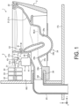
- FIG. 1 is a schematic side view illustrating an overall configuration of the flush toilet 1 according to the embodiment.
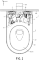
- FIG. 2 is a schematic plan view illustrating an overall configuration of the flush toilet 1 according to the embodiment.
- FIG. 3 is a schematic perspective view illustrating a water storage tank 41 and a wash water supply flow channel 5.
- FIGS. 1 to 3 may illustrate a three-dimensional Cartesian coordinate system that includes a Z-axis with a positive direction that is a vertically upward direction (an upper side).
- a positive direction of an X-axis may be defined as a left side
- a negative direction of the X-axis may be defined as a right side
- a positive direction of a Y-axis may be defined as a front side
- a negative direction of the Y-axis may be defined as a back side
- X-axis directions may be referred to as left-right directions
- Y-axis directions may be referred to as front-back directions
- Z-axis directions may be referred to as up-down directions.
- the flush toilet 1 includes a toilet main body 2, a water supply part 3, a tank 4, the wash water supply flow channel 5, and an overflow flow channel 6.
- the flush toilet 1 is a so-called wall-mounted flush toilet in which the toilet main body 2 described later is fixed to a wall surface WS (or a front wall surface of a cabinet or the like) of a toilet room.
- the toilet main body 2 is made of ceramic.
- the toilet main body 2 is not limited to being made of ceramic and may be made of resin or a combination of ceramic and resin, for example.
- the toilet main body 2 includes a bowl 21, a rim 22, a spout port 23, a discharge trap 24, and a skirt 27.
- the bowl 21 is formed in a recessed shape.
- the bowl 21 includes a bowl surface 21a that receives waste.
- the rim 22 is provided at an upper part of the bowl 21.
- the rim 22 is provided at an upper edge part of the bowl surface 21a.
- the spout port 23 is formed inside the bowl 21 and discharges wash water from the tank 4 to the bowl surface 21a inside the bowl 21.
- the discharge trap 24 forms a part of a discharge flow channel that discharges waste inside the bowl 21.
- One end side of the discharge trap 24 is connected to a lower part of the bowl 21, and the other end side thereof is connected to a discharge pipe 25.
- the one end side of the discharge trap 24 is an inlet 24a of the discharge trap 24 and also serves as an inlet of the discharge flow channel.
- the discharge trap 24 includes a bent pipe 24b and a descending pipe 24c from an upstream side to a downstream side thereof.
- an inlet on the upstream side (inlet 24a of the discharge trap 24) is connected to a lower part of the bowl 21.
- a discharge flow channel is formed that extends backward and downward from the inlet 24a to a lowest end part and then ascends to a back and upper top part 24e.
- the descending pipe 24c forms a discharge flow channel that descends backward and downward from the top part 24e of the bent pipe 24b and is then connected to a discharge socket 26.
- a water seal (water seal surface WL0) is formed in a region on an upstream side (front side) of the top part 24e in the bent pipe 24b.
- the discharge pipe 25 connected to the other end side of the discharge trap 24 extends from a lower side of a floor surface FS to an upper side thereof and then bends toward a toilet main body 2 side (front side), and an inlet positioned at an upstream end of the discharge pipe 25 is connected to an exit 24f at a downstream end of the discharge trap 24 via the discharge socket 26.
- the skirt 27 is provided so as to surround the bowl 21 and the discharge trap 24 from the outside.
- the skirt 27 is not limited to being a ceramic member provided integrally with the toilet main body 2 and may be, for example, a panel member made of resin or the like, provided separately from the toilet main body 2, and detachably attached to the toilet main body 2so as to cover the toilet main body 2 from the outside.
- the water supply part 3 includes a water supply pipe 31.
- the water supply pipe 31 supplies wash water to the tank 4 described later.
- An upstream end side of the water supply pipe 31 is connected to a water supply source 32 such as a water supply.
- the water supply pipe 31 includes a stop cock 33 and a valve unit 34 in order from the water supply source 32 to a downstream side thereof.
- the valve unit 34 includes a fixed flow valve (not illustrated), a diaphragm valve (not illustrated) that is an on-off valve provided on a downstream side of the fixed flow valve, and a solenoid valve (not illustrated) that opens and closes the diaphragm valve.
- a water supply nozzle 31a is provided at a downstream end of the water supply pipe 31.
- the water supply nozzle 31a includes a water supply opening 31b that supplies wash water to the water storage tank 41 (see FIG. 3 ) described later.
- wash water supplied from the water supply source 32 to the water supply pipe 31 by a water supply pressure of a water supply or the like passes through the stop cock 33 and the fixed flow valve of the valve unit 34 where a flow rate thereof is adjusted to be constant, and then passes through the diaphragm valve.
- wash water having passed through the valve unit 34 falls from the water supply opening 31b of the water supply nozzle 31a so as to be supplied from a supply opening 41a of the water storage tank 41 to an inside of the water storage tank 41.
- the tank 4 includes the water storage tank 41 and a pressurizing pump 42.
- the water storage tank 41 stores wash water supplied from the water supply opening 31b.
- the water storage tank 41 is incorporated into a lower part of the toilet main body 2. Wash water supplied from the water supply opening 31b is supplied to the inside of the water storage tank 41 (see FIG. 3 ), as described above.
- the water storage tank 41 includes the supply opening 41a that is an inlet for wash water from the water supply opening 31b at the upper surface of the water storage tank 41.
- the pressurizing pump 42 pressurizes wash water from the water storage tank 41 so as to supply the wash water to the bowl 21 of the toilet main body 2.
- the pressurizing pump 42 is incorporated into the inside of the toilet main body 2.
- wash water supplied to the inside of the water storage tank 41 flows through the wash water supply flow channel 5 described later, is supplied to the toilet main body 2, and further, flows through a main water conduit (not illustrated) provided in the toilet main body 2 and is supplied from the spout port 23 (also referred to as a rim spout port) to the inside of the bowl 21 (bowl surface 21a).
- the flush toilet 1 also includes a controller (not illustrated) that controls an operation of the pressurizing pump.
- the controller may be provided at any position of the toilet main body 2.
- the water supply part 3 includes a float switch (not illustrated) that detects a water level inside the tank.
- An open/close operation of the solenoid valve of the valve unit 34 is controlled by the controller on the basis of a water level inside a coupling unit 43 that is detected by the float switch.
- the coupling unit 43 is provided above the water storage tank 41.
- the coupling unit 43 forms a substantially closed space including the water supply opening 31b and the supply opening 41a of the water storage tank 41.
- An operation of the pressurizing pump 42 is also controlled by the controller on the basis of a water level inside the tank that is detected by the float switch. For example, when a water level inside the coupling unit 43 that is detected by the float switch is equal to or less than a predetermined level, the solenoid valve of the valve unit 34 is opened and the diaphragm valve is opened. Accordingly, the water supply opening 31b of the water supply nozzle 31a is opened, and supply of wash water from the water supply opening 31b to the water storage tank 41 is started.
- the pressurizing pump 42 is operated, so that wash water inside the water storage tank 41 is pumped from the pressurizing pump 42 to the main water conduit of the toilet main body 2, then flows through the rim conduit, and is supplied to the spout port 23.
- toilet flushing is executed by water spouting from the spout port 23 (rim water spouting), that is, toilet flushing based on a so-called "100% rim water spouting toilet flushing" is executed.
- rim water spouting rim water spouting
- the solenoid valve of the valve unit 34 is closed and the diaphragm valve is closed. Accordingly, the water supply opening 31b is blocked and the pressurizing pump 42 is stopped.
- the wash water supply flow channel 5 is a flow channel extending from the water storage tank 41 to the toilet main body 2.
- the wash water supply flow channel 5 is a flow channel through which wash water pressurized by the pressurizing pump 42 flows toward the toilet main body 2.
- a downstream end side of the wash water supply flow channel 5 is connected to the spout port 23 via the rim conduit.
- the wash water supply flow channel 5 includes a spout end 51 on the downstream end side of the wash water supply flow channel 5.
- the wash water supply flow channel 5 may include the rim conduit (not illustrated) of the toilet main body 2.
- the overflow flow channel 6 is a flow channel that allows, when wash water supplied to the water storage tank 41 exceeds a specified water level WL1 (see FIG. 6 ), such wash water to overflow.
- the overflow flow channel 6 includes an upstream end part 61 described later that extends to a position between the water storage tank 41 and the water supply opening 31b. In the overflow flow channel 6, at least a part of wash water from the water supply opening 3 1b directly flows into the upstream end part 61 of such an overflow flow channel 6 at a time of occurrence of overflow thereof.
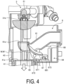
- FIG. 4 is a schematic cross-sectional side view illustrating the water supply opening 31b, the water storage tank 41, and the overflow flow channel 6, and is a view illustrating a normal state of the overflow flow channel 6.
- FIG. 5 is a schematic perspective view illustrating the water storage tank 41 and the overflow flow channel 6.
- FIG. 6 is a schematic cross-sectional side view illustrating the water supply opening 31b, the water storage tank 41, and the overflow flow channel 6, and is a view illustrating a state of the overflow flow channel 6 at a time of occurrence of overflow thereof.
- FIGS. 4 and 6 are also schematic cross-sectional views taken along line IV-IV in FIG. 2 .
- the overflow flow channel 6 includes the upstream end part 61, a downstream end part 62 (see FIG. 3 ), an intermediate part 63 (see FIG. 3 ), and a switching mechanism 64.
- the upstream end part 61 is a site of the overflow flow channel 6 that is positioned inside the coupling unit 43 and extends to a position between the water storage tank 41 and the water supply opening 31b in a side view.
- the upstream end part 61 includes a receiving opening 61a that receives wash water W (W1, W2) from the water supply opening 31b of the water supply pipe 31.
- the receiving opening 61a is the most upstream end of the upstream end part 61 and is opened toward an upper side thereof.
- the receiving opening 61a of the upstream end part 61 partially or entirely overlaps with the water supply opening 31b in a top view.
- the upstream end part 61 of the overflow flow channel 6 is not limited to arrangement of overlapping with the water supply opening 3 1b in a top view, and the upstream end part 61 does not have to overlap with the water supply opening 3 1b in a top view, for example, when the water supply opening 3 1b is provided in a side surface of the coupling unit 43 and the wash water W1 supplied from the water supply opening 31b is discharged laterally from the water supply opening 31b.
- a positional relationship is provided where the upstream end part 61 is positioned between the water storage tank 41 and the water supply opening 3 1b at least in up-down directions in a side view.
- the downstream end part 62 is connected to the wash water supply flow channel 5.
- the intermediate part 63 is a flow channel between the upstream end part 61 and the downstream end part 62 in the overflow flow channel 6.
- the switching mechanism 64 is provided at the upstream end part 61. As illustrated in FIGS. 4 and 5 , the switching mechanism 64 includes a water passage hole 65, a stay 66, a movable part 67, and a float 68.
- the water passage hole 65 is a hole formed in a lower part of the upstream end part 61.
- the water passage hole 65 has a predetermined length in a flow direction of the wash water W2 (see FIG. 6 ) in the overflow flow channel 6.
- the water passage hole 65 has a predetermined length that also allows the wash water W1 from the water supply opening 3 1b to pass therethrough in a direction orthogonal to a flow direction of the wash water W2.
- the stay 66 is provided so as to extend downward from the upstream end part 61.
- the stay 66 rotatably supports the movable part 67.
- the movable part 67 is formed in a shape corresponding to the water passage hole 65.
- the movable part 67 has a shape that blocks the water passage hole 65 when the movable part 67 rotates upward about a rotary shaft described later as a fulcrum.
- the movable part 67 includes an interlocking piece 671 on a surface outside the overflow flow channel 6.
- the interlocking piece 671 is provided integrally with a surface outside the movable part 67.
- the interlocking piece 671 includes a rotary shaft 672 on a one-end side that is a receiving opening 61a side (upstream side) of the upstream end part 61.
- the interlocking piece 671 is provided in a rotatable manner about the rotary shaft 672 as a fulcrum. Accordingly, the movable part 67 is rotatable about the rotary shaft 672 as a fulcrum.
- the interlocking piece 671 includes a long hole 673 elongated in longitudinal directions of the interlocking piece 371 on a other-end side of the interlocking piece 671 that is an opposite side (downstream side) of the receiving opening 61a of the upstream end part 61.
- a pin 681 extending from the float 68 described later is inserted into the long hole 673.
- the float 68 is provided in a linearly movable manner in up-down directions.
- the float 68 rises due to buoyancy depending on the water level WL1.
- the float 68 includes the pin 681 projecting in a horizontal direction from a side surface of the float 68. The pin 681 is inserted into the long hole 673 of the interlocking piece 671.
- the movable part 67 blocks the water passage hole 65, so as to form the overflow flow channel 6.
- the wash water W1 (see FIG. 4 ) from the water supply opening 31b flows through the overflow flow channel 6, is supplied to the spout port 23 (see FIG. 1 ), and is discharged from the spout port 23 to the inside of the bowl 21 (see FIG. 1 ).
- the wash water W1 inside the coupling unit 43 is also supplied from the receiving opening 61a of the upstream end part 61 to the overflow flow channel 6.
- a shape of the switching mechanism 64 changes, that is, a posture of the movable part 67 changes, so as to form the overflow flow channel 6 at a time of occurrence of overflow thereof such that the wash water W1 from the water supply opening 31b is received at a higher position than when wash water flows normally and no overflow occurs.
- a posture of the movable part 67 is changed by the float 68 that moves up and down depending on the water level WL1 inside the water storage tank 41, so as to form the overflow flow channel 6.
- an upstream end 67a side of the movable part 67 is positioned inside the overflow flow channel 6 and a downstream end 67b side of the movable part 67 is positioned outside the overflow flow channel 6 in a state where the water passage hole 65 is blocked at a time of occurrence of overflow thereof.
- packing made of resin may be provided on the upstream end 67a side and the downstream end 67b side of the movable part 67. Accordingly, it is possible to reduce or prevent water leakage from a connection part between the water passage hole 65 and the movable part 67 more reliably.
- the upstream end part 61 of the overflow flow channel 6 overlaps with the water supply opening 3 1b in a top view, so that the wash water W from the water supply opening 3 1b flows through the overflow flow channel 6. This makes it possible to use a force of the wash water W supplied from the water supply opening 3 1b to the water storage tank 41 at a time of occurrence of overflow thereof, so that the wash water W reliably flows through the overflow flow channel 6.
- the switching mechanism 64 that forms the overflow flow channel 6 at a time of occurrence of overflow thereof is included, so that a flow channel of the wash water W is switched between a time of occurrence of overflow thereof and a time when wash water flows normally so as to form the overflow flow channel 6 at a time of occurrence of overflow thereof.
- the wash water W from the water supply opening 31b is supplied to the overflow flow channel 6 at a time of occurrence of overflow thereof, so that the wash water W from the water supply opening 31b flows through the overflow flow channel 6. This makes it possible to use a force of the wash water W supplied from the water supply opening 31b to the water storage tank 41 at a time of occurrence of overflow thereof, so that the wash water W reliably flows through the overflow flow channel 6.
- the switching mechanism 64 includes the float 68 to form the overflow flow channel, so that it is possible to form the overflow flow channel 6 reliably at a time of occurrence of overflow thereof. It is possible to address overflow without using power, so that it is possible to address overflow even at a time of a power failure.
- the switching mechanism 64 is configured to rotate, so that it is possible to provide a compact and simple configuration as compared to a mechanism that linearly moves depending on the water level WL1 inside the water storage tank 41, for example.
- the switching mechanism 64 has a compact and simple configuration so as to reduce malfunctions thereof, so that it is possible to form the overflow flow channel 6 reliably at a time of occurrence of overflow thereof.
- a upstream end 67a side of the movable part 67 of the switching mechanism 64 is positioned inside the overflow flow channel 6 and a downstream end 67b side thereof is positioned outside the overflow flow channel 6, so that it is possible to stop a rotational operation of the switching mechanism 64 reliably at a specified position at a time of occurrence of overflow thereof.
- the overflow flow channel 6 is formed by stopping a rotational operation of the switching mechanism 64 at a specified position, so that it is possible to form the overflow flow channel 6 reliably at a time of occurrence of overflow thereof.
Landscapes
- Engineering & Computer Science (AREA)
- Health & Medical Sciences (AREA)
- Life Sciences & Earth Sciences (AREA)
- Hydrology & Water Resources (AREA)
- Public Health (AREA)
- Water Supply & Treatment (AREA)
- Aviation & Aerospace Engineering (AREA)
- Sanitary Device For Flush Toilet (AREA)
Abstract
Object:
To enhance an overflow performance.
Solution means:
A flush toilet according to an embodiment is a flush toilet that is washed with wash water to discharge waste and includes a water storage tank, a toilet main body, a wash water supply flow channel, and an overflow flow channel. The water storage tank stores wash water. The toilet main body includes a bowl that receive waste, a spout port that spouts wash water to an inside of the bowl, and a discharge trap including an inlet connected to a lower part of the bowl and forming a part of a discharge flow channel that discharges waste inside the bowl. The wash water supply flow channel extends from the water storage tank to the toilet main body. The overflow flow channel allows wash water to overflow when wash water inside the water storage tank exceeds a specified water level. The overflow flow channel includes an upstream end part extending to a position between the water storage tank and a water supply opening that supplies the water storage tank with wash water, and at least a part of wash water from the water supply opening directly flows into the upstream end part at a time of occurrence of overflow thereof.

Description
- Embodiments of the disclosure relate to a flush toilet.
- A flush toilet has conventionally been known that is washed with wash water to discharge waste and includes a water storage tank that stores wash water, a wash water supply flow channel that extends from the water storage tank to a toilet main body, and an overflow flow channel that allows wash water to overflow when wash water inside the water storage tank exceeds a specified water level (e.g., see Patent Documents 1 and 2).
- In a flush toilet described in Patent Document 1, wash water flows through a rim conduit and is discharged to the inside of a bowl of a toilet main body that receives waste to cause wash water inside a water storage tank to overflow.
- In a flush toilet described in
Patent Document 2, an overflow bypass flow channel extending from an upper part of a water storage tank is connected to a discharge flow channel at a downstream side of a place where a water seal is formed inside a discharge trap conduit, so as to cause wash water inside the water storage tank to overflow. -
- Patent Document 1:
JP 2017-48675 A - Patent Document 2:
JP 2020-117927 A - However, any conventional flush toilet as described above has room for further improvement in terms of enhancing overflow performance thereof.
- In the flush toilet described in Patent Document 1, for example, if the water storage tank is set at a low position, odor or waste may flow back from a discharge flow channel. In the flush toilet described in
Patent Document 2, a dedicated flow channel such as an overflow bypass flow channel extending to the discharge flow channel is included therein, so that weight increase of a ceramic body and degradation of a design thereof may be caused. - An object of an aspect of an embodiment is to provide a flush toilet that is capable of enhancing an overflow performance thereof.
- A flush toilet according to an aspect of an embodiment is a flush toilet that is washed with wash water to discharge waste and includes a water storage tank that stores wash water, a toilet main body including a bowl that receives waste, a spout port that spouts wash water to an inside of the bowl, and a discharge trap including an inlet connected to a lower part of the bowl and forming a part of a discharge flow channel that discharges waste inside the bowl, a wash water supply flow channel extending from the water storage tank to the toilet main body, and an overflow flow channel that allows wash water to overflow when wash water inside the water storage tank exceeds a specified water level, wherein the overflow flow channel includes an upstream end part extending to a position between the water storage tank and a water supply opening that supplies the water storage tank with wash water, and at least a part of wash water from the water supply opening directly flows into the upstream end part at a time of occurrence of overflow thereof.
- According to such a configuration, when wash water flows through the overflow flow channel at a time of occurrence of overflow thereof, it is possible to use force of wash water supplied from the water supply opening to the water storage tank, so that wash water reliably flows through the overflow flow channel. Thus, it is possible to enhance an overflow performance thereof. Specifically, kinetic energy of water supplied to the water storage tank is added to potential energy of overflowing wash water at a time of occurrence of normal overflow thereof, so that wash water flows through the overflow flow channel with a desired water force. Accordingly, wash water reliably flows through the overflow flow channel, so that it is possible to enhance an overflow performance thereof. According to such a configuration, it is possible to ensure an overflow performance thereof even if a position of the water storage tank is set to be low, so that it is possible to achieve a low profile while maintaining the overflow performance and hence it is possible to contribute to improvement of a design thereof. In this case, even if the water storage tank is set at a low position, it is possible to reduce or prevent occurrence of backflow of odor and waste from the discharge flow channel. No dedicated flow channel for drainage extending to the discharge flow channel is also needed, so that it is possible to reduce a weight thereof and it is also possible to improve a design thereof.
- In the flush toilet described above, the upstream end part of the overflow flow channel overlaps with the water supply opening in a top view.
- According to such a configuration, wash water from the water supply opening flows through the overflow flow channel. This makes it possible to use force of wash water supplied from the water supply opening to the water storage tank at a time of occurrence of overflow thereof, so that wash water reliably flows through the overflow flow channel.
- In the flush toilet described above, the overflow flow channel includes a switching mechanism that forms the overflow flow channel at a time of occurrence of overflow thereof to receive wash water from the water supply opening at a higher position than when wash water flows normally.
- According to such a configuration, a flow channel of wash water is switched between a time of occurrence of overflow thereof and a time when wash water flows normally and no overflow occurs so as to form an overflow flow channel at a time of occurrence of overflow thereof. Wash water from the water supply opening is supplied to the overflow flow channel at a time of occurrence of overflow thereof, so that the wash water from the water supply opening flows through the overflow flow channel. This makes it possible to use force of wash water supplied from the water supply opening to the water storage tank at a time of occurrence of overflow thereof, so that wash water reliably flows through the overflow flow channel.
- In the flush toilet described above, the switching mechanism includes a float to form the overflow flow channel depending on a water level inside the water storage tank.
- According to such a configuration, it is possible to form an overflow flow channel reliably at a time of occurrence of overflow thereof. It is possible to address overflow without using power, so that it is possible to address overflow even at a time of a power failure.
- In the flush toilet described above, the switching mechanism is configured to rotate depending on a water level inside the water storage tank.
- According to such a configuration, it is possible to provide a compact and simple configuration as compared to a mechanism that linearly moves depending on a water level inside the water storage tank, for example. Also, the switching mechanism has a compact and simple configuration so as to reduce malfunctions thereof, so that it is possible to form an overflow flow channel reliably at a time of occurrence of overflow thereof.
- In the flush toilet described above, the switching mechanism includes a movable part that is rotatable depending on a water level inside the water storage tank, and at a time of occurrence of overflow thereof, an upstream end side of the movable part is positioned inside the overflow flow channel, and a downstream end side of the movable part is positioned outside the overflow flow channel.
- According to such a configuration, it is possible to stop a rotational operation of the switching mechanism reliably at a specified position at a time of occurrence of overflow thereof. An overflow flow channel is formed by stopping a rotational operation of the switching mechanism at a specified position, so that it is possible to form an overflow flow channel reliably at a time of occurrence of overflow thereof.
- It is possible for a flush toilet according to an aspect of an embodiment to enhance an overflow performance thereof.
-
-
FIG. 1 is a schematic side view illustrating an overall configuration of a flush toilet according to an embodiment. -
FIG. 2 is a schematic plan view illustrating an overall configuration of the flush toilet according to the embodiment. -
FIG. 3 is a schematic perspective view illustrating a water storage tank and a wash water supply flow channel. -
FIG. 4 is a schematic cross-sectional view (part 1) illustrating a water supply opening, the water storage tank, and an overflow flow channel. -
FIG. 5 is a schematic perspective view illustrating the water storage tank and the overflow flow channel. -
FIG. 6 is a schematic cross-sectional view (part 2) illustrating the water supply opening, the water storage tank, and the overflow flow channel. - Embodiments of a flush toilet as disclosed in the present application will be described below in detail with reference to the accompanying drawings. This invention is not limited to the embodiments described below.
- An overall configuration of a flush toilet 1 according to an embodiment will be described with reference to
FIGS. 1 to 3 .FIG. 1 is a schematic side view illustrating an overall configuration of the flush toilet 1 according to the embodiment.FIG. 2 is a schematic plan view illustrating an overall configuration of the flush toilet 1 according to the embodiment.FIG. 3 is a schematic perspective view illustrating awater storage tank 41 and a wash watersupply flow channel 5. -
FIGS. 1 to 3 may illustrate a three-dimensional Cartesian coordinate system that includes a Z-axis with a positive direction that is a vertically upward direction (an upper side). Hereinafter, for the purpose of illustration, a positive direction of an X-axis may be defined as a left side, a negative direction of the X-axis may be defined as a right side, a positive direction of a Y-axis may be defined as a front side, and a negative direction of the Y-axis may be defined as a back side, X-axis directions may be referred to as left-right directions, Y-axis directions may be referred to as front-back directions, and Z-axis directions may be referred to as up-down directions. - As illustrated in
FIGS. 1 and2 , the flush toilet 1 includes a toiletmain body 2, awater supply part 3, atank 4, the wash watersupply flow channel 5, and anoverflow flow channel 6. The flush toilet 1 is a so-called wall-mounted flush toilet in which the toiletmain body 2 described later is fixed to a wall surface WS (or a front wall surface of a cabinet or the like) of a toilet room. - The toilet
main body 2 is made of ceramic. The toiletmain body 2 is not limited to being made of ceramic and may be made of resin or a combination of ceramic and resin, for example. The toiletmain body 2 includes a bowl 21, arim 22, aspout port 23, adischarge trap 24, and askirt 27. The bowl 21 is formed in a recessed shape. The bowl 21 includes a bowl surface 21a that receives waste. Therim 22 is provided at an upper part of the bowl 21. Therim 22 is provided at an upper edge part of the bowl surface 21a. - The
spout port 23 is formed inside the bowl 21 and discharges wash water from thetank 4 to the bowl surface 21a inside the bowl 21. - The
discharge trap 24 forms a part of a discharge flow channel that discharges waste inside the bowl 21. One end side of thedischarge trap 24 is connected to a lower part of the bowl 21, and the other end side thereof is connected to adischarge pipe 25. The one end side of thedischarge trap 24 is aninlet 24a of thedischarge trap 24 and also serves as an inlet of the discharge flow channel. - The
discharge trap 24 includes abent pipe 24b and a descendingpipe 24c from an upstream side to a downstream side thereof. In thebent pipe 24b, an inlet on the upstream side (inlet 24a of the discharge trap 24) is connected to a lower part of the bowl 21. A discharge flow channel is formed that extends backward and downward from theinlet 24a to a lowest end part and then ascends to a back and uppertop part 24e. - The descending
pipe 24c forms a discharge flow channel that descends backward and downward from thetop part 24e of thebent pipe 24b and is then connected to adischarge socket 26. A water seal (water seal surface WL0) is formed in a region on an upstream side (front side) of thetop part 24e in thebent pipe 24b. Thedischarge pipe 25 connected to the other end side of thedischarge trap 24 extends from a lower side of a floor surface FS to an upper side thereof and then bends toward a toiletmain body 2 side (front side), and an inlet positioned at an upstream end of thedischarge pipe 25 is connected to anexit 24f at a downstream end of thedischarge trap 24 via thedischarge socket 26. - The
skirt 27 is provided so as to surround the bowl 21 and thedischarge trap 24 from the outside. Theskirt 27 is not limited to being a ceramic member provided integrally with the toiletmain body 2 and may be, for example, a panel member made of resin or the like, provided separately from the toiletmain body 2, and detachably attached to the toilet main body 2so as to cover the toiletmain body 2 from the outside. - The
water supply part 3 includes awater supply pipe 31. Thewater supply pipe 31 supplies wash water to thetank 4 described later. An upstream end side of thewater supply pipe 31 is connected to awater supply source 32 such as a water supply. Thewater supply pipe 31 includes astop cock 33 and avalve unit 34 in order from thewater supply source 32 to a downstream side thereof. - The
valve unit 34 includes a fixed flow valve (not illustrated), a diaphragm valve (not illustrated) that is an on-off valve provided on a downstream side of the fixed flow valve, and a solenoid valve (not illustrated) that opens and closes the diaphragm valve. - A
water supply nozzle 31a is provided at a downstream end of thewater supply pipe 31. Thewater supply nozzle 31a includes awater supply opening 31b that supplies wash water to the water storage tank 41 (seeFIG. 3 ) described later. For example, when the diaphragm valve is opened by an operation of the solenoid valve of thevalve unit 34, wash water supplied from thewater supply source 32 to thewater supply pipe 31 by a water supply pressure of a water supply or the like passes through thestop cock 33 and the fixed flow valve of thevalve unit 34 where a flow rate thereof is adjusted to be constant, and then passes through the diaphragm valve. For example, wash water having passed through thevalve unit 34 falls from thewater supply opening 31b of thewater supply nozzle 31a so as to be supplied from asupply opening 41a of thewater storage tank 41 to an inside of thewater storage tank 41. - As illustrated in
FIG. 3 , thetank 4 includes thewater storage tank 41 and a pressurizingpump 42. Thewater storage tank 41 stores wash water supplied from thewater supply opening 31b. Thewater storage tank 41 is incorporated into a lower part of the toiletmain body 2. Wash water supplied from thewater supply opening 31b is supplied to the inside of the water storage tank 41 (seeFIG. 3 ), as described above. Thewater storage tank 41 includes thesupply opening 41a that is an inlet for wash water from thewater supply opening 31b at the upper surface of thewater storage tank 41. - The pressurizing
pump 42 pressurizes wash water from thewater storage tank 41 so as to supply the wash water to the bowl 21 of the toiletmain body 2. The pressurizingpump 42 is incorporated into the inside of the toiletmain body 2. When the pressurizingpump 42 operates, wash water supplied to the inside of thewater storage tank 41 flows through the wash watersupply flow channel 5 described later, is supplied to the toiletmain body 2, and further, flows through a main water conduit (not illustrated) provided in the toiletmain body 2 and is supplied from the spout port 23 (also referred to as a rim spout port) to the inside of the bowl 21 (bowl surface 21a). - The flush toilet 1 also includes a controller (not illustrated) that controls an operation of the pressurizing pump. The controller may be provided at any position of the toilet
main body 2. Thewater supply part 3 includes a float switch (not illustrated) that detects a water level inside the tank. An open/close operation of the solenoid valve of thevalve unit 34 is controlled by the controller on the basis of a water level inside acoupling unit 43 that is detected by the float switch. Thecoupling unit 43 is provided above thewater storage tank 41. Thecoupling unit 43 forms a substantially closed space including thewater supply opening 31b and thesupply opening 41a of thewater storage tank 41. - An operation of the pressurizing
pump 42 is also controlled by the controller on the basis of a water level inside the tank that is detected by the float switch. For example, when a water level inside thecoupling unit 43 that is detected by the float switch is equal to or less than a predetermined level, the solenoid valve of thevalve unit 34 is opened and the diaphragm valve is opened. Accordingly, thewater supply opening 31b of thewater supply nozzle 31a is opened, and supply of wash water from thewater supply opening 31b to thewater storage tank 41 is started. - Simultaneously therewith, the pressurizing
pump 42 is operated, so that wash water inside thewater storage tank 41 is pumped from the pressurizingpump 42 to the main water conduit of the toiletmain body 2, then flows through the rim conduit, and is supplied to thespout port 23. As a result, toilet flushing is executed by water spouting from the spout port 23 (rim water spouting), that is, toilet flushing based on a so-called "100% rim water spouting toilet flushing" is executed. When a water level inside thewater storage tank 41 reaches a predetermined water level, the solenoid valve of thevalve unit 34 is closed and the diaphragm valve is closed. Accordingly, thewater supply opening 31b is blocked and the pressurizingpump 42 is stopped. - The wash water
supply flow channel 5 is a flow channel extending from thewater storage tank 41 to the toiletmain body 2. The wash watersupply flow channel 5 is a flow channel through which wash water pressurized by the pressurizingpump 42 flows toward the toiletmain body 2. A downstream end side of the wash watersupply flow channel 5 is connected to thespout port 23 via the rim conduit. The wash watersupply flow channel 5 includes aspout end 51 on the downstream end side of the wash watersupply flow channel 5. The wash watersupply flow channel 5 may include the rim conduit (not illustrated) of the toiletmain body 2. - The
overflow flow channel 6 is a flow channel that allows, when wash water supplied to thewater storage tank 41 exceeds a specified water level WL1 (seeFIG. 6 ), such wash water to overflow. Theoverflow flow channel 6 includes anupstream end part 61 described later that extends to a position between thewater storage tank 41 and thewater supply opening 31b. In theoverflow flow channel 6, at least a part of wash water from thewater supply opening 3 1b directly flows into theupstream end part 61 of such anoverflow flow channel 6 at a time of occurrence of overflow thereof. - Next, the configuration of the
overflow flow channel 6 will be described with reference toFIGS. 4 to 6 .FIG. 4 is a schematic cross-sectional side view illustrating thewater supply opening 31b, thewater storage tank 41, and theoverflow flow channel 6, and is a view illustrating a normal state of theoverflow flow channel 6.FIG. 5 is a schematic perspective view illustrating thewater storage tank 41 and theoverflow flow channel 6.FIG. 6 is a schematic cross-sectional side view illustrating thewater supply opening 31b, thewater storage tank 41, and theoverflow flow channel 6, and is a view illustrating a state of theoverflow flow channel 6 at a time of occurrence of overflow thereof.FIGS. 4 and6 are also schematic cross-sectional views taken along line IV-IV inFIG. 2 . - As illustrated in
FIG. 4 , theoverflow flow channel 6 includes theupstream end part 61, a downstream end part 62 (seeFIG. 3 ), an intermediate part 63 (seeFIG. 3 ), and aswitching mechanism 64. As described above, theupstream end part 61 is a site of theoverflow flow channel 6 that is positioned inside thecoupling unit 43 and extends to a position between thewater storage tank 41 and thewater supply opening 31b in a side view. Theupstream end part 61 includes a receivingopening 61a that receives wash water W (W1, W2) from thewater supply opening 31b of thewater supply pipe 31. The receivingopening 61a is the most upstream end of theupstream end part 61 and is opened toward an upper side thereof. - The receiving
opening 61a of theupstream end part 61 partially or entirely overlaps with thewater supply opening 31b in a top view. Theupstream end part 61 of theoverflow flow channel 6 is not limited to arrangement of overlapping with thewater supply opening 3 1b in a top view, and theupstream end part 61 does not have to overlap with thewater supply opening 3 1b in a top view, for example, when thewater supply opening 3 1b is provided in a side surface of thecoupling unit 43 and the wash water W1 supplied from thewater supply opening 31b is discharged laterally from thewater supply opening 31b. In this case, a positional relationship is provided where theupstream end part 61 is positioned between thewater storage tank 41 and thewater supply opening 3 1b at least in up-down directions in a side view. - The
downstream end part 62 is connected to the wash watersupply flow channel 5. Theintermediate part 63 is a flow channel between theupstream end part 61 and thedownstream end part 62 in theoverflow flow channel 6. - The
switching mechanism 64 is provided at theupstream end part 61. As illustrated inFIGS. 4 and5 , theswitching mechanism 64 includes awater passage hole 65, astay 66, amovable part 67, and afloat 68. Thewater passage hole 65 is a hole formed in a lower part of theupstream end part 61. Thewater passage hole 65 has a predetermined length in a flow direction of the wash water W2 (seeFIG. 6 ) in theoverflow flow channel 6. Thewater passage hole 65 has a predetermined length that also allows the wash water W1 from thewater supply opening 3 1b to pass therethrough in a direction orthogonal to a flow direction of the wash water W2. - The
stay 66 is provided so as to extend downward from theupstream end part 61. Thestay 66 rotatably supports themovable part 67. Themovable part 67 is formed in a shape corresponding to thewater passage hole 65. Themovable part 67 has a shape that blocks thewater passage hole 65 when themovable part 67 rotates upward about a rotary shaft described later as a fulcrum. Themovable part 67 includes aninterlocking piece 671 on a surface outside theoverflow flow channel 6. The interlockingpiece 671 is provided integrally with a surface outside themovable part 67. - The interlocking
piece 671 includes arotary shaft 672 on a one-end side that is a receivingopening 61a side (upstream side) of theupstream end part 61. The interlockingpiece 671 is provided in a rotatable manner about therotary shaft 672 as a fulcrum. Accordingly, themovable part 67 is rotatable about therotary shaft 672 as a fulcrum. - The interlocking
piece 671 includes along hole 673 elongated in longitudinal directions of the interlocking piece 371 on a other-end side of theinterlocking piece 671 that is an opposite side (downstream side) of the receivingopening 61a of theupstream end part 61. Apin 681 extending from thefloat 68 described later is inserted into thelong hole 673. - The
float 68 is provided in a linearly movable manner in up-down directions. When the water level WL1 (seeFIG. 6 ) inside thecoupling unit 43 rises at a time of occurrence of overflow thereof when the wash water W1 from thewater storage tank 41 is not supplied to a toiletmain body 2 side, thefloat 68 rises due to buoyancy depending on the water level WL1. Thefloat 68 includes thepin 681 projecting in a horizontal direction from a side surface of thefloat 68. Thepin 681 is inserted into thelong hole 673 of theinterlocking piece 671. - As illustrated in
FIG. 6 , when thefloat 68 rises, the rise of thefloat 68 causes theinterlocking piece 671 to rotate upward, and when theinterlocking piece 671 rotates upward, themovable part 67 rotates upward. Thus, themovable part 67 blocks thewater passage hole 65, so as to form theoverflow flow channel 6. When theoverflow flow channel 6 is formed, the wash water W1 (seeFIG. 4 ) from thewater supply opening 31b flows through theoverflow flow channel 6, is supplied to the spout port 23 (seeFIG. 1 ), and is discharged from thespout port 23 to the inside of the bowl 21 (seeFIG. 1 ). - When the
overflow flow channel 6 is formed, the wash water W1 inside thecoupling unit 43 is also supplied from the receivingopening 61a of theupstream end part 61 to theoverflow flow channel 6. - As illustrated in
FIG. 4 , when the raisedfloat 68 descends, the descent of thefloat 68 causes theinterlocking piece 671 to rotate downward, and when theinterlocking piece 671 rotates downward, themovable part 67 rotates downward. Thus, themovable part 67 opens thewater passage hole 65. - Thus, a shape of the
switching mechanism 64 changes, that is, a posture of themovable part 67 changes, so as to form theoverflow flow channel 6 at a time of occurrence of overflow thereof such that the wash water W1 from thewater supply opening 31b is received at a higher position than when wash water flows normally and no overflow occurs. In this case, a posture of themovable part 67 is changed by thefloat 68 that moves up and down depending on the water level WL1 inside thewater storage tank 41, so as to form theoverflow flow channel 6. - At a time of occurrence of overflow thereof, a posture of the
switching mechanism 64 is maintained, while theoverflow flow channel 6 has been formed, by a water force (water pressure) of the wash water W2 supplied from thewater supply opening 31b. - For the
movable part 67, it is more preferable that anupstream end 67a side of themovable part 67 is positioned inside theoverflow flow channel 6 and adownstream end 67b side of themovable part 67 is positioned outside theoverflow flow channel 6 in a state where thewater passage hole 65 is blocked at a time of occurrence of overflow thereof. For example, packing made of resin may be provided on theupstream end 67a side and thedownstream end 67b side of themovable part 67. Accordingly, it is possible to reduce or prevent water leakage from a connection part between thewater passage hole 65 and themovable part 67 more reliably. - With the flush toilet 1 according to the embodiment described above, when the wash water W flows through the
overflow flow channel 6 at a time of occurrence of overflow thereof, it is possible to use force of the wash water W supplied from thewater supply opening 3 1b to thewater storage tank 41, so that the wash water W reliably flows through theoverflow flow channel 6. Thus, it is possible to enhance an overflow performance thereof. Specifically, kinetic energy of water supplied to thewater storage tank 41 is added to potential energy of overflowing wash water W at a time of occurrence of normal overflow thereof, so that the wash water W flows through theoverflow flow channel 6 with a predetermined water force. Accordingly, the wash water W reliably flows through theoverflow flow channel 6, so that it is possible to enhance an overflow performance thereof. It is possible to ensure an overflow performance thereof even if a position of thewater storage tank 41 is set to be low, so that it is possible to achieve a low profile while maintaining the overflow performance and hence it is possible to contribute to improvement of a design thereof. In this case, even if thewater storage tank 41 is set at a low position, it is possible to reduce or prevent occurrence of backflow of odor and waste from the discharge flow channel. No dedicated flow channel for drainage extending to the discharge flow channel is also needed, so that it is possible to reduce a weight thereof and it is also possible to improve a design thereof. - The
upstream end part 61 of theoverflow flow channel 6 overlaps with thewater supply opening 3 1b in a top view, so that the wash water W from thewater supply opening 3 1b flows through theoverflow flow channel 6. This makes it possible to use a force of the wash water W supplied from thewater supply opening 3 1b to thewater storage tank 41 at a time of occurrence of overflow thereof, so that the wash water W reliably flows through theoverflow flow channel 6. - The
switching mechanism 64 that forms theoverflow flow channel 6 at a time of occurrence of overflow thereof is included, so that a flow channel of the wash water W is switched between a time of occurrence of overflow thereof and a time when wash water flows normally so as to form theoverflow flow channel 6 at a time of occurrence of overflow thereof. The wash water W from thewater supply opening 31b is supplied to theoverflow flow channel 6 at a time of occurrence of overflow thereof, so that the wash water W from thewater supply opening 31b flows through theoverflow flow channel 6. This makes it possible to use a force of the wash water W supplied from thewater supply opening 31b to thewater storage tank 41 at a time of occurrence of overflow thereof, so that the wash water W reliably flows through theoverflow flow channel 6. - The
switching mechanism 64 includes thefloat 68 to form the overflow flow channel, so that it is possible to form theoverflow flow channel 6 reliably at a time of occurrence of overflow thereof. It is possible to address overflow without using power, so that it is possible to address overflow even at a time of a power failure. - The
switching mechanism 64 is configured to rotate, so that it is possible to provide a compact and simple configuration as compared to a mechanism that linearly moves depending on the water level WL1 inside thewater storage tank 41, for example. Theswitching mechanism 64 has a compact and simple configuration so as to reduce malfunctions thereof, so that it is possible to form theoverflow flow channel 6 reliably at a time of occurrence of overflow thereof. - At a time of occurrence of overflow thereof, a
upstream end 67a side of themovable part 67 of theswitching mechanism 64 is positioned inside theoverflow flow channel 6 and adownstream end 67b side thereof is positioned outside theoverflow flow channel 6, so that it is possible to stop a rotational operation of theswitching mechanism 64 reliably at a specified position at a time of occurrence of overflow thereof. Theoverflow flow channel 6 is formed by stopping a rotational operation of theswitching mechanism 64 at a specified position, so that it is possible to form theoverflow flow channel 6 reliably at a time of occurrence of overflow thereof. - Further effects and modifications can be easily derived by a person having skill in the art. Hence, broader aspects of the present invention are not limited to the specific details and representative embodiments illustrated and described above. Therefore, various modifications may be made without departing from the spirit or scope of the general inventive concept as defined by the appended claims and their equivalents.
-
- 1 Flush toilet
- 2 Toilet main body
- 5 Wash water supply flow channel
- 6 Overflow flow channel
- 21 Bowl
- 22 Rim
- 23 Spout port
- 24 Discharge trap
- 24a Inlet
- 31b Water supply opening
- 41 Water storage tank
- 51 Spout end
- 61 Upstream end part
- 62 Downstream end part
- 64 Switching mechanism
- 67a Upstream end
- 67b Downstream end
- 68 Float
- W Wash water
- WL1 Water level
Claims (6)
- A flush toilet that is washed with wash water to discharge waste, comprising:a water storage tank that stores wash water;a toilet main body includinga bowl that receives waste,a spout port that spouts wash water to an inside of the bowl, anda discharge trap including an inlet connected to a lower part of the bowl and forming a part of a discharge flow channel that discharges waste inside the bowl;a wash water supply flow channel extending from the water storage tank to the toilet main body; andan overflow flow channel that allows wash water to overflow when wash water inside the water storage tank exceeds a specified water level, whereinthe overflow flow channel includes an upstream end part extending to a position between the water storage tank and a water supply opening that supplies the water storage tank with wash water, andat least a part of wash water from the water supply opening directly flows into the upstream end part at a time of occurrence of overflow thereof.
- The flush toilet according to claim 1, wherein
the upstream end part of the overflow flow channel overlaps with the water supply opening in a top view. - The flush toilet according to claim 2, wherein
the overflow flow channel includes a switching mechanism that forms the overflow flow channel at a time of occurrence of overflow thereof to receive wash water from the water supply opening at a higher position than when wash water flows normally. - The flush toilet according to claim 3, wherein
the switching mechanism includes a float to form the overflow flow channel depending on a water level inside the water storage tank. - The flush toilet according to claim 4, wherein
the switching mechanism is configured to rotate depending on a water level inside the water storage tank. - The flush toilet according to claim 5, whereinthe switching mechanism includes a movable part that is rotatable depending on a water level inside the water storage tank, andat a time of occurrence of overflow thereof, an upstream end side of the movable part is positioned inside the overflow flow channel, and a downstream end side of the movable part is positioned outside the overflow flow channel.
Applications Claiming Priority (1)
| Application Number | Priority Date | Filing Date | Title |
|---|---|---|---|
| JP2023074872A JP2024159104A (en) | 2023-04-28 | 2023-04-28 | Flush toilet |
Publications (1)
| Publication Number | Publication Date |
|---|---|
| EP4455416A1 true EP4455416A1 (en) | 2024-10-30 |
Family
ID=90828992
Family Applications (1)
| Application Number | Title | Priority Date | Filing Date |
|---|---|---|---|
| EP24171828.7A Pending EP4455416A1 (en) | 2023-04-28 | 2024-04-23 | Flush toilet |
Country Status (3)
| Country | Link |
|---|---|
| EP (1) | EP4455416A1 (en) |
| JP (1) | JP2024159104A (en) |
| CN (1) | CN118855063A (en) |
Citations (4)
| Publication number | Priority date | Publication date | Assignee | Title |
|---|---|---|---|---|
| JP2017048675A (en) | 2015-09-03 | 2017-03-09 | Toto株式会社 | Flush toilet bowl |
| JP2020117927A (en) | 2019-01-23 | 2020-08-06 | Toto株式会社 | Water closet |
| JP2021055320A (en) * | 2019-09-27 | 2021-04-08 | Toto株式会社 | Water closet |
| US11421410B2 (en) * | 2020-09-04 | 2022-08-23 | Toto Ltd. | Flush water tank apparatus and flush toilet apparatus provided with the same |
-
2023
- 2023-04-28 JP JP2023074872A patent/JP2024159104A/en active Pending
-
2024
- 2024-03-01 CN CN202410234432.2A patent/CN118855063A/en active Pending
- 2024-04-23 EP EP24171828.7A patent/EP4455416A1/en active Pending
Patent Citations (4)
| Publication number | Priority date | Publication date | Assignee | Title |
|---|---|---|---|---|
| JP2017048675A (en) | 2015-09-03 | 2017-03-09 | Toto株式会社 | Flush toilet bowl |
| JP2020117927A (en) | 2019-01-23 | 2020-08-06 | Toto株式会社 | Water closet |
| JP2021055320A (en) * | 2019-09-27 | 2021-04-08 | Toto株式会社 | Water closet |
| US11421410B2 (en) * | 2020-09-04 | 2022-08-23 | Toto Ltd. | Flush water tank apparatus and flush toilet apparatus provided with the same |
Also Published As
| Publication number | Publication date |
|---|---|
| CN118855063A (en) | 2024-10-29 |
| JP2024159104A (en) | 2024-11-08 |
Similar Documents
| Publication | Publication Date | Title |
|---|---|---|
| JP5013316B2 (en) | Flush toilet | |
| US11339559B2 (en) | Flush toilet | |
| JP2009007846A (en) | Flush toilet | |
| JP7222241B2 (en) | flush toilet device | |
| US11486122B2 (en) | Flush toilet | |
| JP6187759B2 (en) | Flush toilet equipment | |
| JP5305213B2 (en) | Flush toilet | |
| JP5428462B2 (en) | Flush toilet | |
| JP5721054B2 (en) | Drain valve device and washing water tank device having the same | |
| JP2009002075A (en) | Flush toilet bowl | |
| JP7265223B2 (en) | Flush water tank device and flush toilet device provided with the same | |
| JP7698816B2 (en) | flush toilet | |
| US11572682B2 (en) | Flush toilet apparatus | |
| JP2024159104A (en) | Flush toilet | |
| JP6663559B2 (en) | Wash water tank device | |
| JP4941889B2 (en) | Flush toilet | |
| US8360093B2 (en) | Pilot fill valve | |
| EP4517014A1 (en) | Flush toilet | |
| JP2025132666A (en) | flush toilet | |
| JP2026045824A (en) | flush toilet | |
| JP7859259B2 (en) | flush toilet | |
| JP7714165B2 (en) | Flush water tank device and flush toilet device equipped with same | |
| US11718981B2 (en) | Tank device | |
| JP7077663B2 (en) | Washing water tank device and flush toilet equipped with it | |
| JP2025034872A (en) | Flush toilet |
Legal Events
| Date | Code | Title | Description |
|---|---|---|---|
| PUAI | Public reference made under article 153(3) epc to a published international application that has entered the european phase |
Free format text: ORIGINAL CODE: 0009012 |
|
| STAA | Information on the status of an ep patent application or granted ep patent |
Free format text: STATUS: REQUEST FOR EXAMINATION WAS MADE |
|
| 17P | Request for examination filed |
Effective date: 20240430 |
|
| AK | Designated contracting states |
Kind code of ref document: A1 Designated state(s): AL AT BE BG CH CY CZ DE DK EE ES FI FR GB GR HR HU IE IS IT LI LT LU LV MC ME MK MT NL NO PL PT RO RS SE SI SK SM TR |