EP4455069A1 - Spun yarn take-up apparatus - Google Patents
Spun yarn take-up apparatus Download PDFInfo
- Publication number
- EP4455069A1 EP4455069A1 EP24166267.5A EP24166267A EP4455069A1 EP 4455069 A1 EP4455069 A1 EP 4455069A1 EP 24166267 A EP24166267 A EP 24166267A EP 4455069 A1 EP4455069 A1 EP 4455069A1
- Authority
- EP
- European Patent Office
- Prior art keywords
- godet roller
- yarns
- winding
- region
- roller
- Prior art date
- Legal status (The legal status is an assumption and is not a legal conclusion. Google has not performed a legal analysis and makes no representation as to the accuracy of the status listed.)
- Pending
Links
Images






Classifications
-
- B—PERFORMING OPERATIONS; TRANSPORTING
- B65—CONVEYING; PACKING; STORING; HANDLING THIN OR FILAMENTARY MATERIAL
- B65H—HANDLING THIN OR FILAMENTARY MATERIAL, e.g. SHEETS, WEBS, CABLES
- B65H57/00—Guides for filamentary materials; Supports therefor
- B65H57/003—Arrangements for threading or unthreading the guide
-
- B—PERFORMING OPERATIONS; TRANSPORTING
- B65—CONVEYING; PACKING; STORING; HANDLING THIN OR FILAMENTARY MATERIAL
- B65H—HANDLING THIN OR FILAMENTARY MATERIAL, e.g. SHEETS, WEBS, CABLES
- B65H51/00—Forwarding filamentary material
- B65H51/02—Rotary devices, e.g. with helical forwarding surfaces
- B65H51/04—Rollers, pulleys, capstans, or intermeshing rotary elements
- B65H51/06—Rollers, pulleys, capstans, or intermeshing rotary elements arranged to operate singly
-
- B—PERFORMING OPERATIONS; TRANSPORTING
- B65—CONVEYING; PACKING; STORING; HANDLING THIN OR FILAMENTARY MATERIAL
- B65H—HANDLING THIN OR FILAMENTARY MATERIAL, e.g. SHEETS, WEBS, CABLES
- B65H57/00—Guides for filamentary materials; Supports therefor
- B65H57/26—Supports for guides
-
- B—PERFORMING OPERATIONS; TRANSPORTING
- B65—CONVEYING; PACKING; STORING; HANDLING THIN OR FILAMENTARY MATERIAL
- B65H—HANDLING THIN OR FILAMENTARY MATERIAL, e.g. SHEETS, WEBS, CABLES
- B65H2701/00—Handled material; Storage means
- B65H2701/30—Handled filamentary material
- B65H2701/31—Textiles threads or artificial strands of filaments
- B65H2701/313—Synthetic polymer threads
- B65H2701/3132—Synthetic polymer threads extruded from spinnerets
-
- B—PERFORMING OPERATIONS; TRANSPORTING
- B65—CONVEYING; PACKING; STORING; HANDLING THIN OR FILAMENTARY MATERIAL
- B65H—HANDLING THIN OR FILAMENTARY MATERIAL, e.g. SHEETS, WEBS, CABLES
- B65H2701/00—Handled material; Storage means
- B65H2701/30—Handled filamentary material
- B65H2701/38—Thread sheet, e.g. sheet of parallel yarns or wires
Definitions
- the present invention relates to a spun yarn take-up apparatus for taking up yarns spun from a spinning unit.
- Patent Document 1 discloses a spun yarn take-up apparatus including a godet roller driven rotationally by a motor and a spooling unit arranged below the godet roller.
- the godet roller is configured to take up a plurality of yarns spun from a spinning unit so as to feed the plurality of yarns downstream in a yarn traveling direction.
- the spooling unit is configured to, when starting taking-up operation, take up the plurality of yarns fed from the godet roller onto a bobbin thereby to form a package.
- winding operation of winding yarns around a godet roller is performed.
- the winding operation is performed by an operator expected to, while suctioning to hold a plurality of yarns with a suction gun, set to wind such yarns around a godet roller or the like.
- Patent Document 1 Japanese Patent Application Publication No. 2021-050440
- the suction gun is not only heavy for the operator but also has a suction force acting on a yarn to attract the yarn. It is therefore difficult to wind yarns without bringing such a suction gun into any contact with the godet roller, and there is a probability that, if the suction gun comes into contact with the godet roller during winding, a surface of the godet roller would be damaged by the suction gun. Further, it is difficult to say that the winding operation is necessarily safe.
- the present invention has been made in view of the above-described technical problems, and an objective thereof is to provide a spun yarn take-up apparatus capable of facilitating winding operation of yarns while preventing damage to a godet roller so as to improve safety.
- a first aspect of the present invention is a spun yarn take-up apparatus comprising:
- the spun yarn take-up apparatus by pressing a tip of a suction gun against the winding guiding portion from the third axial region and thereafter causing the suction gun to move along the winding guiding portion, a plurality of yarns can be introduced and wound around the godet roller while preventing the suction gun from coming into contact with the godet roller. Further, since the winding guiding portion has a side portion facing the support member, there is nothing to obstruct winding operation of yarns between the winding guiding portion and the support member, and a portion of the first axial region in an axial direction of the fixing portion is positioned in the second circumferential region.
- a plurality of yarns can be wound around the godet roller without bringing the suction gun into any contact with the godet roller.
- a portion of the second circumferential region of the winding guiding portion may, however, be positioned in the third axial region.
- the fixing portion can be prevented from coming into contact with a plurality of yarns.
- a portion of the second region and a portion of the third region in an axial direction of the fixing portion may therefore be positioned in either the first circumferential region or the second circumferential region.
- a second aspect of the present invention is the spun yarn take-up apparatus, wherein
- the winding guiding portion includes the other-side extension surface, and therefore, the strength of the winding guiding portion can be increased, and stability can be maintained when the tip of the suction gun pressed against the winding guiding portion is caused to move.
- the gap may be formed between the side portion of the other-side extension surface and the support member, or when there is another member between the other-side extension surface and the support member, the gap may be formed between the side portion of the other-side extension surface and said another member.
- a third aspect of the present invention is the spun yarn take-up apparatus, wherein
- the fixing portion includes the one-side extension surface, and therefore, the fixing portion can be stably fixed to the support member.
- the gap may be formed between the side portion of the one-side extension surface and a winding inlet portion, or when there is another member between the one-side extension surface and the winding inlet portion, the gap may be formed between the side portion of the one-side extension surface and said another member. Further, when the winding guiding portion includes the other-side extension surface, a gap may be formed between the side portion of the one-side extension surface and the side portion of the other-side extension surface.
- the winding guiding portion includes the other-side extension surface and the fixing portion includes the one-side extension surface
- the one-side extension surface and the other-side extension surface are in the same plane. It is not necessarily essential, however, that the one-side extension surface and the other-side extension surface be in the same plane, and there may be a step, e.g ., between the one-side extension surface and the other-side extension surface.
- a fourth aspect of the present invention is the spun yarn take-up apparatus, wherein the winding guiding portion and the fixing portion are formed in an annular shape, and the annular fixing portion and the annular winding guiding portion are formed in a cylindrical member arranged at a radially outer side of the godet roller.
- the winding guiding portion and the fixing portion are integrated so that they are formed in a cylindrical member, and therefore, the robustness of the winding guiding portion and the fixing portion can be ensured. Further, by causing the suction gun to move along an outer circumference of the cylindrical member while the robustness of the winding guiding portion and the fixing portion being ensured, a plurality of yarns can be wound around the godet roller from the gap without bringing the suction gun into any contact with the godet roller.
- a fifth aspect of the present invention is the spun yarn take-up apparatus, wherein the fixing portion and the winding guiding portion are formed in a bottomless cylindrical member having an open end in the third axial region in a state of being arranged at a radially outer side of the godet roller.
- the fixing portion and the winding guiding portion are formed in a bottomless cylindrical member having the end in the third axial region is opened, and therefore, winding operation of yarns around the godet roller can be easily performed. That is, when the end in the third axial region of the cylindrical member in a state of being arranged at a radially outer side of the godet roller is closed, airflow between the godet roller and the cylindrical member, i.e., at a radially outer side of a roller surface of the godet roller is disturbed, which may result in difficulty in winding yarns around the godet roller.
- the cylindrical member having an open end in the third axial region it is possible to suppress such disturbance of airflow at a radially outer side of a roller surface of the godet roller, and easily wind yarns around the godet roller.
- a sixth aspect of the present invention is the spun yarn take-up apparatus, wherein the gap has a first gap formed at a portion through which the plurality of yarns are introduced to the godet roller and a second gap formed downstream from the first gap in a yarn traveling direction of the plurality of yarns so as to be smaller in size in an axial direction than the first gap.
- the suction gun can be prevented from coming into contact with the godet roller.
- a seventh aspect of the present invention is the spun yarn take-up apparatus, wherein the godet roller includes at least:
- the winding assisting member may be arranged only for the first godet roller out of the first godet roller and the second godet roller, or may be arranged only for the second godet roller, or may be arranged for both the first godet roller and the second godet roller. In either case, similar effects to those of the first to sixth aspects can be achieved.
- the spun yarn take-up apparatus according to the present invention does not necessarily include all the first to seventh aspects.
- the spun yarn take-up apparatus according to the present invention may include only the first aspect.
- the spun yarn take-up apparatus according to the present invention may include the first aspect combined arbitrarily with any of the second to seventh aspects to such an extent that consistency can be achieved.
- a spun yarn take-up apparatus capable of facilitating winding operation of yarns while preventing damage to a godet roller so as to improve safety.
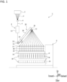
- FIG. 1 depicts a view showing schematically an example of a spun yarn take-up apparatus 1 according to an embodiment of the present invention.
- a spun yarn take-up apparatus 1 includes mainly a spinning unit 2, an oil guide 4, a spun yarn drawing unit 6, a first godet roller 10, a second godet roller 12, an interlacing unit (not shown), and a yarn spooling unit 8.
- an up-and-down direction and a left-and-right direction with respect to the sheet of FIG. 1 will be referred to as an up-and-down direction and a forward-and-backward direction, respectively.
- a direction perpendicular to the sheet of FIG. 1 will be referred to as a left-and-right direction
- a direction toward the viewer (a frontward direction from the sheet) of FIG. 1 will be referred to as a rightward direction.
- a front end side of a bobbin holder 34 is a side at which the operator is expected to operate the spun yarn take-up apparatus 1, and is referred to as a forward side.
- the spun yarn take-up apparatus 1 is configured to draw a plurality of yarns Y, formed by solidifying molten fiber material such as polyester spun continuously from the spinning unit 2 through the use of the spun yarn drawing unit 6, and thereafter take up the plurality of yarns Y through the use of the yarn spooling unit 8 via the first godet roller 10 and the second godet roller 12.
- the spinning unit 2 continuously spins molten fiber material such as polyester downward as a plurality of filaments F.
- the oil guide 4 collects the plurality of filaments F spun from the spinning unit 2 into one yarn Y, and applies an oil to the yarn Y (the plurality of filaments F).
- the plurality of yarns Y having been applied with the oil is fed to the spun yarn drawing unit 6.
- the spun yarn drawing unit 6 is a unit configured to heat and draw the plurality of yarns Y, and is arranged below the spinning unit 2.
- the spun yarn drawing unit 6 includes a thermal insulation box 14 and a plurality of heating rollers (not shown) accommodated inside the thermal insulation box 14.
- the plurality of yarns Y drawn by the spun yarn drawing unit 6 are taken up by the first godet roller 10 and further fed to the yarn spooling unit 8 by the second godet roller 12 arranged downstream the first godet roller 10 in a yarn traveling direction.
- the first godet roller 10 is arranged below the spun yarn drawing unit 6 so that an axial direction thereof corresponds to a left-and-right direction horizontally perpendicular to a spinning direction of the plurality of yarns Y spun from the spinning unit 2. Further, an axial direction of the first godet roller 10 is also horizontally perpendicular to a longitudinal direction of a guide rail 26 to be described later.
- the second godet roller 12 is arranged at a downstream side of the first godet roller 10 in a yarn traveling direction, at a rear upper part of the first godet roller 10, so that an axial direction thereof is parallel to the first godet roller 10. Further, the first godet roller 10 and the second godet roller 12 are supported by a roller up-down mechanism 20.
- the first godet roller 10 is rotated by, e.g., a motor (not shown) as a drive source, but is not limited to this, and may be a free roller rotatable without a motor.
- the roller up-down mechanism 20 includes a bracket 22 supporting rotatably the first godet roller 10, an up-down bracket 24 supporting rotatably the second godet roller 12, a fixed frame (not shown), a guide rail 26, and a motor (not shown).
- the guide rail 26 is a longitudinal member extending from one end toward the other end.
- the guide rail 26 is arranged diagonally with respect to a forward-and-backward direction so that one end (a forward side in FIG. 1 ) of the guide rail 26 is at a bottom and a rear end (a backward side in FIG. 1 ) is at a top. Further, the guide rail 26 is supported by a fixed frame (not shown) extending in a horizontal direction. It is to be noted that the above-described "guide rail 26" corresponds to a "support member" of an embodiment according to the present invention.
- the bracket 22 rotatably supports the first godet roller 10 at one end of the guide rail 26 so that a rotation axis of the first godet roller 10 is perpendicular to an axial direction of a bobbin holder 34 to be described later.
- the up-down bracket 24 rotatably supports the second godet roller 12 so that a rotation axis of the second godet roller 12 is perpendicular to an axial direction of the bobbin holder 34.
- the up-down bracket 24 is movable along a length direction of the guide rail 26 by driving of a motor (not shown).
- the second godet roller 12 is caused to move along a length direction of the guide rail 26 with the movement of the up-down bracket 24.
- the second godet roller 12 When the yarns Y are taken up by the yarn spooling unit 8, the second godet roller 12 is located at a take-up position indicated by a solid line in FIG. 1 , that is, at the other end of the guide rail 26 and above approximately the center in an axial direction of the bobbin holder 34.
- the second godet roller 12 When the yarns Y are wound on the second godet roller 12, the second godet roller 12 is located at a winding position indicated by a broken line in FIG. 1 , that is, at one end of the guide rail 26 and close to the first godet roller 10.
- the second godet roller 12 is movable between the winding position where it is close to the first godet roller 10 and a take-up position where a distance from the first godet roller 10 is greater than the winding position.
- the second godet roller 12 is rotated by, e.g., a motor (not shown) as a drive source, but is not limited to this, and may be a free roller rotatable without a motor.
- the interlacing unit (not shown) is arranged between the first godet roller 10 and the second godet roller 12 so as to entangle a plurality of filaments F including one yarn Y thereby to provide interlacing.
- the yarn spooling unit 8 is arranged below the first godet roller 10 and the second godet roller 12, and is configured to take up a plurality of yarns Y around a plurality of bobbins B to form a package P.
- the yarn spooling unit 8 includes a plurality of fulcrum guides 31, a plurality of traverse guides 32, a turret 33, two bobbin holders 34, e.g., a contact roller 35, and a yarn detection unit 36.
- FIG. 2 depicts a view showing schematically an example of a periphery of a first godet roller 10 and a second godet roller 12 when the second godet roller 12 is arranged at a winding position, viewed from the same direction as that in FIG. 1 .
- FIG. 3 depicts a perspective view showing an example of a periphery of a first godet roller 10 and a second godet roller 12 when the second godet roller 12 is arranged at a winding position, viewed from a forward right side.
- a cover member 50 is arranged at a radially outer side of the first godet roller 10
- a cover member 70 is arranged at a radially outer side of the second godet roller 12. Both the cover member 50 and the cover member 70 correspond to a "winding assisting member" of an embodiment according to the present invention.
- the cover member 50 has a function of ensuring the safety of the operator when winding yarns around the first godet roller 10 and assisting the winding of yarns around the first godet roller 10, and also has a function of preventing a suction gun (see FIGS. 7 and 8 to be described later) from coming into contact with the first godet roller 10.
- the cover member 70 has a function of ensuring the safety of the operator when winding yarns around the second godet roller 12 assisting in winding of yarns around the second godet roller 12, and also has a function of preventing a suction gun from coming into contact with the second godet roller 12.
- winding of yarns around the first godet roller 10 or the second godet roller 12 may be simply referred to as “winding.”
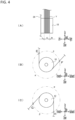
- FIG. 4 depicts explanatory views for explaining regions defined in the present specification of which: a view of (A) shows an example of a first godet roller 10 viewed from a forward side; a view of (B) shows an example of a first godet roller 10 viewed from a right side; and a view of (C) shows an example of a second godet roller 12 viewed from a right side.
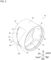
- FIG. 5 depicts a perspective view showing an example of a cover member 50 arranged at a radially outer side of a first godet roller 10 viewed from above at a forward right side.
- FIGS. 5 and 6 depict a view of (A) showing an example of a cover member 50 arranged at a radially outer side of a first godet roller 10 viewed from a forward side, and a view of (B) showing an example of a cover member 50 arranged at a radially outer side of a first godet roller 10 viewed from a backward side. It is to be noted that directions shown in FIGS. 5 and 6 are directions defined when the cover member 50 is arranged at a radially outer side of the first godet roller 10.
- the region C shown in (A) of FIG. 4 is a region where a plurality of yarns Y are wound in an axial direction of the first godet roller 10, and is referred to as a "first axial region C.”
- the region L shown in (A) of FIG. 4 is a region closer to a base end (a guide rail 26 side (left side)) than the first axial region, and is referred to as a "second axial region L.”
- the region R shown in (A) of FIG. 4 is a region closer to a tip end (a right side) than the first axial region, and is referred to as a "third axial region R.”
- first axial region C the region where a plurality of yarns Y are wound in an axial direction of the second godet roller 12
- second axial region L the region closer to the base end (the guide rail 26 side (left side)) than the first axial region
- third axial region R the region closer to a tip end (the right side) than the first axial region
- a portion E shown in (B) of FIG. 4 is a portion (hereinafter, referred to as an "inlet portion E") in which a plurality of yarns Y are introduced to the first godet roller 10.
- a portion F shown in (B) of FIG. 4 is a portion (hereinafter, referred to as an "outlet portion F") in which the plurality of yarns Y are led out from the first godet roller 10.
- the region ⁇ shown in (B) of FIG. 4 is a region from the inlet portion E to the outlet portion F in a direction opposite to a yarn traveling direction (a clockwise direction in (B) of FIG.
- the first circumferential region ⁇ is a region between the inlet portion E and the outlet portion F in a 360-degree circumferential direction of the first godet roller 10, and at a side where the plurality of yarns Y are wound around the first godet roller 10.
- the second circumferential region ⁇ is a region between the inlet portion E and the outlet portion F in a 360-degree circumferential direction of the first godet roller 10, and at a side where the plurality of yarns are not wound around the first godet roller 10.
- the inlet portion E corresponds to an "inlet portion site" of an embodiment according to the present invention
- the outlet portion F corresponds to an "outlet portion site” of an embodiment according to the present invention.
- a portion G shown in (C) of FIG. 4 is a portion (hereinafter, referred to as an "inlet portion G") in which the plurality of yarns Y are introduced to the second godet roller 12.
- a portion H shown in (C) of FIG. 4 is a portion (hereinafter, referred to as an "outlet portion H") in which the plurality of yarns Y are led out from the second godet roller 12.
- a region between the inlet portion G and the outlet portion H at a side where the plurality of yarns Y are wound around the second godet roller 12 is defined as a "first circumferential region ⁇ .”
- a region between the inlet portion G and the outlet portion H at a side where the plurality of yarns are not wound around the second godet roller 12 is defined as a "second circumferential region ⁇ .”
- the inlet portion G also corresponds to an "inlet portion site" of an embodiment according to the present invention
- the outlet portion H also corresponds to an "outlet portion site” of an embodiment according to the present invention.
- the cover member 50 is formed of a cylindrical member in an embodiment according to the present invention, and has a winding guiding portion 52, a fixing portion 54, and a gap 60.
- the winding guiding portion 52 is a portion configured such that a tip of a suction gun (see FIGS. 7 and 8 described below) is brought into contact with the winding guiding portion 52 to move along the winding guiding portion 52 so that yarns can be wound around the first godet roller 10 when winding yarns around the first godet roller 10 using the suction gun.
- the winding guiding portion 52 has a diameter larger than the roller diameter of the first godet roller 10, and is arranged at a radially outer side of the first godet roller 10.
- the winding guiding portion 52 only needs to have a portion corresponding to at least the first circumferential region ⁇ (see FIG. 4 ) in a circumferential direction, and be arranged at least in the third axial region R (see FIG. 4 ) in an axial direction.
- the fixing portion 54 is a portion supported by the guide rail 26 (see FIG. 1 ) at the base end (left end) of the cover member 50.
- This fixing portion 54 has a function of fixing the winding guiding portion 52 and the guide rail 26 and supporting the winding guiding portion 52 on the guide rail 26.
- an axial direction of the cover member 50 made of a cylindrical member is the same as an axial direction of the first godet roller 10.
- the winding guiding portion 52 covers an entire roller surface, in a width direction (left-and-right direction), of the first godet roller 10 in a state where the fixing portion 54 is supported by the guide rail 26, that is, in a state where it is arranged at a radially outer side of the first godet roller 10.
- the winding guiding portion 52 and the fixing portion 54 are made of, e.g ., rigid metal.
- the cover member 50 is a bottomless cylindrical member, and the right end of the first godet roller 10 is opened in a state where the winding guiding portion 52 is arranged at a radially outer side of the first godet roller 10.
- the other end (right end) in an axial direction of the first godet roller 10 is closed in a state where the first godet roller 10 is externally inserted into the winding guiding portion 52, there is a possibility that the first godet roller 10 and the winding guiding portion 52 may disrupt the airflow at a radially outer side of the first godet roller 10, making it difficult to wind yarns around the first godet roller 10.
- the cover member 50 when the cover member 50 is a bottomless cylindrical member, it is possible to suppress the disturbance of the airflow at a radially outer side of the first godet roller 10, and easily wind yarns around the first godet roller 10. It is not necessarily essential, however, that the cover member 50 be a bottomless cylindrical member, and this does not exclude the use of a bottomed cylindrical member as the cover member 50.
- the winding guiding portion 52 of the cover member 50 includes a winding-side extension surface 53 extending from the third axial region R toward the first axial region C (see FIG. 4 ) at a radially outer side of the first godet roller 10. Since the winding guiding portion 52 includes the winding-side extension surface 53, it is possible to increase the strength of the winding guiding portion 52 and maintain the stability when the suction gun (see FIGS. 7 and 8 described below) is caused to move with a tip thereof pressed against the winding guiding portion 52.
- the winding-side extension surface 53 has a side surface 53a facing toward the guide rail 26 (the left side in FIG. 5 ). A gap 60 is formed between this side surface 53a and a side surface 58a of a fixed-side extension surface 58 to be described later.
- the above-described “winding-side extension surface 53" corresponds to an "other-side extension surface” of an embodiment according to the present invention. Further, the above-described “side surface 53a” corresponds to a "side portion" of an embodiment according to the present invention.
- the fixing portion 54 of the cover member 50 includes at least a connecting portion 55 connecting between the guide rail 26 and the winding guiding portion 52, and a specific fixing portion 56 supported by the guide rail 26.
- the connecting portion 55 is arranged in the second circumferential region ⁇ . Therefore, the connecting portion 55 can be prevented from coming into contact with the plurality of yarns Y.
- the specific fixing portion 56 may be provided in the first circumferential region ⁇ without being provided in the second circumferential region ⁇ , or may be provided in the second circumferential region ⁇ without being provided in the first circumferential region ⁇ , or may be provided in both the first circumferential region ⁇ and the second circumferential region ⁇ .
- the fixing portion 54 is provided in both the first circumferential region ⁇ and the second circumferential region ⁇ .
- the fixing portion 54 includes a fixed-side extension surface 58 extending from the specific fixing portion 56 toward the first axial region (see FIG. 4 ) at a radially outer side of the first godet roller 10. Since the fixing portion 54 includes the fixed-side extension surface 58, the fixing portion 54 can be stably fixed to the guide rail 26.
- the fixed-side extension surface 58 has a side surface 58a facing the side (the right in FIG. 5 ) opposite to the guide rail 26.
- the above-described "fixed-side extension surface 58" corresponds to a "one-side extension surface" of an embodiment according to the present invention.
- the winding guiding portion 52 include the winding-side extension surface 53 and that the fixing portion 54 include the fixed-side extension surface 58.
- the winding guiding portion 52 includes the winding-side extension surface 53 and the fixing portion 54 does not include the fixed-side extension surface 58
- a mode in which the winding guiding portion 52 does not include the winding-side extension surface 53 and the fixing portion 54 includes the fixed-side extension surface 58 may be used.
- winding-side extension surface 53 and the fixed-side extension surface 58 are in the same plane, the winding-side extension surface 53 and the fixed-side extension surface 58 are not necessarily in the same plane. For example, there may be a step between the winding-side extension surface 53 and the fixed-side extension surface 58.
- the gap 60 is formed along a circumferential direction between the winding-side extension surface 53 and the fixed-side extension surface 58 in an axial direction of the first godet roller 10, that is, at a side closer to the first axial region C from the winding guiding portion 52.
- This gap 60 includes a first gap 62 formed at the inlet portion E (see FIG. 4 ) through which a plurality of yarns Y are introduced to the first godet roller 10, a second gap 64 formed in the outlet portion F (see FIG. 4 ) through which the plurality of yarns Y are led out from the first godet roller 10, and a third gap 66 formed between the first gap 62 and the second gap 64 downstream the first gap 62 in a yarn traveling direction of the plurality of yarns.
- the third gap 66 is formed continuously from the first gap 62 as the inlet portion E to the second gap 64 as the outlet portion F over at least the entire region of the first circumferential region ⁇ (see FIG. 4 ).
- the first gap 62 is an opening through which a plurality of yarns Y are passed in order to wind a plurality of yarns around the first godet roller 10, and is provided along a circumferential direction of the winding guiding portion 52 in an inverted triangular shape having an apex portion 63 at the bottom. In this way, by forming the first gap 62 into an inverted triangular shape, it is possible to increase the opening of the inlet portion E of a plurality of yarns to the first godet roller 10, and prevent the yarns Y from coming into contact with the cover member 50 when winding yarns around the first godet roller 10.
- the size (opening width) of the apex portion 63 at the bottom of the first gap 62 in an axial direction (horizontal left-and-right direction) is smaller than a tip of the suction gun 80 (see FIGS. 7 and 8 described below). Therefore, a tip of the suction gun 80 can be prevented from coming into contact with a roller surface of the first godet roller 10.
- the second gap 64 is an opening for leading out a plurality of yarns from the first godet roller 10, and is provided along a circumferential direction in a rectangular shape. It is preferable that the opening width of the second gap 64 in an axial direction (horizontal left-and-right direction) is larger than an opening width at the apex portion 63 of the first gap 62, and is larger than a yarn traveling width (size in a direction perpendicular to a yarn traveling direction (that is, a horizontal left-and-right direction)) of the plurality of yarns Y. By doing so, when the yarn Y separates from a roller surface of the first godet roller 10, the separated yarn Y can be fed to the second godet roller 12 without coming into any contact with the cover member 50.
- the third gap 66 is an opening having an opening width smaller than that of both the first gap 62 and the second gap 64, and having a slit shape along a circumferential direction of the winding guiding portion 52 so that the first gap 62 and the second gap 64 are continuous.
- the opening width of the third gap 66 in an axial direction is smaller than that at a tip of the suction gun 80 (see FIGS. 7 and 8 described below). Therefore, even if the suction gun 80 is caused to move along the outer circumference of the winding guiding portion 52, a tip of the suction gun 80 can be prevented from coming into contact with the first godet roller 10.
- the third gap 66 is provided so that yarns can be wound around the first godet roller 10 simply by causing the suction gun 80 to move within the range of the third gap 66 provided in a circumferential direction of the winding guiding portion 52. By doing so, it is possible to more reliably prevent a tip of the suction gun 80 from coming into contact with the first godet roller 10 when yarns are wound around the first godet roller 10.
- FIG. 7 depicts a view showing a state of, when winding operation of yarns around a first godet roller 10 is started, an example of a periphery of the first godet roller 10 viewed from a forward side.
- FIG. 7 for convenience, only the cover member 50, the first godet roller 10, and the suction gun 80 are shown, and the guide rail 26 and the like are not shown.
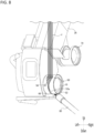
- FIG. 8 depicts a perspective view showing a state of, when yarns are being wound around a first godet roller 10, an example of a periphery of the first godet roller 10 and a second godet roller 12 viewed from a forward right side.
- the winding yarns around the first godet roller 10 is performed by causing the suction gun 80 to move closer to the winding guiding portion 52 from the third axial region R side below the first gap 62. Then, as shown in FIG. 8 , the suction gun 80 is caused to move counterclockwise along a circumferential direction while being brought into contact with the outer circumference of the winding guiding portion 52 and yarns are wound around the first godet roller 10 so that the winding angle around the first godet roller 10 is less than 360 degrees.
- the suction gun 80 by causing the suction gun 80 to move along a circumferential direction while being brought into contact with the outer circumference of the winding guiding portion 52, a plurality of yarns Y can be wound around the first godet roller 10.
- the range in which the suction gun 80 is caused to move along a circumferential direction while being brought into contact with the outer circumference of the winding guiding portion 52 is approximately the range in which the third gap 66 is provided.
- the cover member 50 by employing a cylindrical member in which the winding guiding portion 52 and the fixing portion 54 are integrated as the cover member 50, the robustness of the cover member 50 can be ensured. Therefore, since yarns can be wound around the first godet rollers 10 by passing a plurality of yarns Y through the gap 60 provided in the cylindrical member while causing the suction gun to move along the outer circumference of the cylindrical member, winding yarns around the first godet roller 10 can be easily performed.
- the winding guiding portion 52 has a perfect circular arc shape when viewed from the right side shown in FIG. 8 , for example. This is because yarns can be easily wound around the first godet roller 10, that is, the suction gun 80 can be easily caused to move along a circumferential direction while being brought into contact with the outer circumference of the winding guiding portion 52.
- the shape of the winding guiding portion 52 when viewed from the right side is preferably a perfect circular arc shape, but it is sufficient as long as it does not have at least a corner, and for example, it may be an elliptical arc shape.
- the winding guiding portion 52 only needs to exist at least in the first circumferential region ⁇ , and does not need to exist in the second circumferential region ⁇ .
- FIG. 9 depicts a perspective view of an example of a cover member 70 arranged at a radially outer side of a second godet roller 12 when viewed from above at a forward right side. It is to be noted that a direction shown in FIG. 9 is a direction when the cover member 70 is arranged at a radially outer side of the second godet roller 12.
- the cover member 70 has a winding guiding portion 72 and a fixing portion 74.
- the winding guiding portion 72 has a side surface 72a facing the guide rail 26 (left side shown in FIG. 9 ), and the fixing portion 74 has a side surface 74a facing the side (the right side shown in FIG. 9 ) opposite to the guide rail 26.
- a gap 76 is formed between the side surface 72a of the winding guiding portion 72 and the side surface 74a of the fixing portion 74.
- the above-described "side surface 72a" also corresponds to a "side portion" of an embodiment according to the present invention.
- the winding guiding portion 72 is a portion configured such that a tip of a suction gun (see FIGS. 7 and 8 described below) is brought into contact with the winding guiding portion 72 to move along the winding guiding portion 72 so that yarns can be wound around the second godet roller 12 when winding yarns around the second godet roller 12 using the suction gun.
- the winding guiding portion 72 has a diameter larger than the roller diameter of the second godet roller 12 and is arranged at a radially outer side of the second godet roller 12 at least in the third axial region R.
- the winding guiding portion 72 only needs to have at least a first circumferential region ⁇ (see FIG. 4 ) in a circumferential direction, and at least a third axial region R (see FIG. 4 ) in an axial direction.
- the fixing portion 74 is a portion supported by the guide rail 26 (see FIG. 1 ) at the base end (left end) of the cover member 70.
- This fixing portion 74 has a function of fixing the winding guiding portion 72 and the guide rail 26 and supporting the winding guiding portion 72 on the guide rail 26.
- an axial direction of the cover member 70 is the same as an axial direction of the second godet roller 12.
- the winding guiding portion 72 covers an entire roller surface, in a width direction (left-and-right direction), of the second godet roller 12 in a state where the fixing portion 74 is supported by the guide rail 26, that is, in a state where it is arranged at a radially outer side of the second godet roller 12.
- the winding guiding portion 72 and the fixing portion 74 are made of rigid metal, for example.
- the gap 76 is formed along a circumferential direction between the winding guiding portion 72 and the fixing portion 74, that is, at a side closer to the first axial region C from the winding guiding portion 72.
- the opening width of the gap 76 is preferably larger than a yarn traveling width of the plurality of yarns Y. By doing so, the yarns Y fed to the second godet roller 12 can be brought into contact with a roller surface of the second godet roller 12 without coming into any contact with the cover member 70.
- the gap 76 is formed continuously from the inlet portion G to the outlet portion H over at least the entire region of the first circumferential region ⁇ (see FIG. 4 ).
- the distance to the second godet roller 12 from the operator is farther than that of the first godet roller 10, it is more difficult to wind yarns around the second godet roller 12 than winding yarns around the first godet roller 10.
- the opening width of the gap 76 larger than a yarn traveling width of the plurality of yarns Y, it is possible to easily wind the plurality of yarns around the second godet roller 12.
- the suction gun 80 can be prevented from coming into contact with a roller surface of the second godet roller 12.
- FIG. 10 depicts a perspective view showing a state of, when winding operation of yarns around a second godet roller 10 is started, an example of a periphery of a first godet roller 10 and the second godet roller 12 viewed from a forward right side.
- the second godet roller 12 is placed at the winding position (the portion indicated by the broken line in FIG. 1 ).
- the winding yarns around the second godet roller 12 is performed by bringing the suction gun 80 closer to the winding guiding portion 72 from the third axial region R side below the gap 76. Then, the suction gun 80 is caused to move clockwise along a circumferential direction while being brought into contact with the outer circumference of the winding guiding portion 72 and yarns are wound around the second godet roller 12 so that the winding angle around the second godet roller 12 is less than 360 degrees.
- the suction gun 80 to move along a circumferential direction while being brought into contact with the outer circumference of the winding guiding portion 72, the plurality of yarns Y pass through the gap 76 and come into contact with a roller surface of the second godet roller 12, and yarns can be wound around the second godet roller 12.
- the second godet roller 12 is caused to move along a length direction of the guide rail 26 toward the take-up position (the portion indicated by the solid line in FIG. 1 ).
- the winding guiding portion 72 has a perfect circular arc shape when viewed from the right side shown in FIG. 10 , for example. This is because yarns can be easily wound around the second godet roller 12, that is, the suction gun 80 can be easily caused to move along a circumferential direction while being brought into contact with the outer circumference of the winding guiding portion 72.
- the shape of the winding guiding portion 72 when viewed from the right side is preferably a perfect circular arc shape, but it is sufficient as long as it does not have at least a corner, and for example, it may be an elliptical arc shape. Further, the winding guiding portion 72 only needs to exist at least in the first circumferential region ⁇ , and does not need to exist in the second circumferential region ⁇ .
- the cover member 50 is provided at a radially outer side of the first godet roller 10, it is possible to prevent the operator from coming into contact with the first godet roller 10, assist in winding yarns around the first godet roller 10, and improve safety during winding.
- the first godet roller 10 is rotating, it is dangerous for the operator, but by providing the cover member 50 at a radially outer side of the first godet roller 10, the safety of the operator can be ensured.
- the cover member 70 is provided at a radially outer side of the second godet roller 12, it is possible to prevent the operator from coming into contact with the second godet roller 12, assist in winding yarns around the second godet roller 12, and improve the safety during winding.
- the second godet roller 12 is rotating, it is dangerous for the operator, but by providing the cover member 70 at a radially outer side of the second godet roller 12, the safety of the operator can be ensured.
- the cover member 50 is configured as a bottomless cylindrical member whose right end in an axial direction (horizontal left-and-right direction) is open in a state of being arranged at a radially outer side of the first godet roller 10, it is possible to suppress the disturbance of the airflow at a radially outer side of the first godet roller 10, and easily wind yarns around the first godet roller 10.
- the cover member 50 has the inverted triangular first gap 62 having the apex portion 63 at the bottom in the inlet portion E through which a plurality of yarns Y are introduced to the first godet roller 10.
- the opening width of the apex portion 63 is smaller than a tip of the suction gun 80.
- the opening width of the third gap 66 is smaller than a tip of the suction gun 80. Therefore, it is possible to prevent a tip of the suction gun 80 from coming into contact with a roller surface of the first godet roller 10 when yarns are wound around the first godet roller 10.
- the cover member 50 has the rectangular second gap 64 in the outlet portion F through which the plurality of yarns Y are led out from the first godet roller 10. Since the opening width of the second gap 64 is larger than the opening width at the lower apex portion 63 of the first gap 62, when yarns Y separate from a roller surface of the first godet roller 10, the separated yarns Y can be prevented from coming into contact with the cover member 50.
- the cover member 50 has the slit-shaped third gap 66 between the first gap 62 and the second gap 64, and has an opening width smaller than a tip of the suction gun. Therefore, it becomes possible to wind yarns around the first godet roller 10 with a simple operation while ensuring the operator's safety over the entire range from the start to the end of the winding yarns around the first godet roller 10. Further, it is possible to prevent occurrence of scratches that may be caused by the suction gun 80 coming into contact with the godet roller 10.
- the cover member 50 is provided at a radially outer side of the first godet roller 10
- the cover member 70 is provided at a radially outer side of the second godet roller 12, but the invention is not limited to this. That is, a cover member (the cover member 50 or the cover member 70) may be provided at a radially outer side of at least one of the first godet roller 10 and the second godet roller 12.
- the cover member 50A can have a function of assisting the winding of yarns around the first godet roller 10.
- the cover member 70A can have a function of assisting the winding of yarns around the second godet roller 12. That is, both the cover member 50A and the cover member 70A can be said to correspond to a "winding assisting member" of an embodiment according to the present invention.
- the cover member 50 is a cylindrical member, it is not necessarily essential that the cover member 50 be a cylindrical member if it is possible to wind yarns around the first godet roller 10 with a simple operation while ensuring the safety of the operator.
- the cover member 50 may be configured with a ring-shaped winding guiding portion and a fixing portion that fixes the ring-shaped winding guiding portion and the guide rail 26. The same applies to the cover member 70.
- FIG. 11 depicts a perspective view of a modified example of a periphery of a first godet roller 10 and a second godet roller 12 when the second godet roller 12 is arranged at a winding position.
- a cover member 50A is provided in place of the cover member 50
- a cover member 70A is provided in place of the cover member 70.
- the cover member 50A includes a ring-shaped winding guiding portion 52A having a diameter larger than the roller diameter of the first godet roller 10, and a connecting fixing portion 54A.
- the winding guiding portion 52A has a side surface 52Aa facing the guide rail 26 (the left side in FIG. 9 ), and forms a space 60A between the side surface 52Aa and the guide rail 26.
- the space 60A is formed closer to the first axial region C than the winding guiding portion 52A.
- the above-described side surface 52Aa also corresponds to a "side portion" of an embodiment according to the present invention.
- the connecting fixing portion 54A is a rod-shaped member extending leftward from the winding guiding portion 52A, and is supported by the guide rail 26 at the left end.
- the connecting fixing portion 54A has a function of connecting the winding guiding portion 52A and the guide rail 26, and a function of being supported by the guide rail 26.
- the connecting fixing portion 54A is arranged in the second circumferential region ⁇ (see (B) of FIG. 4 ) in an axial direction. By doing so, it is possible to prevent the connecting fixing portion 54A from coming into contact with the plurality of yarns Y.
- the cover member 50A has the connecting fixing portion 54A that has both the function of connecting the winding guiding portion 52A and the guide rail 26 and the function of being supported by the guide rail 26.
- the cover member 50A may have a connecting portion that has a function of connecting the winding guiding portion 52A and the guide rail 26, and a specific fixing portion that has a function of being supported by the guide rail 26.
- the connecting portion can be prevented from coming into contact with the plurality of yarns Y if it is arranged at least in the second circumferential region ⁇ in the first axial region C. That is, in the second axial region L and the third axial region R, the connecting portion may be arranged in the first circumferential region ⁇ (see FIG. 4 ).
- the specific fixing portion may be arranged in either the first circumferential region ⁇ or the second circumferential region ⁇ .
- the cover member 70A includes a ring-shaped winding guiding portion 72A having a diameter larger than the roller diameter of the second godet roller 12, and a connecting fixing portion 74A.
- the winding guiding portion 72A has a side surface 72Aa facing the guide rail 26 (the left side in FIG. 9 ), and forms a space 76A between the side surface 72Aa and the guide rail 26.
- the space 76A is formed closer to the first axial region C than the winding guiding portion 72A.
- the above-described side surface 72Aa also corresponds to a "side portion" of an embodiment according to the present invention.
- the connecting fixing portion 74A is a rod-shaped member extending leftward from the winding guiding portion 72A, and is supported by the guide rail 26 at the left end.
- the connecting fixing portion 74A has a function of connecting the winding guiding portion 72A and the guide rail 26, and a function of being supported by the guide rail 26.
- the connecting fixing portion 74A is arranged in the second circumferential region ⁇ (see FIG. 4C ) in an axial direction. By doing so, it is possible to prevent the connecting fixing portion 54A from coming into contact with the plurality of yarns Y.
- the cover member 70A also has the connecting fixing portion 74A that has both the function of connecting the winding guiding portion 72A and the guide rail 26 and the function of being supported by the guide rail 26.
- the cover member 70A may include a connecting portion that has a function of connecting the winding guiding portion 72A and the guide rail 26, and a specific fixing portion that has a function of being supported by the guide rail 26.
- the connecting portion can be prevented from coming into contact with the plurality of yarns Y if it is arranged at least in the second circumferential region ⁇ in the first axial region C.
- the connecting portion may be arranged in the first circumferential region ⁇ (see FIG. 4 ). Further, the specific fixing portion may be arranged in either the first circumferential region ⁇ or the second circumferential region ⁇ .
- winding yarns around the first godet roller 10 can be performed by a simple operation of causing the suction gun 80 to move along a circumferential direction while being brought into contact with the outer circumference of the winding guiding portion 52A, and damage to the first godet roller 10 can be prevented.
- the second godet roller 12 even if the cover member 70A is provided at a radially outer side of the second godet roller 12 in place of the cover member 70, in the same manner as in the case where the cover member 70 is provided, it is possible to prevent the operator from coming into contact with the second godet roller 12, assist in winding yarns around the second godet roller 12, and improve the safety during winding. Further, winding yarns around the second godet roller 12 can be performed by a simple operation of causing the suction gun 80 to move along a circumferential direction while being brought into contact with the outer circumference of the winding guiding portion 72A, and damage to the second godet roller 12 can be prevented.
- the cover member 50A has the ring-shaped winding guiding portion 52A. That is, although the cover member 50A has the winding guiding portion 52A in the entire circumferential region, the present invention is not limited thereto.
- the winding guiding portion may be, e.g., a ring-shaped portion with a cut-out portion. If a portion of the winding guiding portion at least in the first circumferential region ⁇ in a circumferential direction is provided in the third axial region R (see FIG. 4 ), a plurality of yarns can be wound around the godet roller without the suction gun 80 (see FIGS. 7 and 8 ) coming into any contact with the godet roller.
- the cover member 70A has the ring-shaped winding guiding portion 72A. That is, although the cover member 70A has the winding guiding portion 72A in the entire circumferential region, the present invention is not limited thereto.
- the winding guiding portion may be, e.g., a ring-shaped portion with a cut-out portion. If a portion of the winding guiding portion at least in the first circumferential region ⁇ in a circumferential direction is provided in the third axial region R (see FIG. 4 ), a plurality of yarns can be wound around the godet roller without the suction gun 80 (see FIGS. 7 and 8 ) coming into any contact with the godet roller.
- both the winding guiding portion 52A and the winding guiding portion 72A are set within the range necessary for winding yarns Y around the godet rollers 10 and 12 using at least the suction gun 80 (see FIGS. 7 and 8 ).
- the winding guiding portion 52A and the winding guiding portion 72A similarly to the winding guiding portion 52 and the winding guiding portion 72, have a perfect circular arc shape when viewed from the right side shown in FIG. 11 , for example.
- the present invention is not limited to this, and the winding guiding portion 52A and the winding guiding portion 72A only need to have at least no corners when viewed from the right side shown in FIG. 11 , e.g ., may have an elliptical arc shape.
- both the cover member 50 and the cover member 70 are changed to the cover member 50A and the cover member 70A, respectively.
- the present invention is not limited to this, and only one of the cover member 50 and the cover member 70 may be changed to the cover member 50A or the cover member 70A.
- the side surface 53a of the above-described winding guiding portion (more specifically, the winding-side extension surface 53), the side surface 58a of the fixing portion 54 (more specifically, the fixed-side extension surface 58), the side surface 72a of the winding guiding portion 72, the side surface 74a of the fixing portion 74, the side surface 52Aa of the winding guiding portion 52A, and the side surface 72Aa of the winding guiding portion 72A are not limited to being surfaces, and the side surfaces may be any side portion that forms a gap or a space through which yarns can be wound around the godet rollers 10 and 12.
- the spun yarn take-up apparatus 1 including the spun yarn drawing unit 6 has been described, but it is not necessarily essential that the spun yarn take-up apparatus 1 includes the spun yarn drawing unit 6. That is, the plurality of yarns Y produced by the spun yarn take-up apparatus 1 are not limited to fully drawn yarns (FDY), but may also be partially drawn yarns (POY) or bi-shrinkage yarns (BSY) in which FDY and POY are mixed. The same applies to the above-described modified examples.
Landscapes
- Spinning Methods And Devices For Manufacturing Artificial Fibers (AREA)
Abstract
Description
- The present invention relates to a spun yarn take-up apparatus for taking up yarns spun from a spinning unit.
-
Patent Document 1, e.g., discloses a spun yarn take-up apparatus including a godet roller driven rotationally by a motor and a spooling unit arranged below the godet roller. The godet roller is configured to take up a plurality of yarns spun from a spinning unit so as to feed the plurality of yarns downstream in a yarn traveling direction. The spooling unit is configured to, when starting taking-up operation, take up the plurality of yarns fed from the godet roller onto a bobbin thereby to form a package. - Before starting taking-up operation in the spooling unit, winding operation of winding yarns around a godet roller is performed. The winding operation is performed by an operator expected to, while suctioning to hold a plurality of yarns with a suction gun, set to wind such yarns around a godet roller or the like.
- (Prior Art Documents)
- Patent Document 1:
Japanese Patent Application Publication No. 2021-050440 - Incidentally, the suction gun is not only heavy for the operator but also has a suction force acting on a yarn to attract the yarn. It is therefore difficult to wind yarns without bringing such a suction gun into any contact with the godet roller, and there is a probability that, if the suction gun comes into contact with the godet roller during winding, a surface of the godet roller would be damaged by the suction gun. Further, it is difficult to say that the winding operation is necessarily safe.
- The present invention has been made in view of the above-described technical problems, and an objective thereof is to provide a spun yarn take-up apparatus capable of facilitating winding operation of yarns while preventing damage to a godet roller so as to improve safety.
- A first aspect of the present invention is a spun yarn take-up apparatus comprising:
- a support member;
- a godet roller having one end, supported by the support member, whose axial direction is perpendicular to a direction in which a plurality of yarns are spun from a spinning unit, the godet roller configured to be wound around with the plurality of yarns at a winding angle less than 360 degrees so as to feed the wound plurality of yarns downstream in a yarn traveling direction; and
- a winding assisting member for assisting in winding the plurality of yarns around the godet roller,
- wherein the winding assisting member includes at least
- a winding guiding portion arranged at a radially outer side of a roller surface of the godet roller, and
- a fixing portion for fixing the winding guiding portion to the support member, and
- wherein the winding guiding portion and the fixing portion are configured such that,
- where, among regions in an axial direction of the godet roller, a region for the plurality of yarns to be wound is defined as a first axial region, a region closer to the one end than the first axial region is defined as a second axial region, and a region closer to the other end opposite to the one end than the first axial region is defined as a third axial region, and
- where, among regions in a circumferential direction of the godet roller, a region for the plurality of yarns to be wound around the godet roller between an inlet portion site for the plurality of yarns to be introduced to the godet roller and an outlet portion site for the plurality of yarns to be led out from the godet roller is defined as a first circumferential region, and a region for the plurality of yarns not to be wound is defined as a second circumferential region,
- at least a portion of the first circumferential region in a circumferential direction of the winding guiding portion has a side portion facing the support member and is positioned at least in the third axial region, and
- at least a portion of the first axial region in an axial direction of the fixing portion is positioned in the second circumferential region.
- According to the above-described first aspect of the spun yarn take-up apparatus, by pressing a tip of a suction gun against the winding guiding portion from the third axial region and thereafter causing the suction gun to move along the winding guiding portion, a plurality of yarns can be introduced and wound around the godet roller while preventing the suction gun from coming into contact with the godet roller. Further, since the winding guiding portion has a side portion facing the support member, there is nothing to obstruct winding operation of yarns between the winding guiding portion and the support member, and a portion of the first axial region in an axial direction of the fixing portion is positioned in the second circumferential region. By causing the suction gun to move along the winding guiding portion, therefore, it is possible to facilitate winding operation of yarns around the godet roller without bringing the suction gun into any contact with the fixing portion, and thereby, a spun yarn take-up apparatus excellent in workability and safety can be provided.
- It is to be noted that, if at least a portion of the first circumferential region in a circumferential direction of the winding guiding portion is positioned in the third axial region, a plurality of yarns can be wound around the godet roller without bringing the suction gun into any contact with the godet roller. A portion of the second circumferential region of the winding guiding portion may, however, be positioned in the third axial region.
- Further, if at least a portion of the first axial region in an axial direction of the fixing portion is positioned in the second circumferential region, the fixing portion can be prevented from coming into contact with a plurality of yarns. A portion of the second region and a portion of the third region in an axial direction of the fixing portion may therefore be positioned in either the first circumferential region or the second circumferential region.
- A second aspect of the present invention is the spun yarn take-up apparatus, wherein
- the winding guiding portion includes an other-side extension surface extending from the third axial region toward the first axial region at a radially outer side of a roller surface of the godet roller, and
- the side portion is a side portion of the other-side extension surface, and is formed with a gap through which the plurality of yarns are introduced to the godet roller.
- According to the above-described second aspect of the spun yarn take-up apparatus, the winding guiding portion includes the other-side extension surface, and therefore, the strength of the winding guiding portion can be increased, and stability can be maintained when the tip of the suction gun pressed against the winding guiding portion is caused to move.
- It is to be noted that the gap may be formed between the side portion of the other-side extension surface and the support member, or when there is another member between the other-side extension surface and the support member, the gap may be formed between the side portion of the other-side extension surface and said another member.
- A third aspect of the present invention is the spun yarn take-up apparatus, wherein
- the fixing portion includes a one-side extension surface extending from the second axial region toward the first axial region at a radially outer side of a roller surface of the godet roller,
- the one-side extension surface has a side portion at a side thereof opposite to the support member, and
- According to the above-described third aspect of the spun yarn take-up apparatus, the fixing portion includes the one-side extension surface, and therefore, the fixing portion can be stably fixed to the support member.
- It is to be noted that the gap may be formed between the side portion of the one-side extension surface and a winding inlet portion, or when there is another member between the one-side extension surface and the winding inlet portion, the gap may be formed between the side portion of the one-side extension surface and said another member. Further, when the winding guiding portion includes the other-side extension surface, a gap may be formed between the side portion of the one-side extension surface and the side portion of the other-side extension surface.
- Further, when the winding guiding portion includes the other-side extension surface and the fixing portion includes the one-side extension surface, it is preferred that the one-side extension surface and the other-side extension surface are in the same plane. It is not necessarily essential, however, that the one-side extension surface and the other-side extension surface be in the same plane, and there may be a step, e.g., between the one-side extension surface and the other-side extension surface.
- A fourth aspect of the present invention is the spun yarn take-up apparatus, wherein
the winding guiding portion and the fixing portion are formed in an annular shape, and the annular fixing portion and the annular winding guiding portion are formed in a cylindrical member arranged at a radially outer side of the godet roller. - According to the above-described fourth aspect of the spun yarn take-up apparatus, the winding guiding portion and the fixing portion are integrated so that they are formed in a cylindrical member, and therefore, the robustness of the winding guiding portion and the fixing portion can be ensured. Further, by causing the suction gun to move along an outer circumference of the cylindrical member while the robustness of the winding guiding portion and the fixing portion being ensured, a plurality of yarns can be wound around the godet roller from the gap without bringing the suction gun into any contact with the godet roller.
- A fifth aspect of the present invention is the spun yarn take-up apparatus, wherein
the fixing portion and the winding guiding portion are formed in a bottomless cylindrical member having an open end in the third axial region in a state of being arranged at a radially outer side of the godet roller. - According to the above-described fifth aspect of the spun yarn take-up apparatus, the fixing portion and the winding guiding portion are formed in a bottomless cylindrical member having the end in the third axial region is opened, and therefore, winding operation of yarns around the godet roller can be easily performed. That is, when the end in the third axial region of the cylindrical member in a state of being arranged at a radially outer side of the godet roller is closed, airflow between the godet roller and the cylindrical member, i.e., at a radially outer side of a roller surface of the godet roller is disturbed, which may result in difficulty in winding yarns around the godet roller. In this regard, by making the cylindrical member having an open end in the third axial region, it is possible to suppress such disturbance of airflow at a radially outer side of a roller surface of the godet roller, and easily wind yarns around the godet roller.
- A sixth aspect of the present invention is the spun yarn take-up apparatus, wherein
the gap has a first gap formed at a portion through which the plurality of yarns are introduced to the godet roller and a second gap formed downstream from the first gap in a yarn traveling direction of the plurality of yarns so as to be smaller in size in an axial direction than the first gap. - According to the above-described sixth aspect of the spun yarn take-up apparatus, it is easy to introduce a plurality of yarns to the godet roller from the first gap, and the second gap smaller in size in an axial direction than the first gap, and therefore, after yarns having been introduced, the suction gun can be prevented from coming into contact with the godet roller.
- A seventh aspect of the present invention is the spun yarn take-up apparatus, wherein
the godet roller includes at least: - a first godet roller configured to feed the plurality of yarns spun from the spinning unit downstream in a yarn traveling direction; and
- a second godet roller arranged downstream from the first godet roller in a yarn traveling direction so as to feed the plurality of yarns fed from the first godet roller downstream in a yarn traveling direction, and wherein
- the support member includes a guide rail supporting the first godet roller and the second godet roller,
- at a winding position where the first godet roller and the second godet roller are close to each other, winding operation is performed in the order of the first godet roller and the second godet roller,
- when the plurality of yarns having been wound, the second godet roller is caused to move along the support member to a take-up position away from the first godet roller, and
- the winding assisting member is arranged for at least one of the first godet roller and the second godet roller.
- According to the above-described seventh aspect of the spun yarn take-up apparatus, the winding assisting member may be arranged only for the first godet roller out of the first godet roller and the second godet roller, or may be arranged only for the second godet roller, or may be arranged for both the first godet roller and the second godet roller. In either case, similar effects to those of the first to sixth aspects can be achieved.
- The spun yarn take-up apparatus according to the present invention does not necessarily include all the first to seventh aspects. The spun yarn take-up apparatus according to the present invention may include only the first aspect. Alternatively, the spun yarn take-up apparatus according to the present invention may include the first aspect combined arbitrarily with any of the second to seventh aspects to such an extent that consistency can be achieved.
- According to the present invention, it is possible to provide a spun yarn take-up apparatus capable of facilitating winding operation of yarns while preventing damage to a godet roller so as to improve safety.
-
-
FIG. 1 depicts a view showing schematically an example of a spun yarn take-up apparatus according to an embodiment of the present invention. -
FIG. 2 depicts a view showing schematically an example of a periphery of a first godet roller and a second godet roller when the second godet roller is arranged at a winding position, viewed from the same direction as that inFIG. 1 . -
FIG. 3 depicts a perspective view showing an example of a periphery of a first godet roller and a second godet roller when the second godet roller is arranged at a winding position, viewed from a forward right side. -
FIG. 4 depicts explanatory views for explaining regions defined in the present specification of which: a view of (A) shows an example of a first godet roller viewed from a forward side; a view of (B) shows an example of a first godet roller viewed from a right side; and a view of (C) shows an example of a second godet roller viewed from a right side. -
FIG. 5 depicts a perspective view showing an example of a cover member arranged at a radially outer side of a first godet roller viewed from above at a forward right side. -
FIG. 6 depicts a view of (A) showing an example of a cover member arranged at a radially outer side of a first godet roller viewed from a forward side, and a view of (B) showing an example of a cover member arranged at a radially outer side of a first godet roller viewed from a backward side. -
FIG. 7 depicts a view showing a state of, when winding operation of yarns around a first godet roller is started, an example of a periphery of the first godet roller viewed from a forward side. -
FIG. 8 depicts a perspective view showing a state of, when yarns are being wound around a first godet roller, an example of a periphery of the first godet roller and a second godet roller viewed from a forward right side. -
FIG. 9 depicts a perspective view of an example of a cover member arranged at a radially outer side of a second godet roller when viewed from above at a forward right side. -
FIG. 10 depicts a perspective view showing a state of, when winding operation of yarns around a second godet roller is started, an example of a periphery of a first godet roller and the second godet roller viewed from a forward right side. -
FIG. 11 depicts a perspective view of a modified example of a periphery of a first godet roller and a second godet roller when the second godet roller is arranged at a winding position. - Hereinafter, a preferred embodiment of the present invention (hereinafter, referred to as an "embodiment of the present invention") will be described with reference to the drawings.
FIG. 1 depicts a view showing schematically an example of a spun yarn take-upapparatus 1 according to an embodiment of the present invention. - As shown in
FIG. 1 , a spun yarn take-upapparatus 1 includes mainly aspinning unit 2, anoil guide 4, a spunyarn drawing unit 6, afirst godet roller 10, asecond godet roller 12, an interlacing unit (not shown), and ayarn spooling unit 8. - In the present specification, an up-and-down direction and a left-and-right direction with respect to the sheet of
FIG. 1 will be referred to as an up-and-down direction and a forward-and-backward direction, respectively. Further, a direction perpendicular to the sheet ofFIG. 1 will be referred to as a left-and-right direction, and a direction toward the viewer (a frontward direction from the sheet) ofFIG. 1 will be referred to as a rightward direction. It is to be noted that a front end side of abobbin holder 34, to be described later, is a side at which the operator is expected to operate the spun yarn take-upapparatus 1, and is referred to as a forward side. - The spun yarn take-up
apparatus 1 is configured to draw a plurality of yarns Y, formed by solidifying molten fiber material such as polyester spun continuously from thespinning unit 2 through the use of the spunyarn drawing unit 6, and thereafter take up the plurality of yarns Y through the use of theyarn spooling unit 8 via thefirst godet roller 10 and thesecond godet roller 12. - The
spinning unit 2 continuously spins molten fiber material such as polyester downward as a plurality of filaments F. Theoil guide 4 collects the plurality of filaments F spun from thespinning unit 2 into one yarn Y, and applies an oil to the yarn Y (the plurality of filaments F). The plurality of yarns Y having been applied with the oil is fed to the spunyarn drawing unit 6. - The spun
yarn drawing unit 6 is a unit configured to heat and draw the plurality of yarns Y, and is arranged below thespinning unit 2. The spunyarn drawing unit 6 includes athermal insulation box 14 and a plurality of heating rollers (not shown) accommodated inside thethermal insulation box 14. - The plurality of yarns Y drawn by the spun
yarn drawing unit 6 are taken up by thefirst godet roller 10 and further fed to theyarn spooling unit 8 by thesecond godet roller 12 arranged downstream thefirst godet roller 10 in a yarn traveling direction. - The
first godet roller 10 is arranged below the spunyarn drawing unit 6 so that an axial direction thereof corresponds to a left-and-right direction horizontally perpendicular to a spinning direction of the plurality of yarns Y spun from thespinning unit 2. Further, an axial direction of thefirst godet roller 10 is also horizontally perpendicular to a longitudinal direction of aguide rail 26 to be described later. Thesecond godet roller 12 is arranged at a downstream side of thefirst godet roller 10 in a yarn traveling direction, at a rear upper part of thefirst godet roller 10, so that an axial direction thereof is parallel to thefirst godet roller 10. Further, thefirst godet roller 10 and thesecond godet roller 12 are supported by a roller up-down mechanism 20. Thefirst godet roller 10 is rotated by, e.g., a motor (not shown) as a drive source, but is not limited to this, and may be a free roller rotatable without a motor. - The roller up-
down mechanism 20 includes abracket 22 supporting rotatably thefirst godet roller 10, an up-down bracket 24 supporting rotatably thesecond godet roller 12, a fixed frame (not shown), aguide rail 26, and a motor (not shown). - The
guide rail 26 is a longitudinal member extending from one end toward the other end. Theguide rail 26 is arranged diagonally with respect to a forward-and-backward direction so that one end (a forward side inFIG. 1 ) of theguide rail 26 is at a bottom and a rear end (a backward side inFIG. 1 ) is at a top. Further, theguide rail 26 is supported by a fixed frame (not shown) extending in a horizontal direction. It is to be noted that the above-described "guide rail 26" corresponds to a "support member" of an embodiment according to the present invention. - The
bracket 22 rotatably supports thefirst godet roller 10 at one end of theguide rail 26 so that a rotation axis of thefirst godet roller 10 is perpendicular to an axial direction of abobbin holder 34 to be described later. The up-down bracket 24 rotatably supports thesecond godet roller 12 so that a rotation axis of thesecond godet roller 12 is perpendicular to an axial direction of thebobbin holder 34. The up-down bracket 24 is movable along a length direction of theguide rail 26 by driving of a motor (not shown). Thesecond godet roller 12 is caused to move along a length direction of theguide rail 26 with the movement of the up-down bracket 24. - When the yarns Y are taken up by the
yarn spooling unit 8, thesecond godet roller 12 is located at a take-up position indicated by a solid line inFIG. 1 , that is, at the other end of theguide rail 26 and above approximately the center in an axial direction of thebobbin holder 34. When the yarns Y are wound on thesecond godet roller 12, thesecond godet roller 12 is located at a winding position indicated by a broken line inFIG. 1 , that is, at one end of theguide rail 26 and close to thefirst godet roller 10. In this way, thesecond godet roller 12 is movable between the winding position where it is close to thefirst godet roller 10 and a take-up position where a distance from thefirst godet roller 10 is greater than the winding position. Thesecond godet roller 12 is rotated by, e.g., a motor (not shown) as a drive source, but is not limited to this, and may be a free roller rotatable without a motor. - The interlacing unit (not shown) is arranged between the
first godet roller 10 and thesecond godet roller 12 so as to entangle a plurality of filaments F including one yarn Y thereby to provide interlacing. - The
yarn spooling unit 8 is arranged below thefirst godet roller 10 and thesecond godet roller 12, and is configured to take up a plurality of yarns Y around a plurality of bobbins B to form a package P. Theyarn spooling unit 8 includes a plurality of fulcrum guides 31, a plurality of traverse guides 32, aturret 33, twobobbin holders 34, e.g., acontact roller 35, and ayarn detection unit 36. -
FIG. 2 depicts a view showing schematically an example of a periphery of afirst godet roller 10 and asecond godet roller 12 when thesecond godet roller 12 is arranged at a winding position, viewed from the same direction as that inFIG. 1 .FIG. 3 depicts a perspective view showing an example of a periphery of afirst godet roller 10 and asecond godet roller 12 when thesecond godet roller 12 is arranged at a winding position, viewed from a forward right side. - As shown in
FIGS. 2 and3 , acover member 50 is arranged at a radially outer side of thefirst godet roller 10, and acover member 70 is arranged at a radially outer side of thesecond godet roller 12. Both thecover member 50 and thecover member 70 correspond to a "winding assisting member" of an embodiment according to the present invention. - The
cover member 50 has a function of ensuring the safety of the operator when winding yarns around thefirst godet roller 10 and assisting the winding of yarns around thefirst godet roller 10, and also has a function of preventing a suction gun (seeFIGS. 7 and8 to be described later) from coming into contact with thefirst godet roller 10. Similarly to thecover member 50, thecover member 70 has a function of ensuring the safety of the operator when winding yarns around thesecond godet roller 12 assisting in winding of yarns around thesecond godet roller 12, and also has a function of preventing a suction gun from coming into contact with thesecond godet roller 12. - Hereinafter, in the present specification, "winding of yarns" around the
first godet roller 10 or thesecond godet roller 12 may be simply referred to as "winding." - The
cover member 50 will be described in detail with reference toFIGS. 4 to 6 .FIG. 4 depicts explanatory views for explaining regions defined in the present specification of which: a view of (A) shows an example of afirst godet roller 10 viewed from a forward side; a view of (B) shows an example of afirst godet roller 10 viewed from a right side; and a view of (C) shows an example of asecond godet roller 12 viewed from a right side.FIG. 5 depicts a perspective view showing an example of acover member 50 arranged at a radially outer side of afirst godet roller 10 viewed from above at a forward right side.FIG. 6 depicts a view of (A) showing an example of acover member 50 arranged at a radially outer side of afirst godet roller 10 viewed from a forward side, and a view of (B) showing an example of acover member 50 arranged at a radially outer side of afirst godet roller 10 viewed from a backward side. It is to be noted that directions shown inFIGS. 5 and6 are directions defined when thecover member 50 is arranged at a radially outer side of thefirst godet roller 10. - With reference to (A) of
FIG. 4 , regions in an axial direction (a left-and-right direction shown in (A) ofFIG. 4 ) of thefirst godet roller 10 defined in the present specification will be described. The region C shown in (A) ofFIG. 4 is a region where a plurality of yarns Y are wound in an axial direction of thefirst godet roller 10, and is referred to as a "first axial region C." The region L shown in (A) ofFIG. 4 is a region closer to a base end (aguide rail 26 side (left side)) than the first axial region, and is referred to as a "second axial region L." The region R shown in (A) ofFIG. 4 is a region closer to a tip end (a right side) than the first axial region, and is referred to as a "third axial region R." - It is to be noted that similarly, regarding the
second godet roller 12, the region where a plurality of yarns Y are wound in an axial direction of thesecond godet roller 12 is referred to as a "first axial region C", the region closer to the base end (theguide rail 26 side (left side)) than the first axial region is referred to as a "second axial region L", and the region closer to a tip end (the right side) than the first axial region is referred to as a "third axial region R." - The regions in a circumferential direction of the
first godet roller 10 defined in the present specification will be described with reference to (B) ofFIG. 4 . A portion E shown in (B) ofFIG. 4 is a portion (hereinafter, referred to as an "inlet portion E") in which a plurality of yarns Y are introduced to thefirst godet roller 10. A portion F shown in (B) ofFIG. 4 is a portion (hereinafter, referred to as an "outlet portion F") in which the plurality of yarns Y are led out from thefirst godet roller 10. In a 360-degree circumferential direction, the region α shown in (B) ofFIG. 4 is a region from the inlet portion E to the outlet portion F in a yarn traveling direction (a counterclockwise direction in (B) ofFIG. 4 ) of the plurality of yarns Y and is referred to as a "first circumferential region α." In a 360-degree circumferential direction, the region β shown in (B) ofFIG. 4 is a region from the inlet portion E to the outlet portion F in a direction opposite to a yarn traveling direction (a clockwise direction in (B) ofFIG. 4 ) and is referred to as a "second circumferential region β." That is, the first circumferential region α is a region between the inlet portion E and the outlet portion F in a 360-degree circumferential direction of thefirst godet roller 10, and at a side where the plurality of yarns Y are wound around thefirst godet roller 10. Further, the second circumferential region β is a region between the inlet portion E and the outlet portion F in a 360-degree circumferential direction of thefirst godet roller 10, and at a side where the plurality of yarns are not wound around thefirst godet roller 10. The inlet portion E corresponds to an "inlet portion site" of an embodiment according to the present invention, and the outlet portion F corresponds to an "outlet portion site" of an embodiment according to the present invention. - As shown in (C) of
FIG. 4 , similarly to thefirst godet roller 10, the "first circumferential region α" and the "second circumferential region β" are defined for thesecond godet roller 12. A portion G shown in (C) ofFIG. 4 is a portion (hereinafter, referred to as an "inlet portion G") in which the plurality of yarns Y are introduced to thesecond godet roller 12. A portion H shown in (C) ofFIG. 4 is a portion (hereinafter, referred to as an "outlet portion H") in which the plurality of yarns Y are led out from thesecond godet roller 12. In a 360-degree circumferential direction of thesecond godet roller 12, a region between the inlet portion G and the outlet portion H at a side where the plurality of yarns Y are wound around thesecond godet roller 12 is defined as a "first circumferential region α." Further, in a 360-degree circumferential direction of thesecond godet roller 12, a region between the inlet portion G and the outlet portion H at a side where the plurality of yarns are not wound around thesecond godet roller 12 is defined as a "second circumferential region β." The inlet portion G also corresponds to an "inlet portion site" of an embodiment according to the present invention, and the outlet portion H also corresponds to an "outlet portion site" of an embodiment according to the present invention. - As shown in
FIG. 5 , thecover member 50 is formed of a cylindrical member in an embodiment according to the present invention, and has a winding guidingportion 52, a fixingportion 54, and agap 60. - The winding guiding
portion 52 is a portion configured such that a tip of a suction gun (seeFIGS. 7 and8 described below) is brought into contact with the winding guidingportion 52 to move along the winding guidingportion 52 so that yarns can be wound around thefirst godet roller 10 when winding yarns around thefirst godet roller 10 using the suction gun. The winding guidingportion 52 has a diameter larger than the roller diameter of thefirst godet roller 10, and is arranged at a radially outer side of thefirst godet roller 10. - It is to be noted that the winding guiding
portion 52 only needs to have a portion corresponding to at least the first circumferential region α (seeFIG. 4 ) in a circumferential direction, and be arranged at least in the third axial region R (seeFIG. 4 ) in an axial direction. - The fixing
portion 54 is a portion supported by the guide rail 26 (seeFIG. 1 ) at the base end (left end) of thecover member 50. This fixingportion 54 has a function of fixing the winding guidingportion 52 and theguide rail 26 and supporting the winding guidingportion 52 on theguide rail 26. It is to be noted that an axial direction of thecover member 50 made of a cylindrical member is the same as an axial direction of thefirst godet roller 10. The winding guidingportion 52 covers an entire roller surface, in a width direction (left-and-right direction), of thefirst godet roller 10 in a state where the fixingportion 54 is supported by theguide rail 26, that is, in a state where it is arranged at a radially outer side of thefirst godet roller 10. It is preferable that the winding guidingportion 52 and the fixingportion 54 are made of, e.g., rigid metal. - Further, in an embodiment according to the present invention, the
cover member 50 is a bottomless cylindrical member, and the right end of thefirst godet roller 10 is opened in a state where the winding guidingportion 52 is arranged at a radially outer side of thefirst godet roller 10. When the other end (right end) in an axial direction of thefirst godet roller 10 is closed in a state where thefirst godet roller 10 is externally inserted into the winding guidingportion 52, there is a possibility that thefirst godet roller 10 and the winding guidingportion 52 may disrupt the airflow at a radially outer side of thefirst godet roller 10, making it difficult to wind yarns around thefirst godet roller 10. Therefore, when thecover member 50 is a bottomless cylindrical member, it is possible to suppress the disturbance of the airflow at a radially outer side of thefirst godet roller 10, and easily wind yarns around thefirst godet roller 10. It is not necessarily essential, however, that thecover member 50 be a bottomless cylindrical member, and this does not exclude the use of a bottomed cylindrical member as thecover member 50. - The winding guiding
portion 52 of thecover member 50 includes a winding-side extension surface 53 extending from the third axial region R toward the first axial region C (seeFIG. 4 ) at a radially outer side of thefirst godet roller 10. Since the winding guidingportion 52 includes the winding-side extension surface 53, it is possible to increase the strength of the winding guidingportion 52 and maintain the stability when the suction gun (seeFIGS. 7 and8 described below) is caused to move with a tip thereof pressed against the winding guidingportion 52. - The winding-
side extension surface 53 has aside surface 53a facing toward the guide rail 26 (the left side inFIG. 5 ). Agap 60 is formed between thisside surface 53a and aside surface 58a of a fixed-side extension surface 58 to be described later. The above-described "winding-side extension surface 53" corresponds to an "other-side extension surface" of an embodiment according to the present invention. Further, the above-described "side surface 53a" corresponds to a "side portion" of an embodiment according to the present invention. - The fixing
portion 54 of thecover member 50 includes at least a connectingportion 55 connecting between theguide rail 26 and the winding guidingportion 52, and aspecific fixing portion 56 supported by theguide rail 26. - The connecting
portion 55 is arranged in the second circumferential region β. Therefore, the connectingportion 55 can be prevented from coming into contact with the plurality of yarns Y. - The
specific fixing portion 56 may be provided in the first circumferential region α without being provided in the second circumferential region β, or may be provided in the second circumferential region β without being provided in the first circumferential region α, or may be provided in both the first circumferential region α and the second circumferential region β. In an embodiment according to the present invention, since thecover member 50 is a cylindrical member, the fixingportion 54 is provided in both the first circumferential region α and the second circumferential region β. - The fixing
portion 54 includes a fixed-side extension surface 58 extending from thespecific fixing portion 56 toward the first axial region (seeFIG. 4 ) at a radially outer side of thefirst godet roller 10. Since the fixingportion 54 includes the fixed-side extension surface 58, the fixingportion 54 can be stably fixed to theguide rail 26. The fixed-side extension surface 58 has aside surface 58a facing the side (the right inFIG. 5 ) opposite to theguide rail 26. The above-described "fixed-side extension surface 58" corresponds to a "one-side extension surface" of an embodiment according to the present invention. - It is to be noted that it is not necessarily essential that the winding guiding
portion 52 include the winding-side extension surface 53 and that the fixingportion 54 include the fixed-side extension surface 58. For example, either a mode in which the winding guidingportion 52 includes the winding-side extension surface 53 and the fixingportion 54 does not include the fixed-side extension surface 58, or a mode in which the winding guidingportion 52 does not include the winding-side extension surface 53 and the fixingportion 54 includes the fixed-side extension surface 58 may be used. - Further, although it is preferable that the winding-
side extension surface 53 and the fixed-side extension surface 58 are in the same plane, the winding-side extension surface 53 and the fixed-side extension surface 58 are not necessarily in the same plane. For example, there may be a step between the winding-side extension surface 53 and the fixed-side extension surface 58. - The
gap 60 is formed along a circumferential direction between the winding-side extension surface 53 and the fixed-side extension surface 58 in an axial direction of thefirst godet roller 10, that is, at a side closer to the first axial region C from the winding guidingportion 52. Thisgap 60 includes afirst gap 62 formed at the inlet portion E (seeFIG. 4 ) through which a plurality of yarns Y are introduced to thefirst godet roller 10, asecond gap 64 formed in the outlet portion F (seeFIG. 4 ) through which the plurality of yarns Y are led out from thefirst godet roller 10, and athird gap 66 formed between thefirst gap 62 and thesecond gap 64 downstream thefirst gap 62 in a yarn traveling direction of the plurality of yarns. Thethird gap 66 is formed continuously from thefirst gap 62 as the inlet portion E to thesecond gap 64 as the outlet portion F over at least the entire region of the first circumferential region α (seeFIG. 4 ). - The
first gap 62 is an opening through which a plurality of yarns Y are passed in order to wind a plurality of yarns around thefirst godet roller 10, and is provided along a circumferential direction of the winding guidingportion 52 in an inverted triangular shape having anapex portion 63 at the bottom. In this way, by forming thefirst gap 62 into an inverted triangular shape, it is possible to increase the opening of the inlet portion E of a plurality of yarns to thefirst godet roller 10, and prevent the yarns Y from coming into contact with thecover member 50 when winding yarns around thefirst godet roller 10. - Further, the size (opening width) of the
apex portion 63 at the bottom of thefirst gap 62 in an axial direction (horizontal left-and-right direction) is smaller than a tip of the suction gun 80 (seeFIGS. 7 and8 described below). Therefore, a tip of thesuction gun 80 can be prevented from coming into contact with a roller surface of thefirst godet roller 10. - The
second gap 64 is an opening for leading out a plurality of yarns from thefirst godet roller 10, and is provided along a circumferential direction in a rectangular shape. It is preferable that the opening width of thesecond gap 64 in an axial direction (horizontal left-and-right direction) is larger than an opening width at theapex portion 63 of thefirst gap 62, and is larger than a yarn traveling width (size in a direction perpendicular to a yarn traveling direction (that is, a horizontal left-and-right direction)) of the plurality of yarns Y. By doing so, when the yarn Y separates from a roller surface of thefirst godet roller 10, the separated yarn Y can be fed to thesecond godet roller 12 without coming into any contact with thecover member 50. - The
third gap 66 is an opening having an opening width smaller than that of both thefirst gap 62 and thesecond gap 64, and having a slit shape along a circumferential direction of the winding guidingportion 52 so that thefirst gap 62 and thesecond gap 64 are continuous. The opening width of thethird gap 66 in an axial direction (horizontal left-and-right direction) is smaller than that at a tip of the suction gun 80 (seeFIGS. 7 and8 described below). Therefore, even if thesuction gun 80 is caused to move along the outer circumference of the winding guidingportion 52, a tip of thesuction gun 80 can be prevented from coming into contact with thefirst godet roller 10. - It is to be noted that it is preferable that the
third gap 66 is provided so that yarns can be wound around thefirst godet roller 10 simply by causing thesuction gun 80 to move within the range of thethird gap 66 provided in a circumferential direction of the winding guidingportion 52. By doing so, it is possible to more reliably prevent a tip of thesuction gun 80 from coming into contact with thefirst godet roller 10 when yarns are wound around thefirst godet roller 10. -
FIG. 7 depicts a view showing a state of, when winding operation of yarns around afirst godet roller 10 is started, an example of a periphery of thefirst godet roller 10 viewed from a forward side. InFIG. 7 , for convenience, only thecover member 50, thefirst godet roller 10, and thesuction gun 80 are shown, and theguide rail 26 and the like are not shown.FIG. 8 depicts a perspective view showing a state of, when yarns are being wound around afirst godet roller 10, an example of a periphery of thefirst godet roller 10 and asecond godet roller 12 viewed from a forward right side. - As shown in
FIG. 7 , the winding yarns around thefirst godet roller 10 is performed by causing thesuction gun 80 to move closer to the winding guidingportion 52 from the third axial region R side below thefirst gap 62. Then, as shown inFIG. 8 , thesuction gun 80 is caused to move counterclockwise along a circumferential direction while being brought into contact with the outer circumference of the winding guidingportion 52 and yarns are wound around thefirst godet roller 10 so that the winding angle around thefirst godet roller 10 is less than 360 degrees. In this manner, by causing thesuction gun 80 to move along a circumferential direction while being brought into contact with the outer circumference of the winding guidingportion 52, a plurality of yarns Y can be wound around thefirst godet roller 10. In particular, it is preferable that the range in which thesuction gun 80 is caused to move along a circumferential direction while being brought into contact with the outer circumference of the winding guidingportion 52 is approximately the range in which thethird gap 66 is provided. - Further, by employing a cylindrical member in which the winding guiding
portion 52 and the fixingportion 54 are integrated as thecover member 50, the robustness of thecover member 50 can be ensured. Therefore, since yarns can be wound around thefirst godet rollers 10 by passing a plurality of yarns Y through thegap 60 provided in the cylindrical member while causing the suction gun to move along the outer circumference of the cylindrical member, winding yarns around thefirst godet roller 10 can be easily performed. - It is to be noted that it is preferable that the winding guiding
portion 52 has a perfect circular arc shape when viewed from the right side shown inFIG. 8 , for example. This is because yarns can be easily wound around thefirst godet roller 10, that is, thesuction gun 80 can be easily caused to move along a circumferential direction while being brought into contact with the outer circumference of the winding guidingportion 52. However, the shape of the winding guidingportion 52 when viewed from the right side is preferably a perfect circular arc shape, but it is sufficient as long as it does not have at least a corner, and for example, it may be an elliptical arc shape. Further, the winding guidingportion 52 only needs to exist at least in the first circumferential region α, and does not need to exist in the second circumferential region β. - Details of the
cover member 70 will be described with reference toFIG. 9. FIG. 9 depicts a perspective view of an example of acover member 70 arranged at a radially outer side of asecond godet roller 12 when viewed from above at a forward right side. It is to be noted that a direction shown inFIG. 9 is a direction when thecover member 70 is arranged at a radially outer side of thesecond godet roller 12. - The
cover member 70 has a winding guidingportion 72 and a fixingportion 74. The winding guidingportion 72 has aside surface 72a facing the guide rail 26 (left side shown inFIG. 9 ), and the fixingportion 74 has aside surface 74a facing the side (the right side shown inFIG. 9 ) opposite to theguide rail 26. Agap 76 is formed between theside surface 72a of the winding guidingportion 72 and theside surface 74a of the fixingportion 74. The above-described "side surface 72a" also corresponds to a "side portion" of an embodiment according to the present invention. - The winding guiding
portion 72 is a portion configured such that a tip of a suction gun (seeFIGS. 7 and8 described below) is brought into contact with the winding guidingportion 72 to move along the winding guidingportion 72 so that yarns can be wound around thesecond godet roller 12 when winding yarns around thesecond godet roller 12 using the suction gun. The winding guidingportion 72 has a diameter larger than the roller diameter of thesecond godet roller 12 and is arranged at a radially outer side of thesecond godet roller 12 at least in the third axial region R. - The winding guiding
portion 72 only needs to have at least a first circumferential region α (seeFIG. 4 ) in a circumferential direction, and at least a third axial region R (seeFIG. 4 ) in an axial direction. - The fixing
portion 74 is a portion supported by the guide rail 26 (seeFIG. 1 ) at the base end (left end) of thecover member 70. This fixingportion 74 has a function of fixing the winding guidingportion 72 and theguide rail 26 and supporting the winding guidingportion 72 on theguide rail 26. It is to be noted that an axial direction of thecover member 70 is the same as an axial direction of thesecond godet roller 12. The winding guidingportion 72 covers an entire roller surface, in a width direction (left-and-right direction), of thesecond godet roller 12 in a state where the fixingportion 74 is supported by theguide rail 26, that is, in a state where it is arranged at a radially outer side of thesecond godet roller 12. It is preferable that the winding guidingportion 72 and the fixingportion 74 are made of rigid metal, for example. - The
gap 76 is formed along a circumferential direction between the winding guidingportion 72 and the fixingportion 74, that is, at a side closer to the first axial region C from the winding guidingportion 72. The opening width of thegap 76 is preferably larger than a yarn traveling width of the plurality of yarns Y. By doing so, the yarns Y fed to thesecond godet roller 12 can be brought into contact with a roller surface of thesecond godet roller 12 without coming into any contact with thecover member 70. Thegap 76 is formed continuously from the inlet portion G to the outlet portion H over at least the entire region of the first circumferential region α (seeFIG. 4 ). - Further, since the distance to the
second godet roller 12 from the operator is farther than that of thefirst godet roller 10, it is more difficult to wind yarns around thesecond godet roller 12 than winding yarns around thefirst godet roller 10. However, by making the opening width of thegap 76 larger than a yarn traveling width of the plurality of yarns Y, it is possible to easily wind the plurality of yarns around thesecond godet roller 12. - Further, although the winding yarns around the
second godet roller 12 is performed from the lower right side of thesecond godet roller 12, since the winding guidingportion 72 is provided at a right end side of thesecond godet roller 12 in an axial direction (horizontal left-and-right direction), thesuction gun 80 can be prevented from coming into contact with a roller surface of thesecond godet roller 12. -
FIG. 10 depicts a perspective view showing a state of, when winding operation of yarns around asecond godet roller 10 is started, an example of a periphery of afirst godet roller 10 and thesecond godet roller 12 viewed from a forward right side. As described above, when yarns are wound around thesecond godet roller 12, thesecond godet roller 12 is placed at the winding position (the portion indicated by the broken line inFIG. 1 ). - As shown in
FIG. 10 , the winding yarns around thesecond godet roller 12 is performed by bringing thesuction gun 80 closer to the winding guidingportion 72 from the third axial region R side below thegap 76. Then, thesuction gun 80 is caused to move clockwise along a circumferential direction while being brought into contact with the outer circumference of the winding guidingportion 72 and yarns are wound around thesecond godet roller 12 so that the winding angle around thesecond godet roller 12 is less than 360 degrees. In this way, by causing thesuction gun 80 to move along a circumferential direction while being brought into contact with the outer circumference of the winding guidingportion 72, the plurality of yarns Y pass through thegap 76 and come into contact with a roller surface of thesecond godet roller 12, and yarns can be wound around thesecond godet roller 12. When winding yarns around thesecond godet roller 12 is completed, thesecond godet roller 12 is caused to move along a length direction of theguide rail 26 toward the take-up position (the portion indicated by the solid line inFIG. 1 ). - Further, it is preferable that the winding guiding
portion 72 has a perfect circular arc shape when viewed from the right side shown inFIG. 10 , for example. This is because yarns can be easily wound around thesecond godet roller 12, that is, thesuction gun 80 can be easily caused to move along a circumferential direction while being brought into contact with the outer circumference of the winding guidingportion 72. However, the shape of the winding guidingportion 72 when viewed from the right side is preferably a perfect circular arc shape, but it is sufficient as long as it does not have at least a corner, and for example, it may be an elliptical arc shape. Further, the winding guidingportion 72 only needs to exist at least in the first circumferential region α, and does not need to exist in the second circumferential region β. - According to the spun yarn take-up
apparatus 1 of an embodiment according to the present invention, since thecover member 50 is provided at a radially outer side of thefirst godet roller 10, it is possible to prevent the operator from coming into contact with thefirst godet roller 10, assist in winding yarns around thefirst godet roller 10, and improve safety during winding. In particular, when thefirst godet roller 10 is rotating, it is dangerous for the operator, but by providing thecover member 50 at a radially outer side of thefirst godet roller 10, the safety of the operator can be ensured. Further, by pressing a tip of thesuction gun 80 against the winding guidingportion 52 from the third axial region R side and then causing thesuction gun 80 to move along the winding guidingportion 52, a plurality of yarns can be wound around thefirst godet roller 10 while preventing thesuction gun 80 from coming into contact with thefirst godet roller 10. Therefore, winding yarns around thefirst godet roller 10 can be performed with a simple operation, and further, damage to thefirst godet roller 10 can be prevented. - Further, since the
cover member 70 is provided at a radially outer side of thesecond godet roller 12, it is possible to prevent the operator from coming into contact with thesecond godet roller 12, assist in winding yarns around thesecond godet roller 12, and improve the safety during winding. In particular, when thesecond godet roller 12 is rotating, it is dangerous for the operator, but by providing thecover member 70 at a radially outer side of thesecond godet roller 12, the safety of the operator can be ensured. Further, by pressing a tip of thesuction gun 80 against the winding guidingportion 72 from the third axial region R side and then causing thesuction gun 80 to move along the winding guidingportion 72, a plurality of yarns can be wound around thesecond godet roller 12 while preventing thesuction gun 80 from coming into contact with thesecond godet roller 12. Therefore, winding yarns around thesecond godet roller 12 can be performed with a simple operation, and further, damage to thesecond godet roller 12 can be prevented. - Further, since the
cover member 50 is configured as a bottomless cylindrical member whose right end in an axial direction (horizontal left-and-right direction) is open in a state of being arranged at a radially outer side of thefirst godet roller 10, it is possible to suppress the disturbance of the airflow at a radially outer side of thefirst godet roller 10, and easily wind yarns around thefirst godet roller 10. - Further, the
cover member 50 has the inverted triangularfirst gap 62 having theapex portion 63 at the bottom in the inlet portion E through which a plurality of yarns Y are introduced to thefirst godet roller 10. The opening width of theapex portion 63 is smaller than a tip of thesuction gun 80. Similarly, the opening width of thethird gap 66 is smaller than a tip of thesuction gun 80. Therefore, it is possible to prevent a tip of thesuction gun 80 from coming into contact with a roller surface of thefirst godet roller 10 when yarns are wound around thefirst godet roller 10. - Further, the
cover member 50 has the rectangularsecond gap 64 in the outlet portion F through which the plurality of yarns Y are led out from thefirst godet roller 10. Since the opening width of thesecond gap 64 is larger than the opening width at thelower apex portion 63 of thefirst gap 62, when yarns Y separate from a roller surface of thefirst godet roller 10, the separated yarns Y can be prevented from coming into contact with thecover member 50. - Further, the
cover member 50 has the slit-shapedthird gap 66 between thefirst gap 62 and thesecond gap 64, and has an opening width smaller than a tip of the suction gun. Therefore, it becomes possible to wind yarns around thefirst godet roller 10 with a simple operation while ensuring the operator's safety over the entire range from the start to the end of the winding yarns around thefirst godet roller 10. Further, it is possible to prevent occurrence of scratches that may be caused by thesuction gun 80 coming into contact with thegodet roller 10. - Although the preferred embodiments according to the present invention have been described above, the present invention is not limited to these examples, and various modified examples can be made within the scope of the claims. For example, in an embodiment according to the present invention described above, the
cover member 50 is provided at a radially outer side of thefirst godet roller 10, and thecover member 70 is provided at a radially outer side of thesecond godet roller 12, but the invention is not limited to this. That is, a cover member (thecover member 50 or the cover member 70) may be provided at a radially outer side of at least one of thefirst godet roller 10 and thesecond godet roller 12. - It is to be noted that even when a
cover member 50A is used instead of thecover member 50, thecover member 50A can have a function of assisting the winding of yarns around thefirst godet roller 10. Similarly, even when acover member 70A is used instead of thecover member 70, thecover member 70A can have a function of assisting the winding of yarns around thesecond godet roller 12. That is, both thecover member 50A and thecover member 70A can be said to correspond to a "winding assisting member" of an embodiment according to the present invention. - Further, in an embodiment according to the present invention described above, the
cover member 50 is a cylindrical member, it is not necessarily essential that thecover member 50 be a cylindrical member if it is possible to wind yarns around thefirst godet roller 10 with a simple operation while ensuring the safety of the operator. For example, instead of the cylindrical member, thecover member 50 may be configured with a ring-shaped winding guiding portion and a fixing portion that fixes the ring-shaped winding guiding portion and theguide rail 26. The same applies to thecover member 70. Below, a modified example where thecover member 50 of the cylindrical member is changed to acover member 50A having a ring-shaped winding guidingportion 52A and a connecting fixingportion 54A, and thecover member 70 of the cylindrical member is changed to acover member 70A having a ring-shaped winding guidingportion 72A and a fixingportion 74A will be described with reference toFIG. 11 . -
FIG. 11 depicts a perspective view of a modified example of a periphery of afirst godet roller 10 and asecond godet roller 12 when thesecond godet roller 12 is arranged at a winding position. InFIG. 11 , acover member 50A is provided in place of thecover member 50, and acover member 70A is provided in place of thecover member 70. - The
cover member 50A includes a ring-shaped winding guidingportion 52A having a diameter larger than the roller diameter of thefirst godet roller 10, and a connecting fixingportion 54A. - The winding guiding
portion 52A has a side surface 52Aa facing the guide rail 26 (the left side inFIG. 9 ), and forms aspace 60A between the side surface 52Aa and theguide rail 26. Thespace 60A is formed closer to the first axial region C than the winding guidingportion 52A. The above-described side surface 52Aa also corresponds to a "side portion" of an embodiment according to the present invention. - The connecting fixing
portion 54A is a rod-shaped member extending leftward from the winding guidingportion 52A, and is supported by theguide rail 26 at the left end. The connecting fixingportion 54A has a function of connecting the winding guidingportion 52A and theguide rail 26, and a function of being supported by theguide rail 26. The connecting fixingportion 54A is arranged in the second circumferential region β (see (B) ofFIG. 4 ) in an axial direction. By doing so, it is possible to prevent the connecting fixingportion 54A from coming into contact with the plurality of yarns Y. - Even if the
cover member 50A has the configuration shown inFIG. 11 , by causing the suction gun to move along the winding guidingportion 52A, it is possible to wind a plurality of yarns around thefirst godet roller 10 from thegap 60A without the suction gun coming into any contact with thefirst godet roller 10. - It is to be noted that the
cover member 50A has the connecting fixingportion 54A that has both the function of connecting the winding guidingportion 52A and theguide rail 26 and the function of being supported by theguide rail 26. Instead of this, thecover member 50A may have a connecting portion that has a function of connecting the winding guidingportion 52A and theguide rail 26, and a specific fixing portion that has a function of being supported by theguide rail 26. In this case, the connecting portion can be prevented from coming into contact with the plurality of yarns Y if it is arranged at least in the second circumferential region β in the first axial region C. That is, in the second axial region L and the third axial region R, the connecting portion may be arranged in the first circumferential region α (seeFIG. 4 ). Further, the specific fixing portion may be arranged in either the first circumferential region α or the second circumferential region β. - Similarly, the
cover member 70A includes a ring-shaped winding guidingportion 72A having a diameter larger than the roller diameter of thesecond godet roller 12, and a connecting fixingportion 74A. - The winding guiding
portion 72A has a side surface 72Aa facing the guide rail 26 (the left side inFIG. 9 ), and forms aspace 76A between the side surface 72Aa and theguide rail 26. Thespace 76A is formed closer to the first axial region C than the winding guidingportion 72A. The above-described side surface 72Aa also corresponds to a "side portion" of an embodiment according to the present invention. - The connecting fixing
portion 74A is a rod-shaped member extending leftward from the winding guidingportion 72A, and is supported by theguide rail 26 at the left end. The connecting fixingportion 74A has a function of connecting the winding guidingportion 72A and theguide rail 26, and a function of being supported by theguide rail 26. The connecting fixingportion 74A is arranged in the second circumferential region β (seeFIG. 4C ) in an axial direction. By doing so, it is possible to prevent the connecting fixingportion 54A from coming into contact with the plurality of yarns Y. - Even when the
cover member 70A is configured as shown inFIG. 11 , by causing the suction gun to move along the winding guidingportion 72A, it is possible to wind a plurality of yarns around thesecond godet roller 12 from thegap 76A without the suction gun coming into any contact with thesecond godet roller 12. - Similarly to the
cover member 50A, thecover member 70A also has the connecting fixingportion 74A that has both the function of connecting the winding guidingportion 72A and theguide rail 26 and the function of being supported by theguide rail 26. Instead of this, thecover member 70A may include a connecting portion that has a function of connecting the winding guidingportion 72A and theguide rail 26, and a specific fixing portion that has a function of being supported by theguide rail 26. In this case, the connecting portion can be prevented from coming into contact with the plurality of yarns Y if it is arranged at least in the second circumferential region β in the first axial region C. That is, in the second axial region L and the third axial region R, the connecting portion may be arranged in the first circumferential region α (seeFIG. 4 ). Further, the specific fixing portion may be arranged in either the first circumferential region α or the second circumferential region β. - In this way, even if the
cover member 50A is provided at a radially outer side of thefirst godet roller 10 in place of thecover member 50, in the same manner as in the case where thecover member 50 is provided, it is possible to prevent the operator from coming into contact with thefirst godet roller 10, assist in winding yarns around thefirst godet roller 10, and improve safety during winding. Further, winding yarns around thefirst godet roller 10 can be performed by a simple operation of causing thesuction gun 80 to move along a circumferential direction while being brought into contact with the outer circumference of the winding guidingportion 52A, and damage to thefirst godet roller 10 can be prevented. - Similarly, regarding the
second godet roller 12, even if thecover member 70A is provided at a radially outer side of thesecond godet roller 12 in place of thecover member 70, in the same manner as in the case where thecover member 70 is provided, it is possible to prevent the operator from coming into contact with thesecond godet roller 12, assist in winding yarns around thesecond godet roller 12, and improve the safety during winding. Further, winding yarns around thesecond godet roller 12 can be performed by a simple operation of causing thesuction gun 80 to move along a circumferential direction while being brought into contact with the outer circumference of the winding guidingportion 72A, and damage to thesecond godet roller 12 can be prevented. - It is to be noted that the
cover member 50A has the ring-shaped winding guidingportion 52A. That is, although thecover member 50A has the winding guidingportion 52A in the entire circumferential region, the present invention is not limited thereto. The winding guiding portion may be, e.g., a ring-shaped portion with a cut-out portion. If a portion of the winding guiding portion at least in the first circumferential region α in a circumferential direction is provided in the third axial region R (seeFIG. 4 ), a plurality of yarns can be wound around the godet roller without the suction gun 80 (seeFIGS. 7 and8 ) coming into any contact with the godet roller. - Similarly, the
cover member 70A has the ring-shaped winding guidingportion 72A. That is, although thecover member 70A has the winding guidingportion 72A in the entire circumferential region, the present invention is not limited thereto. The winding guiding portion may be, e.g., a ring-shaped portion with a cut-out portion. If a portion of the winding guiding portion at least in the first circumferential region α in a circumferential direction is provided in the third axial region R (seeFIG. 4 ), a plurality of yarns can be wound around the godet roller without the suction gun 80 (seeFIGS. 7 and8 ) coming into any contact with the godet roller. - That is, both the winding guiding
portion 52A and the winding guidingportion 72A are set within the range necessary for winding yarns Y around thegodet rollers FIGS. 7 and8 ). - Further, it is preferable that the winding guiding
portion 52A and the winding guidingportion 72A, similarly to the winding guidingportion 52 and the winding guidingportion 72, have a perfect circular arc shape when viewed from the right side shown inFIG. 11 , for example. However, the present invention is not limited to this, and the winding guidingportion 52A and the winding guidingportion 72A only need to have at least no corners when viewed from the right side shown inFIG. 11 , e.g., may have an elliptical arc shape. - Further, in the modified example shown in
FIG. 11 , both thecover member 50 and thecover member 70 are changed to thecover member 50A and thecover member 70A, respectively. However, the present invention is not limited to this, and only one of thecover member 50 and thecover member 70 may be changed to thecover member 50A or thecover member 70A. - Further, the
side surface 53a of the above-described winding guiding portion (more specifically, the winding-side extension surface 53), theside surface 58a of the fixing portion 54 (more specifically, the fixed-side extension surface 58), theside surface 72a of the winding guidingportion 72, theside surface 74a of the fixingportion 74, the side surface 52Aa of the winding guidingportion 52A, and the side surface 72Aa of the winding guidingportion 72A are not limited to being surfaces, and the side surfaces may be any side portion that forms a gap or a space through which yarns can be wound around thegodet rollers - It is to be noted that, in an embodiment according to the present invention described above, the spun yarn take-up
apparatus 1 including the spunyarn drawing unit 6 has been described, but it is not necessarily essential that the spun yarn take-upapparatus 1 includes the spunyarn drawing unit 6. That is, the plurality of yarns Y produced by the spun yarn take-upapparatus 1 are not limited to fully drawn yarns (FDY), but may also be partially drawn yarns (POY) or bi-shrinkage yarns (BSY) in which FDY and POY are mixed. The same applies to the above-described modified examples. - The an embodiment and modified examples, according to the present invention, disclosed this time are illustrative in all respects and should not be considered restrictive. The basic scope of the present disclosure is indicated by the claims, not the embodiments or modified examples described above, and it is intended that all changes within the meaning and scope equivalent to the claims are included.
-
- 1
- Spun yarn take-up apparatus
- 2
- Spinning unit
- 10
- First godet roller
- 12
- Second godet roller
- 26
- Guide rail
- 50, 50A
- Cover member
- 52, 52A
- Winding guiding portion
- 53
- Winding-side extension surface
- 54, 54A
- Fixing portion
- 55
- Connecting portion
- 56
- Specific fixing portion
- 58
- Fixed-side extension surface
- 60
- Gap
- 62
- First gap
- 64
- Second gap
- 66
- Third gap
- 70, 70A
- Cover member
- 80
- Suction gun
- Y
- Yarn
Claims (7)
- A spun yarn take-up apparatus (1) comprising:a support member (26);a godet roller (10, 12) having one end, supported by the support member (26), whose axial direction is perpendicular to a direction in which a plurality of yarns (Y) are spun from a spinning unit (2), the godet roller (10, 12) configured to be wound around with the plurality of yarns (Y) at a winding angle less than 360 degrees so as to feed the wound plurality of yarns (Y) downstream in a yarn traveling direction; anda winding assisting member (50, 50A, 70, 70A) for assisting in winding the plurality of yarns (Y) around the godet roller (10, 12),wherein the winding assisting member (50, 50A, 70, 70A) includes at leasta winding guiding portion (52, 52A, 72, 72A) arranged at a radially outer side of a roller surface of the godet roller (10, 12), anda fixing portion (54, 54A, 74, 74A) for fixing the winding guiding portion (52, 52A, 72, 72A) to the support member (26), andwherein the winding guiding portion (52, 52A, 72, 72A) and the fixing portion (54, 54A, 74, 74A) are configured such that,where, among regions in an axial direction of the godet roller (10, 12), a region for the plurality of yarns (Y) to be wound is defined as a first axial region (C), a region closer to the one end than the first axial region (C) is defined as a second axial region (L), and a region closer to the other end opposite to the one end than the first axial region (C) is defined as a third axial region (R), andwhere, among regions in a circumferential direction of the godet roller (10, 12), a region for the plurality of yarns (Y) to be wound around the godet roller (10, 12) between an inlet portion site for the plurality of yarns (Y) to be introduced to the godet roller (10, 12) and an outlet portion site for the plurality of yarns (Y) to be led out from the godet roller (10, 12) is defined as a first circumferential region (α), and a region for the plurality of yarns (Y) not to be wound is defined as a second circumferential region (β),at least a portion of the first circumferential region (α) in a circumferential direction of the winding guiding portion (52, 52A, 72, 72A) has a side portion (53a, 72a, 52Aa, 72Aa) facing the support member (26) and is positioned at least in the third axial region (R), andat least a portion of the first axial region (C) in an axial direction of the fixing portion (54, 54A, 74, 74A) is positioned in the second circumferential region (β).
- The spun yarn take-up apparatus (1) as claimed in claim 1, whereinthe winding guiding portion (52, 52A) includes an other-side extension surface (53) extending from the third axial region (R) toward the first axial region (C) at a radially outer side of a roller surface of the godet roller (10), andthe side portion (53a) is a side portion of the other-side extension surface (53), and is formed with a gap (60) through which the plurality of yarns (Y) are introduced to the godet roller (10).
- The spun yarn take-up apparatus (1) as claimed in claim 1 or 2, whereinthe fixing portion (54, 54A) includes a one-side extension surface (58) extending from the second axial region (L) toward the first axial region (C) at a radially outer side of a roller surface of the godet roller (10, 12),the one-side extension surface (58) has a side portion (58a) at a side thereof opposite to the support member (26), andthe side portion (58a) of the one-side extension surface (58) is formed with a gap (60) through which the plurality of yarns (Y) are introduced to the godet roller (10).
- The spun yarn take-up apparatus (1) as claimed in any one of claims 1 to 3, wherein
the winding guiding portion (52, 72) and the fixing portion (54, 74) are formed in an annular shape, and the annular fixing portion (54, 74) and the annular winding guiding portion (52, 72) are formed in a cylindrical member arranged at a radially outer side of the godet roller (10, 12). - The spun yarn take-up apparatus (1) as claimed claim 4, wherein
the fixing portion (54, 74) and the winding guiding portion (52, 72) are formed in a bottomless cylindrical member having an open end in the third axial region (R) in a state of being arranged at a radially outside of the godet roller (10, 12). - The spun yarn take-up apparatus (1) as claimed in any one of claims 1 to 5, wherein
the gap (60) has a first gap (62) formed at a portion through which the plurality of yarns (Y) are introduced to the godet roller (10, 12) and a second gap (64) formed downstream from the first gap (62) in a yarn traveling direction of the plurality of yarns (Y) so as to be smaller in size in an axial direction than the first gap (62). - The spun yarn take-up apparatus (1) as claimed in any one of claims 1 to 6, wherein
the godet roller (10, 12) includes at least:a first godet roller (10) configured to feed the plurality of yarns (Y) spun from the spinning unit (2) downstream in a yarn traveling direction; anda second godet roller (12) arranged downstream from the first godet roller (10) in a yarn traveling direction so as to feed the plurality of yarns (Y) fed from the first godet roller (10) downstream in a yarn traveling direction, and whereinthe support member includes a guide rail (26) supporting the first godet roller (10) and the second godet roller (12),at a winding position where the first godet roller (10) and the second godet roller (12) are close to each other, winding operation is performed in the order of the first godet roller (10) and the second godet roller (12),when the plurality of yarns (Y) having been wound, the second godet roller (12) is caused to move along the support member (26) to a take-up position away from the first godet roller (10), andthe winding assisting member (50, 50A, 70, 70A) is arranged for at least one of the first godet roller (10) and the second godet roller (12).
Applications Claiming Priority (2)
| Application Number | Priority Date | Filing Date | Title |
|---|---|---|---|
| JP2023071592 | 2023-04-25 | ||
| JP2023222865A JP2024157513A (en) | 2023-04-25 | 2023-12-28 | Spinning take-off device |
Publications (1)
| Publication Number | Publication Date |
|---|---|
| EP4455069A1 true EP4455069A1 (en) | 2024-10-30 |
Family
ID=90482213
Family Applications (1)
| Application Number | Title | Priority Date | Filing Date |
|---|---|---|---|
| EP24166267.5A Pending EP4455069A1 (en) | 2023-04-25 | 2024-03-26 | Spun yarn take-up apparatus |
Country Status (1)
| Country | Link |
|---|---|
| EP (1) | EP4455069A1 (en) |
Citations (2)
| Publication number | Priority date | Publication date | Assignee | Title |
|---|---|---|---|---|
| US3930292A (en) * | 1974-02-08 | 1976-01-06 | Barmag Barmer Maschinenfabrik Aktiengesellschaft | Devices for threading filaments on rollers |
| JP2021050440A (en) | 2019-09-25 | 2021-04-01 | Tmtマシナリー株式会社 | Spinning winding facility |
-
2024
- 2024-03-26 EP EP24166267.5A patent/EP4455069A1/en active Pending
Patent Citations (2)
| Publication number | Priority date | Publication date | Assignee | Title |
|---|---|---|---|---|
| US3930292A (en) * | 1974-02-08 | 1976-01-06 | Barmag Barmer Maschinenfabrik Aktiengesellschaft | Devices for threading filaments on rollers |
| JP2021050440A (en) | 2019-09-25 | 2021-04-01 | Tmtマシナリー株式会社 | Spinning winding facility |
Similar Documents
| Publication | Publication Date | Title |
|---|---|---|
| JP6370719B2 (en) | Spinning take-up device | |
| EP3842576B1 (en) | Combined filament yarn producing device | |
| EP2505538B1 (en) | Spinning winder | |
| EP1882663B1 (en) | Device for pulling out a yarn end from a winding package | |
| EP2484620B1 (en) | Yarn winder | |
| EP2407407A2 (en) | Yarn threading method of take-up winding apparatus, take-up winding apparatus, and suction gun | |
| EP2345611B1 (en) | Yarn winding machine and yarn guiding method | |
| EP2554506B1 (en) | Yarn winder | |
| US11472096B2 (en) | Filament winding apparatus | |
| TWI656252B (en) | Draw texturing apparatus and yarn placement method for draw texturing apparatus | |
| EP2551226B1 (en) | Yarn winder | |
| JP2016050059A (en) | Yarn winding device, yarn piecing method, and yarn piecing unit | |
| US20200231403A1 (en) | Filament winding device, and yarn threading method in filament winding device | |
| JP6133637B2 (en) | Spinning and drawing equipment | |
| WO2011040546A1 (en) | Yarn winder | |
| EP4067277A1 (en) | Spun yarn take-up apparatus | |
| JP2024157513A (en) | Spinning take-off device | |
| CN118835332A (en) | Spinning traction device | |
| JP2007302457A (en) | Leading method for winding package in automatic winder, and automatic winder | |
| EP4190734A1 (en) | Spun yarn take-up apparatus | |
| EP3210919B1 (en) | Spun yarn take-up machine | |
| EP4086212B1 (en) | Connection member and yarn threading method | |
| EP3312116B1 (en) | Yarn winding device and package rotation stopping method | |
| JP2016006244A (en) | Thread cutting device | |
| JP2022030820A (en) | Spinning takeoff machine |
Legal Events
| Date | Code | Title | Description |
|---|---|---|---|
| PUAI | Public reference made under article 153(3) epc to a published international application that has entered the european phase |
Free format text: ORIGINAL CODE: 0009012 |
|
| STAA | Information on the status of an ep patent application or granted ep patent |
Free format text: STATUS: THE APPLICATION HAS BEEN PUBLISHED |
|
| AK | Designated contracting states |
Kind code of ref document: A1 Designated state(s): AL AT BE BG CH CY CZ DE DK EE ES FI FR GB GR HR HU IE IS IT LI LT LU LV MC ME MK MT NL NO PL PT RO RS SE SI SK SM TR |
|
| STAA | Information on the status of an ep patent application or granted ep patent |
Free format text: STATUS: REQUEST FOR EXAMINATION WAS MADE |
|
| 17P | Request for examination filed |
Effective date: 20250130 |
|
| GRAP | Despatch of communication of intention to grant a patent |
Free format text: ORIGINAL CODE: EPIDOSNIGR1 |
|
| STAA | Information on the status of an ep patent application or granted ep patent |
Free format text: STATUS: GRANT OF PATENT IS INTENDED |
|
| RIC1 | Information provided on ipc code assigned before grant |
Ipc: B65H 57/00 20060101AFI20260512BHEP Ipc: B65H 57/14 20060101ALI20260512BHEP Ipc: B65H 57/26 20060101ALI20260512BHEP Ipc: B65H 51/06 20060101ALI20260512BHEP |
|
| INTG | Intention to grant announced |
Effective date: 20260609 |