EP4455065A1 - Position roller for controlling web telescoping - Google Patents
Position roller for controlling web telescoping Download PDFInfo
- Publication number
- EP4455065A1 EP4455065A1 EP23865830.6A EP23865830A EP4455065A1 EP 4455065 A1 EP4455065 A1 EP 4455065A1 EP 23865830 A EP23865830 A EP 23865830A EP 4455065 A1 EP4455065 A1 EP 4455065A1
- Authority
- EP
- European Patent Office
- Prior art keywords
- roller
- control
- axis
- driver
- meander
- Prior art date
- Legal status (The legal status is an assumption and is not a legal conclusion. Google has not performed a legal analysis and makes no representation as to the accuracy of the status listed.)
- Pending
Links
Images




Classifications
-
- B—PERFORMING OPERATIONS; TRANSPORTING
- B65—CONVEYING; PACKING; STORING; HANDLING THIN OR FILAMENTARY MATERIAL
- B65H—HANDLING THIN OR FILAMENTARY MATERIAL, e.g. SHEETS, WEBS, CABLES
- B65H23/00—Registering, tensioning, smoothing or guiding webs
- B65H23/02—Registering, tensioning, smoothing or guiding webs transversely
- B65H23/032—Controlling transverse register of web
- B65H23/038—Controlling transverse register of web by rollers
-
- H—ELECTRICITY
- H01—ELECTRIC ELEMENTS
- H01M—PROCESSES OR MEANS, e.g. BATTERIES, FOR THE DIRECT CONVERSION OF CHEMICAL ENERGY INTO ELECTRICAL ENERGY
- H01M10/00—Secondary cells; Manufacture thereof
- H01M10/04—Construction or manufacture in general
- H01M10/0404—Machines for assembling batteries
-
- B—PERFORMING OPERATIONS; TRANSPORTING
- B65—CONVEYING; PACKING; STORING; HANDLING THIN OR FILAMENTARY MATERIAL
- B65H—HANDLING THIN OR FILAMENTARY MATERIAL, e.g. SHEETS, WEBS, CABLES
- B65H2301/00—Handling processes for sheets or webs
- B65H2301/40—Type of handling process
- B65H2301/44—Moving, forwarding, guiding material
- B65H2301/443—Moving, forwarding, guiding material by acting on surface of handled material
- B65H2301/4432—Moving, forwarding, guiding material by acting on surface of handled material by means having an operating surface contacting only one face of the material, e.g. roller
- B65H2301/44324—Rollers
- B65H2301/443243—Rollers pivoting around an axis perpendicular to the plane of the material (especially when web is running in a U-loop)
-
- B—PERFORMING OPERATIONS; TRANSPORTING
- B65—CONVEYING; PACKING; STORING; HANDLING THIN OR FILAMENTARY MATERIAL
- B65H—HANDLING THIN OR FILAMENTARY MATERIAL, e.g. SHEETS, WEBS, CABLES
- B65H2402/00—Constructional details of the handling apparatus
- B65H2402/50—Machine elements
- B65H2402/51—Joints, e.g. riveted or magnetic joints
-
- B—PERFORMING OPERATIONS; TRANSPORTING
- B65—CONVEYING; PACKING; STORING; HANDLING THIN OR FILAMENTARY MATERIAL
- B65H—HANDLING THIN OR FILAMENTARY MATERIAL, e.g. SHEETS, WEBS, CABLES
- B65H2402/00—Constructional details of the handling apparatus
- B65H2402/50—Machine elements
- B65H2402/52—Bearings, e.g. magnetic or hydrostatic bearings
-
- B—PERFORMING OPERATIONS; TRANSPORTING
- B65—CONVEYING; PACKING; STORING; HANDLING THIN OR FILAMENTARY MATERIAL
- B65H—HANDLING THIN OR FILAMENTARY MATERIAL, e.g. SHEETS, WEBS, CABLES
- B65H2404/00—Parts for transporting or guiding the handled material
- B65H2404/10—Rollers
- B65H2404/15—Roller assembly, particular roller arrangement
- B65H2404/152—Arrangement of roller on a movable frame
- B65H2404/1521—Arrangement of roller on a movable frame rotating, pivoting or oscillating around an axis, e.g. parallel to the roller axis
- B65H2404/15212—Arrangement of roller on a movable frame rotating, pivoting or oscillating around an axis, e.g. parallel to the roller axis rotating, pivoting or oscillating around an axis perpendicular to the roller axis
-
- B—PERFORMING OPERATIONS; TRANSPORTING
- B65—CONVEYING; PACKING; STORING; HANDLING THIN OR FILAMENTARY MATERIAL
- B65H—HANDLING THIN OR FILAMENTARY MATERIAL, e.g. SHEETS, WEBS, CABLES
- B65H2404/00—Parts for transporting or guiding the handled material
- B65H2404/10—Rollers
- B65H2404/15—Roller assembly, particular roller arrangement
- B65H2404/152—Arrangement of roller on a movable frame
- B65H2404/1526—Arrangement of roller on a movable frame both roller ends being journalled to be movable independently from each other
-
- B—PERFORMING OPERATIONS; TRANSPORTING
- B65—CONVEYING; PACKING; STORING; HANDLING THIN OR FILAMENTARY MATERIAL
- B65H—HANDLING THIN OR FILAMENTARY MATERIAL, e.g. SHEETS, WEBS, CABLES
- B65H2404/00—Parts for transporting or guiding the handled material
- B65H2404/10—Rollers
- B65H2404/17—Details of bearings
- B65H2404/172—Details of bearings tilting
-
- B—PERFORMING OPERATIONS; TRANSPORTING
- B65—CONVEYING; PACKING; STORING; HANDLING THIN OR FILAMENTARY MATERIAL
- B65H—HANDLING THIN OR FILAMENTARY MATERIAL, e.g. SHEETS, WEBS, CABLES
- B65H2553/00—Sensing or detecting means
- B65H2553/80—Arangement of the sensing means
-
- B—PERFORMING OPERATIONS; TRANSPORTING
- B65—CONVEYING; PACKING; STORING; HANDLING THIN OR FILAMENTARY MATERIAL
- B65H—HANDLING THIN OR FILAMENTARY MATERIAL, e.g. SHEETS, WEBS, CABLES
- B65H2801/00—Application field
- B65H2801/72—Fuel cell manufacture
Definitions
- the present invention relates to a position roller capable of controlling the meandering of a web member travelling at an angle on a transfer roller.
- lithium secondary batteries are widely used as an energy source for various electronic products, including mobile devices, due to their high energy density, high operating voltage, and excellent preservation and lifetime characteristics.
- a lithium secondary battery has a structure in which an electrode assembly with a porous separator interposed between a positive electrode and negative electrode coated with an active material, respectively, is impregnated with an electrolyte containing lithium salts.
- a positive electrode active material is mainly composed of lithium cobalt oxide, lithium manganese oxide, lithium nickel oxide, lithium complex oxide, and a negative electrode active material is mainly composed of carbon-based materials.
- Electrode assemblies can be roughly categorized into Jellyroll-type, which is wound with a separator interposed between the positive electrode and negative electrode of an active material-coated sheet, a stack-type, which is a sequential stacking of a plurality of positive electrodes and negative electrodes with a separator interposed therebetween, and a stack & folding type, in which is stack-type unit cells are wound with a long separator film.
- Secondary batteries are further categorized into coin-type batteries, cylindrical batteries, prismatic batteries, and pouch-type batteries based on the shape of the battery case.
- the manufacturing process of a secondary battery involves the use of large quantities of thin metal films for the positive electrode and negative electrode, thin films for the separator, and, in the case of pouch-type batteries, pouch is manufactured to a laminated sheet for the packaging material.
- Thin, flexible continuous media such as films, paper, metal films, and the like are collectively referred to as webs (or web members), which are transferred in a roll-to-roll method for the productivity of secondary batteries.
- various rollers including winders and unwinders, transfer rollers, idle rollers, and tension rollers, which wind or unwind the web against the roll, are provided as a transfer device.
- the web member travels on these various rollers, and a meandering phenomenon often occurs in which the web member travels at an oblique angle to the center of travel.
- the meandering is usually compensated by using a meander control device called EPC (Edge Position Controller).
- EPC Erge Position Controller
- the meander control device often uses the pivot centering method, which is a structure in which two rollers are rotatably mounted in one frame, and the meandering is controlled by generating a plane pivot movement relative to the center of the frame. In other words, assuming that there is little slip between the rollers and the web, the traveling direction of the web can be adjusted by changing the angle of the rollers by rotating the frame, causing a change in the moment direction of the web center.
- this pivotal centering method uses only one degree of freedom of the center pivot, so it is difficult to respond to lifting in the height direction of the web, and the installation location is limited due to the structure of adjusting by interweaving two rollers into one frame.
- Another disadvantage is that the size of the frame is fixed, so if the specifications of the transfer equipment are changed, it must be manufactured again with customized specifications.
- the present invention aims to provide a position roller for meander control, which can effectively control a meandering phenomenon occurring in a web transferred by a roll-to-roll method and is easy to install, and a meander control device including the same.
- the present invention relates to a position roller for meander control, which in one example includes a roller with a rotational axis; a first ball joint supporting a distal end among both ends of the rotational axis for pivotal movement; an XZ driver that drives a proximal end among both ends of the rotational axis into two-dimensional motion in a plane; and a base supporting the first ball joint and the XZ driver.
- the first ball joint supports the distal end of the rotational axis so that it can pivot in any direction.
- the first ball joint is supported to move forward and backward on a Y-axis rail mounted on the base.
- the XZ driver may include: a second ball joint coupled to the proximal end of the rotational axis; a Z-axis frame having a Z-axis rail to which the second ball joint is coupled for linear movement; a Z-axis driver to provide power for linear movement of the second ball joint along the Z-axis rail; an X-axis frame having an X-axis rail to which the Z-axis frame is coupled for linear movement; and an X-axis driver to provide power for linear movement of the Z-axis frame along the X-axis rail.
- the second ball joint may support the proximal end of the rotational axis for pivoting in any direction.
- first ball joint may passively move forward and backward on the Y-axis rail in response to linear movement of the second ball joint and Z-axis frame by the XZ driver.
- the present invention provides a meander control device including: first and second position rollers for meander control having the above-mentioned configuration; a first edge position sensor (EPS) disposed upstream of the first position roller for meander control; a second EPS disposed downstream of the second position roller for meander control; a first idle roller disposed between the first EPS and the first position roller for meander control; a second idle roller disposed between the second position roller for meander control and the second EPS; and a control part that controls each XZ driver of the first and second position rollers for meander control based on the meander traveling information detected by the first EPS.
- EPS edge position sensor
- control part may perform feedback control using the meander traveling information detected by the second EPS as the feedback value.
- control part may independently control each XZ driver of the first and second position rollers for meander control.
- control part may control the XZ driver of the first position roller for meander control to control the angle of incidence of the traveling web, and may control the XZ driver of the second position roller for meander control to control the angle of exit of the traveling web.
- control part may control each X-axis driver of the first and second position rollers for meander control to control the angle of incidence and the angle of departure of the traveling web, while controlling each Z-axis driver of the first and second position rollers for meander control to control the slip of the traveling web.
- the position roller for meander control of the present invention with the above configuration, and the meander control device including it, enables the roller to freely implement a steering movement on the X plane and a tilting movement on the Z plane where the rotational axis distal end becomes a pivot point, thereby maximizing the friction force on the web traveling on the roller.
- the slip phenomenon of the web is prevented, and the meander control ability is improved as the slip of the web is minimized.
- the present invention has the advantage that the configuration of the position roller for meander control does not occupy a large space due to the compact arrangement of the roller and the XZ driver on a single base, so it has a high degree of freedom in selecting the installation location.
- first portion such as a layer, a film, an area, a plate, etc.
- first portion such as a layer, a film, an area, a plate, etc.
- under a second portion this includes not only the case where the first portion is “directly under” the second portion, but also the case where a third portion is interposed therebetween.
- to be disposed “on” in the present application may include the case of being disposed at the bottom as well as the top.
- the present invention relates to a position roller for meander control, which in one example includes a roller with a rotational axis, a first ball joint supporting a distal end among both ends of the rotational axis for pivotal movement, an XZ driver that drives a proximal end among both ends of the rotational axis into two-dimensional motion in a plane, and a base supporting the first ball joint and the XZ driver.
- the position roller for meander control of the present invention enables the proximal end of the rotational axis of the roller to perform a two-dimensional movement combining a steering movement in the X plane and a tilting movement in the Z plane, and enables the distal end of the rotational axis of the roller to passively move forward and backward along the Y axis direction in response, thereby maximizing the friction force on the web traveling on the roller.
- the position roller for meander control of the present invention has the advantage that the roller and the XZ driver are compactly arranged on one base and do not occupy a large space, so there is a high degree of freedom in selecting the installation location.
- FIG. 1 is a perspective view of a position roller for meander control 100 according to an exemplary embodiment of the present invention.
- the position roller for meander control 100 of the present invention can maximize the friction force on the web Wb traveling on the roller 120 by performing a two-dimensional movement in which one end of the rotational axis 122 of the roller 120 performs a steering movement in the X plane and a tilting movement in the Z plane.
- the specific configuration of the position roller for meander control 100 will be described in detail as follows.
- the position roller for meander control 100 of the present invention is provided with a single roller 120 having a rotational axis 122.
- the position roller for meander control 100 of the present invention is paired to form a meander control device 1000, thereby solving the problem that the installation environment of the conventional meander control device is greatly affected by having two rollers in one frame.
- the distal end (relative to the XZ driver position) of the rotational axis 122 provided in the roller 120 is supported for pivotal movement by the first ball joint 130.
- a Spherical Plain Bearing can be applied, and by the first ball joint 130, the distal end of the rotational axis 122 can perform omnidirectional pivotal movement in a fixed state.
- the proximal end opposite the two ends of the rotational axis 122 is coupled to the XZ driver 140, and the proximal end of the rotational axis 122 are moved by the XZ driver 140 in a two-dimensional motion in a plane.
- the angle that the roller 120 makes with respect to the web Wb traveling by the XZ driver 140 is changed, and the direction of the moment of the center of the web Wb is changed accordingly, so that the traveling direction of the web Wb can be adjusted.
- the base 110 acts as a pedestal to hold the structure of the position roller for meander control 100, and the first ball joint 130 and the XZ driver 140 are mounted on the base 110.
- both ends of the roller 120 are indirectly mounted on the base 110 as a suspension structure coupled to the first ball joint 130 and the XZ driver 140, respectively.
- the base 110 in the illustrated embodiment has several through-holes formed for lightweighting, and vertical ribs 112 bonded to its lower surface to increase structural rigidity.
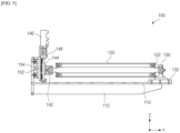
- FIG. 2 is a plan view of the position roller for meander control 100 of FIG. 1
- FIG. 3 is a front view of the position roller for meander control 100 of FIG. 1
- FIG. 4 is a right side view of the position roller for meander control 100 of FIG. 1 .
- the XZ driver 140 includes a Z-axis frame 148 connected to a second ball joint 142 coupled to a proximal end of the rotational axis 122, and an X-axis frame 154 that accommodates the Z-axis frame 148.
- the proximal end of the rotational axis 122 of the roller 120 is also provided with a second ball joint 142, which corresponds to the distal end of the rotational axis 122 being fixed to the first ball joint 130, and the cross-sectional view of FIG. 5 illustrates the fixing structure for the rotational axis 122 of the roller 120.
- the distance of the distal end of the rotational axis 122 to the XZ plane (the distance between a point and a plane) changes, and to accommodate this, the distal end of the rotational axis 122 must be movable.
- the first ball joint 130 is supported to be able to move forward and backward on a Y-axis rail 132 mounted to the base 110.
- the XZ driver 140 causes the second ball joint and the Z-axis frame 148 to move linearly in a two-dimensional plane, and correspondingly, the first ball joint 130 passively moves forward and backward on the Y-axis rail 132.
- the XZ driver 140 when viewed as a whole, comprises a structure in which the Z-axis frame 148 is constrained to move linearly in only one direction, that is, the X-axis direction, with respect to the X-axis frame 154.
- a second ball joint 142 coupled to a proximal end of the rotational axis 122, is coupled about a Z-axis rail 144 to allow linear movement.
- the Z-axis rail 144 extending along the Z-axis direction is installed on the Z-axis frame 148, and a Z-axis driver 146 fixed on the Z-axis frame 148 provides power for the second ball joint 142 to move linearly along the Z-axis rail 144.
- the Z-axis driver 146 may linearly move the second ball joint 142 in a ball screw method.
- a linear driver using another method besides a ball screw method may be applied, and the second ball joint 142 may be provided with a plate coupled to the Z-axis rail 144.
- the entirety of the Z-axis frame 148 is coupled for linear movement relative to the X-axis rail 150 provided in the X-axis frame 154. Coupled to the X-axis rail 150 extending along the X-axis direction, the Z-axis frame 148 can only move in one direction of the X-axis, and power provided by the X-axis driver 152 mounted on the X-axis frame 154 causes the Z-axis frame 148 to move linearly along the X-axis rail 150.
- the second ball joint 142 which couples to the proximal end of the rotational axis 122, is freely movable in the XZ plane by the XZ driver 140, thereby allowing the roller 120 to freely implement a steering movement in the X plane and/or a tilting movement in the Z plane about which the distal end of the rotational axis 122 is a pivot point.
- the meander control device 1000 can be configured by pairing the position rollers for meander control 100 described in detail in the first embodiment.
- FIG. 6 is a diagram illustrating an exemplary embodiment of a meander control device 1000 having the position roller for meander control 100 described above.
- the meander control device 1000 of the present invention includes first and second position rollers for meander control 100-1, 100-2, first and second EPSs 1010, 1020, first and second idle rollers 1110, 1120, and a control part 1200.
- the first and second position rollers for meander control 100-1, 100-2 are the position rollers for meander control 100 described with reference to FIGS. 1 to 5 , and the meander control device 1000 is provided with a pair of position rollers for meander control 100.
- the distal end and the proximal end of the rotational axis 122 are disposed in the same direction.
- the meander control device 1000 includes a first EPS 1010 disposed on the upstream side of the first position roller for meander control 100-1, and a second EPS 1020 disposed on the downstream side of the second position roller for meander control 100-2.
- the edge position sensor (EPS) is a sensor that measures the position of an edge of a traveling web Wb, and the edge information of the web Wb measured by the EPS is used as data to determine the meander direction and angle of the web Wb by comparing it to a reference position.
- a first idle roller 1110 is disposed between the first EPS 1010 and the first position roller for meander control 100-1
- a second idle roller 1120 is disposed between the second position roller for meander control 100-2 and the second EPS 1020.
- the first and second idle rollers 1110, 1120 are idle rollers disposed at the inlet and outlet of the paired position rollers for meander control 100-1, 100-2, respectively, and the traveling direction of the web Wb is switched by the first and second idle rollers 1110, 1120.
- first and second idle rollers 1110, 1120 switching to the Z-axis direction, a tension is applied to the web Wb, and the tension applied to the web Wb generates sufficient friction force between the web Wb and each roller 120 of the first and second position rollers for meander control 100-1, 100-2.
- the meander traveling of the web Wb is achieved by adjusting the traveling direction of the web Wb by changing the angle of the roller 120 to cause a change in the direction of the moment of the center of the web Wb, and the effect of changing the direction of the moment of the center of the web Wb is greatest when there is no slip between the roller 120 and the web Wb.
- first and second idle rollers 1110, 1120 are necessary.
- the control part 1200 controls each XZ driver 140 of the first and second position rollers for meander control 100-1, 100-2 based on the meander traveling information detected by the first EPS 1010, i.e., the meander direction and angle of the web Wb. Basically, the angle of the roller 120 is adjusted to act as a momentator in the opposite direction to the meander direction of the web Wb.
- the second EPS 1020 corresponds to a sensor to check whether the meander of the web Wb is corrected by the first and second position rollers for meander control 100-1, 100-2.
- the control part 1200 can perform feedback control using the meander traveling information detected by the second EPS 1020 as the feedback value. That is, the result of the meander correction to the target value of correcting the meander of the web Wb to be zero is used as the feedback value, so that the meander can be controlled more quickly and effectively.
- control part 1200 can independently control each XZ driver 140 of the first and second position rollers for meander control 100-1, 100-2.
- FIG. 7 is a diagram illustrating an example of controlling an angle of incidence ⁇ 1 and an angle of exit ⁇ 2 of the web Wb by the meander control device 1000, wherein the first and second position rollers for meander control 100-1, 100-2 form different angles.
- each roller 120 can freely implement a steering movement in the X plane and a tilting movement in the Z plane where a distal end of the rotational axis 122 is a pivot point.
- the steering movement has a great ability to control web meander, but it has a disadvantage that the angle of incidence ⁇ 1 and angle of exit ⁇ 2 are limited by the elongation percentage of the material, i.e., the range of meander control is narrow, and it is difficult to respond when the web Wb is lifted in the height direction.
- the tilting movement has less meander control ability than the steering movement, but it has the advantage of minimizing the slip phenomenon that occurs when the web Wb lifts, stretches, and slides.
- the meander control device 1000 of the present invention is provided with first and second position rollers for meander control 100-1, 100-2 capable of implementing both a steering movement in the X plane and a tilting movement in the Z plane, so that the control part 1200 controls each X-axis driver 152 of the first and second position rollers for meander control 100-1, 100-2 to control the angle of incidence ⁇ 1 and angle of exit ⁇ 2 of the traveling web Wb, while controlling (tilting control) the slip of the traveling web Wb by controlling each Z-axis driver 146 of the first and second position rollers for meander control 100-1, 100-2.
- the meander control device 1000 of the present invention has excellent meander control ability by minimizing slip by maximizing the friction force between the web Wb and the roller 120, and is easy to install even in a narrow space because the first and second position rollers for meander control 100-1, 100-2 are structurally independent of each other.
- the steering value and tilting value for the first and second position rollers for meander control 100-1, 100-2 are experimental values, and optimal adjustment values are selected according to the elastic modulus and surface friction coefficient of the web Wb, so there is a limit to expressing them in specific figures, and different measures are established for different materials of the web Wb to perform the meander control of the web Wb.
Landscapes
- Engineering & Computer Science (AREA)
- Manufacturing & Machinery (AREA)
- Chemical & Material Sciences (AREA)
- Chemical Kinetics & Catalysis (AREA)
- Electrochemistry (AREA)
- General Chemical & Material Sciences (AREA)
- Registering, Tensioning, Guiding Webs, And Rollers Therefor (AREA)
Abstract
Description
- The present invention relates to a position roller capable of controlling the meandering of a web member travelling at an angle on a transfer roller.
- This application claims the benefit of priority to
Korean Patent Application No. 10-2022-0114644, filed on September 13, 2022 - With the technological development and increasing demand for mobile devices, the demand for secondary batteries is also increasing rapidly. Among them, lithium secondary batteries are widely used as an energy source for various electronic products, including mobile devices, due to their high energy density, high operating voltage, and excellent preservation and lifetime characteristics.
- A lithium secondary battery has a structure in which an electrode assembly with a porous separator interposed between a positive electrode and negative electrode coated with an active material, respectively, is impregnated with an electrolyte containing lithium salts. A positive electrode active material is mainly composed of lithium cobalt oxide, lithium manganese oxide, lithium nickel oxide, lithium complex oxide, and a negative electrode active material is mainly composed of carbon-based materials. When charging, lithium ions from the positive electrode active material are released and inserted into the carbon layer of the negative electrode, and when discharging, lithium ions from the negative electrode carbon layer are released and inserted into the positive electrode active material, and the electrolyte acts as a medium to transfer lithium ions between the negative electrode and positive electrode.
- Electrode assemblies can be roughly categorized into Jellyroll-type, which is wound with a separator interposed between the positive electrode and negative electrode of an active material-coated sheet, a stack-type, which is a sequential stacking of a plurality of positive electrodes and negative electrodes with a separator interposed therebetween, and a stack & folding type, in which is stack-type unit cells are wound with a long separator film. Secondary batteries are further categorized into coin-type batteries, cylindrical batteries, prismatic batteries, and pouch-type batteries based on the shape of the battery case.
- The manufacturing process of a secondary battery involves the use of large quantities of thin metal films for the positive electrode and negative electrode, thin films for the separator, and, in the case of pouch-type batteries, pouch is manufactured to a laminated sheet for the packaging material. Thin, flexible continuous media such as films, paper, metal films, and the like are collectively referred to as webs (or web members), which are transferred in a roll-to-roll method for the productivity of secondary batteries.
- In the roll-to-roll method, various rollers, including winders and unwinders, transfer rollers, idle rollers, and tension rollers, which wind or unwind the web against the roll, are provided as a transfer device. The web member travels on these various rollers, and a meandering phenomenon often occurs in which the web member travels at an oblique angle to the center of travel.
- Left unchecked, meandering can lead to high defect rates, failure of various devices that process the web, and there may be a need to discard the web member due to folds, breaks, bends, wrinkles, and the like in the web member.
- The meandering is usually compensated by using a meander control device called EPC (Edge Position Controller). The meander control device often uses the pivot centering method, which is a structure in which two rollers are rotatably mounted in one frame, and the meandering is controlled by generating a plane pivot movement relative to the center of the frame. In other words, assuming that there is little slip between the rollers and the web, the traveling direction of the web can be adjusted by changing the angle of the rollers by rotating the frame, causing a change in the moment direction of the web center.
- However, this pivotal centering method uses only one degree of freedom of the center pivot, so it is difficult to respond to lifting in the height direction of the web, and the installation location is limited due to the structure of adjusting by interweaving two rollers into one frame. Another disadvantage is that the size of the frame is fixed, so if the specifications of the transfer equipment are changed, it must be manufactured again with customized specifications.
- The present invention aims to provide a position roller for meander control, which can effectively control a meandering phenomenon occurring in a web transferred by a roll-to-roll method and is easy to install, and a meander control device including the same.
- However, the technical problems that the present invention seeks to address are not limited to those described above, and other problems not mentioned will be apparent to those of ordinary skill in the art from the following description of the invention.
- The present invention relates to a position roller for meander control, which in one example includes a roller with a rotational axis; a first ball joint supporting a distal end among both ends of the rotational axis for pivotal movement; an XZ driver that drives a proximal end among both ends of the rotational axis into two-dimensional motion in a plane; and a base supporting the first ball joint and the XZ driver.
- Here, the first ball joint supports the distal end of the rotational axis so that it can pivot in any direction.
- In addition, the first ball joint is supported to move forward and backward on a Y-axis rail mounted on the base.
- In addition, the XZ driver may include: a second ball joint coupled to the proximal end of the rotational axis; a Z-axis frame having a Z-axis rail to which the second ball joint is coupled for linear movement; a Z-axis driver to provide power for linear movement of the second ball joint along the Z-axis rail; an X-axis frame having an X-axis rail to which the Z-axis frame is coupled for linear movement; and an X-axis driver to provide power for linear movement of the Z-axis frame along the X-axis rail.
- Here, the second ball joint may support the proximal end of the rotational axis for pivoting in any direction.
- In addition, the first ball joint may passively move forward and backward on the Y-axis rail in response to linear movement of the second ball joint and Z-axis frame by the XZ driver.
- Meanwhile, the present invention provides a meander control device including: first and second position rollers for meander control having the above-mentioned configuration; a first edge position sensor (EPS) disposed upstream of the first position roller for meander control; a second EPS disposed downstream of the second position roller for meander control; a first idle roller disposed between the first EPS and the first position roller for meander control; a second idle roller disposed between the second position roller for meander control and the second EPS; and a control part that controls each XZ driver of the first and second position rollers for meander control based on the meander traveling information detected by the first EPS.
- According to an exemplary embodiment of the present invention, the control part may perform feedback control using the meander traveling information detected by the second EPS as the feedback value.
- In addition, the control part may independently control each XZ driver of the first and second position rollers for meander control.
- In addition, the control part may control the XZ driver of the first position roller for meander control to control the angle of incidence of the traveling web, and may control the XZ driver of the second position roller for meander control to control the angle of exit of the traveling web.
- In addition, the control part may control each X-axis driver of the first and second position rollers for meander control to control the angle of incidence and the angle of departure of the traveling web, while controlling each Z-axis driver of the first and second position rollers for meander control to control the slip of the traveling web.
- The position roller for meander control of the present invention with the above configuration, and the meander control device including it, enables the roller to freely implement a steering movement on the X plane and a tilting movement on the Z plane where the rotational axis distal end becomes a pivot point, thereby maximizing the friction force on the web traveling on the roller. As a result, the slip phenomenon of the web is prevented, and the meander control ability is improved as the slip of the web is minimized.
- In addition, the present invention has the advantage that the configuration of the position roller for meander control does not occupy a large space due to the compact arrangement of the roller and the XZ driver on a single base, so it has a high degree of freedom in selecting the installation location.
- However, the technical effects of the present invention are not limited to those described above, and other effects not mentioned will be apparent to one of ordinary skill in the art from the following description of the invention.
- The following drawings, which accompany this specification, are illustrative of preferred embodiments of the present invention and serve to further illustrate the technical ideas of the present invention in conjunction with the detailed description of the invention that follows, and the present invention is not to be construed as limited to what is shown in such drawings.
-
FIG. 1 is a perspective view illustrating a position roller for meander control according to an exemplary embodiment of the present invention. -
FIG. 2 is a plan view of the position roller for meander control ofFIG. 1 . -
FIG. 3 is a front view of the position roller for meander control ofFIG. 1 . -
FIG. 4 is a right side view of the position roller for meander control ofFIG. 1 . -
FIG. 5 is a diagram illustrating the fixing structure of the roller rotational axis in the position roller for meander control ofFIG. 1 . -
FIG. 6 is a diagram illustrating an exemplary embodiment of a meander control device having the position roller for meander control ofFIG. 1 . -
FIG. 7 is a diagram illustrating an exemplary example of controlling the angle of incidence and exit of the web by the meander control device ofFIG. 6 . - The present invention is subject to various modifications and can have many embodiments, certain of which are described in detail below.
- However, this is not intended to limit the present invention to any particular embodiment and is to be understood to include all modifications, equivalents, or substitutions that fall within the scope of the thought and skill of the present invention.
- In this application, it should be understood that terms such as "include" and "have" are intended to indicate the presence of a feature, number, step, operation, component, part, or a combination thereof described in the specification, and they do not preclude the possibility of the presence or addition of one or more other features or numbers, steps, operations, components, parts or combinations thereof.
- Also, when a first portion such as a layer, a film, an area, a plate, etc. is referred to as being "on" a second portion, this includes not only the case where the first portion is "directly on" the second portion, but also the case where a third portion is interposed therebetween. On the other hand, when a first portion such as a layer, a film, an area, a plate, etc. is referred to as being "under" a second portion, this includes not only the case where the first portion is "directly under" the second portion, but also the case where a third portion is interposed therebetween. In addition, to be disposed "on" in the present application may include the case of being disposed at the bottom as well as the top.
- The present invention relates to a position roller for meander control, which in one example includes a roller with a rotational axis, a first ball joint supporting a distal end among both ends of the rotational axis for pivotal movement, an XZ driver that drives a proximal end among both ends of the rotational axis into two-dimensional motion in a plane, and a base supporting the first ball joint and the XZ driver.
- With such a configuration, the position roller for meander control of the present invention enables the proximal end of the rotational axis of the roller to perform a two-dimensional movement combining a steering movement in the X plane and a tilting movement in the Z plane, and enables the distal end of the rotational axis of the roller to passively move forward and backward along the Y axis direction in response, thereby maximizing the friction force on the web traveling on the roller.
- In this way, the slip of the web is prevented as the friction force on the web is maximized, and the ability to control meandering is improved as the slip of the web is minimized. In particular, the position roller for meander control of the present invention has the advantage that the roller and the XZ driver are compactly arranged on one base and do not occupy a large space, so there is a high degree of freedom in selecting the installation location.
- Hereinafter, specific embodiments of the position roller for
meander control 100 of the present invention will be described with reference to the accompanying drawings. For reference, front and rear directions or up, down, left, and right directions for designating relative positions used in the following description are intended to help the understanding of the present invention and are based on directions shown in the drawings unless otherwise specified. -
FIG. 1 is a perspective view of a position roller formeander control 100 according to an exemplary embodiment of the present invention. The position roller formeander control 100 of the present invention can maximize the friction force on the web Wb traveling on theroller 120 by performing a two-dimensional movement in which one end of therotational axis 122 of theroller 120 performs a steering movement in the X plane and a tilting movement in the Z plane. Referring to the drawings, the specific configuration of the position roller formeander control 100 will be described in detail as follows. - Referring to
FIG. 1 , the position roller formeander control 100 of the present invention is provided with asingle roller 120 having arotational axis 122. As will be described later in the detailed description, the position roller formeander control 100 of the present invention is paired to form ameander control device 1000, thereby solving the problem that the installation environment of the conventional meander control device is greatly affected by having two rollers in one frame. - The distal end (relative to the XZ driver position) of the
rotational axis 122 provided in theroller 120 is supported for pivotal movement by the first ball joint 130. As the first ball joint 130, a Spherical Plain Bearing can be applied, and by the first ball joint 130, the distal end of therotational axis 122 can perform omnidirectional pivotal movement in a fixed state. - In addition, the proximal end opposite the two ends of the
rotational axis 122 is coupled to theXZ driver 140, and the proximal end of therotational axis 122 are moved by theXZ driver 140 in a two-dimensional motion in a plane. The angle that theroller 120 makes with respect to the web Wb traveling by theXZ driver 140 is changed, and the direction of the moment of the center of the web Wb is changed accordingly, so that the traveling direction of the web Wb can be adjusted. - The base 110 acts as a pedestal to hold the structure of the position roller for
meander control 100, and the first ball joint 130 and theXZ driver 140 are mounted on thebase 110. In addition, both ends of theroller 120 are indirectly mounted on the base 110 as a suspension structure coupled to the first ball joint 130 and theXZ driver 140, respectively. - For reference, the base 110 in the illustrated embodiment has several through-holes formed for lightweighting, and
vertical ribs 112 bonded to its lower surface to increase structural rigidity. -
FIG. 2 is a plan view of the position roller formeander control 100 ofFIG. 1 ,FIG. 3 is a front view of the position roller formeander control 100 ofFIG. 1 , andFIG. 4 is a right side view of the position roller formeander control 100 ofFIG. 1 . - Referring to
FIG. 1 to describe theXZ driver 140, theXZ driver 140 includes a Z-axis frame 148 connected to a second ball joint 142 coupled to a proximal end of therotational axis 122, and anX-axis frame 154 that accommodates the Z-axis frame 148. - Here, the proximal end of the
rotational axis 122 of theroller 120 is also provided with a second ball joint 142, which corresponds to the distal end of therotational axis 122 being fixed to the first ball joint 130, and the cross-sectional view ofFIG. 5 illustrates the fixing structure for therotational axis 122 of theroller 120. - When the proximal end of the
rotational axis 122 is moved in the two-dimensional plane by theXZ driver 140 and the distal end of therotational axis 122 is pivoted accordingly, the angle formed by the distal end of therotational axis 122 with respect to the XZ plane changes, and to accommodate this, both ends of therotational axis 122 are supported by the first and second ball joints 142, respectively. Thus, the proximal end of therotational axis 122 is supported by the second ball joint 142 to be pivotable in any direction. - In addition, as the proximal end of the
rotational axis 122 is moved in the two-dimensional plane by theXZ driver 140, the distance of the distal end of therotational axis 122 to the XZ plane (the distance between a point and a plane) changes, and to accommodate this, the distal end of therotational axis 122 must be movable. To accomplish this, the first ball joint 130 is supported to be able to move forward and backward on a Y-axis rail 132 mounted to thebase 110. - As a result, the
XZ driver 140 causes the second ball joint and the Z-axis frame 148 to move linearly in a two-dimensional plane, and correspondingly, the first ball joint 130 passively moves forward and backward on the Y-axis rail 132.
Returning again toFIGS. 1 through 4 , the specific configuration of theXZ driver 140 will be described. TheXZ driver 140, when viewed as a whole, comprises a structure in which the Z-axis frame 148 is constrained to move linearly in only one direction, that is, the X-axis direction, with respect to theX-axis frame 154. - A second ball joint 142, coupled to a proximal end of the
rotational axis 122, is coupled about a Z-axis rail 144 to allow linear movement. The Z-axis rail 144 extending along the Z-axis direction is installed on the Z-axis frame 148, and a Z-axis driver 146 fixed on the Z-axis frame 148 provides power for the second ball joint 142 to move linearly along the Z-axis rail 144. For example, the Z-axis driver 146 may linearly move the second ball joint 142 in a ball screw method. - Depending on the embodiment, a linear driver using another method besides a ball screw method may be applied, and the second ball joint 142 may be provided with a plate coupled to the Z-
axis rail 144. - In addition, the entirety of the Z-
axis frame 148, including the Z-axis driver 146, is coupled for linear movement relative to theX-axis rail 150 provided in theX-axis frame 154. Coupled to theX-axis rail 150 extending along the X-axis direction, the Z-axis frame 148 can only move in one direction of the X-axis, and power provided by theX-axis driver 152 mounted on theX-axis frame 154 causes the Z-axis frame 148 to move linearly along theX-axis rail 150. - Eventually, the second ball joint 142, which couples to the proximal end of the
rotational axis 122, is freely movable in the XZ plane by theXZ driver 140, thereby allowing theroller 120 to freely implement a steering movement in the X plane and/or a tilting movement in the Z plane about which the distal end of therotational axis 122 is a pivot point. - The
meander control device 1000 can be configured by pairing the position rollers formeander control 100 described in detail in the first embodiment.FIG. 6 is a diagram illustrating an exemplary embodiment of ameander control device 1000 having the position roller formeander control 100 described above. - Referring to
FIG. 6 , themeander control device 1000 of the present invention includes first and second position rollers for meander control 100-1, 100-2, first andsecond EPSs idle rollers control part 1200. - The first and second position rollers for meander control 100-1, 100-2 are the position rollers for
meander control 100 described with reference toFIGS. 1 to 5 , and themeander control device 1000 is provided with a pair of position rollers formeander control 100. In eachroller 120 of the first and second position rollers for meander control 100-1, 100-2, the distal end and the proximal end of therotational axis 122 are disposed in the same direction. - In addition, the
meander control device 1000 includes afirst EPS 1010 disposed on the upstream side of the first position roller for meander control 100-1, and asecond EPS 1020 disposed on the downstream side of the second position roller for meander control 100-2. The edge position sensor (EPS) is a sensor that measures the position of an edge of a traveling web Wb, and the edge information of the web Wb measured by the EPS is used as data to determine the meander direction and angle of the web Wb by comparing it to a reference position. - A first
idle roller 1110 is disposed between thefirst EPS 1010 and the first position roller for meander control 100-1, and a secondidle roller 1120 is disposed between the second position roller for meander control 100-2 and thesecond EPS 1020. In other words, the first and secondidle rollers idle rollers idle rollers roller 120 of the first and second position rollers for meander control 100-1, 100-2. - The meander traveling of the web Wb is achieved by adjusting the traveling direction of the web Wb by changing the angle of the
roller 120 to cause a change in the direction of the moment of the center of the web Wb, and the effect of changing the direction of the moment of the center of the web Wb is greatest when there is no slip between theroller 120 and the web Wb. In this respect, first and secondidle rollers - The
control part 1200 controls eachXZ driver 140 of the first and second position rollers for meander control 100-1, 100-2 based on the meander traveling information detected by thefirst EPS 1010, i.e., the meander direction and angle of the web Wb. Basically, the angle of theroller 120 is adjusted to act as a momentator in the opposite direction to the meander direction of the web Wb. - And, if the
first EPS 1010 is a sensor to check whether the web Wb is meandering, thesecond EPS 1020 corresponds to a sensor to check whether the meander of the web Wb is corrected by the first and second position rollers for meander control 100-1, 100-2. Thecontrol part 1200 can perform feedback control using the meander traveling information detected by thesecond EPS 1020 as the feedback value. That is, the result of the meander correction to the target value of correcting the meander of the web Wb to be zero is used as the feedback value, so that the meander can be controlled more quickly and effectively. - And, the
control part 1200 can independently control eachXZ driver 140 of the first and second position rollers for meander control 100-1, 100-2.FIG. 7 is a diagram illustrating an example of controlling an angle of incidence α1 and an angle of exit α2 of the web Wb by themeander control device 1000, wherein the first and second position rollers for meander control 100-1, 100-2 form different angles. - Meanwhile, it has been described above that in the first and second position rollers for meander control 100-1, 100-2, each
roller 120 can freely implement a steering movement in the X plane and a tilting movement in the Z plane where a distal end of therotational axis 122 is a pivot point. - The steering movement has a great ability to control web meander, but it has a disadvantage that the angle of incidence α1 and angle of exit α2 are limited by the elongation percentage of the material, i.e., the range of meander control is narrow, and it is difficult to respond when the web Wb is lifted in the height direction. In contrast, the tilting movement has less meander control ability than the steering movement, but it has the advantage of minimizing the slip phenomenon that occurs when the web Wb lifts, stretches, and slides.
- The
meander control device 1000 of the present invention is provided with first and second position rollers for meander control 100-1, 100-2 capable of implementing both a steering movement in the X plane and a tilting movement in the Z plane, so that thecontrol part 1200 controls eachX-axis driver 152 of the first and second position rollers for meander control 100-1, 100-2 to control the angle of incidence α1 and angle of exit α2 of the traveling web Wb, while controlling (tilting control) the slip of the traveling web Wb by controlling each Z-axis driver 146 of the first and second position rollers for meander control 100-1, 100-2. - Therefore, the
meander control device 1000 of the present invention has excellent meander control ability by minimizing slip by maximizing the friction force between the web Wb and theroller 120, and is easy to install even in a narrow space because the first and second position rollers for meander control 100-1, 100-2 are structurally independent of each other. - For reference, the steering value and tilting value for the first and second position rollers for meander control 100-1, 100-2 are experimental values, and optimal adjustment values are selected according to the elastic modulus and surface friction coefficient of the web Wb, so there is a limit to expressing them in specific figures, and different measures are established for different materials of the web Wb to perform the meander control of the web Wb.
- The present invention has been described in more detail above with reference to the drawings and embodiments. However, it is to be understood that the configurations shown in the drawings or embodiments described herein are only one embodiment of the present invention and do not represent all of the technical ideas of the present invention, and that there may be various equivalents and modifications that may replace them at the time of filing the present disclosure.
-
- 100: POSITION ROLLER FOR MEANDER CONTROL
- 110: BASE
- 112: VERTICAL RIB
- 120: ROLLER
- 122: ROTATIONAL AXIS
- 130: FIRST BALL JOINT
- 132: Y-AXIS RAIL
- 140: XZ DRIVER
- 142: SECOND BALL JOINT
- 144: Z-AXIS RAIL
- 146: Z-AXIS DRIVER
- 148: Z-AXIS FRAME
- 150: X-AXIS RAIL
- 152: X-AXIS DRIVER
- 154: X-AXIS FRAME
- 1000: MEANDER CONTROL DEVICE
- 100-1: FIRST POSITION ROLLER FOR MEANDER CONTROL
- 100-2: SECOND POSITION ROLLER FOR MEANDER CONTROL
- 1010: FIRST EPS
- 1020: SECOND EPS
- 1110: FIRST IDLE ROLLER
- 1120: SECOND IDLE ROLLER
- 1200: CONTROL PART
- wb: WEB
- α1: ANGLE OF INCIDENCE
- α2: ANGLE OF EXIT
Claims (11)
- A position roller for meander control comprising:a roller having a rotational axis;a first ball joint supporting a distal end of the roller along the rotational axis, the first ball joint configured to permit pivotal movement of the roller;an XZ driver configured to drive two-dimensional motion of a proximal end of the roller, the two-dimensional motion being in a plane transverse to the rotational axis of the roller; anda base supporting the first ball joint and the XZ driver.
- The position roller of claim 1, wherein the first ball joint supports the distal end of the roller so that the distal end of the roller can pivot in any direction relative to the base.
- The position roller of claim 2, wherein the first ball joint is slidably coupled to a Y-axis rail mounted on the base.
- The position roller of claim 3, wherein the XZ driver comprises:a second ball joint coupled to the proximal end of the roller along the rotational axis;a Z-axis frame having a Z-axis rail to which the second ball joint is slidably coupled for linear movement;a Z-axis driver to provide power for linear movement of the second ball joint along the Z-axis rail;an X-axis frame having an X-axis rail to which the Z-axis frame is slidably coupled for linear movement; andan X-axis driver to provide power for linear movement of the Z-axis frame along the X-axis rail.
- The position roller of claim 4, wherein the second ball joint supports the proximal end of the roller for pivoting of the proximal end of the roller in any direction relative to the base.
- The position roller of claim 5, wherein the first ball joint is configured to passively move forward and backward along the Y-axis rail in response to linear movement of the second ball joint and Z-axis frame driven by the XZ driver.
- A meander control device comprising:first and second position rollers each being the position roller according to claim 1;a first edge position sensor (EPS) disposed upstream of the first position roller and configured to provide meander control of the first position roller;a second EPS disposed downstream of the second position roller and configured to provide meander control of the second position roller;a first idle roller disposed between the first EPS and the first position roller;a second idle roller disposed between the second position roller and the second EPS; anda control part that is configured to control the XZ driver of each of the first and second position rollers to provide meander control based on meander traveling information detected by the first EPS.
- The meander control device of claim 7, wherein the control part is configured to perform feedback control using meander traveling information detected by the second EPS as a feedback value.
- The meander control device of claim 8, wherein the control part is configured to independently control the XZ driver of each of the first and second position rollers.
- The meander control device of claim 9, wherein the control part is configured to control the XZ driver of the first position roller to control an angle of incidence of the traveling web, and the control part is configured to control the XZ driver of the second position roller to control an angle of exit of the traveling web.
- The meander control device of claim 10, wherein the control part is configured to control the X-axis driver of each of the first and second position rollers to control the angle of incidence and the angle of exit of the traveling web, while controlling the Z-axis driver of each of the first and second position rollers to control slip of the traveling web.
Applications Claiming Priority (2)
| Application Number | Priority Date | Filing Date | Title |
|---|---|---|---|
| KR1020220114644A KR20240036186A (en) | 2022-09-13 | 2022-09-13 | Position roller for controlling web meandering |
| PCT/KR2023/013685 WO2024058533A1 (en) | 2022-09-13 | 2023-09-13 | Position roller for controlling web telescoping |
Publications (2)
| Publication Number | Publication Date |
|---|---|
| EP4455065A1 true EP4455065A1 (en) | 2024-10-30 |
| EP4455065A4 EP4455065A4 (en) | 2025-07-02 |
Family
ID=90275562
Family Applications (1)
| Application Number | Title | Priority Date | Filing Date |
|---|---|---|---|
| EP23865830.6A Pending EP4455065A4 (en) | 2022-09-13 | 2023-09-13 | POSITION ROLLER FOR CONTROLLING THE TELESCOPING OF A TRACK |
Country Status (6)
| Country | Link |
|---|---|
| US (1) | US20250145401A1 (en) |
| EP (1) | EP4455065A4 (en) |
| JP (1) | JP7775558B2 (en) |
| KR (1) | KR20240036186A (en) |
| CN (1) | CN118613433A (en) |
| WO (1) | WO2024058533A1 (en) |
Families Citing this family (1)
| Publication number | Priority date | Publication date | Assignee | Title |
|---|---|---|---|---|
| KR20240082576A (en) * | 2022-12-02 | 2024-06-11 | 주식회사 엘지에너지솔루션 | Pouch film supply device for secondary battery |
Family Cites Families (14)
| Publication number | Priority date | Publication date | Assignee | Title |
|---|---|---|---|---|
| US3069056A (en) * | 1960-04-13 | 1962-12-18 | Ind Ovens Inc | Web guiding and edge stretching means |
| JP3174959B2 (en) * | 1991-09-13 | 2001-06-11 | 旭化成株式会社 | Winding device |
| KR100953073B1 (en) * | 2002-11-26 | 2010-04-13 | 주식회사 포스코 | Furnace Strip Heat Deflection Prevention Device |
| JP2008044787A (en) * | 2006-07-20 | 2008-02-28 | Nitto Denko Corp | Film conveying method, film conveying apparatus, film and sheet-like product |
| JP4636117B2 (en) * | 2008-05-09 | 2011-02-23 | トヨタ自動車株式会社 | Meander control system and meander control method |
| JP2010143755A (en) * | 2008-12-22 | 2010-07-01 | Panasonic Electric Works Co Ltd | Winding device for laminated plate material |
| KR101311115B1 (en) * | 2011-09-28 | 2013-09-25 | 현대제철 주식회사 | Loop Structure for Strip Transfer |
| DE102012005439A1 (en) * | 2012-03-20 | 2013-09-26 | Texmag Gmbh Vertriebsgesellschaft | Device for influencing a running web |
| US10370214B2 (en) * | 2017-05-31 | 2019-08-06 | Cryovac, Llc | Position control system and method |
| KR101990990B1 (en) * | 2017-10-18 | 2019-06-20 | 주식회사 포스코 | Vertical type looper having apparatus for correcting strip bias |
| US11384299B2 (en) | 2019-12-19 | 2022-07-12 | Saudi Arabian Oil Company | Systems and processes for upgrading and converting crude oil to petrochemicals through steam cracking |
| KR102407716B1 (en) * | 2020-05-27 | 2022-06-10 | 주식회사 포스코 | Apparatus for correcting meandering of strip |
| KR102210392B1 (en) | 2020-08-10 | 2021-02-01 | 주식회사 엠플러스 | Electrode derailment correction apparatus by electrode automatic tension adjustment and electrode derailment correction method thereby |
| CN112141784A (en) * | 2020-10-26 | 2020-12-29 | 苏州工业职业技术学院 | An adaptive tilt-correcting device |
-
2022
- 2022-09-13 KR KR1020220114644A patent/KR20240036186A/en active Pending
-
2023
- 2023-09-13 JP JP2024543855A patent/JP7775558B2/en active Active
- 2023-09-13 EP EP23865830.6A patent/EP4455065A4/en active Pending
- 2023-09-13 US US18/832,765 patent/US20250145401A1/en active Pending
- 2023-09-13 WO PCT/KR2023/013685 patent/WO2024058533A1/en not_active Ceased
- 2023-09-13 CN CN202380018099.5A patent/CN118613433A/en active Pending
Also Published As
| Publication number | Publication date |
|---|---|
| JP7775558B2 (en) | 2025-11-26 |
| WO2024058533A1 (en) | 2024-03-21 |
| KR20240036186A (en) | 2024-03-20 |
| CN118613433A (en) | 2024-09-06 |
| JP2025502500A (en) | 2025-01-24 |
| US20250145401A1 (en) | 2025-05-08 |
| EP4455065A4 (en) | 2025-07-02 |
Similar Documents
| Publication | Publication Date | Title |
|---|---|---|
| CN113273009B (en) | Apparatus for manufacturing electrode assembly, electrode assembly manufactured thereby, and secondary battery | |
| KR102012957B1 (en) | Electrode body fabrication device and method | |
| KR102819967B1 (en) | Electrode assembly manufacturing device, electrode assembly manufactured from thereof and rechargeable battery | |
| JP5384078B2 (en) | Laminating device for continuous separator and sheet electrode | |
| JP2019194988A (en) | Electrode assembly manufacturing apparatus and method, and electrode assembly manufactured using the same | |
| KR102333754B1 (en) | swing module of electrode assembly manufacturing apparatus | |
| US20250145401A1 (en) | Position Roller for Web Meander Control | |
| US20250357521A1 (en) | Cell stack manufacturing device for secondary batteries | |
| KR102324209B1 (en) | Secondary battery stacking device using pendulum motion | |
| KR20230135936A (en) | Machine for Manufacturing Cell Stack of Secondary Battery | |
| KR101965707B1 (en) | Winder for electrode assembly of rechargeable battery | |
| KR102796439B1 (en) | Secondary battery electrode plate manufacturing device and manufacturing method | |
| KR102468973B1 (en) | System for producing electrodes of battery | |
| EP4546477A1 (en) | Unwinding device for secondary battery manufacturing and secondary battery manufacturing system including same | |
| KR102778526B1 (en) | Electrode plate stacking apparatus having pivotal unwinder for separator | |
| KR102877284B1 (en) | Film supplying unit | |
| CN117245198A (en) | A composite current collector tab welding machine | |
| KR20230083249A (en) | Separator automatic feeder | |
| KR20230115073A (en) | Cell storage device for secondary batteries | |
| JP7794527B2 (en) | Automatic separator supply device | |
| EP4560753A1 (en) | Secondary battery manufacturing apparatus and secondary battery manufacturing method using the same | |
| US20250300326A1 (en) | Busbar holder and battery module | |
| CN121925729A (en) | Electrode joint guiding device | |
| KR20260022893A (en) | Secondary battery cell stack maunfacturing device and control method thereof | |
| KR20260018429A (en) | Film member replacement apparatus and film member replacement method |
Legal Events
| Date | Code | Title | Description |
|---|---|---|---|
| STAA | Information on the status of an ep patent application or granted ep patent |
Free format text: STATUS: THE INTERNATIONAL PUBLICATION HAS BEEN MADE |
|
| PUAI | Public reference made under article 153(3) epc to a published international application that has entered the european phase |
Free format text: ORIGINAL CODE: 0009012 |
|
| STAA | Information on the status of an ep patent application or granted ep patent |
Free format text: STATUS: REQUEST FOR EXAMINATION WAS MADE |
|
| 17P | Request for examination filed |
Effective date: 20240722 |
|
| AK | Designated contracting states |
Kind code of ref document: A1 Designated state(s): AL AT BE BG CH CY CZ DE DK EE ES FI FR GB GR HR HU IE IS IT LI LT LU LV MC ME MK MT NL NO PL PT RO RS SE SI SK SM TR |
|
| A4 | Supplementary search report drawn up and despatched |
Effective date: 20250602 |
|
| RIC1 | Information provided on ipc code assigned before grant |
Ipc: H01M 10/04 20060101ALI20250526BHEP Ipc: B65H 23/038 20060101AFI20250526BHEP |
|
| DAV | Request for validation of the european patent (deleted) | ||
| DAX | Request for extension of the european patent (deleted) | ||
| STAA | Information on the status of an ep patent application or granted ep patent |
Free format text: STATUS: EXAMINATION IS IN PROGRESS |
|
| 17Q | First examination report despatched |
Effective date: 20260319 |