EP4455026A1 - Apparatus for performing a processing operation on an object housed in a conveyor - Google Patents
Apparatus for performing a processing operation on an object housed in a conveyor Download PDFInfo
- Publication number
- EP4455026A1 EP4455026A1 EP24170334.7A EP24170334A EP4455026A1 EP 4455026 A1 EP4455026 A1 EP 4455026A1 EP 24170334 A EP24170334 A EP 24170334A EP 4455026 A1 EP4455026 A1 EP 4455026A1
- Authority
- EP
- European Patent Office
- Prior art keywords
- conveyor
- operating condition
- processing
- processing station
- positioning device
- Prior art date
- Legal status (The legal status is an assumption and is not a legal conclusion. Google has not performed a legal analysis and makes no representation as to the accuracy of the status listed.)
- Pending
Links
- 238000012545 processing Methods 0.000 title claims abstract description 145
- 238000007789 sealing Methods 0.000 claims description 10
- 230000000284 resting effect Effects 0.000 claims description 2
- 239000000463 material Substances 0.000 description 8
- 230000009471 action Effects 0.000 description 5
- 210000001520 comb Anatomy 0.000 description 5
- 235000013305 food Nutrition 0.000 description 4
- 230000003993 interaction Effects 0.000 description 4
- 238000004806 packaging method and process Methods 0.000 description 3
- 239000004033 plastic Substances 0.000 description 3
- 229920003023 plastic Polymers 0.000 description 3
- 230000000717 retained effect Effects 0.000 description 3
- 238000013519 translation Methods 0.000 description 3
- 239000001913 cellulose Substances 0.000 description 2
- 229920002678 cellulose Polymers 0.000 description 2
- 230000008878 coupling Effects 0.000 description 2
- 238000010168 coupling process Methods 0.000 description 2
- 238000005859 coupling reaction Methods 0.000 description 2
- 238000000034 method Methods 0.000 description 2
- 230000008569 process Effects 0.000 description 2
- 238000003856 thermoforming Methods 0.000 description 2
- 229920000219 Ethylene vinyl alcohol Polymers 0.000 description 1
- 238000004026 adhesive bonding Methods 0.000 description 1
- XAGFODPZIPBFFR-UHFFFAOYSA-N aluminium Chemical compound [Al] XAGFODPZIPBFFR-UHFFFAOYSA-N 0.000 description 1
- 229910052782 aluminium Inorganic materials 0.000 description 1
- 239000004411 aluminium Substances 0.000 description 1
- 238000013459 approach Methods 0.000 description 1
- QVGXLLKOCUKJST-UHFFFAOYSA-N atomic oxygen Chemical compound [O] QVGXLLKOCUKJST-UHFFFAOYSA-N 0.000 description 1
- 230000004888 barrier function Effects 0.000 description 1
- 239000011248 coating agent Substances 0.000 description 1
- 238000000576 coating method Methods 0.000 description 1
- 230000002950 deficient Effects 0.000 description 1
- 230000001419 dependent effect Effects 0.000 description 1
- 230000008030 elimination Effects 0.000 description 1
- 238000003379 elimination reaction Methods 0.000 description 1
- UFRKOOWSQGXVKV-UHFFFAOYSA-N ethene;ethenol Chemical compound C=C.OC=C UFRKOOWSQGXVKV-UHFFFAOYSA-N 0.000 description 1
- 239000004715 ethylene vinyl alcohol Substances 0.000 description 1
- 238000012423 maintenance Methods 0.000 description 1
- 239000007769 metal material Substances 0.000 description 1
- 238000012544 monitoring process Methods 0.000 description 1
- 229910052760 oxygen Inorganic materials 0.000 description 1
- 239000001301 oxygen Substances 0.000 description 1
- 238000009466 skin packaging Methods 0.000 description 1
Images



Classifications
-
- B—PERFORMING OPERATIONS; TRANSPORTING
- B65—CONVEYING; PACKING; STORING; HANDLING THIN OR FILAMENTARY MATERIAL
- B65B—MACHINES, APPARATUS OR DEVICES FOR, OR METHODS OF, PACKAGING ARTICLES OR MATERIALS; UNPACKING
- B65B31/00—Packaging articles or materials under special atmospheric or gaseous conditions; Adding propellants to aerosol containers
- B65B31/02—Filling, closing, or filling and closing, containers or wrappers in chambers maintained under vacuum or superatmospheric pressure or containing a special atmosphere, e.g. of inert gas
- B65B31/025—Filling, closing, or filling and closing, containers or wrappers in chambers maintained under vacuum or superatmospheric pressure or containing a special atmosphere, e.g. of inert gas specially adapted for rigid or semi-rigid containers
- B65B31/028—Filling, closing, or filling and closing, containers or wrappers in chambers maintained under vacuum or superatmospheric pressure or containing a special atmosphere, e.g. of inert gas specially adapted for rigid or semi-rigid containers closed by a lid sealed to the upper rim of the container, e.g. tray-like container
-
- B—PERFORMING OPERATIONS; TRANSPORTING
- B65—CONVEYING; PACKING; STORING; HANDLING THIN OR FILAMENTARY MATERIAL
- B65B—MACHINES, APPARATUS OR DEVICES FOR, OR METHODS OF, PACKAGING ARTICLES OR MATERIALS; UNPACKING
- B65B31/00—Packaging articles or materials under special atmospheric or gaseous conditions; Adding propellants to aerosol containers
- B65B31/02—Filling, closing, or filling and closing, containers or wrappers in chambers maintained under vacuum or superatmospheric pressure or containing a special atmosphere, e.g. of inert gas
-
- B—PERFORMING OPERATIONS; TRANSPORTING
- B65—CONVEYING; PACKING; STORING; HANDLING THIN OR FILAMENTARY MATERIAL
- B65B—MACHINES, APPARATUS OR DEVICES FOR, OR METHODS OF, PACKAGING ARTICLES OR MATERIALS; UNPACKING
- B65B31/00—Packaging articles or materials under special atmospheric or gaseous conditions; Adding propellants to aerosol containers
- B65B31/02—Filling, closing, or filling and closing, containers or wrappers in chambers maintained under vacuum or superatmospheric pressure or containing a special atmosphere, e.g. of inert gas
- B65B31/025—Filling, closing, or filling and closing, containers or wrappers in chambers maintained under vacuum or superatmospheric pressure or containing a special atmosphere, e.g. of inert gas specially adapted for rigid or semi-rigid containers
-
- B—PERFORMING OPERATIONS; TRANSPORTING
- B65—CONVEYING; PACKING; STORING; HANDLING THIN OR FILAMENTARY MATERIAL
- B65B—MACHINES, APPARATUS OR DEVICES FOR, OR METHODS OF, PACKAGING ARTICLES OR MATERIALS; UNPACKING
- B65B51/00—Devices for, or methods of, sealing or securing package folds or closures; Devices for gathering or twisting wrappers, or necks of bags
- B65B51/10—Applying or generating heat or pressure or combinations thereof
-
- B—PERFORMING OPERATIONS; TRANSPORTING
- B65—CONVEYING; PACKING; STORING; HANDLING THIN OR FILAMENTARY MATERIAL
- B65B—MACHINES, APPARATUS OR DEVICES FOR, OR METHODS OF, PACKAGING ARTICLES OR MATERIALS; UNPACKING
- B65B7/00—Closing containers or receptacles after filling
- B65B7/16—Closing semi-rigid or rigid containers or receptacles not deformed by, or not taking-up shape of, contents, e.g. boxes or cartons
-
- B—PERFORMING OPERATIONS; TRANSPORTING
- B65—CONVEYING; PACKING; STORING; HANDLING THIN OR FILAMENTARY MATERIAL
- B65B—MACHINES, APPARATUS OR DEVICES FOR, OR METHODS OF, PACKAGING ARTICLES OR MATERIALS; UNPACKING
- B65B7/00—Closing containers or receptacles after filling
- B65B7/16—Closing semi-rigid or rigid containers or receptacles not deformed by, or not taking-up shape of, contents, e.g. boxes or cartons
- B65B7/162—Closing semi-rigid or rigid containers or receptacles not deformed by, or not taking-up shape of, contents, e.g. boxes or cartons by feeding web material to securing means
-
- B—PERFORMING OPERATIONS; TRANSPORTING
- B65—CONVEYING; PACKING; STORING; HANDLING THIN OR FILAMENTARY MATERIAL
- B65B—MACHINES, APPARATUS OR DEVICES FOR, OR METHODS OF, PACKAGING ARTICLES OR MATERIALS; UNPACKING
- B65B7/00—Closing containers or receptacles after filling
- B65B7/16—Closing semi-rigid or rigid containers or receptacles not deformed by, or not taking-up shape of, contents, e.g. boxes or cartons
- B65B7/162—Closing semi-rigid or rigid containers or receptacles not deformed by, or not taking-up shape of, contents, e.g. boxes or cartons by feeding web material to securing means
- B65B7/164—Securing by heat-sealing
Definitions
- This invention relates to an apparatus for performing a processing operation on an object which, specifically, is housed in a conveyor.
- this invention is applied for performing a processing operation on an object which may be constituted of a product, such as a food product, or of a container, such as a container which is intended to be part of a package and which may contain or support a product.
- this invention can be applied in an apparatus for performing at least one step of a process linked to packaging of a product on a container having the shape of a tray or a tub.
- this invention relates to an apparatus for performing a processing operation on an object which is housed in a conveyor: the conveyor is moved by a movement system which brings it into a processing station, in which the processing operation takes place on the object which is located in the conveyor.
- Prior art apparatuses of this type usually comprise the movement system and at least one conveyor which is moved by the movement system along the movement path.
- the object conveyed by the conveyor is therefore brought into one or more processing stations, where it is processed by a processing tool.
- the movement system comprises a pair of opposing combs that bring the conveyors from the outside of the processing stations into the inside of the processing station: the conveyor is initially located out of the processing station and is caught by the opposing combs, which approach each other; after having caught the conveyor between them, the opposing combs move along the movement path to bring the conveyor into the processing station, where the conveyor is released by the combs which move away from each other; the combs then go back to the initial position by translating backwards and exiting the processing station.
- the movement system may position the object imprecisely in the processing station and therefore the processing operation may be defective or incorrectly performed.
- the film may be fixed off centre or film seals on the container may not be suitable because they are too close to the edges of the container.
- the conveying system (that is to say, the movement system) is of the type with linear motors or planar motors, where there are plays or mechanical degrees of freedom which make it difficult to achieve precise and stable positioning of the object conveyed in the processing station.
- the technical purpose which forms the basis of this invention is to provide an apparatus for performing a processing operation on an object which overcomes the above-mentioned disadvantage or which at least offers an alternative solution to the prior art solutions.
- the apparatus comprises a positioning device which is configured to act on the conveyor in a pause position - to which the conveyor was brought by the movement system - in order to position and/or retain the at least one conveyor in a processing position in which the object can be processed by the processing tool.
- the positioning device corrects any positioning imprecisions by the movement system and brings the conveyor into the predetermined position which is required for the processing operation.
- the positioning device can retain the conveyor in that position, thereby eliminating any play that the conveyor could have.
- the positioning device is switchable between a non-operating condition and an operating condition.
- the positioning device is a centring device which centres the conveyor relative to the processing tool.
- the positioning of the conveyor (and of the object conveyed by it) in the processing station substantially occurs in two steps: a first step in which the movement system brings the conveyor into the processing station and stops it in a position (pause position) which is very near to the predetermined position, but not coincident due to imprecisions and plays; a second step in which the positioning device acts on the conveyor and shifts it into and/or retains it in a position which is the predetermined position, so that the processing operation can take place without the above-mentioned disadvantage.
- the positioning device comprises a first member and a second member which are configured to make contact on opposite sides with a body of the conveyor.
- the first member is shiftable relative to the second member.
- the positioning device also comprises an actuator for shifting the first member relative to the second member when the positioning device is switched from the non-operating condition to the operating condition, and vice versa. Whilst in the non-operating condition the first member and the second member do not interfere with the movement of the conveyor and with the reaching of the pause position, in the operating condition the first member and the second member hold the body of the conveyor between them.
- the actuator shifts the first member towards the conveyor and in this way the first member pushes the conveyor towards the second member. In this way the conveyor is positioned and/or retained in the predetermined processing position, which is defined by the positioning device in the operating condition.
- This embodiment of the positioning device is easily implementable and usable.
- the first member is movable and the second member is a fixed contact element against which the conveyor is pushed by the first member under the action of the actuator.
- the second member is also movable and is connected to the actuator, so that the first member and the second member are both shifted towards the conveyor.
- the first member in order to improve the action of the positioning device on the conveyor, has a recessed seat which is intended to receive a corresponding projection from the body of the conveyor, or the first member has a projection which is intended to be received in a corresponding recessed seat of the body of the conveyor.
- This interaction required between the seat and the projection is useful for defining in an even more precise way the processing position which the conveyor must adopt in the operating condition.
- the same solution can be adopted for the second member too.
- the latter can be configured to receive multiple conveyors in respective pause positions and the positioning device can be configured to act simultaneously on the conveyors in the pause positions, in order to position and/or retain the conveyors in the respective processing positions.
- the movement system is of the type with linear motors or planar motors.
- the conveyor is a carriage or a shuttle which magnetically interacts with the movement system. After the conveyor has been brought to the pause position by the movement system with linear motors or planar motors, the positioning device acts on the conveyor to correct any positioning imprecisions by this movement system and/or to eliminate any mechanical degrees of freedom or plays in the coupling between the conveyor and the parts forming the movement system.
- an apparatus for performing a processing operation on an object is indicated with the reference number 1 and is schematically shown in Figure 1 , where only a processing station - indicated with the reference number 2 - is shown in greater detail.
- Figure 1 shows that the apparatus 1 also comprises two other stations, which are shown as simple rectangles and are for example a loading station 11 and an unloading station 13, and a movement path 15 which passes through said stations.
- the apparatus 1 comprises at least one conveyor 3 which has a housing 30 for housing the object to be processed in the processing station 2.
- the at least one conveyor has two housings 30 (see Figure 8 ) and therefore can simultaneously house two objects to be processed.
- the at least one conveyor 3 (which hereinafter for brevity will be referred to simply as “the conveyor 3") is movable along the movement path 15, which passes through the processing station 2 and has a pause position in the processing station 2.
- the processing station 2 comprises a lane 25 which defines a stretch of the movement path 15, the conveyor 3 being movable along the lane 25.
- the apparatus 1 also comprises a movement system for moving the conveyor 3 along the movement path 15 and for bringing the conveyor 3 to the pause position.
- the movement system moves the conveyor 3 (thereby conveying the object in the housing 30 along the movement path 15 between the different stations) and stops the conveyor 3 in the pause position in the processing station 2. After the processing operation has been performed, the movement system again moves the conveyor 3 to bring it out of the processing station 2.
- the movement system is of the type with linear motors (or if necessary with planar motors) and the conveyor 3 is a carriage or a shuttle which magnetically interacts with the movement system.
- the movement system comprises a guide 18 with linear motors, which defines the movement path 15 and is a stator of the movement system with linear motors, whilst the conveyor 3 comprises a moved device 38, which magnetically interacts with the guide 18 and runs along the guide 18.
- the conveyor 3 also comprises a body 31 which is mounted on the moved device 38 and which defines the housing 30. If necessary, in an alternative the body 31 and the moved device 38 may constitute a single body.
- the processing station 2 has a processing tool 21 for performing the processing operation.
- processing tool shall be understood as a device which is configured to perform the processing operation on the object which is located in the processing station 2.
- the processing tool 21 is movable between a home position (for example, in which the processing tool 21 is lifted towards the top of the processing station 2, as shown in Figures 1 to 4 ) and an operating position (for example, in which the processing tool 21 is lowered towards the conveyor 3 in the pause position, as shown in Figures 14 and 15 ).
- the processing station 2 is a sealing station
- the object is a container having the shape of a tray or a tub (that is to say, having a substantially flat shape in a lying plane or having a concavity) and the processing operation to be performed on the object is an application of a film on the container, so that the film is sealed on the container.
- the processing tool 21 is a sealing head which is movable towards the conveyor 3; the conveyor 3 acts as a contact element onto which the sealing head presses the container and the film.
- the film in a first type of processing station the film is sealed on the container to close and/or to seal a product which is located on the container, in a second type of processing station the film is sealed on the container to form a coating of the container itself before a product is positioned on the container.
- the processing station 2 comprises for example a modified-atmosphere sealing machine, a vacuum sealing machine, a skin packaging machine, or more generally a closing machine; in the second type, the processing station 2 comprises for example a thermoforming machine for thermoforming the film on the container, or a machine for gluing the film on the container.
- the container is for example made of material derived from cellulose and/or plant fibres, such as cardboard, or may be plastic-material based or metal-material based (for example aluminium), or is made of different materials (for example, plastic material and cellulose material), whilst the film is for example made of thermoformable plastic material, if necessary comprising a layer which is a barrier to oxygen (for example a layer of EVOH).
- One specific sector of application of this invention is the packaging of food products, therefore the product in the container is a food product. That shall not be understood as limiting and the invention is also applicable to the packaging of non-food products.
- the apparatus 1 is characterised by the fact that the processing station 2 comprises a positioning device 4 which is configured to act on the conveyor 3 in the pause position in order to position and/or retain the conveyor 3 in a processing position in which the object can be processed by the processing tool 21.
- the positioning device 4 is switchable between a non-operating condition (shown in Figures 10 and 11 ) and an operating condition (shown in Figures 12 and 13 ).
- the positioning device 4 acts on the conveyor 3 which is located in the pause position and brings it into a desired position for the processing operation (if the movement system did not precisely position the conveyor 3 in the desired position), then retaining it in that desired position, or directly retains it in the desired position (if the movement system precisely positioned the conveyor 3).
- the pause position in which the movement system brings and stops the conveyor 3 in the processing station 2, can be not coincident with the processing position due to imprecisions and plays.
- the positioning device 4, acting on the conveyor 3 in the pause position in the processing station 2, is configured to correct any positioning imprecisions by the movement system.
- the positioning device 4 is a centring device which centres the conveyor 3 (and the object conveyed) relative to the processing tool 21, so that the latter can operate correctly and precisely.
- the action of the positioning device 4 allows the elimination of any play in the coupling between the guide 18 and the moved device 38 of the conveyor 3 and/or between the moved device 38 and the body 31 of the conveyor 3.
- the positioning device 4 comprises a first member 41 and a second member 42 which are configured to make contact on opposite sides with the body 31 of the conveyor 3.
- the first member 41 is shiftable relative to the second member 42 and the positioning device 4 also comprises an actuator 45 for shifting the first member 41 relative to the second member 42 when the positioning device is switched from the non-operating condition to the operating condition, and vice versa.
- the movement system can bring the conveyor 3 into the pause position without being hindered by the positioning device 4.
- the actuator 45 shifts the first member 41 relative to the conveyor 3 in the pause position and the first member 41 pushes the conveyor 3 in the pause position towards the second member 42, thereby positioning and/or retaining the conveyor 3 in the processing position. Therefore, the first member 41 and the second member 42 make contact with the body 31 of the conveyor 3. Specifically, the balance between the thrusts applied by the first member 41 and by the second member 42 on the two opposite sides of the body 31 of the conveyor 3 guarantees positioning and retaining of the conveyor 3 itself in the correct position for the processing operation.
- first member 41 and the second member 42 hold the body 31 of the conveyor 3 between them, which therefore remains retained in the processing position.
- the switching of the positioning device from the operating condition to the non-operating condition returns the first member 41 to the initial position and the body 31 of the conveyor 3 is freed from being retained, so that the movement system can restart the conveyor 3 towards the outfeed from the processing station 2.
- the second member 42 is also shiftable by the actuator 45 relative to the first member 41, that is to say, the first member 41 and the second member 42 are both movable relative to a fixed structure 29 of the processing station 2.
- the positioning device 4 is switched from the non-operating condition to the operating condition, the first member 41 and the second member 42 are both shifted relative to the conveyor 3 in the pause position.
- the actuator 45 may comprise two (or more) actuating units 451 which are operated in a coordinated way to shift the first member 41 and the second member 42.
- the actuator 45 or the actuating unit 451 is for example a hydraulic cylinder, a pneumatic cylinder or a motor. If necessary, the actuator 45 or the actuating unit 451 may comprise a spring for performing one of the two movements of the respective member 41, 42, for example for returning the latter to the non-operating condition.
- first member 41 is movable relative to the fixed structure 29, whilst the second member 42 is stationary and is a contact element against which the body 31 of the conveyor 3 is pushed by the first member 41.
- the first member 41 and the second member 42 are positioned on opposite sides of the lane 25, that is to say, they are on opposite sides relative to the stretch of movement path 15 which the conveyor 3 can travel along.
- the first member 41 is shiftable relative to the second member 42 along a line of shifting which is transversal or perpendicular to the lane 25.
- the shifting movement of the first member 41 (and if necessary of the second member 42) is an alternating movement towards and away from the lane 25 and the other member.
- the first member 41 and the second member 42 In the operating condition (that is to say, in a near condition) the first member 41 and the second member 42 have a distance between them which is less than a distance between the same members 41, 42 in the non-operating condition (that is to say, in a far away condition).
- the first member 41 and the second member 42 form a gripper which grasps / releases the conveyor 3 in the processing station 2: the conveyor is grasped in the pause position in the processing station 2 and is released in the processing position in the processing station 2.
- the first member 41 is shiftable relative to the second member 42 according to a movement which takes place in a horizontal plane. That movement is a translation in the horizontal plane, alternatively it could be a roto-translation or a pure translation.
- the body 31 of the conveyor 3 has a first projection 33, which in the pause position is directed towards the first member 41, and a second projection 34, which in the pause position is directed towards the second member 42.
- the first member 41 and the second member 42 each have a recessed seat 43, 44 intended to receive the respective first projection 33 or second projection 34 when, in the operating condition, the first member 41 and the second member 42 are in contact with the body 31 of the conveyor 3.
- the seats 43, 44 have a U shape or a V shape which is open towards the respective projection 33, 34.
- the projections 33, 34 are substantially shaped to match the respective seats 43, 44.
- the seats 43, 44 receive the projections 33, 34 and can perform an action centring the conveyor 3 even to correct its position along the movement line 15 (that is to say, along the lane 25) and/or its angular position (in particular the angular position relative to a vertical axis of rotation).
- the interaction between the seats 43, 44 and the projections 33, 34 prevents any unwanted movement of the conveyor 3 along the lane 25 or around a vertical axis. Therefore, the seats 43, 44 precisely define the processing position which the conveyor 3 must adopt.
- the projections 33, 34 would be out of alignment relative to the seats 43, 44 and would prevent the first member 41 (and if necessary the second member 42) from reaching the position required for the operating condition of the positioning device 4. That can be detected by a monitoring system and suitably managed as an operating error situation, in order to avoid an incorrect processing operation and to allow adjustment of the movement system.
- the projections 33, 34 are shown as protrusions of the body 31, however they may be simple teeth or pins. The important aspect is that they can interact with the respective seats 43, 44 when the conveyor 3 is in the pause position and the positioning device 4 goes into the operating condition.
- An alternative and equivalent solution (not shown in the figures) is that wherein the body 31 of the conveyor 3 has a first recessed seat which opens towards the first member 41 and a second recessed seat which opens towards the second member 42, the first member 41 and the second member 42 each having a projection intended to be received in the respective first recessed seat or second recessed seat when, in the operating condition, the first member and the second member are in contact with the body 31 of the conveyor 3.
- Another alternative and equivalent solution is a combination of the two above solutions, that is to say, the body 31 of the conveyor 3 has a first recessed seat, which opens towards one of the two members 41, 42, and a first projection, which is directed towards the other of the two members 41, 42.
- One of the two members 41, 42 has a second projection and the other of the two members 41, 42, has a second recessed seat, so that when, in the operating condition, the first member 41 and the second member 42 are in contact with the body 31 of the conveyor 3 the first projection is intended to be received in the second recessed seat and the second projection is intended to be received in the first recessed seat.
- the first member 41 and the second member 42 each have a plurality of said recessed seats 43, 44, which are positioned one after another relative to the movement path 15 (that is to say, they are spaced apart from each other along the movement path 15 and the lane 25).
- the first member 41 and the second member 42 have a comb shape, in which the recessed seats open on one side of a plate-shaped body 46, said side being parallel to the lane 25 and directed towards the other member 42, 41.
- first member 41 and/or the second member 42 each have a plurality of said projections, which are positioned one after another relative to the movement path 15.
- the processing station 2 is configured to perform the processing operation simultaneously on a plurality of objects and the apparatus 1 comprises a plurality of conveyors 3.
- Each conveyor 3 has the housing 30 for housing a respective object of said plurality of objects.
- the movement path 15 has a plurality of pause positions in the processing station 2 and the movement system is suitable for bringing the conveyors 3 into the respective pause positions, so that all of the pause positions are occupied.
- the conveyors 3 are structurally independent of each other and are movable independently of each other, despite all being moved by the movement system in a coordinated way.
- Figures 1 , 3 and 5 show a processing station 2 which can simultaneously receive nine conveyors 3 (each of which has two housings 30, so that the total number of objects simultaneously processable is eighteen). Therefore, the processing station 2 has nine pause positions, which are positioned one after another relative to the movement path 15.
- the positioning device 4 is configured to act simultaneously on the conveyors 3 in the pause positions, in order to position and/or retain the conveyors 3 in the respective processing positions.
- first member 41 and the second member 42 each have a plurality of said recessed seats 43, 44 (or a plurality of said projections) which are positioned one after another relative to the movement path 15, are useful (although not essential) for this purpose.
- Figures 6, 7 , 10 and 12 it can be seen how each member 41, 42 has nine respective recessed seats 43, 44, each for a respective projection 33, 34 of one of the nine conveyors 3; see also Figures 3 to 5 .
- the processing station 2 comprises a supporting surface 27 for the body 31 of the conveyor 3 during the processing operation, in which the body 31 is interposed between the supporting surface 27 and the processing tool 21.
- the supporting surface 27, which is stationary relative to the fixed structure 29, is divided into two parts which are separated by the lane 25.
- the body 31 of the conveyor 3 has a bottom 35 and a perimetric frame 36.
- the perimetric frame 36 is spaced apart from the supporting surface 27 when the bottom 35 is resting on the supporting surface 27, so that a cavity 37 is present between the perimetric frame 36 and the supporting surface 27.
- the housing 30 is located above the perimetric frame 36 and the bottom 35 is located below the perimetric frame 36: the cavity 37 is delimited at the top by the perimetric frame 36 which projects relative to the perimeter of the bottom 35.
- the first member 41 and the second member 42 are positioned above the supporting surface 27 (specifically, the supporting surface 27 defines the horizontal plane on which the first member 41 is shiftable relative to the second member 42) and they are inserted into the cavity 37 when, in the operating condition, the first member 41 and the second member 42 are in contact on opposite sides with the body 31 of the conveyor 3. That is shown in Figure 13 . It should be noticed that the projections 33, 34 - which in the embodiment illustrated do not project from the perimetric frame 36 - are accessible in the cavity 37.
- the first member 41 and the second member 42 have a height which is less than a height of said cavity 37 (again see Figure 13 ).
- the processing tool 21 presses the body 31 of the conveyor 3 onto the supporting surface 27, the first member 41 and the second member 42 are not subjected to any thrust towards the supporting surface 27 and therefore there is no risk of damaging them. It should be noticed that, in the operating condition, the first member 41 and the second member 42 if necessary can allow a small movement of the body 31 of the conveyor 3 towards the supporting surface 27 under the action applied by the processing tool 21.
- Figures 14 and 15 show the processing station 2 while the processing operation is performed: the positioning device 4 is in the operating condition and the processing tool 21 has descended towards the conveyor 3 and the object contained in it.
- the processing tool 21 is a sealing head which, in Figures 14 and 15 , presses the container and the film against the conveyor 3, which acts as a contact element and in turn is pressed against the supporting surface 27. (It does not seem necessary herein to provide further details about this operation, since it can be performed according to the prior art.)
- the movement system brings the conveyors 3 into the respective pause positions in the processing station 2; a control system activates the positioning device 4, which goes to the operating condition and brings the conveyors 3 into and/or retains them in the respective processing positions; the control system activates the processing tool 21, which performs the processing operation on the objects in the conveyors 3; at the end of the processing operation, the control system makes the processing tool 21 return to the home position and returns the positioning device 4 to the non-operating condition; the movement system starts the conveyors 3 and makes them come out of the processing station 2.
- the first member 41 and the second member 42 each have a plate-shaped body 46 in which the recessed seats 43, 44 are made.
- Each recessed seat 43, 44 is defined by a respective element 47, for example made of plastic or rubbery material, which is removably mounted on the plate-shaped body 46.
- the elements 47 when worn or damaged, can be removed and replaced by new elements 47.
- the first member 41 and the second member 42 each have a support 48 which is connected to the actuator 45 (in particular, each support is connected to two actuating units 451) and is moved by the actuator 45 between the non-operating condition and the operating condition.
- the plate-shaped body 46 is mounted on the respective support 48 and moves with it.
- the plate-shaped body 46 is removable from the respective support 48 and can be replaced by another plate-shaped body 46 for maintenance or to perform a size changeover. For example, in the latter case the plate-shaped body 46 is replaced by another plate-shaped body 46 having recessed seats 43, 44 with a different distance.
Landscapes
- Engineering & Computer Science (AREA)
- Mechanical Engineering (AREA)
- Chemical & Material Sciences (AREA)
- Dispersion Chemistry (AREA)
- Special Conveying (AREA)
Abstract
An apparatus (1) for processing an object comprises a processing station (2), at least one conveyor (3) having a housing (30) for the object, a movement system for moving the conveyor (3) along a movement path (15) and for bringing it into a pause position in the processing station (2). A positioning device (4) is configured to act on the conveyor (3) in the pause position in order to position and/or retain the conveyor (3) in a processing position. The positioning device (4) comprises a first member (41) and a second member (42) which are configured to make contact on opposite sides with a body (31) of the conveyor (3). The positioning device (4) comprises an actuator (45) for shifting the first member (41) relative to the second member (42) when the positioning device (4) is switched from a non-operating condition to an operating condition, and vice versa.
Description
- This invention relates to an apparatus for performing a processing operation on an object which, specifically, is housed in a conveyor. In particular, this invention is applied for performing a processing operation on an object which may be constituted of a product, such as a food product, or of a container, such as a container which is intended to be part of a package and which may contain or support a product. Specifically, this invention can be applied in an apparatus for performing at least one step of a process linked to packaging of a product on a container having the shape of a tray or a tub.
- As indicated above, this invention relates to an apparatus for performing a processing operation on an object which is housed in a conveyor: the conveyor is moved by a movement system which brings it into a processing station, in which the processing operation takes place on the object which is located in the conveyor.
- Prior art apparatuses of this type usually comprise the movement system and at least one conveyor which is moved by the movement system along the movement path. The object conveyed by the conveyor is therefore brought into one or more processing stations, where it is processed by a processing tool.
- Some apparatuses of this type are disclosed for example in
US 9,162,825 B2 GB 2 517 145 AWO 2018/018016 A1 ,EP 3 945 037 A1 ,EP 3 938 280 A1 ,EP 3 733 530 A1 . In at least some of these prior art documents (in particular, inUS 9,162,825 B2 - The inventors of this invention noticed a disadvantage in the prior art apparatuses: the movement system may position the object imprecisely in the processing station and therefore the processing operation may be defective or incorrectly performed.
- For example, in the case of a processing operation which is the application of a film on a container, the film may be fixed off centre or film seals on the container may not be suitable because they are too close to the edges of the container.
- The inventors of this invention noticed that this disadvantage may be particularly felt if the conveying system (that is to say, the movement system) is of the type with linear motors or planar motors, where there are plays or mechanical degrees of freedom which make it difficult to achieve precise and stable positioning of the object conveyed in the processing station.
- In this context the technical purpose which forms the basis of this invention is to provide an apparatus for performing a processing operation on an object which overcomes the above-mentioned disadvantage or which at least offers an alternative solution to the prior art solutions.
- The technical purpose and the aims indicated are substantially achieved by an apparatus as defined in
independent claim 1. Particular embodiments of this invention are defined in the corresponding dependent claims. - According to one aspect of this invention, the apparatus comprises a positioning device which is configured to act on the conveyor in a pause position - to which the conveyor was brought by the movement system - in order to position and/or retain the at least one conveyor in a processing position in which the object can be processed by the processing tool. In other words, the positioning device corrects any positioning imprecisions by the movement system and brings the conveyor into the predetermined position which is required for the processing operation. Moreover, the positioning device can retain the conveyor in that position, thereby eliminating any play that the conveyor could have. The positioning device is switchable between a non-operating condition and an operating condition. Specifically, the positioning device is a centring device which centres the conveyor relative to the processing tool.
- The positioning of the conveyor (and of the object conveyed by it) in the processing station substantially occurs in two steps: a first step in which the movement system brings the conveyor into the processing station and stops it in a position (pause position) which is very near to the predetermined position, but not coincident due to imprecisions and plays; a second step in which the positioning device acts on the conveyor and shifts it into and/or retains it in a position which is the predetermined position, so that the processing operation can take place without the above-mentioned disadvantage.
- According to another aspect of this invention, the positioning device comprises a first member and a second member which are configured to make contact on opposite sides with a body of the conveyor. The first member is shiftable relative to the second member. The positioning device also comprises an actuator for shifting the first member relative to the second member when the positioning device is switched from the non-operating condition to the operating condition, and vice versa. Whilst in the non-operating condition the first member and the second member do not interfere with the movement of the conveyor and with the reaching of the pause position, in the operating condition the first member and the second member hold the body of the conveyor between them. In the switching from the non-operating condition to the operating condition, the actuator shifts the first member towards the conveyor and in this way the first member pushes the conveyor towards the second member. In this way the conveyor is positioned and/or retained in the predetermined processing position, which is defined by the positioning device in the operating condition. This embodiment of the positioning device is easily implementable and usable.
- In a simple version, the first member is movable and the second member is a fixed contact element against which the conveyor is pushed by the first member under the action of the actuator. In an alternative version, the second member is also movable and is connected to the actuator, so that the first member and the second member are both shifted towards the conveyor.
- In particular embodiments, in order to improve the action of the positioning device on the conveyor, the first member has a recessed seat which is intended to receive a corresponding projection from the body of the conveyor, or the first member has a projection which is intended to be received in a corresponding recessed seat of the body of the conveyor. This interaction required between the seat and the projection is useful for defining in an even more precise way the processing position which the conveyor must adopt in the operating condition. The same solution can be adopted for the second member too.
- If it is necessary to simultaneously process multiple objects in the same processing station, the latter can be configured to receive multiple conveyors in respective pause positions and the positioning device can be configured to act simultaneously on the conveyors in the pause positions, in order to position and/or retain the conveyors in the respective processing positions. In a particular embodiment, the movement system is of the type with linear motors or planar motors. The conveyor is a carriage or a shuttle which magnetically interacts with the movement system. After the conveyor has been brought to the pause position by the movement system with linear motors or planar motors, the positioning device acts on the conveyor to correct any positioning imprecisions by this movement system and/or to eliminate any mechanical degrees of freedom or plays in the coupling between the conveyor and the parts forming the movement system. Further features and the advantages of this invention will be more apparent in the detailed description of a preferred, non-limiting embodiment of an apparatus for performing a processing operation on an object. Reference will be made to the accompanying drawings, in which:
-
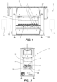
Figure 1 is a front view of a processing station made according to this invention; -
Figure 2 is a side view of the processing station ofFigure 1 ; -
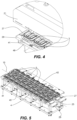
Figure 3 is a perspective view of the processing station ofFigure 1 , with some parts removed to show the internal components; -
Figure 4 is an enlarged view of a detail ofFigure 3 ; -
Figure 5 is a perspective view of the processing station as inFigure 3 , with further parts removed; -
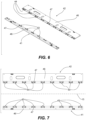
Figure 6 is a perspective view of two members which are part of a positioning device which is part of the processing station ofFigure 1 ; -
Figure 7 is a top view of the two members ofFigure 6 ; -
Figure 8 is a perspective view of a body of a conveyor used in the processing station ofFigure 1 ; -
Figure 9 is a bottom view of the body of the conveyor ofFigure 8 ; -
Figure 10 is a perspective view of the processing station as inFigure 3 , with further parts removed to show the positioning device in the non-operating condition; -
Figure 11 is a side view of the processing station ofFigure 1 , with parts removed to show the positioning device in the non-operating condition; -
Figure 12 is a perspective view of the processing station as inFigure 3 , with further parts removed to show the positioning device in the operating condition; -
Figure 13 is a side view of the processing station ofFigure 1 , with parts removed to show the positioning device in the operating condition; -
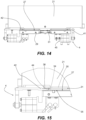
Figure 14 is a side view of the processing station ofFigure 1 , with parts removed to show the positioning device in the operating condition and a processing step; -
Figure 15 is an enlarged view of a detail ofFigure 14 . - With reference to the above-mentioned figures, an apparatus for performing a processing operation on an object is indicated with the
reference number 1 and is schematically shown inFigure 1 , where only a processing station - indicated with the reference number 2 - is shown in greater detail. By way of example only,Figure 1 shows that theapparatus 1 also comprises two other stations, which are shown as simple rectangles and are for example aloading station 11 and anunloading station 13, and amovement path 15 which passes through said stations. - The
apparatus 1 comprises at least oneconveyor 3 which has ahousing 30 for housing the object to be processed in theprocessing station 2. In the particular embodiment illustrated, the at least one conveyor has two housings 30 (seeFigure 8 ) and therefore can simultaneously house two objects to be processed. - The at least one conveyor 3 (which hereinafter for brevity will be referred to simply as "the
conveyor 3") is movable along themovement path 15, which passes through theprocessing station 2 and has a pause position in theprocessing station 2. Specifically, theprocessing station 2 comprises alane 25 which defines a stretch of themovement path 15, theconveyor 3 being movable along thelane 25. - The
apparatus 1 also comprises a movement system for moving theconveyor 3 along themovement path 15 and for bringing theconveyor 3 to the pause position. - Therefore, during operation of the
apparatus 1 the movement system moves the conveyor 3 (thereby conveying the object in thehousing 30 along themovement path 15 between the different stations) and stops theconveyor 3 in the pause position in theprocessing station 2. After the processing operation has been performed, the movement system again moves theconveyor 3 to bring it out of theprocessing station 2. - In the specific embodiment illustrated, the movement system is of the type with linear motors (or if necessary with planar motors) and the
conveyor 3 is a carriage or a shuttle which magnetically interacts with the movement system. In particular, the movement system comprises aguide 18 with linear motors, which defines themovement path 15 and is a stator of the movement system with linear motors, whilst theconveyor 3 comprises amoved device 38, which magnetically interacts with theguide 18 and runs along theguide 18. Theconveyor 3 also comprises abody 31 which is mounted on themoved device 38 and which defines thehousing 30. If necessary, in an alternative thebody 31 and the moveddevice 38 may constitute a single body. - It should be emphasised that the aspects strictly linked to operation of the movement system with linear motors or with planar motors, in particular operation of the linear motors themselves and the interaction with the carriage or shuttle, are aspects which are in themselves known to a person skilled in the art and will not be explained in further detail in the following description. Moreover, examples and details can be found in European patent application No.
EP22174692.8 EP23169057.9 - The
processing station 2 has aprocessing tool 21 for performing the processing operation. The expression "processing tool" shall be understood as a device which is configured to perform the processing operation on the object which is located in theprocessing station 2. In particular, theprocessing tool 21 is movable between a home position (for example, in which theprocessing tool 21 is lifted towards the top of theprocessing station 2, as shown inFigures 1 to 4 ) and an operating position (for example, in which theprocessing tool 21 is lowered towards theconveyor 3 in the pause position, as shown inFigures 14 and 15 ). - In the specific embodiment illustrated, the
processing station 2 is a sealing station, the object is a container having the shape of a tray or a tub (that is to say, having a substantially flat shape in a lying plane or having a concavity) and the processing operation to be performed on the object is an application of a film on the container, so that the film is sealed on the container. - In this embodiment, the
processing tool 21 is a sealing head which is movable towards theconveyor 3; theconveyor 3 acts as a contact element onto which the sealing head presses the container and the film. - In particular: in a first type of processing station the film is sealed on the container to close and/or to seal a product which is located on the container, in a second type of processing station the film is sealed on the container to form a coating of the container itself before a product is positioned on the container.
- In the first type, the
processing station 2 comprises for example a modified-atmosphere sealing machine, a vacuum sealing machine, a skin packaging machine, or more generally a closing machine; in the second type, theprocessing station 2 comprises for example a thermoforming machine for thermoforming the film on the container, or a machine for gluing the film on the container. - It should be noticed that in the figures the object, the container, the product and the film are not shown. However, they are aspects which are in themselves known to a person skilled in the art. Moreover, examples and details can be found in European patent application No.
EP22174692.8 EP23169057.9 - Here what is indicated is simply that the container is for example made of material derived from cellulose and/or plant fibres, such as cardboard, or may be plastic-material based or metal-material based (for example aluminium), or is made of different materials (for example, plastic material and cellulose material), whilst the film is for example made of thermoformable plastic material, if necessary comprising a layer which is a barrier to oxygen (for example a layer of EVOH).
- One specific sector of application of this invention is the packaging of food products, therefore the product in the container is a food product. That shall not be understood as limiting and the invention is also applicable to the packaging of non-food products.
- The
apparatus 1 according to this invention is characterised by the fact that theprocessing station 2 comprises apositioning device 4 which is configured to act on theconveyor 3 in the pause position in order to position and/or retain theconveyor 3 in a processing position in which the object can be processed by theprocessing tool 21. For this purpose, thepositioning device 4 is switchable between a non-operating condition (shown inFigures 10 and 11 ) and an operating condition (shown inFigures 12 and 13 ). - Essentially, the
positioning device 4 acts on theconveyor 3 which is located in the pause position and brings it into a desired position for the processing operation (if the movement system did not precisely position theconveyor 3 in the desired position), then retaining it in that desired position, or directly retains it in the desired position (if the movement system precisely positioned the conveyor 3). - Indeed, the pause position, in which the movement system brings and stops the
conveyor 3 in theprocessing station 2, can be not coincident with the processing position due to imprecisions and plays. Thepositioning device 4, acting on theconveyor 3 in the pause position in theprocessing station 2, is configured to correct any positioning imprecisions by the movement system. In other words, thepositioning device 4 is a centring device which centres the conveyor 3 (and the object conveyed) relative to theprocessing tool 21, so that the latter can operate correctly and precisely. - In the context of the movement system with linear motors, the action of the
positioning device 4 allows the elimination of any play in the coupling between theguide 18 and the moveddevice 38 of theconveyor 3 and/or between themoved device 38 and thebody 31 of theconveyor 3. - In detail, the
positioning device 4 comprises afirst member 41 and asecond member 42 which are configured to make contact on opposite sides with thebody 31 of theconveyor 3. Thefirst member 41 is shiftable relative to thesecond member 42 and thepositioning device 4 also comprises anactuator 45 for shifting thefirst member 41 relative to thesecond member 42 when the positioning device is switched from the non-operating condition to the operating condition, and vice versa. - In the non-operating condition the
first member 41 and thesecond member 42 do not interfere with a movement of theconveyor 3 along themovement path 15 in theprocessing station 2. Therefore, the movement system can bring theconveyor 3 into the pause position without being hindered by thepositioning device 4. - During switching of the positioning device from the non-operating condition to the operating condition, the
actuator 45 shifts thefirst member 41 relative to theconveyor 3 in the pause position and thefirst member 41 pushes theconveyor 3 in the pause position towards thesecond member 42, thereby positioning and/or retaining theconveyor 3 in the processing position. Therefore, thefirst member 41 and thesecond member 42 make contact with thebody 31 of theconveyor 3. Specifically, the balance between the thrusts applied by thefirst member 41 and by thesecond member 42 on the two opposite sides of thebody 31 of theconveyor 3 guarantees positioning and retaining of theconveyor 3 itself in the correct position for the processing operation. - In the operating condition the
first member 41 and thesecond member 42 hold thebody 31 of theconveyor 3 between them, which therefore remains retained in the processing position. - After the processing operation, the switching of the positioning device from the operating condition to the non-operating condition returns the
first member 41 to the initial position and thebody 31 of theconveyor 3 is freed from being retained, so that the movement system can restart theconveyor 3 towards the outfeed from theprocessing station 2. - In the specific embodiment illustrated, the
second member 42 is also shiftable by theactuator 45 relative to thefirst member 41, that is to say, thefirst member 41 and thesecond member 42 are both movable relative to a fixedstructure 29 of theprocessing station 2. When thepositioning device 4 is switched from the non-operating condition to the operating condition, thefirst member 41 and thesecond member 42 are both shifted relative to theconveyor 3 in the pause position. - In particular, the
actuator 45 may comprise two (or more) actuatingunits 451 which are operated in a coordinated way to shift thefirst member 41 and thesecond member 42. Theactuator 45 or theactuating unit 451 is for example a hydraulic cylinder, a pneumatic cylinder or a motor. If necessary, theactuator 45 or theactuating unit 451 may comprise a spring for performing one of the two movements of therespective member - Alternatively to the embodiment with both
members first member 41 is movable relative to the fixedstructure 29, whilst thesecond member 42 is stationary and is a contact element against which thebody 31 of theconveyor 3 is pushed by thefirst member 41. - In the embodiment illustrated, the
first member 41 and thesecond member 42 are positioned on opposite sides of thelane 25, that is to say, they are on opposite sides relative to the stretch ofmovement path 15 which theconveyor 3 can travel along. Thefirst member 41 is shiftable relative to thesecond member 42 along a line of shifting which is transversal or perpendicular to thelane 25. In other words, the shifting movement of the first member 41 (and if necessary of the second member 42) is an alternating movement towards and away from thelane 25 and the other member. - In the operating condition (that is to say, in a near condition) the
first member 41 and thesecond member 42 have a distance between them which is less than a distance between thesame members first member 41 and thesecond member 42 form a gripper which grasps / releases theconveyor 3 in the processing station 2: the conveyor is grasped in the pause position in theprocessing station 2 and is released in the processing position in theprocessing station 2. - As can be seen in the figures, the
first member 41 is shiftable relative to thesecond member 42 according to a movement which takes place in a horizontal plane. That movement is a translation in the horizontal plane, alternatively it could be a roto-translation or a pure translation. - In order to make the interaction between the
positioning device 4 and theconveyor 3 more effective, thebody 31 of theconveyor 3 has afirst projection 33, which in the pause position is directed towards thefirst member 41, and asecond projection 34, which in the pause position is directed towards thesecond member 42. - The
first member 41 and thesecond member 42 each have a recessedseat first projection 33 orsecond projection 34 when, in the operating condition, thefirst member 41 and thesecond member 42 are in contact with thebody 31 of theconveyor 3. Theseats respective projection projections respective seats seats projections conveyor 3 even to correct its position along the movement line 15 (that is to say, along the lane 25) and/or its angular position (in particular the angular position relative to a vertical axis of rotation). In the operating condition of thepositioning device 4 the interaction between theseats projections conveyor 3 along thelane 25 or around a vertical axis. Therefore, theseats conveyor 3 must adopt. - It should also be noticed that, if the movement system were to stop the
conveyor 3 in a pause position far from the one required, theprojections seats positioning device 4. That can be detected by a monitoring system and suitably managed as an operating error situation, in order to avoid an incorrect processing operation and to allow adjustment of the movement system. - In the figures the
projections body 31, however they may be simple teeth or pins. The important aspect is that they can interact with therespective seats conveyor 3 is in the pause position and thepositioning device 4 goes into the operating condition. An alternative and equivalent solution (not shown in the figures) is that wherein thebody 31 of theconveyor 3 has a first recessed seat which opens towards thefirst member 41 and a second recessed seat which opens towards thesecond member 42, thefirst member 41 and thesecond member 42 each having a projection intended to be received in the respective first recessed seat or second recessed seat when, in the operating condition, the first member and the second member are in contact with thebody 31 of theconveyor 3. - Another alternative and equivalent solution (also not shown in the figures) is a combination of the two above solutions, that is to say, the
body 31 of theconveyor 3 has a first recessed seat, which opens towards one of the twomembers members members members first member 41 and thesecond member 42 are in contact with thebody 31 of theconveyor 3 the first projection is intended to be received in the second recessed seat and the second projection is intended to be received in the first recessed seat. - As already indicated, these are equivalent solutions which allow substantially the same result to be achieved as indicated above for the solution illustrated in the figures.
- In particular, as shown in the figures, the
first member 41 and thesecond member 42 each have a plurality of said recessedseats movement path 15 and the lane 25). - In practice, the
first member 41 and thesecond member 42 have a comb shape, in which the recessed seats open on one side of a plate-shapedbody 46, said side being parallel to thelane 25 and directed towards theother member - In equivalent solutions, the
first member 41 and/or thesecond member 42 each have a plurality of said projections, which are positioned one after another relative to themovement path 15. - In the embodiment illustrated in the figures, the
processing station 2 is configured to perform the processing operation simultaneously on a plurality of objects and theapparatus 1 comprises a plurality ofconveyors 3. Eachconveyor 3 has thehousing 30 for housing a respective object of said plurality of objects. Themovement path 15 has a plurality of pause positions in theprocessing station 2 and the movement system is suitable for bringing theconveyors 3 into the respective pause positions, so that all of the pause positions are occupied. In particular, theconveyors 3 are structurally independent of each other and are movable independently of each other, despite all being moved by the movement system in a coordinated way. - For example,
Figures 1 ,3 and5 show aprocessing station 2 which can simultaneously receive nine conveyors 3 (each of which has twohousings 30, so that the total number of objects simultaneously processable is eighteen). Therefore, theprocessing station 2 has nine pause positions, which are positioned one after another relative to themovement path 15. - In this embodiment the
positioning device 4 is configured to act simultaneously on theconveyors 3 in the pause positions, in order to position and/or retain theconveyors 3 in the respective processing positions. - The embodiments described above, in which the
first member 41 and thesecond member 42 each have a plurality of said recessedseats 43, 44 (or a plurality of said projections) which are positioned one after another relative to themovement path 15, are useful (although not essential) for this purpose. InFigures 6, 7 ,10 and12 it can be seen how eachmember seats respective projection conveyors 3; see alsoFigures 3 to 5 . - In the embodiment illustrated, the
processing station 2 comprises a supportingsurface 27 for thebody 31 of theconveyor 3 during the processing operation, in which thebody 31 is interposed between the supportingsurface 27 and theprocessing tool 21. In particular the supportingsurface 27, which is stationary relative to the fixedstructure 29, is divided into two parts which are separated by thelane 25. - The
body 31 of theconveyor 3 has a bottom 35 and aperimetric frame 36. Theperimetric frame 36 is spaced apart from the supportingsurface 27 when the bottom 35 is resting on the supportingsurface 27, so that acavity 37 is present between theperimetric frame 36 and the supportingsurface 27. Essentially, thehousing 30 is located above theperimetric frame 36 and the bottom 35 is located below the perimetric frame 36: thecavity 37 is delimited at the top by theperimetric frame 36 which projects relative to the perimeter of the bottom 35. - The
first member 41 and thesecond member 42 are positioned above the supporting surface 27 (specifically, the supportingsurface 27 defines the horizontal plane on which thefirst member 41 is shiftable relative to the second member 42) and they are inserted into thecavity 37 when, in the operating condition, thefirst member 41 and thesecond member 42 are in contact on opposite sides with thebody 31 of theconveyor 3. That is shown inFigure 13 . It should be noticed that theprojections 33, 34 - which in the embodiment illustrated do not project from the perimetric frame 36 - are accessible in thecavity 37. - The
first member 41 and thesecond member 42 have a height which is less than a height of said cavity 37 (again seeFigure 13 ). - Therefore, when the processing tool 21 (in particular, the sealing head) presses the
body 31 of theconveyor 3 onto the supportingsurface 27, thefirst member 41 and thesecond member 42 are not subjected to any thrust towards the supportingsurface 27 and therefore there is no risk of damaging them. It should be noticed that, in the operating condition, thefirst member 41 and thesecond member 42 if necessary can allow a small movement of thebody 31 of theconveyor 3 towards the supportingsurface 27 under the action applied by theprocessing tool 21. -
Figures 14 and 15 show theprocessing station 2 while the processing operation is performed: thepositioning device 4 is in the operating condition and theprocessing tool 21 has descended towards theconveyor 3 and the object contained in it. In particular theprocessing tool 21 is a sealing head which, inFigures 14 and 15 , presses the container and the film against theconveyor 3, which acts as a contact element and in turn is pressed against the supportingsurface 27. (It does not seem necessary herein to provide further details about this operation, since it can be performed according to the prior art.) - To summarise the operating steps of the processing station 2: with the
positioning device 4 in the non-operating condition and theprocessing tool 21 in a home position, the movement system brings theconveyors 3 into the respective pause positions in theprocessing station 2; a control system activates thepositioning device 4, which goes to the operating condition and brings theconveyors 3 into and/or retains them in the respective processing positions; the control system activates theprocessing tool 21, which performs the processing operation on the objects in theconveyors 3; at the end of the processing operation, the control system makes theprocessing tool 21 return to the home position and returns thepositioning device 4 to the non-operating condition; the movement system starts theconveyors 3 and makes them come out of theprocessing station 2. - The same steps also occur if there is only one
conveyor 3 and a single pause position. - It seems appropriate to emphasise several details of the embodiment. The
first member 41 and thesecond member 42 each have a plate-shapedbody 46 in which the recessedseats seat respective element 47, for example made of plastic or rubbery material, which is removably mounted on the plate-shapedbody 46. Theelements 47, when worn or damaged, can be removed and replaced bynew elements 47. - The
first member 41 and thesecond member 42 each have asupport 48 which is connected to the actuator 45 (in particular, each support is connected to two actuating units 451) and is moved by theactuator 45 between the non-operating condition and the operating condition. The plate-shapedbody 46 is mounted on therespective support 48 and moves with it. The plate-shapedbody 46 is removable from therespective support 48 and can be replaced by another plate-shapedbody 46 for maintenance or to perform a size changeover. For example, in the latter case the plate-shapedbody 46 is replaced by another plate-shapedbody 46 having recessedseats - The invention described above may be modified and adapted in several ways without thereby departing from the scope of the attached claims.
- All details may be substituted with other technically equivalent elements and the materials used, as well as the shapes and dimensions of the various components, may vary according to requirements.
Claims (14)
- An apparatus (1) for performing a processing operation on an object, comprising:a processing station (2) which has a processing tool (21);at least one conveyor (3) which has a housing (30) for housing the object;a movement path (15) which passes through the processing station (2) and has a pause position in the processing station (2), the at least one conveyor (3) being movable along the movement path (15);a movement system for moving the at least one conveyor (3) along the movement path (15) and for bringing the at least one conveyor (3) to the pause position;characterised in thatthe processing station (2) comprises a positioning device (4) configured to act on the at least one conveyor (3) in the pause position in the processing station (2) in order to position and/or retain the at least one conveyor (3) in a processing position in which the object can be processed by the processing tool (21),wherein the positioning device (4) is switchable between a non-operating condition and an operating condition, the positioning device (4) comprising a first member (41) and a second member (42) which are configured to make contact on opposite sides with a body (31) of the at least one conveyor (3), the first member (41) being shiftable relative to the second member (42), the positioning device (4) also comprising an actuator (45) for shifting the first member (41) relative to the second member (42) when the positioning device (4) is switched from the non-operating condition to the operating condition, and vice versa,wherein in the non-operating condition the first member (41) and the second member (42) do not interfere with a movement of the at least one conveyor (3) along the movement path (15) in the processing station (2), and in the operating condition the first member (41) and the second member (42) hold the body (31) of the at least one conveyor (3) between them,wherein, when the positioning device (4) is switched from the non-operating condition to the operating condition, the actuator (45) shifts the first member (41) relative to the at least one conveyor (3) in the pause position and the first member (41) pushes the at least one conveyor (3) in the pause position towards the second member (42), thereby positioning and/or retaining the at least one conveyor (3) in the processing position.
- The apparatus (1) according to claim 1, wherein the positioning device (4), acting on the at least one conveyor (3) in the pause position in the processing station (2), is configured to correct any positioning imprecisions by the movement system, the pause position in which the movement system brings and stops the at least one conveyor (3) in the processing station being not coincident with the processing position due to imprecisions and plays.
- The apparatus (1) according to claim 1 or 2, wherein the positioning device (4) is a centring device which centres the at least one conveyor (3) relative to the processing tool (21).
- The apparatus (1) according to any one of claims 1 to 3, wherein the second member (42) is shiftable by the actuator (45) relative to the first member (41), so that when the positioning device (4) is switched from the non-operating condition to the operating condition the first member (41) and the second member (42) are both shifted relative to the at least one conveyor (3) in the pause position.
- The apparatus (1) according to any one of claims 1 to 4, wherein the processing station (2) comprises a lane (25) which defines a stretch of the movement path (15), the first member (41) and the second member (42) being positioned on opposite sides of the lane (25), the first member (41) being shiftable relative to the second member (42) along a line of shifting which is transversal or perpendicular to the lane (25).
- The apparatus (1) according to claim 5, wherein the first member (41) and the second member (42) form a gripper which grasps the at least one conveyor (3) in the processing station (2) and releases the at least one conveyor (3) in the processing station (2),
wherein, when the positioning device (4) is switched from the non-operating condition to the operating condition, and vice versa, the shifting movement of the first member (41) and of the second member (42) is an alternating movement towards and away from the lane (25) and the other member. - The apparatus (1) according to any one of claims 1 to 6, wherein the first member (41) is shiftable relative to the second member (42) according to a movement which takes place in a horizontal plane.
- The apparatus (1) according to any one of claims 1 to 7,wherein the body (31) of the at least one conveyor (3) has a first projection (33) directed towards the first member (41) and a second projection (34) directed towards the second member (42), the first member (41) and the second member (42) each having a recessed seat (43, 44) intended to receive the respective first projection (33) or second projection (34) when, in the operating condition, the first member (41) and the second member (42) are in contact with the body (31) of the at least one conveyor (3),
orwherein the body of the at least one conveyor has a first recessed seat which opens towards the first member and a second recessed seat which opens towards the second member, the first member and the second member each having a projection intended to be received in the respective first recessed seat or second recessed seat when, in the operating condition, the first member and the second member are in contact with the body of the at least one conveyor,
orwherein the body of the at least one conveyor has a first recessed seat, which opens towards one of either the first member or the second member, and a first projection, which is directed towards the other of either the first member or the second member, one of either the first member or the second member having a second projection and the other of either the first member or the second member having a second recessed seat, so that when, in the operating condition, the first member and the second member are in contact with the body of the conveyor the first projection is intended to be received in the second recessed seat and the second projection is intended to be received in the first recessed seat. - The apparatus (1) according to claim 8,
wherein the first member (41) and the second member (42) each have a plurality of said recessed seats (43, 44) or a plurality of said projections, said recessed seats (43, 44) or said projections being positioned one after another relative to the movement path (15). - The apparatus (1) according to any one of claims 1 to 9, wherein the processing station (2) is configured to perform the processing operation simultaneously on a plurality of said objects and the apparatus (1) comprises a plurality of said conveyors (3), each conveyor (3) of said plurality of conveyors having the housing (30) for housing a respective object of said plurality of objects and the movement path (15) having a plurality of pause positions in the processing station (2), the movement system being suitable for bringing the conveyors (3) into the respective pause positions,
the positioning device (4) being configured to act simultaneously on the conveyors (3) in the pause positions in order to position and/or retain the conveyors (3) in respective processing positions. - The apparatus (1) according to any one of claims 1 to 10, wherein the processing station (2) comprises a supporting surface (27) for the body (31) of the at least one conveyor (3) during the processing operation, the body (31) of the at least one conveyor (3) being interposed between the supporting surface (27) and the processing tool (21),the body (31) of the at least one conveyor (3) having a bottom (35) and a perimetric frame (36), the perimetric frame (36) being spaced apart from the supporting surface (27) when the bottom (35) is resting on the supporting surface (27), so that a cavity (37) is present between the perimetric frame (36) and the supporting surface (27),the first member (41) and the second member (42) being positioned above said supporting surface (27) and being inserted into said cavity (37) when, in the operating condition, the first member (41) and the second member (42) are in contact on opposite sides with the body (31) of the at least one conveyor (3),the first member (41) and the second member (42) having a height which is less than a height of said cavity (37).
- The apparatus (1) according to any one of claims 1 to 11, wherein the movement system is of the type with linear motors or with planar motors and the at least one conveyor (3) is a carriage or a shuttle which magnetically interacts with the movement system.
- The apparatus (1) according to any one of claims 1 to 12, wherein the object is a container having the shape of a tray or a tub, the processing station (2) is a sealing station and the processing operation is an application of a film on the container, the film being sealed on the container.
- The apparatus (1) according to claim 13, wherein the processing tool (21) is a sealing head which is movable towards the at least one conveyor (3), the at least one conveyor (3) acting as a contact element onto which the sealing head presses the container and the film.
Applications Claiming Priority (1)
| Application Number | Priority Date | Filing Date | Title |
|---|---|---|---|
| IT102023000007956A IT202300007956A1 (en) | 2023-04-21 | 2023-04-21 | EQUIPMENT FOR CARRYING OUT A PROCESSING OPERATION ON AN OBJECT HOUSED IN A CONVEYOR |
Publications (1)
| Publication Number | Publication Date |
|---|---|
| EP4455026A1 true EP4455026A1 (en) | 2024-10-30 |
Family
ID=87514300
Family Applications (1)
| Application Number | Title | Priority Date | Filing Date |
|---|---|---|---|
| EP24170334.7A Pending EP4455026A1 (en) | 2023-04-21 | 2024-04-15 | Apparatus for performing a processing operation on an object housed in a conveyor |
Country Status (2)
| Country | Link |
|---|---|
| EP (1) | EP4455026A1 (en) |
| IT (1) | IT202300007956A1 (en) |
Citations (7)
| Publication number | Priority date | Publication date | Assignee | Title |
|---|---|---|---|---|
| GB2517145A (en) | 2013-08-08 | 2015-02-18 | Packaging Automation Ltd | Improvements in and relating to packaging apparatus |
| US9162825B2 (en) | 2009-08-10 | 2015-10-20 | Gruppo Fabbri Vignola S.P.A. | Machine for packaging products in rigid or semirigid trays sealed across the top by a thermoplastic film, particularly for producing packs in a modified atmosphere |
| WO2018018016A1 (en) | 2016-07-21 | 2018-01-25 | Ross Industries, Inc. | Vacuum sealing system, apparatus, and method |
| EP3733530A1 (en) | 2019-05-03 | 2020-11-04 | MULTIVAC Sepp Haggenmüller SE & Co. KG | Closing machine and method for operating a gripper device on same |
| EP3733528A1 (en) * | 2019-05-02 | 2020-11-04 | MULTIVAC Sepp Haggenmüller SE & Co. KG | Sealing tool and method for sealing trays |
| EP3938280A1 (en) | 2019-03-15 | 2022-01-19 | Proseal UK Limited | Packaging machine and method of setting up a packaging machine |
| EP3945037A1 (en) | 2020-07-28 | 2022-02-02 | Packaging Automation Limited | Improvements in and relating to packaging apparatus |
-
2023
- 2023-04-21 IT IT102023000007956A patent/IT202300007956A1/en unknown
-
2024
- 2024-04-15 EP EP24170334.7A patent/EP4455026A1/en active Pending
Patent Citations (7)
| Publication number | Priority date | Publication date | Assignee | Title |
|---|---|---|---|---|
| US9162825B2 (en) | 2009-08-10 | 2015-10-20 | Gruppo Fabbri Vignola S.P.A. | Machine for packaging products in rigid or semirigid trays sealed across the top by a thermoplastic film, particularly for producing packs in a modified atmosphere |
| GB2517145A (en) | 2013-08-08 | 2015-02-18 | Packaging Automation Ltd | Improvements in and relating to packaging apparatus |
| WO2018018016A1 (en) | 2016-07-21 | 2018-01-25 | Ross Industries, Inc. | Vacuum sealing system, apparatus, and method |
| EP3938280A1 (en) | 2019-03-15 | 2022-01-19 | Proseal UK Limited | Packaging machine and method of setting up a packaging machine |
| EP3733528A1 (en) * | 2019-05-02 | 2020-11-04 | MULTIVAC Sepp Haggenmüller SE & Co. KG | Sealing tool and method for sealing trays |
| EP3733530A1 (en) | 2019-05-03 | 2020-11-04 | MULTIVAC Sepp Haggenmüller SE & Co. KG | Closing machine and method for operating a gripper device on same |
| EP3945037A1 (en) | 2020-07-28 | 2022-02-02 | Packaging Automation Limited | Improvements in and relating to packaging apparatus |
Also Published As
| Publication number | Publication date |
|---|---|
| IT202300007956A1 (en) | 2024-10-21 |
Similar Documents
| Publication | Publication Date | Title |
|---|---|---|
| US11186443B2 (en) | Plant for processing containers | |
| US9073656B2 (en) | Sealing station and method for cutting a cover film | |
| US5477660A (en) | Process and apparatus for maximizing vacuum packaging machine cycle rate | |
| US3778965A (en) | Loading system for packing machine | |
| US6351928B2 (en) | Device for packaging products in containers sealed with stretchable plastic film | |
| US11718432B2 (en) | Sealing cardboard blanks by placement onto conveyor belt | |
| CA2495188A1 (en) | Method and packaging machine for packaging a product placed in a tray | |
| EP3269654B1 (en) | Work station for a packaging line and a packaging line comprising at least two of said work stations | |
| US7159372B2 (en) | Sheet interleave system for patty-forming apparatus | |
| EP4108424B1 (en) | Apparatus for heat-sealing a lidding film to a supporting element | |
| US12263980B2 (en) | Apparatus for the application of a film to a support | |
| JP7330232B2 (en) | Container Lid Closing Device, Container Lid Closing Method | |
| US3664085A (en) | Packaging machine | |
| US9573337B2 (en) | Deep-drawing packaging machine with lifting device | |
| US20120159906A1 (en) | Tray sealer and method for operating the same | |
| CN110371353B (en) | Packaging machine | |
| JP2023536309A (en) | Packaging equipment and processes | |
| CN116639317B (en) | A method for packing cigarettes into boxes that can accommodate various sizes and styles. | |
| US20230241857A1 (en) | Film transportation plate and film transportation system | |
| CN118723227A (en) | A rotary bag-feeding packaging machine and packaging method thereof | |
| CN211076479U (en) | Packaging machine | |
| EP0951424B1 (en) | Device for packaging products in containers sealed with stretchable plastic film | |
| EP1471009A1 (en) | Gripper for opening devices to be applied to packages of pourable food products | |
| IT202300007956A1 (en) | EQUIPMENT FOR CARRYING OUT A PROCESSING OPERATION ON AN OBJECT HOUSED IN A CONVEYOR | |
| KR20260069139A (en) | Cup packing machine |
Legal Events
| Date | Code | Title | Description |
|---|---|---|---|
| PUAI | Public reference made under article 153(3) epc to a published international application that has entered the european phase |
Free format text: ORIGINAL CODE: 0009012 |
|
| STAA | Information on the status of an ep patent application or granted ep patent |
Free format text: STATUS: THE APPLICATION HAS BEEN PUBLISHED |
|
| AK | Designated contracting states |
Kind code of ref document: A1 Designated state(s): AL AT BE BG CH CY CZ DE DK EE ES FI FR GB GR HR HU IE IS IT LI LT LU LV MC ME MK MT NL NO PL PT RO RS SE SI SK SM TR |
|
| STAA | Information on the status of an ep patent application or granted ep patent |
Free format text: STATUS: REQUEST FOR EXAMINATION WAS MADE |
|
| 17P | Request for examination filed |
Effective date: 20250213 |