EP4455022A1 - Aéronef comportant une canalisation de transport de dihydrogène et un système d'extraction dudit dihydrogène vers l'extérieur - Google Patents
Aéronef comportant une canalisation de transport de dihydrogène et un système d'extraction dudit dihydrogène vers l'extérieur Download PDFInfo
- Publication number
- EP4455022A1 EP4455022A1 EP24165993.7A EP24165993A EP4455022A1 EP 4455022 A1 EP4455022 A1 EP 4455022A1 EP 24165993 A EP24165993 A EP 24165993A EP 4455022 A1 EP4455022 A1 EP 4455022A1
- Authority
- EP
- European Patent Office
- Prior art keywords
- aircraft
- pipe
- chamber
- dihydrogen
- extraction chamber
- Prior art date
- Legal status (The legal status is an assumption and is not a legal conclusion. Google has not performed a legal analysis and makes no representation as to the accuracy of the status listed.)
- Granted
Links
Images



Classifications
-
- B—PERFORMING OPERATIONS; TRANSPORTING
- B64—AIRCRAFT; AVIATION; COSMONAUTICS
- B64D—EQUIPMENT FOR FITTING IN OR TO AIRCRAFT; FLIGHT SUITS; PARACHUTES; ARRANGEMENT OR MOUNTING OF POWER PLANTS OR PROPULSION TRANSMISSIONS IN AIRCRAFT
- B64D37/00—Arrangements in connection with fuel supply for power plant
- B64D37/02—Tanks
- B64D37/14—Filling or emptying
- B64D37/20—Emptying systems
-
- B—PERFORMING OPERATIONS; TRANSPORTING
- B64—AIRCRAFT; AVIATION; COSMONAUTICS
- B64D—EQUIPMENT FOR FITTING IN OR TO AIRCRAFT; FLIGHT SUITS; PARACHUTES; ARRANGEMENT OR MOUNTING OF POWER PLANTS OR PROPULSION TRANSMISSIONS IN AIRCRAFT
- B64D37/00—Arrangements in connection with fuel supply for power plant
- B64D37/30—Fuel systems for specific fuels
-
- B—PERFORMING OPERATIONS; TRANSPORTING
- B64—AIRCRAFT; AVIATION; COSMONAUTICS
- B64D—EQUIPMENT FOR FITTING IN OR TO AIRCRAFT; FLIGHT SUITS; PARACHUTES; ARRANGEMENT OR MOUNTING OF POWER PLANTS OR PROPULSION TRANSMISSIONS IN AIRCRAFT
- B64D37/00—Arrangements in connection with fuel supply for power plant
- B64D37/32—Safety measures not otherwise provided for, e.g. preventing explosive conditions
-
- F—MECHANICAL ENGINEERING; LIGHTING; HEATING; WEAPONS; BLASTING
- F17—STORING OR DISTRIBUTING GASES OR LIQUIDS
- F17C—VESSELS FOR CONTAINING OR STORING COMPRESSED, LIQUEFIED OR SOLIDIFIED GASES; FIXED-CAPACITY GAS-HOLDERS; FILLING VESSELS WITH, OR DISCHARGING FROM VESSELS, COMPRESSED, LIQUEFIED, OR SOLIDIFIED GASES
- F17C13/00—Details of vessels or of the filling or discharging of vessels
-
- F—MECHANICAL ENGINEERING; LIGHTING; HEATING; WEAPONS; BLASTING
- F17—STORING OR DISTRIBUTING GASES OR LIQUIDS
- F17C—VESSELS FOR CONTAINING OR STORING COMPRESSED, LIQUEFIED OR SOLIDIFIED GASES; FIXED-CAPACITY GAS-HOLDERS; FILLING VESSELS WITH, OR DISCHARGING FROM VESSELS, COMPRESSED, LIQUEFIED, OR SOLIDIFIED GASES
- F17C13/00—Details of vessels or of the filling or discharging of vessels
- F17C13/12—Arrangements or mounting of devices for preventing or minimising the effect of explosion ; Other safety measures
-
- F—MECHANICAL ENGINEERING; LIGHTING; HEATING; WEAPONS; BLASTING
- F17—STORING OR DISTRIBUTING GASES OR LIQUIDS
- F17C—VESSELS FOR CONTAINING OR STORING COMPRESSED, LIQUEFIED OR SOLIDIFIED GASES; FIXED-CAPACITY GAS-HOLDERS; FILLING VESSELS WITH, OR DISCHARGING FROM VESSELS, COMPRESSED, LIQUEFIED, OR SOLIDIFIED GASES
- F17C2205/00—Vessel construction, in particular mounting arrangements, attachments or identifications means
- F17C2205/03—Fluid connections, filters, valves, closure means or other attachments
- F17C2205/0302—Fittings, valves, filters, or components in connection with the gas storage device
- F17C2205/0352—Pipes
-
- F—MECHANICAL ENGINEERING; LIGHTING; HEATING; WEAPONS; BLASTING
- F17—STORING OR DISTRIBUTING GASES OR LIQUIDS
- F17C—VESSELS FOR CONTAINING OR STORING COMPRESSED, LIQUEFIED OR SOLIDIFIED GASES; FIXED-CAPACITY GAS-HOLDERS; FILLING VESSELS WITH, OR DISCHARGING FROM VESSELS, COMPRESSED, LIQUEFIED, OR SOLIDIFIED GASES
- F17C2221/00—Handled fluid, in particular type of fluid
- F17C2221/01—Pure fluids
- F17C2221/012—Hydrogen
-
- F—MECHANICAL ENGINEERING; LIGHTING; HEATING; WEAPONS; BLASTING
- F17—STORING OR DISTRIBUTING GASES OR LIQUIDS
- F17C—VESSELS FOR CONTAINING OR STORING COMPRESSED, LIQUEFIED OR SOLIDIFIED GASES; FIXED-CAPACITY GAS-HOLDERS; FILLING VESSELS WITH, OR DISCHARGING FROM VESSELS, COMPRESSED, LIQUEFIED, OR SOLIDIFIED GASES
- F17C2260/00—Purposes of gas storage and gas handling
- F17C2260/03—Dealing with losses
- F17C2260/035—Dealing with losses of fluid
- F17C2260/037—Handling leaked fluid
-
- F—MECHANICAL ENGINEERING; LIGHTING; HEATING; WEAPONS; BLASTING
- F17—STORING OR DISTRIBUTING GASES OR LIQUIDS
- F17C—VESSELS FOR CONTAINING OR STORING COMPRESSED, LIQUEFIED OR SOLIDIFIED GASES; FIXED-CAPACITY GAS-HOLDERS; FILLING VESSELS WITH, OR DISCHARGING FROM VESSELS, COMPRESSED, LIQUEFIED, OR SOLIDIFIED GASES
- F17C2260/00—Purposes of gas storage and gas handling
- F17C2260/04—Reducing risks and environmental impact
- F17C2260/042—Reducing risk of explosion
-
- F—MECHANICAL ENGINEERING; LIGHTING; HEATING; WEAPONS; BLASTING
- F17—STORING OR DISTRIBUTING GASES OR LIQUIDS
- F17C—VESSELS FOR CONTAINING OR STORING COMPRESSED, LIQUEFIED OR SOLIDIFIED GASES; FIXED-CAPACITY GAS-HOLDERS; FILLING VESSELS WITH, OR DISCHARGING FROM VESSELS, COMPRESSED, LIQUEFIED, OR SOLIDIFIED GASES
- F17C2270/00—Applications
- F17C2270/01—Applications for fluid transport or storage
- F17C2270/0186—Applications for fluid transport or storage in the air or in space
- F17C2270/0189—Planes
Definitions
- the present invention relates to the field of aircraft and, in particular, to aircraft whose energy source is liquid or gaseous dihydrogen, whether to power a fuel cell or directly the combustion chamber of an engine.
- the present invention thus relates to an aircraft comprising a dihydrogen transport pipe and a system for extracting said dihydrogen to the outside when necessary.
- dihydrogen As an energy source in an aircraft.
- the dihydrogen is stored in a tank and a transport pipeline ensures the transport of the dihydrogen from the tank to the consuming device, such as a fuel cell or the combustion chamber of an engine.
- An object of the present invention is to provide an aircraft comprising a dihydrogen transport pipe and an extraction system which ensures the evacuation of dihydrogen to the outside of the aircraft in the event of a leak.
- one of the side walls has a passage in which one end of the tank is fixed in a sealed manner.
- the chimney opens into the extraction chamber from below said extraction chamber.
- the aircraft comprises a ventilation system arranged to ensure the introduction of outside air into the or each over-duct towards the extraction chamber.
- the or each over-duct opens into the extraction chamber via the front of said extraction chamber.
- the extraction means comprise a venturi effect system.
- the extraction means comprise an exhaust pipe which opens outside the aircraft and which is fluidically connected to the extraction chamber and a fan mounted in the exhaust pipe.
- the discharge pipe opens into the extraction chamber via the rear of said extraction chamber.
- the extraction chamber comprises an external wall constituting an exterior wall of the aircraft, said external wall is pierced with an opening, and said external wall is equipped with a hatch movable alternately between a closed position in which the opening is closed and an open position in which the opening is open.
- the aircraft comprises an air inlet channel arranged in the lower part of the chamber and communicating between the exterior of the aircraft and the interior of the chamber.
- FIG. 1 shows an aircraft 100 which has a fuselage 50 on either side of which a wing 52 is fixed. Under each wing 52 is fixed at least one propulsion system 56.
- X is called the longitudinal direction of the aircraft 100
- Y the transverse direction of the aircraft 100 which is horizontal when the aircraft is on the ground
- Z the vertical direction or vertical height when the aircraft is on the ground
- front and rear are to be considered in relation to a direction of advancement of the aircraft 100 during operation of the propulsion systems 56, this direction being represented schematically by the arrow F.
- each propulsion system 56 comprises an electric motor, a propeller 58 mounted on the drive shaft of said electric motor and a fuel cell which supplies the motor with electricity.
- the fuel cell is supplied with oxygen and dihydrogen to produce electricity.
- the propulsion system 56 may take the form of a turbojet engine whose fuel that is burned in the combustion chamber is dihydrogen.
- the aircraft 100 also comprises at least one tank 106 which is filled with dihydrogen and there are here two tanks 106 arranged respectively to the port and starboard sides of the fuselage 50.
- the tanks 106 are arranged here in a rear part of the fuselage 50, but they could be arranged in another part of the aircraft 100.
- the dihydrogen can be liquid or gaseous.
- the aircraft 100 comprises at least one transport pipe 102 in which the dihydrogen flows from a tank 106 to the propulsion system 56 to supply a fuel cell or a combustion chamber which constitutes a device consuming said dihydrogen.
- the transport pipes 102 are preferably arranged in the upper part of the aircraft 100 and thus extend along the fuselage 50 and the wings 52 in the upper part thereof.
- FIG. 2 shows a section of the fuselage 50 with two transport pipes 102.
- each transport pipe 102 is housed and fixed in an over-pipe 104 which therefore surrounds said transport pipe 102.
- the over-pipe 104 takes the form of a channel 104a with a bottom 104b, an opening 104c opposite the bottom 104b, and a cover 104d which covers the opening 104c of the channel 104a by closing it.
- the transport pipe 102 is fixed to the over-pipe 104 by any suitable means such as for example collars.
- the channel 104a has a trapezoidal section, but sections of different shapes are possible.
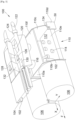
- THE Figs. 3 to 5 show the part of the aircraft 100 where the tanks 106 are arranged. On the
- a portion of the cover 104d has been removed to show the transport pipe 102 in the over-pipe 104.
- the aircraft 100 thus comprises, for each tank 106, a chamber 110 comprising, by side walls 110a-d, here four in number and where each extends generally vertically, a floor 110e and a ceiling 110f.
- the side walls 110a-d, the floor 110e and the ceiling 110f together delimit a sealed volume 112.
- the junction between the side walls 110a-d, the floor 110e and the ceiling 110f are sealed to prevent dihydrogen from a leak in the chamber 110 from diffusing through the aircraft 100.
- systems 114 are arranged and these systems 114 are provided to ensure the transport of dihydrogen from the tank 106 to the transport pipe 102.
- These systems 114 are for example distribution pipes to pumps, heaters, etc. which ensure the treatment of dihydrogen and which are for example arranged in a neighboring dedicated compartment.
- Each transport pipe 102 is fluidically connected to one of the systems 114, such as for example a distribution pipe fluidically connected to a pump and to do this, the ceiling 110f is equipped with a chimney 116 through which the transport pipe 102 joins the over-pipe 104.
- the number of chimneys 116 may vary for example depending on the number of pipes to be passed. In the embodiment of the invention presented here, there are two chimneys 116.
- the aircraft 100 comprises an extraction chamber 120 delimited by walls.
- the chimney 116 and each over-pipe 104 corresponding to a transport pipe 102 passing through the chimney 116 open into the extraction chamber 120, here through orifices in the walls of said extraction chamber 120.
- the or each chimney 116 opens into the extraction chamber 120 from below said extraction chamber 120.
- Each transport pipe 102 thus passes through the chamber 110 and the extraction chamber 120.
- Each chimney 116 is sealed in the sense that it does not allow gas to escape into the interior of the aircraft 100, but it is not sealed in the sense that it guides gas between the chamber 110 and the extraction chamber 120.
- the aircraft 100 also comprises extraction means which are arranged to extract the gases (air, dihydrogen) present in the extraction chamber 120 towards the outside of the aircraft 100 in order to limit the concentration of dihydrogen.
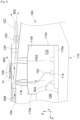
- the extraction system sucks the gases present in the extraction chamber 120 and consequently in the chamber 110 by suction through the chimneys 116 to discharge them outside the aircraft 100.
- the arrows 502 show the path of the gases from the chamber 110 to the outside.
- one of the side walls 110d is made of the skin of the fuselage 50.
- one of the walls of the chamber 110 here the side wall 110a which is towards the front of the aircraft 100 has a passage 121 in which one end of the tank 106 is fixed in a sealed manner.
- Such an arrangement makes it possible to place the line 504 that runs from the reservoir 106 to a system 114 in the chamber 110.
- the line 504 is fluidically connected to the transport line 102 through the systems 114 and thus constitutes a part thereof.
- the aircraft 100 comprises a ventilation system 150 which is arranged here at the upper part of the aircraft 100 at the junction of the wings 52 and which allows the introduction of outside air and the sending of this air in each over-duct 104 towards the extraction chamber 120.
- a ventilation system 150 which is arranged here at the upper part of the aircraft 100 at the junction of the wings 52 and which allows the introduction of outside air and the sending of this air in each over-duct 104 towards the extraction chamber 120.
- the outside air rushes into each over-duct 104 to reach the rear of the over-duct 104 which is here the part which opens into the extraction chamber 120.
- any dihydrogen present in the over-duct 104 is pushed back towards the extraction chamber 120 (arrow 156) where it is evacuated towards the outside of the aircraft 100 by the extraction means.
- the ventilation system 150 takes for example the form of an air vent arranged to capture air from outside the aircraft 100 and arranged for example at the level of the skin of the aircraft 100 and which is therefore open between the exterior of the aircraft 100 and each over-duct 104.
- the extraction chamber 120 is at the rear of the ventilation system 150 and here at the rear of the aircraft 100 and the or each over-duct 104 opens into the extraction chamber 120 via the front of said extraction chamber 120.
- the extraction means comprise a venturi effect system 126, one embodiment of which is shown in Fig. 6 .
- the venturi system 126 comprises a duct 601 with an inlet 602 and an outlet 604 and attached to the exterior of the aircraft 100 and in the exterior airflow with the inlet 602 facing forward and the outlet facing rearward.
- the sheath 601 has a section which decreases between the inlet 602 and an intermediate point 606 between the inlet 602 and the outlet 604 and which increases between the intermediate point 606 and the outlet 604.
- the venturi effect system 126 comprises a transfer pipe 608 which is fluidically connected between the extraction chamber 120 and the sheath 601 and more particularly at the intermediate point 606.
- the flow of external air passing through the duct 601 accelerates between the inlet 602 and the outlet 604 and sucks in the gases present in the extraction chamber 120 through the transfer pipe 608.
- venturi effect system 126 is installed on a roof of the extraction chamber 120.
- the extraction means comprise an evacuation pipe 122 which has a first end which opens outside the aircraft 100 and a second end which is fluidically connected to the extraction chamber 120 and a fan 124 mounted in the evacuation pipe 122.
- the gases present in the extraction chamber 120 are extracted by the fan 124.
- the evacuation pipe 122 opens into the extraction chamber 120 via the rear of said extraction chamber 120.
- the extraction chamber 120 comprises an external wall 128, here its roof, and this external wall 128 is an external wall of the aircraft 100, that is to say in contact with the exterior.
- the external wall 128 is pierced with an opening 130 and is equipped with a hatch 132 movable alternately between a closed position in which the opening 130 is closed and an open position in which the opening 130 is open.
- the hatch 132 is mounted for example on hinges and is locked in the closed position by a latch.
- an air inlet channel 134 is arranged in the lower part of the chamber 110 and it communicates between the exterior of the aircraft 100 and the interior of the chamber 110, here through the side wall 110d forming the skin of the fuselage 50.
Landscapes
- Engineering & Computer Science (AREA)
- Aviation & Aerospace Engineering (AREA)
- Mechanical Engineering (AREA)
- General Engineering & Computer Science (AREA)
- Jet Pumps And Other Pumps (AREA)
- Filling Or Discharging Of Gas Storage Vessels (AREA)
- Pipeline Systems (AREA)
Abstract
Description
- La présente invention se rapporte au domaine des aéronefs et, en particulier, des aéronefs dont la source d'énergie est du dihydrogène liquide ou gazeux que ce soit pour alimenter une pile à combustible ou directement la chambre de combustion d'un moteur. La présente invention concerne ainsi un aéronef comportant une canalisation de transport de dihydrogène et un système d'extraction dudit dihydrogène vers l'extérieur en cas de besoin.
- Il est connu d'utiliser le dihydrogène comme source d'énergie dans un aéronef. Le dihydrogène est stocké dans un réservoir et une canalisation de transport assure le transport du dihydrogène du réservoir vers le dispositif consommateur, comme par exemple une pile à combustible ou la chambre de combustion d'un moteur.
- En cas de fuite de dihydrogène le long de cette canalisation de transport, et pour éviter la création d'un mélange inflammable autour de la zone de fuite, il est nécessaire de prévoir des dispositifs dédiés.
- Les documents
US2024/043843 ,US2023/044493 etUS2023/086167 divulguent des dispositifs de l'art antérieur. - Un objet de la présente invention est de proposer un aéronef comportant une canalisation de transport de dihydrogène et un système d'extraction qui assure l'évacuation du dihydrogène vers l'extérieur de l'aéronef en cas de fuite.
- À cet effet, est proposé un aéronef comportant :
- au moins une canalisation de transport dans laquelle s'écoule du dihydrogène,
- pour chaque canalisation de transport, une sur-canalisation dans laquelle est fixée la canalisation de transport,
- un réservoir contenant du dihydrogène,
- une chambre comportant par des parois latérales, un plancher et un plafond délimitant ensemble un volume étanche et destinée à contenir des systèmes pour le transport du dihydrogène, où ladite au moins une canalisation de transport est fluidiquement connectée à un desdits systèmes, où la ladite au moins une canalisation de transport rejoint la sur-canalisation correspondante à travers une cheminée du plafond,
- une chambre d'extraction dans laquelle débouchent la cheminée et la ou chaque sur-canalisation, et
- des moyens d'extraction arrangés pour extraire les gaz présents dans ladite chambre d'extraction vers l'extérieur.
- Avec un tel arrangement, en cas de fuite de dihydrogène dans la chambre, le dihydrogène est évacué vers l'extérieur de l'aéronef.
- Avantageusement, l'une des parois latérales présente un passage dans lequel une extrémité du réservoir est fixée de manière étanche.
- Avantageusement, la cheminée débouche dans la chambre d'extraction par le dessous de ladite chambre d'extraction.
- Avantageusement, l'aéronef comporte un système d'aération arrangé pour assurer l'introduction d'air extérieur dans la ou chaque sur-canalisation vers la chambre d'extraction. Avantageusement, la ou chaque sur-canalisation débouche dans la chambre d'extraction par l'avant de ladite chambre d'extraction.
- Avantageusement, les moyens d'extraction comportent un système à effet venturi. Avantageusement, les moyens d'extraction comportent une canalisation d'évacuation qui débouche à l'extérieur de l'aéronef et qui est fluidiquement connectée à la chambre d'extraction et un ventilateur monté dans la canalisation d'évacuation.
- Avantageusement, la canalisation d'évacuation débouche dans la chambre d'extraction par l'arrière de ladite chambre d'extraction.
- Avantageusement, la chambre d'extraction comporte une paroi externe constituant une paroi extérieure de l'aéronef, ladite paroi externe est percée d'une ouverture, et ladite paroi externe est équipée d'une trappe mobile alternativement entre une position fermée dans laquelle l'ouverture est fermée et une position ouverte dans laquelle l'ouverture est ouverte. Avantageusement, l'aéronef comporte un canal d'entrée d'air disposé en partie basse de la chambre et communicant entre l'extérieur de l'aéronef et l'intérieur de la chambre.
- Les caractéristiques de l'invention mentionnées ci-dessus, ainsi que d'autres, apparaîtront plus clairement à la lecture de la description suivante d'un exemple de réalisation, ladite description étant faite en relation avec les dessins joints, parmi lesquels :
- [
Fig. 1 ] est une vue de dessus d'un aéronef selon l'invention, - [
Fig. 2 ] est une vue en coupe du fuselage de l'aéronef de laFig. 1 selon la ligne II-II, - [
Fig. 3 ] est une vue en perspective de la partie de l'aéronef comportant un réservoir de dihydrogène, - [
Fig. 4 ] montre la même vue que celle de laFig. 3 sans le réservoir de dihydrogène, - [
Fig. 5 ] est une vue en coupe par un plan vertical de la partie de l'aéronef comportant le réservoir de dihydrogène, et - [
Fig. 6 ] est un agrandissement du détail VI de laFig. 5 . - La
Fig. 1 montre un aéronef 100 qui présente un fuselage 50 de part et d'autre duquel est fixée une aile 52. Sous chaque aile 52 est fixé au moins un système de propulsion 56. - Par convention, on appelle X la direction longitudinale de l'aéronef 100, Y la direction transversale de l'aéronef 100 qui est horizontale lorsque l'aéronef est au sol, et Z la direction verticale ou hauteur verticale lorsque l'aéronef est au sol, ces trois directions X, Y et Z étant orthogonales entre elles.
- D'autre part, les termes " avant " et " arrière " sont à considérer par rapport à une direction d'avancement de l'aéronef 100 lors du fonctionnement des systèmes de propulsion 56, cette direction étant représentée schématiquement par la flèche F.
- Dans le mode de réalisation de l'invention présenté ici, chaque système de propulsion 56 comprend un moteur électrique, une hélice 58 montée sur l'arbre moteur dudit moteur électrique et une pile à combustible qui alimente le moteur en électricité.
- La pile à combustible est alimentée en oxygène et en dihydrogène afin de produire de l'électricité.
- Dans un autre mode de réalisation, le système de propulsion 56 peut prendre la forme d'un turboréacteur dont le carburant qui est brûlé dans la chambre de combustion est du dihydrogène.
- L'aéronef 100 comporte également au moins un réservoir 106 qui est rempli de dihydrogène et il y a ici deux réservoirs 106 disposés respectivement à bâbord et à tribord du fuselage 50.
- Les réservoirs 106 sont disposés ici dans une partie arrière du fuselage 50, mais ils pourraient être disposés dans une autre partie de l'aéronef 100. Le dihydrogène peut être liquide ou gazeux.
- Pour transporter le dihydrogène, l'aéronef 100 comporte au moins une canalisation de transport 102 dans laquelle s'écoule le dihydrogène d'un réservoir 106 vers le système de propulsion 56 pour alimenter une pile à combustible ou une chambre de combustion qui constitue un dispositif consommateur dudit dihydrogène. Pour des raisons de facilité de mise en oeuvre, les canalisations de transport 102 sont préférentiellement disposées en partie haute de l'aéronef 100 et s'étendent ainsi le long du fuselage 50 et des ailes 52 en partie haute de ceux-ci.
- La
Fig. 2 montre une coupe du fuselage 50 avec deux canalisations de transport 102. - Dans le mode de réalisation représenté sur la
Fig. 2 , chaque canalisation de transport 102 est logée et fixée dans une sur-canalisation 104 qui entoure donc ladite canalisation de transport 102. Dans le mode de réalisation de l'invention présenté à laFig. 2 , la sur-canalisation 104 prend la forme d'un caniveau 104a avec un fond 104b, une ouverture 104c à l'opposé du fond 104b, et un couvercle 104d qui recouvre l'ouverture 104c du caniveau 104a en l'obturant. La canalisation de transport 102 est fixée à la sur-canalisation 104 par tous moyens appropriés comme par exemple des colliers. - Dans le mode de réalisation de l'invention présenté à la
Fig. 2 , le caniveau 104a présente une section trapézoïdale, mais des sections de forme différente sont possibles. - Les
Figs. 3 à 5 montrent la partie de l'aéronef 100 où sont disposés les réservoirs 106. Sur la -
Fig. 3 , une partie du couvercle 104d a été retirée pour montrer la canalisation de transport 102 dans la sur-canalisation 104. - L'aéronef 100 comporte ainsi, pour chaque réservoir 106, une chambre 110 comportant par des parois latérales 110a-d, ici au nombre de quatre et où chacune s'étend globalement verticalement, un plancher 110e et un plafond 110f. Les parois latérales 110a-d, le plancher 110e et le plafond 110f délimitent ensemble un volume 112 étanche. La j onction entre les parois latérales 1 10a-d, le plancher 110e et le plafond 110f sont étanches pour éviter que du dihydrogène provenant d'une fuite dans la chambre 110 se diffuse à travers l'aéronef 100. Dans la chambre 110, des systèmes 114 sont agencés et ces systèmes 114 sont prévus pour assurer le transport du dihydrogène du réservoir 106 vers la canalisation de transport 102. Ces systèmes 114 sont par exemple des tuyauteries de distribution vers des pompes, des réchauffeurs, etc qui assurent le traitement du dihydrogène et qui sont par exemple disposés dans un compartiment dédié voisin.
- Chaque canalisation de transport 102 est fluidiquement connectée à un des systèmes 114, comme par exemple une tuyauterie de distribution fluidiquement connectée à une pompe et pour ce faire, le plafond 110f est équipé d'une cheminée 116 à travers laquelle la canalisation de transport 102 rejoint la sur-canalisation 104.
- Le nombre de cheminées 116 peut varier par exemple en fonction du nombre de canalisations à faire passer. Dans le mode de réalisation de l'invention présenté ici, il y a deux cheminées 116.
- Au-dessus du plafond 110f et de chaque cheminée 116, l'aéronef 100 comporte une chambre d'extraction 120 délimitée par des parois. La cheminée 116 et chaque sur-canalisation 104 correspondant à une canalisation de transport 102 traversant la cheminée 116 débouchent dans la chambre d'extraction 120, à travers ici des orifices dans les parois de ladite chambre d'extraction 120.
- Ainsi, dans le mode de réalisation de l'invention présenté aux
Figs. 3 à 5 , la ou chaque cheminée 116 débouche dans la chambre d'extraction 120 par le dessous de ladite chambre d'extraction 120. - Chaque canalisation de transport 102 traverse ainsi la chambre 110 et la chambre d'extraction 120.
- Chaque cheminée 116 est étanche dans le sens où elle ne laisse pas le gaz s'échapper vers l'intérieur de l'aéronef 100, mais elle n'est pas étanche dans le sens où elle guide le gaz entre la chambre 110 et la chambre d'extraction 120.
- L'aéronef 100 comporte également des moyens d'extraction qui sont arrangés pour extraire les gaz (air, dihydrogène) présents dans la chambre d'extraction 120 vers l'extérieur de l'aéronef 100 afin de limiter la concentration de dihydrogène.
- Ainsi, comme le montre la
Fig. 5 , en cas de présence de dihydrogène dans la chambre 110 par exemple du fait d'une fuite d'une canalisation présente dans la chambre 110 ou d'un système 114, le système d'extraction aspire les gaz présents dans la chambre d'extraction 120 et par voie de conséquence dans la chambre 110 par aspiration à travers les cheminées 116 pour les rejeter à l'extérieur de l'aéronef 100. À cette fin, les flèches 502 montrent le parcours des gaz de la chambre 110 vers l'extérieur. - Dans le mode de réalisation de l'invention présenté à la
Fig. 3 , l'une des parois latérales 110d est constituée de la peau du fuselage 50. - Comme le montrent les
Figs. 4 et5 , l'une des parois de la chambre 110, ici la paroi latérale 110a qui est vers l'avant de l'aéronef 100 présente un passage 121 dans lequel une extrémité du réservoir 106 est fixée de manière étanche. Un tel arrangement permet de placer la canalisation 504 qui va du réservoir 106 vers un système 114 dans la chambre 110. La canalisation 504 est fluidiquement connectée à la canalisation de transport 102 à travers les systèmes 114 et en constitue donc une partie. - Dans le mode de réalisation de l'invention présenté à la
Fig. 1 , l'aéronef 100 comporte un système d'aération 150 qui est disposé ici au niveau de la partie supérieure de l'aéronef 100 au niveau de la jonction des ailes 52 et qui permet l'introduction d'air extérieur et l'envoi de cet air dans chaque sur-canalisation 104 vers la chambre d'extraction 120. Ainsi, lorsque l'aéronef 100 avance, l'air extérieur s'engouffre dans chaque sur-canalisation 104 pour rejoindre l'arrière de la sur-canalisation 104 qui est ici la partie qui débouche dans la chambre d'extraction 120. Ainsi, le dihydrogène éventuellement présent dans la sur-canalisation 104 est repoussé vers la chambre d'extraction 120 (flèche 156) où il est évacué vers l'extérieur de l'aéronef 100 par les moyens d'extraction. - Le système d'aération 150 prend par exemple la forme d'une bouche d'aération arrangée pour capter de l'air extérieur à l'aéronef 100 et disposée par exemple au niveau de la peau de l'aéronef 100 et qui est donc ouverte entre l'extérieur de l'aéronef 100 et chaque sur-canalisation 104.
- Du fait que le système d'aération 150 est disposé à l'avant de l'aéronef 100 et pour assurer un bon écoulement de l'air dans chaque sur-canalisation 104, la chambre d'extraction 120 est à l'arrière du système d'aération 150 et ici à l'arrière de l'aéronef 100 et la ou chaque sur-canalisation 104 débouche dans la chambre d'extraction 120 par l'avant de ladite chambre d'extraction 120.
- Dans le mode de réalisation de l'invention présenté aux
Figs. 3 à 5 , les moyens d'extraction comportent un système à effet venturi 126 dont un mode de réalisation est représenté à laFig. 6 . - Le système à effet venturi 126 comporte une gaine 601 avec une entrée 602 et une sortie 604 et fixé sur l'extérieur de l'aéronef 100 et dans le flux d'air extérieur avec l'entrée 602 orientée vers l'avant et la sortie orientée vers l'arrière.
- La gaine 601 présente une section qui diminue entre l'entrée 602 et un point intermédiaire 606 entre l'entrée 602 et la sortie 604 et qui augmente entre le point intermédiaire 606 et la sortie 604.
- Le système à effet venturi 126 comporte une canalisation de transfert 608 qui est fluidiquement connectée entre la chambre d'extraction 120 et la gaine 601 et plus particulièrement au niveau du point intermédiaire 606.
- Ainsi, le flux d'air extérieur passant par la gaine 601 accélère entre l'entrée 602 et la sortie 604 et aspire les gaz présents dans la chambre d'extraction 120 par la canalisation de transfert 608.
- Dans le mode de réalisation de l'invention présenté ici, le système à effet venturi 126 est installé sur un toit de la chambre d'extraction 120.
- En complément, ou en remplacement, les moyens d'extraction comportent une canalisation d'évacuation 122 qui présente une première extrémité qui débouche à l'extérieur de l'aéronef 100 et une deuxième extrémité qui est fluidiquement connectée à la chambre d'extraction 120 et un ventilateur 124 monté dans la canalisation d'évacuation 122. Ainsi, même lorsque l'aéronef 100 est immobile, les gaz présents dans la chambre d'extraction 120 sont extraits par le ventilateur 124.
- Selon un mode de réalisation préférentiel, la canalisation d'évacuation 122 débouche dans la chambre d'extraction 120 par l'arrière de ladite chambre d'extraction 120. Un tel arrangement permet par exemple de profiter de la présence du système d'aération 150 et donc du flux provenant du système d'aération 150, en particulier lorsque la ou chaque sur-canalisation 104 débouche dans la chambre d'extraction 120 par l'avant de ladite chambre d'extraction 120. Dans le mode de réalisation de l'invention présenté aux
Figs. 3 et4 , la chambre d'extraction 120 comporte une paroi externe 128, ici son toit, et cette paroi externe 128 est une paroi extérieure de l'aéronef 100, c'est-à-dire en contact avec l'extérieur. - Pour des raisons d'accès à l'intérieur de la chambre d'extraction 120, la paroi externe 128 est percée d'une ouverture 130 et est équipée d'une trappe 132 mobile alternativement entre une position fermée dans laquelle l'ouverture 130 est fermée et une position ouverte dans laquelle l'ouverture 130 est ouverte. La trappe 132 est montée par exemple sur des charnières et est verrouillée en position fermée par un verrou.
- Selon un mode de réalisation particulier, et pour éviter la mise en dépression de la chambre 110 du fait d'une trop forte aspiration, un canal d'entrée d'air 134 est disposé en partie basse de la chambre 110 et il communique entre l'extérieur de l'aéronef 100 et l'intérieur de la chambre 110, ici à travers la paroi latérale 110d formant la peau du fuselage 50.
Claims (10)
- Aéronef (100) comportant :- au moins une canalisation de transport (102) dans laquelle s'écoule du dihydrogène,- pour chaque canalisation de transport (102), une sur-canalisation (104) dans laquelle est fixée la canalisation de transport (102),- un réservoir (106) contenant du dihydrogène,- une chambre (110) comportant par des parois latérales (110a-d), un plancher (110e) et un plafond (110f) délimitant ensemble un volume (112) étanche et destinée à contenir des systèmes (114) pour le transport du dihydrogène, où ladite au moins une canalisation de transport (102) est fluidiquement connectée à un desdits systèmes (114), où la ladite au moins une canalisation de transport (102) rejoint la sur-canalisation (104) correspondante à travers une cheminée (116) du plafond (110f),- une chambre d'extraction (120) dans laquelle débouchent la cheminée (116) et la ou chaque sur-canalisation (104), et- des moyens d'extraction (122, 124, 126) arrangés pour extraire les gaz présents dans ladite chambre d'extraction (120) vers l'extérieur.
- Aéronef (100) selon la revendication 1, caractérisé en ce que l'une des parois latérales (110a) présente un passage (121) dans lequel une extrémité du réservoir (106) est fixée de manière étanche.
- Aéronef (100) selon l'une des revendications 1 ou 2, caractérisé en ce que la cheminée (116) débouche dans la chambre d'extraction (120) par le dessous de ladite chambre d'extraction (120).
- Aéronef (100) selon l'une des revendications 1 à 3, caractérisé en ce qu'il comporte un système d'aération (150) arrangé pour assurer l'introduction d'air extérieur dans la ou chaque sur-canalisation (104) vers la chambre d'extraction (120).
- Aéronef (100) selon la revendication 4, caractérisé en ce que la ou chaque sur-canalisation (104) débouche dans la chambre d'extraction (120) par l'avant de ladite chambre d'extraction (120).
- Aéronef (100) selon l'une des revendications 4 ou 5, caractérisé en ce que les moyens d'extraction comportent un système à effet venturi (126).
- Aéronef (100) selon l'une des revendications 4 à 6, caractérisé en ce que les moyens d'extraction comportent une canalisation d'évacuation (122) qui débouche à l'extérieur de l'aéronef (100) et qui est fluidiquement connectée à la chambre d'extraction (120) et un ventilateur (124) monté dans la canalisation d'évacuation (122).
- Aéronef (100) selon la revendication 7, caractérisé en ce que la canalisation d'évacuation (122) débouche dans la chambre d'extraction (120) par l'arrière de ladite chambre d'extraction (120).
- Aéronef (100) selon l'une des revendications 1 à 8, caractérisé en ce que la chambre d'extraction (120) comporte une paroi externe (128) constituant une paroi extérieure de l'aéronef (100), en ce que ladite paroi externe (128) est percée d'une ouverture (130), et en ce que ladite paroi externe (128) est équipée d'une trappe (132) mobile alternativement entre une position fermée dans laquelle l'ouverture (130) est fermée et une position ouverte dans laquelle l'ouverture (130) est ouverte.
- Aéronef (100) selon l'une des revendications 1 à 9, caractérisé en ce qu'il comporte un canal d'entrée d'air (134) disposé en partie basse de la chambre (110) et communicant entre l'extérieur de l'aéronef (100) et l'intérieur de la chambre (110).
Applications Claiming Priority (1)
| Application Number | Priority Date | Filing Date | Title |
|---|---|---|---|
| FR2304190A FR3148224A1 (fr) | 2023-04-26 | 2023-04-26 | Aéronef comportant une canalisation de transport de dihydrogène et un système d’extraction dudit dihydrogène vers l’extérieur |
Publications (2)
| Publication Number | Publication Date |
|---|---|
| EP4455022A1 true EP4455022A1 (fr) | 2024-10-30 |
| EP4455022B1 EP4455022B1 (fr) | 2025-06-18 |
Family
ID=87555127
Family Applications (1)
| Application Number | Title | Priority Date | Filing Date |
|---|---|---|---|
| EP24165993.7A Active EP4455022B1 (fr) | 2023-04-26 | 2024-03-25 | Aéronef comportant une canalisation de transport de dihydrogène et un système d'extraction dudit dihydrogène vers l'extérieur |
Country Status (4)
| Country | Link |
|---|---|
| US (1) | US12454366B2 (fr) |
| EP (1) | EP4455022B1 (fr) |
| CN (1) | CN118850345A (fr) |
| FR (1) | FR3148224A1 (fr) |
Families Citing this family (1)
| Publication number | Priority date | Publication date | Assignee | Title |
|---|---|---|---|---|
| US12391398B1 (en) * | 2024-02-05 | 2025-08-19 | The Boeing Company | Fuel jettison system |
Citations (4)
| Publication number | Priority date | Publication date | Assignee | Title |
|---|---|---|---|---|
| US20230043843A1 (en) * | 2021-08-03 | 2023-02-09 | Airbus Sas | Aircraft comprising at least one hydrogen supply device and at least one sealed container, in which at least one item of equipment of said hydrogen supply device is positioned |
| US20230044493A1 (en) | 2021-08-05 | 2023-02-09 | Airbus Sas | Heat exchanger limiting the risk of contamination between two fluids and aircraft comprising at least one such heat exchanger |
| US20230086167A1 (en) | 2021-09-22 | 2023-03-23 | Airbus Sas | Aircraft having a dihydrogen transport pipe and an embedding channel for said transport pipe |
| US20240043843A1 (en) | 2020-12-23 | 2024-02-08 | Ucl Business Ltd | Treatment for lysine degradation-associated disorders |
Family Cites Families (1)
| Publication number | Priority date | Publication date | Assignee | Title |
|---|---|---|---|---|
| DE102010050000B4 (de) * | 2010-11-02 | 2015-02-19 | Airbus Defence and Space GmbH | Kraftstoffleitung in einem Luftfahrzeug |
-
2023
- 2023-04-26 FR FR2304190A patent/FR3148224A1/fr not_active Ceased
-
2024
- 2024-03-25 EP EP24165993.7A patent/EP4455022B1/fr active Active
- 2024-04-05 US US18/627,778 patent/US12454366B2/en active Active
- 2024-04-24 CN CN202410496206.1A patent/CN118850345A/zh active Pending
Patent Citations (4)
| Publication number | Priority date | Publication date | Assignee | Title |
|---|---|---|---|---|
| US20240043843A1 (en) | 2020-12-23 | 2024-02-08 | Ucl Business Ltd | Treatment for lysine degradation-associated disorders |
| US20230043843A1 (en) * | 2021-08-03 | 2023-02-09 | Airbus Sas | Aircraft comprising at least one hydrogen supply device and at least one sealed container, in which at least one item of equipment of said hydrogen supply device is positioned |
| US20230044493A1 (en) | 2021-08-05 | 2023-02-09 | Airbus Sas | Heat exchanger limiting the risk of contamination between two fluids and aircraft comprising at least one such heat exchanger |
| US20230086167A1 (en) | 2021-09-22 | 2023-03-23 | Airbus Sas | Aircraft having a dihydrogen transport pipe and an embedding channel for said transport pipe |
Also Published As
| Publication number | Publication date |
|---|---|
| FR3148224A1 (fr) | 2024-11-01 |
| US12454366B2 (en) | 2025-10-28 |
| EP4455022B1 (fr) | 2025-06-18 |
| CN118850345A (zh) | 2024-10-29 |
| US20240359810A1 (en) | 2024-10-31 |
Similar Documents
| Publication | Publication Date | Title |
|---|---|---|
| EP4124738B1 (fr) | Ensemble propulsif pour aéronef | |
| EP4129827B1 (fr) | Aéronef comprenant au moins un dispositif d alimentation en hydrogène ainsi qu au moins un contenant étanche dans lequel est positionné au moins un équipement dudit dispositif d alimentation en hydrogène | |
| EP4166771B1 (fr) | Ensemble propulsif pour aéronef | |
| EP4455022B1 (fr) | Aéronef comportant une canalisation de transport de dihydrogène et un système d'extraction dudit dihydrogène vers l'extérieur | |
| EP4155213B1 (fr) | Aéronef comportant une canalisation de transport de dihydrogène et un canal d'enfouissement de ladite canalisation de transport | |
| EP3325792B1 (fr) | Ensemble propulsif pour aéronef comportant un inverseur de poussée | |
| FR2808308A1 (fr) | Compresseur a spirale equipe d'un deflecteur en regard de l'orifice d'aspiration menage dans son enveloppe | |
| FR3006999A1 (fr) | Ventilation d'une nacelle de turbomachine | |
| EP4030043B1 (fr) | Ensemble propulsif pour aéronef comportant un système de ventilation et un système anti-incendie | |
| FR3140117A1 (fr) | Aéronef muni d’un moteur et d’un conduit d’échappement drainé autour d’une tuyère d’éjection du moteur | |
| EP4286019B1 (fr) | Aéronef comportant une canalisation de transport de dihydrogène, un canal d'enfouissement de ladite canalisation de transport et un système d'aération dudit canal d'enfouissement | |
| EP4438488B1 (fr) | Ensemble propulsif d'aéronef comportant une nacelle avec un châssis en t | |
| FR3158953A1 (fr) | Ensemble propulsif pour aéronef comportant un ventilateur d’extraction | |
| EP4438487A1 (fr) | Aéronef comportant une canalisation de transport de dihydrogène, un canal d'enfouissement de ladite canalisation de transport et un système d'évacuation de l air et de l eau présente dans ledit canal d'enfouissement | |
| FR2458678A1 (fr) | Collecteur de gaz d'echappement a deux voies, notamment pour lanceurs de fusees | |
| EP4495008B1 (fr) | Nacelle d aéronef comportant un caisson étanche et une porte ouvrant le caisson sur l extérieur | |
| EP4345009B1 (fr) | Ensemble propulsif pour aéronef | |
| FR3153077A1 (fr) | Ensemble propulsif pour aéronef | |
| EP4538513A1 (fr) | Ensemble propulsif pour aéronef | |
| EP4495010A1 (fr) | Module pour aéronef comportant un système de traitement de dihydrogène | |
| EP4435316B1 (fr) | Module pour un système d'alimentation en dihydrogène pour un moteur d'aéronef | |
| EP4293212B1 (fr) | Système de boîtier contenant un échangeur thermique pour réchauffer du dihydrogène | |
| EP4269768B1 (fr) | Ensemble propulsif pour un aéronef | |
| FR3156430A1 (fr) | Ensemble pour la mise à l’air libre d’un volume de dihydrogène gazeux issu d’un dispositif contenant du dihydrogène | |
| EP4474288A1 (fr) | Aéronef muni d'un système de ventilation anti-pluie pour une machine electrique |
Legal Events
| Date | Code | Title | Description |
|---|---|---|---|
| PUAI | Public reference made under article 153(3) epc to a published international application that has entered the european phase |
Free format text: ORIGINAL CODE: 0009012 |
|
| STAA | Information on the status of an ep patent application or granted ep patent |
Free format text: STATUS: REQUEST FOR EXAMINATION WAS MADE |
|
| 17P | Request for examination filed |
Effective date: 20240325 |
|
| AK | Designated contracting states |
Kind code of ref document: A1 Designated state(s): AL AT BE BG CH CY CZ DE DK EE ES FI FR GB GR HR HU IE IS IT LI LT LU LV MC ME MK MT NL NO PL PT RO RS SE SI SK SM TR |
|
| GRAP | Despatch of communication of intention to grant a patent |
Free format text: ORIGINAL CODE: EPIDOSNIGR1 |
|
| STAA | Information on the status of an ep patent application or granted ep patent |
Free format text: STATUS: GRANT OF PATENT IS INTENDED |
|
| RIC1 | Information provided on ipc code assigned before grant |
Ipc: B64D 37/30 20060101ALI20250128BHEP Ipc: B64D 37/32 20060101AFI20250128BHEP |
|
| INTG | Intention to grant announced |
Effective date: 20250213 |
|
| GRAS | Grant fee paid |
Free format text: ORIGINAL CODE: EPIDOSNIGR3 |
|
| GRAA | (expected) grant |
Free format text: ORIGINAL CODE: 0009210 |
|
| STAA | Information on the status of an ep patent application or granted ep patent |
Free format text: STATUS: THE PATENT HAS BEEN GRANTED |
|
| AK | Designated contracting states |
Kind code of ref document: B1 Designated state(s): AL AT BE BG CH CY CZ DE DK EE ES FI FR GB GR HR HU IE IS IT LI LT LU LV MC ME MK MT NL NO PL PT RO RS SE SI SK SM TR |
|
| REG | Reference to a national code |
Ref country code: GB Ref legal event code: FG4D Free format text: NOT ENGLISH |
|
| REG | Reference to a national code |
Ref country code: CH Ref legal event code: EP |
|
| REG | Reference to a national code |
Ref country code: DE Ref legal event code: R096 Ref document number: 602024000208 Country of ref document: DE |
|
| REG | Reference to a national code |
Ref country code: CH Ref legal event code: EP |
|
| REG | Reference to a national code |
Ref country code: IE Ref legal event code: FG4D Free format text: LANGUAGE OF EP DOCUMENT: FRENCH |
|
| PG25 | Lapsed in a contracting state [announced via postgrant information from national office to epo] |
Ref country code: FI Free format text: LAPSE BECAUSE OF FAILURE TO SUBMIT A TRANSLATION OF THE DESCRIPTION OR TO PAY THE FEE WITHIN THE PRESCRIBED TIME-LIMIT Effective date: 20250618 |
|
| REG | Reference to a national code |
Ref country code: LT Ref legal event code: MG9D |
|
| PG25 | Lapsed in a contracting state [announced via postgrant information from national office to epo] |
Ref country code: NO Free format text: LAPSE BECAUSE OF FAILURE TO SUBMIT A TRANSLATION OF THE DESCRIPTION OR TO PAY THE FEE WITHIN THE PRESCRIBED TIME-LIMIT Effective date: 20250918 Ref country code: GR Free format text: LAPSE BECAUSE OF FAILURE TO SUBMIT A TRANSLATION OF THE DESCRIPTION OR TO PAY THE FEE WITHIN THE PRESCRIBED TIME-LIMIT Effective date: 20250919 |
|
| PG25 | Lapsed in a contracting state [announced via postgrant information from national office to epo] |
Ref country code: BG Free format text: LAPSE BECAUSE OF FAILURE TO SUBMIT A TRANSLATION OF THE DESCRIPTION OR TO PAY THE FEE WITHIN THE PRESCRIBED TIME-LIMIT Effective date: 20250618 |
|
| PG25 | Lapsed in a contracting state [announced via postgrant information from national office to epo] |
Ref country code: HR Free format text: LAPSE BECAUSE OF FAILURE TO SUBMIT A TRANSLATION OF THE DESCRIPTION OR TO PAY THE FEE WITHIN THE PRESCRIBED TIME-LIMIT Effective date: 20250618 |
|
| PG25 | Lapsed in a contracting state [announced via postgrant information from national office to epo] |
Ref country code: RS Free format text: LAPSE BECAUSE OF FAILURE TO SUBMIT A TRANSLATION OF THE DESCRIPTION OR TO PAY THE FEE WITHIN THE PRESCRIBED TIME-LIMIT Effective date: 20250918 |
|
| REG | Reference to a national code |
Ref country code: NL Ref legal event code: MP Effective date: 20250618 |
|
| PG25 | Lapsed in a contracting state [announced via postgrant information from national office to epo] |
Ref country code: LV Free format text: LAPSE BECAUSE OF FAILURE TO SUBMIT A TRANSLATION OF THE DESCRIPTION OR TO PAY THE FEE WITHIN THE PRESCRIBED TIME-LIMIT Effective date: 20250618 |
|
| PG25 | Lapsed in a contracting state [announced via postgrant information from national office to epo] |
Ref country code: NL Free format text: LAPSE BECAUSE OF FAILURE TO SUBMIT A TRANSLATION OF THE DESCRIPTION OR TO PAY THE FEE WITHIN THE PRESCRIBED TIME-LIMIT Effective date: 20250618 |
|
| PG25 | Lapsed in a contracting state [announced via postgrant information from national office to epo] |
Ref country code: PT Free format text: LAPSE BECAUSE OF FAILURE TO SUBMIT A TRANSLATION OF THE DESCRIPTION OR TO PAY THE FEE WITHIN THE PRESCRIBED TIME-LIMIT Effective date: 20251020 |
|
| REG | Reference to a national code |
Ref country code: AT Ref legal event code: MK05 Ref document number: 1803998 Country of ref document: AT Kind code of ref document: T Effective date: 20250618 |
|
| PG25 | Lapsed in a contracting state [announced via postgrant information from national office to epo] |
Ref country code: IS Free format text: LAPSE BECAUSE OF FAILURE TO SUBMIT A TRANSLATION OF THE DESCRIPTION OR TO PAY THE FEE WITHIN THE PRESCRIBED TIME-LIMIT Effective date: 20251018 |
|
| PG25 | Lapsed in a contracting state [announced via postgrant information from national office to epo] |
Ref country code: AT Free format text: LAPSE BECAUSE OF FAILURE TO SUBMIT A TRANSLATION OF THE DESCRIPTION OR TO PAY THE FEE WITHIN THE PRESCRIBED TIME-LIMIT Effective date: 20250618 Ref country code: SM Free format text: LAPSE BECAUSE OF FAILURE TO SUBMIT A TRANSLATION OF THE DESCRIPTION OR TO PAY THE FEE WITHIN THE PRESCRIBED TIME-LIMIT Effective date: 20250618 |
|
| PG25 | Lapsed in a contracting state [announced via postgrant information from national office to epo] |
Ref country code: CZ Free format text: LAPSE BECAUSE OF FAILURE TO SUBMIT A TRANSLATION OF THE DESCRIPTION OR TO PAY THE FEE WITHIN THE PRESCRIBED TIME-LIMIT Effective date: 20250618 |
|
| PG25 | Lapsed in a contracting state [announced via postgrant information from national office to epo] |
Ref country code: PL Free format text: LAPSE BECAUSE OF FAILURE TO SUBMIT A TRANSLATION OF THE DESCRIPTION OR TO PAY THE FEE WITHIN THE PRESCRIBED TIME-LIMIT Effective date: 20250618 |
|
| PG25 | Lapsed in a contracting state [announced via postgrant information from national office to epo] |
Ref country code: EE Free format text: LAPSE BECAUSE OF FAILURE TO SUBMIT A TRANSLATION OF THE DESCRIPTION OR TO PAY THE FEE WITHIN THE PRESCRIBED TIME-LIMIT Effective date: 20250618 |
|
| PG25 | Lapsed in a contracting state [announced via postgrant information from national office to epo] |
Ref country code: SK Free format text: LAPSE BECAUSE OF FAILURE TO SUBMIT A TRANSLATION OF THE DESCRIPTION OR TO PAY THE FEE WITHIN THE PRESCRIBED TIME-LIMIT Effective date: 20250618 |
|
| PG25 | Lapsed in a contracting state [announced via postgrant information from national office to epo] |
Ref country code: ES Free format text: LAPSE BECAUSE OF FAILURE TO SUBMIT A TRANSLATION OF THE DESCRIPTION OR TO PAY THE FEE WITHIN THE PRESCRIBED TIME-LIMIT Effective date: 20250618 |
|
| REG | Reference to a national code |
Ref country code: DE Ref legal event code: R097 Ref document number: 602024000208 Country of ref document: DE |
|
| PG25 | Lapsed in a contracting state [announced via postgrant information from national office to epo] |
Ref country code: DK Free format text: LAPSE BECAUSE OF FAILURE TO SUBMIT A TRANSLATION OF THE DESCRIPTION OR TO PAY THE FEE WITHIN THE PRESCRIBED TIME-LIMIT Effective date: 20250618 |
|
| PGFP | Annual fee paid to national office [announced via postgrant information from national office to epo] |
Ref country code: DE Payment date: 20260319 Year of fee payment: 3 |
|
| PG25 | Lapsed in a contracting state [announced via postgrant information from national office to epo] |
Ref country code: IT Free format text: LAPSE BECAUSE OF FAILURE TO SUBMIT A TRANSLATION OF THE DESCRIPTION OR TO PAY THE FEE WITHIN THE PRESCRIBED TIME-LIMIT Effective date: 20250618 |
|
| PGFP | Annual fee paid to national office [announced via postgrant information from national office to epo] |
Ref country code: FR Payment date: 20260323 Year of fee payment: 3 |
|
| PLBE | No opposition filed within time limit |
Free format text: ORIGINAL CODE: 0009261 |
|
| STAA | Information on the status of an ep patent application or granted ep patent |
Free format text: STATUS: NO OPPOSITION FILED WITHIN TIME LIMIT |
|
| REG | Reference to a national code |
Ref country code: CH Ref legal event code: L10 Free format text: ST27 STATUS EVENT CODE: U-0-0-L10-L00 (AS PROVIDED BY THE NATIONAL OFFICE) Effective date: 20260430 |