EP4455020A1 - Device and method for reducing unusable fuel in a tank, e.g. of an aircraft, fuel tank and aircraft - Google Patents
Device and method for reducing unusable fuel in a tank, e.g. of an aircraft, fuel tank and aircraft Download PDFInfo
- Publication number
- EP4455020A1 EP4455020A1 EP23170644.1A EP23170644A EP4455020A1 EP 4455020 A1 EP4455020 A1 EP 4455020A1 EP 23170644 A EP23170644 A EP 23170644A EP 4455020 A1 EP4455020 A1 EP 4455020A1
- Authority
- EP
- European Patent Office
- Prior art keywords
- tank
- fuel
- valve
- overflow pipe
- aircraft
- Prior art date
- Legal status (The legal status is an assumption and is not a legal conclusion. Google has not performed a legal analysis and makes no representation as to the accuracy of the status listed.)
- Granted
Links
Images


Classifications
-
- B—PERFORMING OPERATIONS; TRANSPORTING
- B64—AIRCRAFT; AVIATION; COSMONAUTICS
- B64D—EQUIPMENT FOR FITTING IN OR TO AIRCRAFT; FLIGHT SUITS; PARACHUTES; ARRANGEMENT OR MOUNTING OF POWER PLANTS OR PROPULSION TRANSMISSIONS IN AIRCRAFT
- B64D37/00—Arrangements in connection with fuel supply for power plant
- B64D37/02—Tanks
- B64D37/14—Filling or emptying
- B64D37/20—Emptying systems
- B64D37/22—Emptying systems facilitating emptying in any position of tank
-
- F—MECHANICAL ENGINEERING; LIGHTING; HEATING; WEAPONS; BLASTING
- F02—COMBUSTION ENGINES; HOT-GAS OR COMBUSTION-PRODUCT ENGINE PLANTS
- F02M—SUPPLYING COMBUSTION ENGINES IN GENERAL WITH COMBUSTIBLE MIXTURES OR CONSTITUENTS THEREOF
- F02M37/00—Apparatus or systems for feeding liquid fuel from storage containers to carburettors or fuel-injection apparatus; Arrangements for purifying liquid fuel specially adapted for, or arranged on, internal-combustion engines
- F02M37/0076—Details of the fuel feeding system related to the fuel tank
- F02M37/0088—Multiple separate fuel tanks or tanks being at least partially partitioned
- F02M37/0094—Saddle tanks; Tanks having partition walls
-
- B—PERFORMING OPERATIONS; TRANSPORTING
- B64—AIRCRAFT; AVIATION; COSMONAUTICS
- B64D—EQUIPMENT FOR FITTING IN OR TO AIRCRAFT; FLIGHT SUITS; PARACHUTES; ARRANGEMENT OR MOUNTING OF POWER PLANTS OR PROPULSION TRANSMISSIONS IN AIRCRAFT
- B64D37/00—Arrangements in connection with fuel supply for power plant
- B64D37/02—Tanks
- B64D37/06—Constructional adaptations thereof
- B64D37/08—Internal partitioning
-
- B—PERFORMING OPERATIONS; TRANSPORTING
- B64—AIRCRAFT; AVIATION; COSMONAUTICS
- B64D—EQUIPMENT FOR FITTING IN OR TO AIRCRAFT; FLIGHT SUITS; PARACHUTES; ARRANGEMENT OR MOUNTING OF POWER PLANTS OR PROPULSION TRANSMISSIONS IN AIRCRAFT
- B64D37/00—Arrangements in connection with fuel supply for power plant
- B64D37/02—Tanks
- B64D37/14—Filling or emptying
-
- Y—GENERAL TAGGING OF NEW TECHNOLOGICAL DEVELOPMENTS; GENERAL TAGGING OF CROSS-SECTIONAL TECHNOLOGIES SPANNING OVER SEVERAL SECTIONS OF THE IPC; TECHNICAL SUBJECTS COVERED BY FORMER USPC CROSS-REFERENCE ART COLLECTIONS [XRACs] AND DIGESTS
- Y02—TECHNOLOGIES OR APPLICATIONS FOR MITIGATION OR ADAPTATION AGAINST CLIMATE CHANGE
- Y02T—CLIMATE CHANGE MITIGATION TECHNOLOGIES RELATED TO TRANSPORTATION
- Y02T50/00—Aeronautics or air transport
- Y02T50/40—Weight reduction
Definitions
- the invention relates to a device and to a method for reducing unusable fuel in a tank, preferably of an aircraft. Further, the invention relates to a fuel tank for an aircraft and to an aircraft.
- Residuals of fuels in aircraft fuel tanks may cause a growth of microorganisms within the tank, which can block the flow of fuel and cause corrosion, thus affecting both safety and maintenance costs.
- the intrinsic water content of fuel and atmospheric moisture condensation on fuel tank walls help microbes to flourish. Therefore, a current treatment of the tank is necessary, involving periodic removal of water, cleaning of the tank and the addition of chemicals to the fuel. However, this is costly and not always effective enough.
- elevations are formed at the bottom of the tank which divide the bottom into several bays, in which residuals remain when the tank is emptied.
- passages may be provided within or between the elevations or walls which separate the different bays from each other.
- such passages within or between the elevations cannot be realized in all types of aircraft tanks.
- the elevations at the bottom of the tank are formed by structural parts of the aircraft like e.g. stringers which do not allow the provision of fuel passages.
- a liner inside the tank.
- the liner shall reduce the fuel flow after a structural impact.
- the liner covers the inner side of the bottom wall of the tank formed by the structure including the elevations, and thus leads to a conglomeration of unused fuel in particular in the lower centre area of the tank.
- Such a tank may be for example a rear centre tank of an aircraft.
- the unused residual fuel remaining in certain areas of the tank causes several disadvantages: First, there is an increased risk of kerosene fungus in the tank. This is even more critical for biofuels called sustainable aviation fuel (SAF) generated by biomass. Secondly, it causes a weight penalty due to an unusable remaining fuel portion, which might by e.g. around 60 to 100 kg or even more. Further, it might increase a risk of not fulfilling requirements dealing with maximum volume of remaining fuel for an empty tank. In addition, it causes a reduced tank capacity of fuel which can be used for propelling the aircraft.
- SAF sustainable aviation fuel
- the invention provides a device for reducing unusable fuel in a tank of an aircraft, wherein the bottom of the tank is divided into at least two adjacent bays by at least one separation wall, the device comprising: an overflow pipe configured to be mounted in the tank so that it extends from the bottom of one bay across the separation wall to the bottom of the other bay, and a valve provided in an opening located in an upper section of the overflow pipe, the valve being configured to automatically open when the tank is filled with fuel and to automatically close when the fuel is extracted from the tank.
- the valve is configured to automatically open when the fuel pressure in the tank reaches a predefined level to release air from the overflow pipe, and to automatically close when the air has completely left the overflow pipe.
- the valve comprises a ball for opening and closing the valve, wherein the ball is lifted to open the valve by the pressure of the air within the overflow pipe and lowered to close the valve when the overflow pipe is completely filled with fuel.
- the valve comprises a spring acting on the ball to additionally support closing the valve.
- the device comprises a fixation member configured for fastening the device to the separation wall so that the ends of the overflow pipe are positioned close to the bottoms of the adjacent bays and the opening provided in the upper section of the overflow pipe is positioned at a higher level than the separation wall.
- overflow pipes with valves are used per bay to provide redundancy.
- Preferably several bays are connected in series.
- the overflow pipe is made of a fuel resistant material. It can be made of metal, but it is preferably made as a plastic injection molding part.
- the valve comprises a valve head that is checkable and repairable.
- the valve head may be comprised by an upper end of the overflow pipe.
- the valve is designed in such a way that when the tank is filled, it opens automatically when the fuel pressure reaches a certain level.
- the overflow pipe forms a bridge between its both ends.
- the position of the bridge and its design take into account the specific aircraft.
- flight conditions as e.g. climb or descent can be considered in the design.
- the invention provides a method for reducing unusable fuel in a tank, preferably of an aircraft, wherein the bottom of the tank is divided into at least two adjacent bays by at least one separation wall, the method comprising: providing an overflow pipe between two adjacent bays which extends from the bottom of one bay across the separation wall to the bottom of the other bay; completely filling the overflow pipe with fuel when the tank is filled with fuel by automatic opening of a valve connected to an upper opening of the overflow pipe; allowing an overflow of fuel across the separation wall by automatic closing of the valve before or when the fuel is extracted from the tank.
- the overflow of fuel across the separation wall is driven by the hydrostatic paradox.
- the valve is closed during the fuel extraction.
- the air is preferably released from the overflow pipe so that the bridge which is formed by a centre portion of the overflow pipe is completely filled with fuel.
- the invention provides a fuel tank, preferably for an aircraft, the tank comprising a bottom which is divided into at least two adjacent bays by at least one separation wall, and a device according to the invention.
- the tank is formed by a structure of an aircraft, wherein the bottom of the tank is formed by a protective liner covering the structure.
- the structure is a fuselage structure.
- the invention provides an aircraft comprising a fuel tank according to the invention.
- the weight of the aircraft is reduced and kerosene fungus is avoided.
- the invention provides an extended flight range. Moreover, no additional technology is needed, like e.g. pumps or similar, and thus the costs are minimized.
- the invention solves the objective by reducing the volume of unusable fuel within the tank.
- the overflow pipe with the valve ensures that this volume remains extremely small and that the available tank volume can be fully used.
- the risk of kerosene fungus within the tank is reduced.
- weight penalty due to unusable remaining fuel in the tank is avoided.
- the net tank capacity is increased.
- a risk of not fulfilling any requirements dealing with maximum volume of remaining fuel for an empty tank is avoided.
- Characteristics and advantages described herein in relation to the device according to the invention are also related to the method according to the invention and to the fuel tank according to the invention.
- Fig. 1 shows a device 10 for reducing unusable fuel in a tank 11 of an aircraft.
- Tank 11 is only schematically indicated by a dotted line.
- the bottom 12 of tank 11 is divided into a number of adjacent bays 13, 14 by one or more elevations 15 which form separation walls. Each elevation or separation wall 15 may prevent a flow of fuel 16 between the bays 13, 14.
- the device 10 comprises an overflow pipe 17 which is mounted in tank 11.
- the overflow pipe 17 extends from the bottom 18 of bay 13 across the elevation 15 to the bottom 19 of bay 14 which is arranged adjacent to bay 13 and separated from bay 13 by the elevation 15. Both ends 20 of pipe 17 are open and positioned close to the respective bay bottom 18, 19 to allow the fuel 16 at the bottom 18, 19 to flow into the pipe and out of the pipe.
- the overflow pipe 17 comprises an opening 21 which is located in an upper end section 22 of overflow pipe 17.
- the opening 21 is connected to a valve 23 which is configured to automatically open when tank 11 is filled with fuel 16 and to automatically close when the fuel 16 is extracted from tank 11.
- the overflow pipe 17 is preferably produced by 3D printing or injection molding technology. It may be made of thermoplastic material or of a metal. The diameter of pipe 17 ensures a sufficient amount of flow from one bay to another.
- bottom 12 of tank 11 is formed by a liner 26 which covers a primary structure 27 of the aircraft which forms tank 11.
- Liner 26 together with the underlying primary structure 27 forms the elevation 15 between the bays 13, 14.
- the valve 23 is preferably designed as a ball valve comprising a ball 29. As an option, it may additionally comprise a spring.
- a fixation member 35 is provided which allows the pipe 17 to be attached to the aircraft structure.
- the fixation member 35 is for example designed as a bracket.
- An inspection and maintenance screw 30 is provided on device 10 to open it in order to open the valve 23 for inspection and/or maintenance work.
- the upper end section 22 of the overflow pipe 17 comprises a valve head that is checkable and repairable.
- valve 23 automatically opens due to the pressure of the fuel 16 in tank 11 when the fuel level 24 is above opening 21. As a consequence, air 25 within pipe 17 is released from overflow pipe 17.
- the fuel level 24 Due to further filling of the tank 11, the fuel level 24 has increased.
- the increased pressure of air bubble 25 within tube or pipe 17 causes opening of valve 23.
- the opening pressure is for example 0.05 to 0.08 bar.
- the air 25 is released as an airflow through the open valve 23 until the air 25 completely left the overflow valve 23.
- the fluid level 28 inside the tube or overflow pipe 17 increases until the tube 17 is completely filled with fuel.
- the valve 23 closes automatically, since there is no pressure any more within tube 17 which causes the valve to be open.
- Fig. 3 shows the state of the device 10 inside fuel tank 11 when the overflow pipe 17 is filled completely with fuel 16 and the valve 23 is closed.
- the fuel level 24 decreases and reaches a level below the elevation or separation wall 15
- the fuel 16 can flow from one bay to the other through overflow pipe 17 over the elevation 15 for balancing the fuel levels in both adjacent bays 13, 14. In this way, the fuel levels in both bays 13, 14 remain equal until both bays 13, 14 are completely emptied.
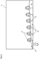
- Fig. 4 shows a section of tank 11 having a number of adjacent bays 33 separated by elevations 15 formed on tank bottom 12, wherein on each elevation 15 an overflow pipe 17 is provided as described above. In this way several bays 33 are connected in series.
- the overflow pipes 17 are designed to work according to the hydrostatic paradox of tolerance which enables a fuel overflow 31 from one bay to the next.
- the valves 23 are closed when the fuel 16 is extracted from the tank 11.
- Fig. 5 shows tank 11 when it is emptied through a fuel extraction bay 34 provided at the tank bottom, as indicated by arrow F.
- the plurality of bays 33 are provided at bottom 12 of tank 11 by separation walls 15.
- the different fuel levels due to fuel extraction are balanced by the devices 10 as described above (see Fig. 4 ).
- the bays 33, 34 are connected in series by the devices 10. The pressure compensation between the bay 34 from which the fuel is taken and the bay 33 next to it results in fuel overflow 31 between the bays with a higher fuel level and the bays with a lower fuel level.
- the fuel 16 is transferred from one bay to the next according to the hydrostatic paradox of tolerance.
- the overflow pipes 17 form bridges over the separation walls 15
Landscapes
- Engineering & Computer Science (AREA)
- Chemical & Material Sciences (AREA)
- Combustion & Propulsion (AREA)
- Mechanical Engineering (AREA)
- General Engineering & Computer Science (AREA)
- Aviation & Aerospace Engineering (AREA)
- Cooling, Air Intake And Gas Exhaust, And Fuel Tank Arrangements In Propulsion Units (AREA)
Abstract
Description
- The invention relates to a device and to a method for reducing unusable fuel in a tank, preferably of an aircraft. Further, the invention relates to a fuel tank for an aircraft and to an aircraft.
- Residuals of fuels in aircraft fuel tanks may cause a growth of microorganisms within the tank, which can block the flow of fuel and cause corrosion, thus affecting both safety and maintenance costs. The intrinsic water content of fuel and atmospheric moisture condensation on fuel tank walls help microbes to flourish. Therefore, a current treatment of the tank is necessary, involving periodic removal of water, cleaning of the tank and the addition of chemicals to the fuel. However, this is costly and not always effective enough.
- In addition, in many aircraft tanks elevations are formed at the bottom of the tank which divide the bottom into several bays, in which residuals remain when the tank is emptied. To allow a uniform drainage of the tank, passages may be provided within or between the elevations or walls which separate the different bays from each other. However, such passages within or between the elevations cannot be realized in all types of aircraft tanks. In particular in aircraft tanks which are formed by the fuselage structure of the aircraft, or which are part of the aircraft structure, the elevations at the bottom of the tank are formed by structural parts of the aircraft like e.g. stringers which do not allow the provision of fuel passages.
- In particular fuel tanks which are formed by the lower fuselage structure need to be protected by a liner inside the tank. The liner shall reduce the fuel flow after a structural impact. The liner covers the inner side of the bottom wall of the tank formed by the structure including the elevations, and thus leads to a conglomeration of unused fuel in particular in the lower centre area of the tank.
- Such a tank may be for example a rear centre tank of an aircraft.
- The unused residual fuel remaining in certain areas of the tank causes several disadvantages: First, there is an increased risk of kerosene fungus in the tank. This is even more critical for biofuels called sustainable aviation fuel (SAF) generated by biomass. Secondly, it causes a weight penalty due to an unusable remaining fuel portion, which might by e.g. around 60 to 100 kg or even more. Further, it might increase a risk of not fulfilling requirements dealing with maximum volume of remaining fuel for an empty tank. In addition, it causes a reduced tank capacity of fuel which can be used for propelling the aircraft.
- It is the objective of the invention to reduce the weight of the aircraft and to reduce the risk of kerosene fungus in aircraft tanks.
- According to a first aspect of, the invention provides a device for reducing unusable fuel in a tank of an aircraft, wherein the bottom of the tank is divided into at least two adjacent bays by at least one separation wall, the device comprising: an overflow pipe configured to be mounted in the tank so that it extends from the bottom of one bay across the separation wall to the bottom of the other bay, and a valve provided in an opening located in an upper section of the overflow pipe, the valve being configured to automatically open when the tank is filled with fuel and to automatically close when the fuel is extracted from the tank.
- Preferably, the valve is configured to automatically open when the fuel pressure in the tank reaches a predefined level to release air from the overflow pipe, and to automatically close when the air has completely left the overflow pipe.
- Preferably, the valve comprises a ball for opening and closing the valve, wherein the ball is lifted to open the valve by the pressure of the air within the overflow pipe and lowered to close the valve when the overflow pipe is completely filled with fuel.
- Preferably, the valve comprises a spring acting on the ball to additionally support closing the valve.
- Preferably, the device comprises a fixation member configured for fastening the device to the separation wall so that the ends of the overflow pipe are positioned close to the bottoms of the adjacent bays and the opening provided in the upper section of the overflow pipe is positioned at a higher level than the separation wall.
- Preferably two overflow pipes with valves are used per bay to provide redundancy. Preferably several bays are connected in series.
- Preferably the overflow pipe is made of a fuel resistant material. It can be made of metal, but it is preferably made as a plastic injection molding part.
- Preferably, the valve comprises a valve head that is checkable and repairable. The valve head may be comprised by an upper end of the overflow pipe.
- Preferably, the valve is designed in such a way that when the tank is filled, it opens automatically when the fuel pressure reaches a certain level.
- Preferably, the overflow pipe forms a bridge between its both ends. Preferably, the position of the bridge and its design take into account the specific aircraft. Moreover, flight conditions as e.g. climb or descent can be considered in the design.
- According to a second aspect, the invention provides a method for reducing unusable fuel in a tank, preferably of an aircraft, wherein the bottom of the tank is divided into at least two adjacent bays by at least one separation wall, the method comprising: providing an overflow pipe between two adjacent bays which extends from the bottom of one bay across the separation wall to the bottom of the other bay; completely filling the overflow pipe with fuel when the tank is filled with fuel by automatic opening of a valve connected to an upper opening of the overflow pipe; allowing an overflow of fuel across the separation wall by automatic closing of the valve before or when the fuel is extracted from the tank.
- Preferably, the overflow of fuel across the separation wall is driven by the hydrostatic paradox.
- Preferably, the valve is closed during the fuel extraction.
- For fuel extraction, the air is preferably released from the overflow pipe so that the bridge which is formed by a centre portion of the overflow pipe is completely filled with fuel.
- According to a third aspect, the invention provides a fuel tank, preferably for an aircraft, the tank comprising a bottom which is divided into at least two adjacent bays by at least one separation wall, and a device according to the invention.
- Preferably, the tank is formed by a structure of an aircraft, wherein the bottom of the tank is formed by a protective liner covering the structure.
- Preferably, the structure is a fuselage structure.
- According to a fourth aspect, the invention provides an aircraft comprising a fuel tank according to the invention.
- By the invention, the weight of the aircraft is reduced and kerosene fungus is avoided. The invention provides an extended flight range. Moreover, no additional technology is needed, like e.g. pumps or similar, and thus the costs are minimized.
- The invention solves the objective by reducing the volume of unusable fuel within the tank. The overflow pipe with the valve ensures that this volume remains extremely small and that the available tank volume can be fully used. As a result, the risk of kerosene fungus within the tank is reduced. In addition, weight penalty due to unusable remaining fuel in the tank is avoided. Further, the net tank capacity is increased. Moreover, a risk of not fulfilling any requirements dealing with maximum volume of remaining fuel for an empty tank is avoided.
- Characteristics and advantages described herein in relation to the device according to the invention are also related to the method according to the invention and to the fuel tank according to the invention.
- In the following, exemplary embodiments of the invention showing further characteristics and advantages are described in detail with reference to the figures, in which:
- Fig. 1
- shows a cross sectional view of a device according to a preferred embodiment of the invention, together with a section of the bottom of an aircraft tank in which it is installed;
- Fig. 2
- shows the device depicted in
figure 1 in a similar view during tank filling; - Fig. 3
- shows the device as depicted in
figure 1 when fuel is extracted from the tank; - Fig. 4
- shows a portion of the bottom of an aircraft tank comprising several bays equipped with devices as shown in the previous figures; and
- Fig. 5
- schematically shows an aircraft tank equipped with a number of devices as shown in the previous figures, wherein the fuel flows from one bay to the next when emptying the tank.
-
Fig. 1 shows adevice 10 for reducing unusable fuel in atank 11 of an aircraft.Tank 11 is only schematically indicated by a dotted line. The bottom 12 oftank 11 is divided into a number ofadjacent bays more elevations 15 which form separation walls. Each elevation orseparation wall 15 may prevent a flow offuel 16 between thebays device 10 comprises anoverflow pipe 17 which is mounted intank 11. - The
overflow pipe 17 extends from the bottom 18 ofbay 13 across theelevation 15 to the bottom 19 ofbay 14 which is arranged adjacent tobay 13 and separated frombay 13 by theelevation 15. Both ends 20 ofpipe 17 are open and positioned close to the respective bay bottom 18, 19 to allow thefuel 16 at the bottom 18, 19 to flow into the pipe and out of the pipe. Theoverflow pipe 17 comprises anopening 21 which is located in anupper end section 22 ofoverflow pipe 17. Theopening 21 is connected to avalve 23 which is configured to automatically open whentank 11 is filled withfuel 16 and to automatically close when thefuel 16 is extracted fromtank 11. - The
overflow pipe 17 is preferably produced by 3D printing or injection molding technology. It may be made of thermoplastic material or of a metal. The diameter ofpipe 17 ensures a sufficient amount of flow from one bay to another. - In this embodiment, bottom 12 of
tank 11 is formed by aliner 26 which covers aprimary structure 27 of the aircraft which formstank 11.Liner 26 together with the underlyingprimary structure 27 forms theelevation 15 between thebays - The
valve 23 is preferably designed as a ball valve comprising aball 29. As an option, it may additionally comprise a spring. Afixation member 35 is provided which allows thepipe 17 to be attached to the aircraft structure. Thefixation member 35 is for example designed as a bracket. - An inspection and
maintenance screw 30 is provided ondevice 10 to open it in order to open thevalve 23 for inspection and/or maintenance work. Theupper end section 22 of theoverflow pipe 17 comprises a valve head that is checkable and repairable. - When
fuel 16 is filled into theempty tank 11, thefuel level 24 intank 11 increases aboveelevation 15 and bothadjacent bays fuel 16. Sincevalve 23 is still closed, as shown infigure 1 , theoverflow pipe 17 is mainly still filled withair 25 forming an air bubble, and thelevel 28 of the fuel inside the overflow pipe ortube 17 is still very low compared to thefuel level 24 outside the tube orpipe 17. In this state, no fuel overflow within theoverflow pipe 17 is possible. - As shown in
Fig. 2 ,valve 23 automatically opens due to the pressure of thefuel 16 intank 11 when thefuel level 24 is aboveopening 21. As a consequence,air 25 withinpipe 17 is released fromoverflow pipe 17. - Due to further filling of the
tank 11, thefuel level 24 has increased. The increased pressure ofair bubble 25 within tube orpipe 17 causes opening ofvalve 23. The opening pressure is for example 0.05 to 0.08 bar. Theair 25 is released as an airflow through theopen valve 23 until theair 25 completely left theoverflow valve 23. Thefluid level 28 inside the tube oroverflow pipe 17 increases until thetube 17 is completely filled with fuel. When thefuel level 24 is above theopening 21, thevalve 23 closes automatically, since there is no pressure any more withintube 17 which causes the valve to be open. -
Fig. 3 shows the state of thedevice 10 insidefuel tank 11 when theoverflow pipe 17 is filled completely withfuel 16 and thevalve 23 is closed. When thefuel level 24 decreases and reaches a level below the elevation orseparation wall 15, thefuel 16 can flow from one bay to the other throughoverflow pipe 17 over theelevation 15 for balancing the fuel levels in bothadjacent bays bays bays -
Fig. 4 shows a section oftank 11 having a number ofadjacent bays 33 separated byelevations 15 formed ontank bottom 12, wherein on eachelevation 15 anoverflow pipe 17 is provided as described above. In this wayseveral bays 33 are connected in series. Theoverflow pipes 17 are designed to work according to the hydrostatic paradox of tolerance which enables afuel overflow 31 from one bay to the next. For this purpose, thevalves 23 are closed when thefuel 16 is extracted from thetank 11. -
Fig. 5 showstank 11 when it is emptied through afuel extraction bay 34 provided at the tank bottom, as indicated by arrow F. The plurality ofbays 33 are provided atbottom 12 oftank 11 byseparation walls 15. The different fuel levels due to fuel extraction are balanced by thedevices 10 as described above (seeFig. 4 ). As described with reference tofigure 4 , thebays devices 10. The pressure compensation between thebay 34 from which the fuel is taken and thebay 33 next to it results infuel overflow 31 between the bays with a higher fuel level and the bays with a lower fuel level. - Thus, the
fuel 16 is transferred from one bay to the next according to the hydrostatic paradox of tolerance. Theoverflow pipes 17 form bridges over theseparation walls 15 - The features and characteristics described above as examples with reference to
figure 1 and the following figures apply in the same manner to all figures. In the figures, identical reference numbers are used for similar or identical parts. -
- 10
- device
- 11
- tank
- 12
- bottom of tank
- 13, 14
- bays
- 15
- elevations / separation walls
- 16
- fuel
- 17
- overflow pipe
- 18
- bottom of bay
- 19
- bottom of bay
- 20
- ends of overflow pipe
- 21
- opening
- 22
- upper end section of overflow pipe
- 23
- valve
- 24
- fuel level in the tank
- 25
- air
- 26
- liner
- 27
- primary structure
- 28
- fuel level inside overflow pipe
- 29
- ball
- 30
- screw
- 31
- fuel over flow
- 33
- plurality of adjacent bays
- 34
- fuel extraction bay
- 35
- fixation member
- F
- Fuel extraction
Claims (10)
- Device for reducing unusable fuel in a tank, preferably of an aircraft, wherein the bottom (12) of the tank (11) is divided into at least two adjacent bays (13, 14, 33) by at least one separation wall (15), the device (10) comprising:an overflow pipe (17) configured to be mounted in the tank (11) so that it extends from the bottom (18) of one bay (13, 33) across the separation wall (15) to the bottom (19) of the other bay (14, 33),and a valve (23) provided in an opening (21) located in an upper section (22) of the overflow pipe (17),the valve (23) being configured to automatically open when the tank (11) is filled with fuel (16) and to automatically close when the fuel (16) is extracted from the tank (11).
- Device according to claim 1, characterized in that the valve (23) is configured to automatically open when the fuel pressure in the tank (11) reaches a predefined level to release air (25) from the overflow pipe (17), and to automatically close when the air (25) has completely left the overflow pipe (17).
- Device according to claim 1 or 2, characterized in that the valve (23) comprises a ball (29) for opening and closing the valve (23), wherein the ball (29) is lifted to open the valve (23) by the pressure of the air (25) within the overflow pipe (17) and lowered to close the valve (23) when the overflow pipe (17) is completely filled with fuel (16).
- Device according to claim 3, characterized in that the valve (23) comprises a spring acting on the ball (29) to additionally support closing the valve (23).
- Device according to one of the preceding claims, characterized by a fixation member (35) configured for fastening the device (10) to the separation wall (15) so that the ends (20) of the overflow pipe (17) are positioned close to the bottoms (18, 19) of the adjacent bays (13, 14, 33) and the opening (21) provided in the upper section (22) of the overflow pipe (17) is positioned at a higher level than the separation wall (15).
- Method for reducing unusable fuel in a tank, preferably of an aircraft, wherein the bottom (12) of the tank (11) is divided into at least two adjacent bays (18, 19, 33) by at least one separation wall (15), the method comprising:providing an overflow pipe (17) between two adjacent bays (18, 19, 33) which extends from the bottom (18, 19) of one bay (13, 14, 33) across the separation wall (15) to the bottom (18, 19) of the other bay (18, 19, 33);completely filling the overflow pipe (17) with fuel (16) when the tank (11) is filled with fuel (16) by automatic opening of a valve (23) connected to an upper opening (21) of the overflow pipe (17);allowing an overflow (31) of fuel (16) across the separation wall (15) by automatic closing of the valve (23) before or when the fuel (16) is extracted from the tank (11).
- Method according to claim 6, characterized in that the overflow (31) of fuel (16) across the separation wall (15) is driven by the hydrostatic paradox.
- Fuel tank, preferably for an aircraft, comprising a bottom (12) which is divided into at least two adjacent bays (13, 14, 33) by at least one separation wall (15), and a device (10) according to one of claims 1 to 5.
- Fuel tank according to claim 8, characterized in that the tank (11) is formed by a structure (27) of an aircraft, wherein the bottom (12) of the tank (11) is formed by a protective liner (21) covering the aircraft structure (27).
- Aircraft, comprising a fuel tank according to claim 8 or 9.
Priority Applications (1)
| Application Number | Priority Date | Filing Date | Title |
|---|---|---|---|
| EP23170644.1A EP4455020B1 (en) | 2023-04-28 | 2023-04-28 | Device and method for reducing unusable fuel in a tank, e.g. of an aircraft, fuel tank and aircraft |
Applications Claiming Priority (1)
| Application Number | Priority Date | Filing Date | Title |
|---|---|---|---|
| EP23170644.1A EP4455020B1 (en) | 2023-04-28 | 2023-04-28 | Device and method for reducing unusable fuel in a tank, e.g. of an aircraft, fuel tank and aircraft |
Publications (2)
| Publication Number | Publication Date |
|---|---|
| EP4455020A1 true EP4455020A1 (en) | 2024-10-30 |
| EP4455020B1 EP4455020B1 (en) | 2026-03-11 |
Family
ID=86282492
Family Applications (1)
| Application Number | Title | Priority Date | Filing Date |
|---|---|---|---|
| EP23170644.1A Active EP4455020B1 (en) | 2023-04-28 | 2023-04-28 | Device and method for reducing unusable fuel in a tank, e.g. of an aircraft, fuel tank and aircraft |
Country Status (1)
| Country | Link |
|---|---|
| EP (1) | EP4455020B1 (en) |
Citations (3)
| Publication number | Priority date | Publication date | Assignee | Title |
|---|---|---|---|---|
| US4703771A (en) * | 1985-09-13 | 1987-11-03 | Toyota Jidosha Kabushiki Kaisha | Vehicle fuel tank |
| GB2295362A (en) * | 1994-11-22 | 1996-05-29 | Ford Motor Co | Vehicle fuel tank arrangement with syphon tube |
| US20050178880A1 (en) * | 2004-01-29 | 2005-08-18 | Howe Mark E. | Auxiliary fuel tank systems for aircraft and methods for their manufacture and use |
-
2023
- 2023-04-28 EP EP23170644.1A patent/EP4455020B1/en active Active
Patent Citations (3)
| Publication number | Priority date | Publication date | Assignee | Title |
|---|---|---|---|---|
| US4703771A (en) * | 1985-09-13 | 1987-11-03 | Toyota Jidosha Kabushiki Kaisha | Vehicle fuel tank |
| GB2295362A (en) * | 1994-11-22 | 1996-05-29 | Ford Motor Co | Vehicle fuel tank arrangement with syphon tube |
| US20050178880A1 (en) * | 2004-01-29 | 2005-08-18 | Howe Mark E. | Auxiliary fuel tank systems for aircraft and methods for their manufacture and use |
Also Published As
| Publication number | Publication date |
|---|---|
| EP4455020B1 (en) | 2026-03-11 |
Similar Documents
| Publication | Publication Date | Title |
|---|---|---|
| EP1591359A1 (en) | Aircraft and fuel venting system therefor | |
| CN102137788A (en) | Floating oil storage system and method | |
| WO2007139674A2 (en) | Storage tank with self-draining full-contact floating roof | |
| HU224107B1 (en) | Apparatus and method for use with a container for storing a substance | |
| US8486261B2 (en) | Fuel scavenge water removal system | |
| US5445097A (en) | Tanker for the prevention of cargo oil spillage | |
| EP4455020B1 (en) | Device and method for reducing unusable fuel in a tank, e.g. of an aircraft, fuel tank and aircraft | |
| US4051030A (en) | Liquids separating system | |
| US1732222A (en) | Method of and apparatus for separating ground water from petroleum | |
| US2637513A (en) | Aircraft tank arrangement | |
| US2851193A (en) | Means of controlling the emptying of tanks containing liquids of different density | |
| US4580592A (en) | Float controlled separator valve | |
| US4547149A (en) | System for preventing liquids from being driven to the flair stack tip | |
| US20240417238A1 (en) | Liquid Loading Assembly for Filling a Ship-Hold or Tank | |
| US3016912A (en) | Vented liquid storage tank with priority system of supply | |
| US2028755A (en) | Breather valve | |
| US2108945A (en) | Storage tank for liquids | |
| GB2309767A (en) | Damped float valve | |
| GB2123090A (en) | Preventing air locks interupting flow in liquid fuel feed systems in aeronautical engines | |
| KR101295663B1 (en) | Ship mounted with settling tank for oil-water segregation | |
| CN111452908A (en) | Ship and fuel system thereof | |
| US2422869A (en) | Gaging and sampling apparatus for liquid storage tanks | |
| NO336153B1 (en) | Installation for obtaining a pollutant fluid in at least one cross-section of the tanks of a sunken vessel | |
| AU2002215136A1 (en) | Air release valve | |
| US20140283920A1 (en) | Tank provided with an over-pressure valve |
Legal Events
| Date | Code | Title | Description |
|---|---|---|---|
| PUAI | Public reference made under article 153(3) epc to a published international application that has entered the european phase |
Free format text: ORIGINAL CODE: 0009012 |
|
| STAA | Information on the status of an ep patent application or granted ep patent |
Free format text: STATUS: THE APPLICATION HAS BEEN PUBLISHED |
|
| AK | Designated contracting states |
Kind code of ref document: A1 Designated state(s): AL AT BE BG CH CY CZ DE DK EE ES FI FR GB GR HR HU IE IS IT LI LT LU LV MC ME MK MT NL NO PL PT RO RS SE SI SK SM TR |
|
| STAA | Information on the status of an ep patent application or granted ep patent |
Free format text: STATUS: REQUEST FOR EXAMINATION WAS MADE |
|
| 17P | Request for examination filed |
Effective date: 20250429 |
|
| GRAP | Despatch of communication of intention to grant a patent |
Free format text: ORIGINAL CODE: EPIDOSNIGR1 |
|
| STAA | Information on the status of an ep patent application or granted ep patent |
Free format text: STATUS: GRANT OF PATENT IS INTENDED |
|
| INTG | Intention to grant announced |
Effective date: 20251120 |
|
| GRAS | Grant fee paid |
Free format text: ORIGINAL CODE: EPIDOSNIGR3 |
|
| GRAA | (expected) grant |
Free format text: ORIGINAL CODE: 0009210 |
|
| STAA | Information on the status of an ep patent application or granted ep patent |
Free format text: STATUS: THE PATENT HAS BEEN GRANTED |
|
| AK | Designated contracting states |
Kind code of ref document: B1 Designated state(s): AL AT BE BG CH CY CZ DE DK EE ES FI FR GB GR HR HU IE IS IT LI LT LU LV MC ME MK MT NL NO PL PT RO RS SE SI SK SM TR |
|
| REG | Reference to a national code |
Ref country code: CH Ref legal event code: F10 Free format text: ST27 STATUS EVENT CODE: U-0-0-F10-F00 (AS PROVIDED BY THE NATIONAL OFFICE) Effective date: 20260311 Ref country code: GB Ref legal event code: FG4D |
|
| REG | Reference to a national code |
Ref country code: DE Ref legal event code: R096 Ref document number: 602023013214 Country of ref document: DE |
|
| REG | Reference to a national code |
Ref country code: IE Ref legal event code: FG4D |
|
| PG25 | Lapsed in a contracting state [announced via postgrant information from national office to epo] |
Ref country code: RS Free format text: LAPSE BECAUSE OF FAILURE TO SUBMIT A TRANSLATION OF THE DESCRIPTION OR TO PAY THE FEE WITHIN THE PRESCRIBED TIME-LIMIT Effective date: 20260611 |
|
| PG25 | Lapsed in a contracting state [announced via postgrant information from national office to epo] |
Ref country code: ES Free format text: LAPSE BECAUSE OF FAILURE TO SUBMIT A TRANSLATION OF THE DESCRIPTION OR TO PAY THE FEE WITHIN THE PRESCRIBED TIME-LIMIT Effective date: 20260311 |
|
| PG25 | Lapsed in a contracting state [announced via postgrant information from national office to epo] |
Ref country code: GR Free format text: LAPSE BECAUSE OF FAILURE TO SUBMIT A TRANSLATION OF THE DESCRIPTION OR TO PAY THE FEE WITHIN THE PRESCRIBED TIME-LIMIT Effective date: 20260612 |
|
| REG | Reference to a national code |
Ref country code: LT Ref legal event code: MG9D |
|
| PG25 | Lapsed in a contracting state [announced via postgrant information from national office to epo] |
Ref country code: LT Free format text: LAPSE BECAUSE OF FAILURE TO SUBMIT A TRANSLATION OF THE DESCRIPTION OR TO PAY THE FEE WITHIN THE PRESCRIBED TIME-LIMIT Effective date: 20260311 |
|
| PGFP | Annual fee paid to national office [announced via postgrant information from national office to epo] |
Ref country code: DE Payment date: 20260422 Year of fee payment: 4 |
|
| PG25 | Lapsed in a contracting state [announced via postgrant information from national office to epo] |
Ref country code: NO Free format text: LAPSE BECAUSE OF FAILURE TO SUBMIT A TRANSLATION OF THE DESCRIPTION OR TO PAY THE FEE WITHIN THE PRESCRIBED TIME-LIMIT Effective date: 20260611 |
|
| PG25 | Lapsed in a contracting state [announced via postgrant information from national office to epo] |
Ref country code: FI Free format text: LAPSE BECAUSE OF FAILURE TO SUBMIT A TRANSLATION OF THE DESCRIPTION OR TO PAY THE FEE WITHIN THE PRESCRIBED TIME-LIMIT Effective date: 20260311 Ref country code: SE Free format text: LAPSE BECAUSE OF FAILURE TO SUBMIT A TRANSLATION OF THE DESCRIPTION OR TO PAY THE FEE WITHIN THE PRESCRIBED TIME-LIMIT Effective date: 20260311 |
|
| REG | Reference to a national code |
Ref country code: NL Ref legal event code: MP Effective date: 20260311 |
|
| PG25 | Lapsed in a contracting state [announced via postgrant information from national office to epo] |
Ref country code: HR Free format text: LAPSE BECAUSE OF FAILURE TO SUBMIT A TRANSLATION OF THE DESCRIPTION OR TO PAY THE FEE WITHIN THE PRESCRIBED TIME-LIMIT Effective date: 20260311 |
|
| PGFP | Annual fee paid to national office [announced via postgrant information from national office to epo] |
Ref country code: FR Payment date: 20260505 Year of fee payment: 4 |
|
| PG25 | Lapsed in a contracting state [announced via postgrant information from national office to epo] |
Ref country code: LV Free format text: LAPSE BECAUSE OF FAILURE TO SUBMIT A TRANSLATION OF THE DESCRIPTION OR TO PAY THE FEE WITHIN THE PRESCRIBED TIME-LIMIT Effective date: 20260311 |
|
| PG25 | Lapsed in a contracting state [announced via postgrant information from national office to epo] |
Ref country code: BG Free format text: LAPSE BECAUSE OF FAILURE TO SUBMIT A TRANSLATION OF THE DESCRIPTION OR TO PAY THE FEE WITHIN THE PRESCRIBED TIME-LIMIT Effective date: 20260311 |