EP4455018A1 - Liner segment for a frame bay of a fuel tank structure and system for a tank structure, comprising such a liner segment - Google Patents
Liner segment for a frame bay of a fuel tank structure and system for a tank structure, comprising such a liner segment Download PDFInfo
- Publication number
- EP4455018A1 EP4455018A1 EP23169633.7A EP23169633A EP4455018A1 EP 4455018 A1 EP4455018 A1 EP 4455018A1 EP 23169633 A EP23169633 A EP 23169633A EP 4455018 A1 EP4455018 A1 EP 4455018A1
- Authority
- EP
- European Patent Office
- Prior art keywords
- liner segment
- fuel
- liner
- valve
- multitude
- Prior art date
- Legal status (The legal status is an assumption and is not a legal conclusion. Google has not performed a legal analysis and makes no representation as to the accuracy of the status listed.)
- Granted
Links
Images



Classifications
-
- B—PERFORMING OPERATIONS; TRANSPORTING
- B64—AIRCRAFT; AVIATION; COSMONAUTICS
- B64D—EQUIPMENT FOR FITTING IN OR TO AIRCRAFT; FLIGHT SUITS; PARACHUTES; ARRANGEMENT OR MOUNTING OF POWER PLANTS OR PROPULSION TRANSMISSIONS IN AIRCRAFT
- B64D37/00—Arrangements in connection with fuel supply for power plant
- B64D37/02—Tanks
- B64D37/06—Constructional adaptations thereof
-
- B—PERFORMING OPERATIONS; TRANSPORTING
- B64—AIRCRAFT; AVIATION; COSMONAUTICS
- B64D—EQUIPMENT FOR FITTING IN OR TO AIRCRAFT; FLIGHT SUITS; PARACHUTES; ARRANGEMENT OR MOUNTING OF POWER PLANTS OR PROPULSION TRANSMISSIONS IN AIRCRAFT
- B64D37/00—Arrangements in connection with fuel supply for power plant
- B64D37/02—Tanks
- B64D37/06—Constructional adaptations thereof
- B64D37/08—Internal partitioning
-
- B—PERFORMING OPERATIONS; TRANSPORTING
- B64—AIRCRAFT; AVIATION; COSMONAUTICS
- B64D—EQUIPMENT FOR FITTING IN OR TO AIRCRAFT; FLIGHT SUITS; PARACHUTES; ARRANGEMENT OR MOUNTING OF POWER PLANTS OR PROPULSION TRANSMISSIONS IN AIRCRAFT
- B64D37/00—Arrangements in connection with fuel supply for power plant
- B64D37/32—Safety measures not otherwise provided for, e.g. preventing explosive conditions
-
- B—PERFORMING OPERATIONS; TRANSPORTING
- B64—AIRCRAFT; AVIATION; COSMONAUTICS
- B64D—EQUIPMENT FOR FITTING IN OR TO AIRCRAFT; FLIGHT SUITS; PARACHUTES; ARRANGEMENT OR MOUNTING OF POWER PLANTS OR PROPULSION TRANSMISSIONS IN AIRCRAFT
- B64D37/00—Arrangements in connection with fuel supply for power plant
- B64D37/02—Tanks
- B64D37/04—Arrangement thereof in or on aircraft
-
- Y—GENERAL TAGGING OF NEW TECHNOLOGICAL DEVELOPMENTS; GENERAL TAGGING OF CROSS-SECTIONAL TECHNOLOGIES SPANNING OVER SEVERAL SECTIONS OF THE IPC; TECHNICAL SUBJECTS COVERED BY FORMER USPC CROSS-REFERENCE ART COLLECTIONS [XRACs] AND DIGESTS
- Y02—TECHNOLOGIES OR APPLICATIONS FOR MITIGATION OR ADAPTATION AGAINST CLIMATE CHANGE
- Y02T—CLIMATE CHANGE MITIGATION TECHNOLOGIES RELATED TO TRANSPORTATION
- Y02T50/00—Aeronautics or air transport
- Y02T50/40—Weight reduction
Definitions
- the present invention relates to a liner segment for a frame bay of a fuel tank structure and a system for a tank structure, comprising such a liner segment.
- a liner in each framebay of the fuselage can be used as an additional protection of a tank structure for the fuel needed to operate the aircraft.
- the liner is an additional safety barrier and covers the hole and hereby decreases the leakage rate.
- the total weight of the unused fuel that is unreachable for the fuel pumps at the picking points can add up to more than 350 liters, which leads to need to improve the possibility to reach the remaining fuel for the fuel pumps to address the above-mentioned problems.
- a liner segment for a frame bay of a fuel tank structure comprises a liner segment base body, wherein the liner segment base body is adapted to float on fuel on the bottom of the fuel tank structure.
- the liner segment base body is a planar structure that is adapted to be arranged in a floating manner on the fuel tank structure to protect the fuselage of an aircraft, more specifically an additional protection of a tank structure against leakage in case of undesired holes in the fuselage.
- the liner segment further comprises at least one liner segment side wall, wherein the at least one liner segment side wall extends from the liner segment base body.
- the liner segment sidewall extends rectangular from the liner segment base body.
- the liner segment base body comprises a liner segment sidewall extending in a rectangular manner from each side of the liner segment base body.
- the height of the liner segment sidewall corresponds with the height of a frame in the fuselage of an aircraft.
- the liner segment further comprises a multitude of drainage holes, wherein the multitude of drainage holes is arranged in the liner segment base body.
- the multitude of drainage holes is adapted to provide a bidirectional fluid connection from an upper side of the liner segment to a bottom side of the liner segment facing the fuel tank structure.
- the multitude of drain holes is arranged near at least one liner segment side wall.
- a liner segment comprises more than 1, more preferably more than 15, most preferably more than 30 drainage holes, preferably arranged in an equidistant manner.
- the drainage holes enable the fuel from above the liner segment to flow in the space beneath the liner segment and vice versa, enabling the liner segment to float on the fuel beneath the liner segment.
- the liner segment comprises at least one valve, arranged in a cut out of the liner segment.
- the at least one valve is adapted to provide an unidirectional fluid connection from the bottom side of the liner segment to the upper side of the liner segment, such that the unidirectional fluid connection is blocked in the opposite direction.
- the valve enables fuel from beneath the liner segment coming via the multitude of drainage holes to flow back above the liner segment.
- the valve is adapted to block fuel from above the liner segment to flow beneath the liner segment.
- a remaining portion of fuel within the fuel tank structure is reduced by securing the fuel flow from underneath a liner segment that is needed to extend safe fuel pump operation in the fuel tank structure.
- a valve is a device that regulates the flow of a fluid, such that an unidirectional flow is provided, and thereby increases the reachable fuel for the fuel pumps.
- the liner segment describes a concept to reduce the portion of remaining and therefore unusable fuel within a structural tank in combination with a liner material. Due to the fact that the diameters of the existing multitude of drainage holes are too small to ensure a proper overflow rate from adjacent frame bays or even just from underneath the liner, this remaining fuel portion is now consumable for the fuel pumps in the relevant frame bay via the valve.
- the at least one valve is a flap valve.
- a flap valve permits fluid to flow in one direction while preventing backflow.
- a spring-loaded or weighted flap affixed to the opening of the cutout accomplishes this function.
- Flap valves are used to direct flow in the desired direction. They can be opened manually or remotely, and they can be opened by the force of the flow. The flap valve will open when direct pressure is applied to it, and it will close when that pressure is alleviated.
- the total effective diameter of the flap valve is as big as needed to secure the fuel flow from underneath the liner of adj acent frame-bays in the tank that is needed to extend safe fuel pump operation.
- the flap valve is directly installed to the flexible liner material preferably without additional fixation to a sub-structure of the liner segment.
- the flap of the valve itself is preferably flexible with reinforcements to ensure proper operation and it is preferably clamped in between two plates.
- the at least one flap valve comprises a clamping plate with an integrated valve-flap stop, a valve-flap with reinforcement at a feedthrough area and a valve backplate.
- valve further comprises a filter.
- valve-flap comprises a flexible material.
- a diaphragm valve consists of a valve body with two or more ports, an elastomeric diaphragm, and a seat upon which the diaphragm closes the valve.
- the valve body may comprise plastic, metal, or other materials or material combinations.
- a valve includes a flexible element like a spring, a rubber band or the like.
- the spring rate of the flexible element is adjusted in accordance with the desired flow rate of the fuel.
- the at least one valve is arranged in a cut out in the liner base body.
- the arrangement of the flap valves in the liner segment base body is advantageous for the flow of the remaining fuel since the liner segment base body is near the lowest point of the fuel tank structure.
- An arrangement of the flap valves in the liner segment base body is therefore advantageous to reduce the unreachable fuel to a desired minimum.
- the at least one valve is arranged in a cut out in the at least one liner segment side wall. It is also possible to combine the arrangement of the valves in the liner segment base body with the arrangement of valves in the liner segment side walls. Preferably the arrangement of the valves is in all liner segment side walls extending preferably in a rectangular manner from the liner segment base body.
- the liner segment comprises aramid fiber with fluorosilicone plies with dissipative properties.
- Aramid is short for aromatic polyamide, are a class of heat-resistant and strong synthetic fibers. The chain molecules in the fibers are highly oriented along the fiber axis. As a result, a higher proportion of the chemical bond contributes more to fiber strength than in many other synthetic fibers.
- Aramids have a very high melting point of more than 500 °C, which is advantageous in case of fire or similar undesired temperature peaks near the fuel tank structure.
- the at least one valve comprises a diameter of at least 10 mm and at most 75 mm.
- the valve comprises a diameter of 25,4 mm.
- the valve comprises a diameter with less than 10 mm or more the 75 mm.
- each one of the multitude of the drainage holes comprises a diameter of at most 2 mm, preferably at most 8 mm.
- the drainage hole comprises a diameter of 6 mm.
- the valve comprises a diameter with less than 2 mm or more the 8 mm.
- the liner segment further comprises a multitude of longitudinal elevations, wherein in the multitude of longitudinal elevations is adapted to incorporate longitudinal stringers of the fuselage structure.
- an elevation is a channel-shaped elevation to cover a stringer and furthermore stiffens thin-walled components against deformation or vibration.
- the sidewalls of an elevation are also possible locations for arranging at least one valve adapted to provide an unidirectional fluid connection from the bottom side of the liner segment to the upper side of the liner segment, such that the unidirectional fluid connection is blocked in the opposite direction.
- the liner segment comprises at least four valves.
- the four valves are arranged in sets of two valves on opposite liner segment side walls. In other embodiments more than four valves are present in the liner segment.
- the frame bay is adapted to be connectable to a fuel pump at fuel pump picking points.
- the fuel system allows to pump, manage, and deliver the fuel to the propulsion system and auxiliary power unit.
- a system for a tank structure comprising a liner segment with a valve for a frame bay of a fuel tank structure.
- the liner segment comprises a liner segment base body, wherein the liner segment base body is adapted to float on fuel in the fuel tank structure, and at least one liner segment side wall, wherein the at least one liner segment side wall extends from the liner segment base body.
- the liner segment further comprises a multitude of drainage holes, wherein the multitude of drainage holes is arranged in the liner segment base body, and wherein the multitude of drainage holes is adapted to provide a bidirectional fluid connection from an upper side of the liner segment to a bottom side of the liner segment facing the fuel tank structure.
- the liner segment comprises at least one valve, arranged in a cut out of the liner segment, wherein the at least one valve is adapted to provide an unidirectional fluid connection from the bottom side of the liner segment to the upper side of the liner segment, such that the unidirectional fluid connection is blocked in the opposite direction.
- the at least one valve is adapted to provide an unidirectional fluid connection from the bottom side of the liner segment to the upper side of the liner segment, such that the unidirectional fluid connection is blocked in the opposite direction.
- the system further comprises a multitude of frame bays and a multitude of liner segments which is adapted to float on fuel in the tank structure.
- Each liner segment is adapted to float on fuel in one of the associated multitude of frame bays, wherein each liner segment comprises a liner segment base body and at least one liner segment sidewall.
- the liner segment sidewall extends from the liner segment base body and comprises a connection area.
- the system comprises a multitude of connection profiles. The multitude of connection profiles is adapted to connect the multitude of liner segments and the liner segment with the valve in the connection area.
- the system further comprises a fuel pump, wherein in the fuel pump is adapted to pump fuel out of the tank structure at fuel pump picking points, such that a remaining portion of fuel within the fuel tank structure is reduced by securing the fuel flow from underneath a liner of the multitude of liner segments of an adjacent frame bay to the liner segment that is needed to extend safe fuel pump operation in the fuel tank structure.
- system is arranged in an aircraft, wherein the aircraft is selected of a group consisting of airplane, helicopter or drone.
- an airplane comprises a liner segment.
- Fig. 1 shows a liner segment 10 for a frame bay 34 (not shown) of a fuel tank structure, comprising a liner segment base body 12, wherein the liner segment base body 12 is adapted to float on fuel in the fuel tank structure.
- the liner segment further comprises a liner segment side wall 14, wherein the liner segment side wall extends from the liner segment base body 12.
- the liner segment further comprises a multitude of drainage holes 16 (not shown), wherein the multitude of drainage holes 16 is arranged in the liner segment base body 12.
- the multitude of drainage holes 16 is adapted to provide a bidirectional fluid connection from an upper side 18 of the liner segment 10 to a bottom side 20 of the liner segment 10 facing the fuel tank structure.
- the liner segment 10 further comprises at least one valve 22 (not shown), arranged in a cut out 30 of the liner segment 10, wherein the at least one valve 22 is adapted to provide an unidirectional fluid connection from the bottom side 20 of the liner segment 10 to the upper side 18 of the liner segment 10, such that the unidirectional fluid connection is blocked in the opposite direction.
- a remaining portion of fuel within the fuel tank structure is reduced by securing the fuel flow from underneath the liner segment (not shown) of an adjacent frame bay to the liner segment 10 that is needed to extend safe fuel pump operation in the fuel tank structure.
- the liner segment 10 according to the shown embodiment comprises four cutouts 30 arranged on opposite sides of the liner segment side walls 14.
- Fig. 2 shows a detailed view of a section of liner segment 10.
- the liner segment 10 comprises a multitude of drainage holes 16, wherein the multitude of drainage holes 16 is arranged in the liner segment base body 12.
- the multitude of drainage holes 16 is adapted to provide a bidirectional fluid connection from an upper side 18 of the liner segment 10 to a bottom side 20 of the liner segment 10 facing the fuel tank structure and vice versa.
- the liner segment sidewall 14 extends from the liner segment base body 12 and comprises a connection area.
- the liner segment 10 and the adjacent liner segment comprises a multitude of connection profiles 38, wherein the multitude of connection profiles 38 is adapted to connect the multitude of liner segment 10 and the adjacent liner segment 10'.
- the drainage holes ensure only a very limited exchange of fuel from underneath the liner segment 10.
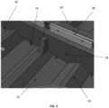
- Fig. 3 shows a detailed view of a flap valve.
- the left figure shows an exploded view of the flap valve.
- the flap valve comprises a clamping plate 24 with an integrated valve-flap stop.
- the clamping plate is preferably comprising a stiff material to hold the valve-flap properly at its desired attachment area at the liner segment side wall 14.
- the flap valve further comprises a valve-flap with reinforcement 26 at a feedthrough area.
- the flap valve with reinforcement 26 is made of aramid fiber with fluorosilicone plies with dissipative properties. Aramids have a very high melting point of more than 500 °C, which is advantageous in case of fire or similar undesired temperature peaks near the fuel tank structure.
- the flap valve further comprises a valve backplate 28.
- the valve back plate 28 comprises the same material as the clamping plate and is adapted to be connected to the clamping plate 24.
- the right figure shows a detailed side view of the flap valve in a mounted arrangement.
- the clamping plate 24 is in contact with the valve-flap with reinforcement 26.
- the valve-flap with reinforcement 26 seals the cut out 30 and therefore provides an unidirectional fluid connection from the bottom side of the liner segment 10 to the upper side of the liner segment 10, such that the unidirectional fluid connection is blocked in the opposite direction.
- Fig. 4 shows another detailed view of a flap valve in different states.
- the valve-flap with reinforcement 26 is open and enables a fluid flow from underneath the liner segment 10 to above the liner segment 10.
- the maximum opening position of the valve-flap with reinforcement 26 is restricted by the design of the clamping plate 24.
- valve-flap with reinforcement 26 is closed and prevents a fluid flow from underneath the liner segment 10 to above the liner segment 10. Therefore, the valve-flap provides an unidirectional fluid connection from the bottom side of the liner segment 10 to the upper side of the liner segment 10, such that the unidirectional fluid connection is blocked in the opposite direction.
- FIG. 1 In the figure on the right another view of the flap valve in the closed position is shown.
- Fig. 5 shows a system 50 for a tank structure, comprising a liner segment 10 and a multitude of frame bays 34.
- the liner segments 10, 10' are arranged in the frame bays 34.
- the system further comprises a multitude of liner segments 10' which is adapted to float on fuel in the tank structure.
- Each liner segment 10' is adapted to float on fuel in a corresponding one of the multitude of frame bays 34.
- each liner segment 10' comprises a liner segment base body 12' and at least one liner segment sidewall 14'.
- the liner segment sidewall 14' extends from the liner segment base body 12' and comprises a connection area and a multitude of connection profiles 38.
- the multitude of connection profiles 38 is adapted to connect the multitude of liner segments 10' and the liner segment 10.
- the system further comprises a fuel pump 36, wherein in the fuel pump 36 is adapted to pump fuel out of the tank structure at fuel pump picking points, such that a remaining portion of fuel within the fuel tank structure is reduced by securing the fuel flow from underneath a liner of the multitude of liner segments of an adjacent frame bay to the liner segment that is needed to extend safe fuel pump operation in the fuel tank structure.
- Fig. 6 shows an airplane 100 with a liner segment 10.
- the liner segment 10 comprises at least one valve 22, arranged in a cut 30 out of the liner segment 10.
- the at least one valve is adapted to provide an unidirectional fluid connection from the bottom side of the liner segment 10 to the upper side of the liner segment, such that the unidirectional fluid connection is blocked in the opposite direction.
- a remaining portion of fuel within the fuel tank structure is reduced by securing the fuel flow from underneath a liner segment 10 of an adjacent frame bay to the liner segment 10 that is needed to extend safe fuel pump operation in the fuel tank structure.
- a valve is a device that regulates the flow of a fluid, such that an unidirectional flow is provided, to increase the reachable fuel for the fuel pumps.
Landscapes
- Engineering & Computer Science (AREA)
- Aviation & Aerospace Engineering (AREA)
- Cooling, Air Intake And Gas Exhaust, And Fuel Tank Arrangements In Propulsion Units (AREA)
Abstract
Description
- The present invention relates to a liner segment for a frame bay of a fuel tank structure and a system for a tank structure, comprising such a liner segment.
- In aircrafts, a liner in each framebay of the fuselage can be used as an additional protection of a tank structure for the fuel needed to operate the aircraft. In the undesired case, for example caused by malfunction of the undercarriage during takeoff and landing, that a hole in the fuselage structure leads to a fuel leakage, the liner is an additional safety barrier and covers the hole and hereby decreases the leakage rate.
- To prevent corrosion caused by a liner next to the fuselage, in addition to the volume above the liner, there is an additional volume of fuel underneath the liner. This volume is feeding slowly in in the space underneath the liner by means of drainage holes. The diameter of the drainage holes within the framebay of fuel pump picking points are not large enough to make the volume underneath the liner consumable for the fuel pumps in time, because the pumps have to be shut down to protect them from the possibility to run dry. This leads to the situation of remaining fuel portion per each framebay of up to 20 liters of fuel.
- Thus, the current design leads to the situation that no overflow from one framebay to the adjacent one is possible, and therefore a relevant portion of fuel remains unusable and unreachable for fuel pumps within the tank.
- This either leads to a problem of weight due to the remaining fuel or even of fulfilling authorities safety requirements. The total weight of the unused fuel that is unreachable for the fuel pumps at the picking points can add up to more than 350 liters, which leads to need to improve the possibility to reach the remaining fuel for the fuel pumps to address the above-mentioned problems.
- It is an object to increase the usable tank volume and save weight due to reduction of remaining fuel portion for fulfillment of authority and customer requirements.
- This object is achieved by means of the subjects of the independent claims. Illustrative embodiments will be found in the dependent claims and the following description.
- According to one aspect, a liner segment for a frame bay of a fuel tank structure is provided. The liner segment comprises a liner segment base body, wherein the liner segment base body is adapted to float on fuel on the bottom of the fuel tank structure. In other words, the liner segment base body is a planar structure that is adapted to be arranged in a floating manner on the fuel tank structure to protect the fuselage of an aircraft, more specifically an additional protection of a tank structure against leakage in case of undesired holes in the fuselage.
- The liner segment further comprises at least one liner segment side wall, wherein the at least one liner segment side wall extends from the liner segment base body. Preferably the liner segment sidewall extends rectangular from the liner segment base body. More preferably the liner segment base body comprises a liner segment sidewall extending in a rectangular manner from each side of the liner segment base body. Preferably the height of the liner segment sidewall corresponds with the height of a frame in the fuselage of an aircraft.
- The liner segment further comprises a multitude of drainage holes, wherein the multitude of drainage holes is arranged in the liner segment base body. The multitude of drainage holes is adapted to provide a bidirectional fluid connection from an upper side of the liner segment to a bottom side of the liner segment facing the fuel tank structure. Preferably the multitude of drain holes is arranged near at least one liner segment side wall. Preferably a liner segment comprises more than 1, more preferably more than 15, most preferably more than 30 drainage holes, preferably arranged in an equidistant manner. In other words, the drainage holes enable the fuel from above the liner segment to flow in the space beneath the liner segment and vice versa, enabling the liner segment to float on the fuel beneath the liner segment.
- Further, the liner segment comprises at least one valve, arranged in a cut out of the liner segment. The at least one valve is adapted to provide an unidirectional fluid connection from the bottom side of the liner segment to the upper side of the liner segment, such that the unidirectional fluid connection is blocked in the opposite direction. In other words, the valve enables fuel from beneath the liner segment coming via the multitude of drainage holes to flow back above the liner segment. Concurrent, the valve is adapted to block fuel from above the liner segment to flow beneath the liner segment.
- Hence, a remaining portion of fuel within the fuel tank structure is reduced by securing the fuel flow from underneath a liner segment that is needed to extend safe fuel pump operation in the fuel tank structure. In other words, a valve is a device that regulates the flow of a fluid, such that an unidirectional flow is provided, and thereby increases the reachable fuel for the fuel pumps.
- Hence, the liner segment describes a concept to reduce the portion of remaining and therefore unusable fuel within a structural tank in combination with a liner material. Due to the fact that the diameters of the existing multitude of drainage holes are too small to ensure a proper overflow rate from adjacent frame bays or even just from underneath the liner, this remaining fuel portion is now consumable for the fuel pumps in the relevant frame bay via the valve.
- Therefore, it is proposed to install into the liner segment of the relevant frame bay with fuel pump picking point a dedicated number of valves which ensures a free flow of fuel from underneath the liner segment to above the liner segment and therefore increasing the overflow rate of fuel and making it consumable for the fuel pumps. A minimum fuel flow rate has to be ensured to protect the fuel pumps against running dry. The flow of fuel in the opposite direction is be blocked by the valve.
- According to one embodiment, the at least one valve is a flap valve. A flap valve permits fluid to flow in one direction while preventing backflow. A spring-loaded or weighted flap affixed to the opening of the cutout accomplishes this function. Flap valves are used to direct flow in the desired direction. They can be opened manually or remotely, and they can be opened by the force of the flow. The flap valve will open when direct pressure is applied to it, and it will close when that pressure is alleviated.
- In other words, it is proposed to introduce the flap valve in the frame bay of fuel pump picking points to reduce the unused fuel portions and to save weight to this remaining fuel.
- The total effective diameter of the flap valve is as big as needed to secure the fuel flow from underneath the liner of adj acent frame-bays in the tank that is needed to extend safe fuel pump operation.
- The flap valve is directly installed to the flexible liner material preferably without additional fixation to a sub-structure of the liner segment.
- The flap of the valve itself is preferably flexible with reinforcements to ensure proper operation and it is preferably clamped in between two plates.
- In case of structural failure of the tank itself, the flap valves will close caused by pressure degradation underneath the liner. This will ensure the proper function of the liner segment with its calculated leakage rate only caused by the diameters of the multitude of drainage holes.
- According to another embodiment, the at least one flap valve comprises a clamping plate with an integrated valve-flap stop, a valve-flap with reinforcement at a feedthrough area and a valve backplate.
- In an optional embodiment the valve further comprises a filter.
- According to another embodiment, the valve-flap comprises a flexible material.
- Another possible embodiment of a valve is a diaphragm valve. A diaphragm valve consists of a valve body with two or more ports, an elastomeric diaphragm, and a seat upon which the diaphragm closes the valve. The valve body may comprise plastic, metal, or other materials or material combinations.
- Another possible embodiment of a valve includes a flexible element like a spring, a rubber band or the like. The spring rate of the flexible element is adjusted in accordance with the desired flow rate of the fuel.
- According to another embodiment, the at least one valve is arranged in a cut out in the liner base body. The arrangement of the flap valves in the liner segment base body is advantageous for the flow of the remaining fuel since the liner segment base body is near the lowest point of the fuel tank structure. An arrangement of the flap valves in the liner segment base body is therefore advantageous to reduce the unreachable fuel to a desired minimum.
- According to another embodiment, the at least one valve is arranged in a cut out in the at least one liner segment side wall. It is also possible to combine the arrangement of the valves in the liner segment base body with the arrangement of valves in the liner segment side walls. Preferably the arrangement of the valves is in all liner segment side walls extending preferably in a rectangular manner from the liner segment base body.
- According to another embodiment, the liner segment comprises aramid fiber with fluorosilicone plies with dissipative properties. Aramid is short for aromatic polyamide, are a class of heat-resistant and strong synthetic fibers. The chain molecules in the fibers are highly oriented along the fiber axis. As a result, a higher proportion of the chemical bond contributes more to fiber strength than in many other synthetic fibers. Aramids have a very high melting point of more than 500 °C, which is advantageous in case of fire or similar undesired temperature peaks near the fuel tank structure.
- According to another embodiment, the at least one valve comprises a diameter of at least 10 mm and at most 75 mm. Preferably the valve comprises a diameter of 25,4 mm. In other embodiments the valve comprises a diameter with less than 10 mm or more the 75 mm.
- According to another embodiment, wherein each one of the multitude of the drainage holes comprises a diameter of at most 2 mm, preferably at most 8 mm. Preferably the drainage hole comprises a diameter of 6 mm. In other embodiments the valve comprises a diameter with less than 2 mm or more the 8 mm.
- According to another embodiment, the liner segment further comprises a multitude of longitudinal elevations, wherein in the multitude of longitudinal elevations is adapted to incorporate longitudinal stringers of the fuselage structure. In other words, an elevation is a channel-shaped elevation to cover a stringer and furthermore stiffens thin-walled components against deformation or vibration. The sidewalls of an elevation are also possible locations for arranging at least one valve adapted to provide an unidirectional fluid connection from the bottom side of the liner segment to the upper side of the liner segment, such that the unidirectional fluid connection is blocked in the opposite direction.
- According to another embodiment, the liner segment comprises at least four valves. Preferably the four valves are arranged in sets of two valves on opposite liner segment side walls. In other embodiments more than four valves are present in the liner segment.
- According to another embodiment, the frame bay is adapted to be connectable to a fuel pump at fuel pump picking points. The fuel system allows to pump, manage, and deliver the fuel to the propulsion system and auxiliary power unit.
- According to another aspect, a system for a tank structure comprising a liner segment with a valve for a frame bay of a fuel tank structure is provided. The liner segment comprises a liner segment base body, wherein the liner segment base body is adapted to float on fuel in the fuel tank structure, and at least one liner segment side wall, wherein the at least one liner segment side wall extends from the liner segment base body. The liner segment further comprises a multitude of drainage holes, wherein the multitude of drainage holes is arranged in the liner segment base body, and wherein the multitude of drainage holes is adapted to provide a bidirectional fluid connection from an upper side of the liner segment to a bottom side of the liner segment facing the fuel tank structure.
- Further, the liner segment comprises at least one valve, arranged in a cut out of the liner segment, wherein the at least one valve is adapted to provide an unidirectional fluid connection from the bottom side of the liner segment to the upper side of the liner segment, such that the unidirectional fluid connection is blocked in the opposite direction. Hence, a remaining portion of fuel within the fuel tank structure is reduced by securing the fuel flow from underneath a liner segment of an adjacent frame bay to the liner segment that is needed to extend safe fuel pump operation in the fuel tank structure.
- The system further comprises a multitude of frame bays and a multitude of liner segments which is adapted to float on fuel in the tank structure. Each liner segment is adapted to float on fuel in one of the associated multitude of frame bays, wherein each liner segment comprises a liner segment base body and at least one liner segment sidewall. The liner segment sidewall extends from the liner segment base body and comprises a connection area. Further, the system comprises a multitude of connection profiles. The multitude of connection profiles is adapted to connect the multitude of liner segments and the liner segment with the valve in the connection area.
- The system further comprises a fuel pump, wherein in the fuel pump is adapted to pump fuel out of the tank structure at fuel pump picking points, such that a remaining portion of fuel within the fuel tank structure is reduced by securing the fuel flow from underneath a liner of the multitude of liner segments of an adjacent frame bay to the liner segment that is needed to extend safe fuel pump operation in the fuel tank structure.
- According to another embodiment, wherein the system is arranged in an aircraft, wherein the aircraft is selected of a group consisting of airplane, helicopter or drone.
- According to another aspect, an airplane comprises a liner segment.
-
- Fig. 1
- shows a liner segment; and
- Fig. 2
- shows a detailed view of a liner segment; and
- Fig. 3
- shows two detailed views of a flap valve; and
- Fig. 4
- shows another detailed view of a flap valve in different states; and
- Fig. 5
- shows a system for a tank structure comprising a liner segment; and
- Fig. 6
- shows an airplane with a liner segment for a tank structure.
- The illustrations in the figures are schematic and not to scale. If the same reference signs are used in different figures in the following description of the figures, they designate identical or similar elements. However, identical or similar elements can also be designated by different reference symbols.
-
Fig. 1 shows aliner segment 10 for a frame bay 34 (not shown) of a fuel tank structure, comprising a linersegment base body 12, wherein the linersegment base body 12 is adapted to float on fuel in the fuel tank structure. The liner segment further comprises a linersegment side wall 14, wherein the liner segment side wall extends from the linersegment base body 12. The liner segment further comprises a multitude of drainage holes 16 (not shown), wherein the multitude of drainage holes 16 is arranged in the linersegment base body 12. - The multitude of drainage holes 16 is adapted to provide a bidirectional fluid connection from an
upper side 18 of theliner segment 10 to abottom side 20 of theliner segment 10 facing the fuel tank structure. Theliner segment 10 further comprises at least one valve 22 (not shown), arranged in a cut out 30 of theliner segment 10, wherein the at least onevalve 22 is adapted to provide an unidirectional fluid connection from thebottom side 20 of theliner segment 10 to theupper side 18 of theliner segment 10, such that the unidirectional fluid connection is blocked in the opposite direction. - Hence, a remaining portion of fuel within the fuel tank structure is reduced by securing the fuel flow from underneath the liner segment (not shown) of an adjacent frame bay to the
liner segment 10 that is needed to extend safe fuel pump operation in the fuel tank structure. - The
liner segment 10 according to the shown embodiment comprises fourcutouts 30 arranged on opposite sides of the linersegment side walls 14. -
Fig. 2 shows a detailed view of a section ofliner segment 10. Theliner segment 10 comprises a multitude of drainage holes 16, wherein the multitude of drainage holes 16 is arranged in the linersegment base body 12. - The multitude of drainage holes 16 is adapted to provide a bidirectional fluid connection from an
upper side 18 of theliner segment 10 to abottom side 20 of theliner segment 10 facing the fuel tank structure and vice versa. Theliner segment sidewall 14 extends from the linersegment base body 12 and comprises a connection area. Theliner segment 10 and the adjacent liner segment comprises a multitude of connection profiles 38, wherein the multitude of connection profiles 38 is adapted to connect the multitude ofliner segment 10 and the adjacent liner segment 10'. The drainage holes ensure only a very limited exchange of fuel from underneath theliner segment 10. -
Fig. 3 shows a detailed view of a flap valve. The left figure shows an exploded view of the flap valve. The flap valve comprises a clampingplate 24 with an integrated valve-flap stop. The clamping plate is preferably comprising a stiff material to hold the valve-flap properly at its desired attachment area at the linersegment side wall 14. The flap valve further comprises a valve-flap withreinforcement 26 at a feedthrough area. The flap valve withreinforcement 26 is made of aramid fiber with fluorosilicone plies with dissipative properties. Aramids have a very high melting point of more than 500 °C, which is advantageous in case of fire or similar undesired temperature peaks near the fuel tank structure. The flap valve further comprises avalve backplate 28. The valve backplate 28 comprises the same material as the clamping plate and is adapted to be connected to the clampingplate 24. - The right figure shows a detailed side view of the flap valve in a mounted arrangement. The clamping
plate 24 is in contact with the valve-flap withreinforcement 26. The valve-flap withreinforcement 26 seals the cut out 30 and therefore provides an unidirectional fluid connection from the bottom side of theliner segment 10 to the upper side of theliner segment 10, such that the unidirectional fluid connection is blocked in the opposite direction. -
Fig. 4 shows another detailed view of a flap valve in different states. In the figure on the left, the valve-flap withreinforcement 26 is open and enables a fluid flow from underneath theliner segment 10 to above theliner segment 10. The maximum opening position of the valve-flap withreinforcement 26 is restricted by the design of the clampingplate 24. - In the adjacent figure the valve-flap with
reinforcement 26 is closed and prevents a fluid flow from underneath theliner segment 10 to above theliner segment 10. Therefore, the valve-flap provides an unidirectional fluid connection from the bottom side of theliner segment 10 to the upper side of theliner segment 10, such that the unidirectional fluid connection is blocked in the opposite direction. In the figure on the right another view of the flap valve in the closed position is shown. -
Fig. 5 shows asystem 50 for a tank structure, comprising aliner segment 10 and a multitude of frame bays 34. Theliner segments 10, 10' are arranged in the frame bays 34. The system further comprises a multitude of liner segments 10' which is adapted to float on fuel in the tank structure. Each liner segment 10' is adapted to float on fuel in a corresponding one of the multitude of frame bays 34. - Further, each liner segment 10' comprises a liner segment base body 12' and at least one liner segment sidewall 14'. The liner segment sidewall 14' extends from the liner segment base body 12' and comprises a connection area and a multitude of connection profiles 38. The multitude of connection profiles 38 is adapted to connect the multitude of liner segments 10' and the
liner segment 10. - The system further comprises a
fuel pump 36, wherein in thefuel pump 36 is adapted to pump fuel out of the tank structure at fuel pump picking points, such that a remaining portion of fuel within the fuel tank structure is reduced by securing the fuel flow from underneath a liner of the multitude of liner segments of an adjacent frame bay to the liner segment that is needed to extend safe fuel pump operation in the fuel tank structure.Fig. 6 shows anairplane 100 with aliner segment 10. Further, theliner segment 10 comprises at least onevalve 22, arranged in acut 30 out of theliner segment 10. The at least one valve is adapted to provide an unidirectional fluid connection from the bottom side of theliner segment 10 to the upper side of the liner segment, such that the unidirectional fluid connection is blocked in the opposite direction. - Hence, a remaining portion of fuel within the fuel tank structure is reduced by securing the fuel flow from underneath a
liner segment 10 of an adjacent frame bay to theliner segment 10 that is needed to extend safe fuel pump operation in the fuel tank structure. In other words, a valve is a device that regulates the flow of a fluid, such that an unidirectional flow is provided, to increase the reachable fuel for the fuel pumps. -
- 10
- Liner segment
- 12
- liner segment base body
- 14
- liner segment side wall
- 16
- drainage holes
- 18
- upper side of the liner segment
- 20
- bottom side of the liner segment
- 22
- valve
- 24
- clamping plate
- 26
- valve flap with reinforcement
- 28
- valve backplate
- 30
- cut out
- 32
- longitudinal beads
- 34
- frame bay
- 36
- fuel pump
- 38
- connection profile
- 50
- System
- 100
- Airplane
Claims (15)
- A liner segment (10) for a frame bay (34) of a fuel tank structure, comprising:a liner segment base body (12), wherein the liner segment base body (12) is adapted to float on fuel in the fuel tank structure,at least one liner segment side wall (14), wherein the at least one liner segment side wall extends from the liner segment base body (12),a multitude of drainage holes (16), wherein the multitude of drainage holes (16) is arranged in the liner segment base body (12), and wherein the multitude of drainage holes (16) is adapted to provide a bidirectional fluid connection from an upper side (18) of the liner segment (10) to a bottom side (20) of the liner segment (10) facing the fuel tank structure,at least one valve (22), arranged in a cut out (30) of the liner segment (10),wherein the at least one valve (22) is adapted to provide an unidirectional fluid connection from the bottom side (20) of the liner segment (10) to the upper side (18) of the liner segment (10), such that the unidirectional fluid connection is blocked in the opposite direction,such that a remaining portion of fuel within the fuel tank structure is reduced by securing the fuel flow from underneath a liner segment of an adjacent frame bay to the liner segment (10) that is needed to extend safe fuel pump operation in the fuel tank structure.
- Liner segment (10) according to claim 1,
wherein the at least one valve (22) is a flap valve. - Liner segment (10) according to claim 2,
wherein the at least one flap valve comprises:a clamping plate (24) with an integrated valve-flap stop,a valve-flap with reinforcement (26) at a feedthrough area,a valve backplate (28). - Liner segment (10) according to claim 3,
wherein the flap valve comprises a flexible material. - Liner segment (10) according to one of the preceding claims,
wherein the at least one valve (22) is arranged in a cut out (30) in the liner segment base body (12). - Liner segment (10) according to one of the preceding claims,
wherein the at least one valve (22) is arranged in a cut out (30) in the at least one liner segment side wall (14). - Liner segment (10) according to one of the preceding claims,
wherein the liner segment (10) comprises aramid fiber with fluorosilicone plies with dissipative properties. - Liner segment (10) according to one of the preceding claims,
wherein the at least one valve (22) comprises a diameter of at least 10 mm and at most 75 mm. - Liner segment (10) according to one of the preceding claims,
wherein each one of the multitude of the drainage holes (16) comprises a diameter of at most 2 mm, preferably at most 8 mm. - Liner segment (10) according to one of the preceding claims,further comprising a multitude of longitudinal elevations (32),wherein in the multitude of longitudinal elevations (32) is adapted to incorporate longitudinal stringers of the fuselage structure.
- Liner segment (10) according to one of the preceding claims,
wherein the liner segment (10) comprises at least four valves (22). - Liner segment (10) according to one of the preceding claims,
wherein the frame bay (34) is adapted to be connectable to a fuel pump (36) at fuel pump picking points. - A system (50) for a tank structure, comprising a liner segment (10) according to claim 1 to 12,
wherein the system further comprises:a multitude of frame bays (34),a multitude of liner segments (10') which is adapted to float on fuel in the tank structure, wherein each liner segment (10') is adapted to float on fuel in one of the multitude of frame bays (34),wherein each liner segment (10') comprises a liner segment base body (12') and at least one liner segment sidewall (14'),wherein the liner segment sidewall (14') extends from the liner segment base body (12') and comprises a connection area,a multitude of connection profiles (38),wherein the multitude of connection profiles (38) is adapted to connect the multitude of liner segments (10') and the liner segment (10) according to claim 1 to 12,a fuel pump (36),wherein in the fuel pump (36) is adapted to pump fuel out of the tank structure at fuel pump picking points,such that a remaining portion of fuel within the fuel tank structure is reduced by securing the fuel flow from underneath a liner of the multitude of liner segments of an adjacent frame bay to the liner segment that is needed to extend safe fuel pump operation in the fuel tank structure. - System (50) according to claim 13,
wherein the system is arranged in an aircraft, wherein the aircraft is selected of a group consisting of: airplane, helicopter or drone. - An airplane (100) comprising a liner segment (10) according to claim 1 to 12.
Priority Applications (3)
| Application Number | Priority Date | Filing Date | Title |
|---|---|---|---|
| EP23169633.7A EP4455018B1 (en) | 2023-04-24 | 2023-04-24 | Liner segment for a frame bay of a fuel tank structure and system for a tank structure, comprising such a liner segment |
| US18/641,967 US12565329B2 (en) | 2023-04-24 | 2024-04-22 | Liner segment for a frame bay of a fuel tank structure and system for a tank structure, comprising such a liner segment |
| CN202410490302.5A CN118833403A (en) | 2023-04-24 | 2024-04-23 | Liner segment for a compartment of a fuel tank structure, and system for a tank structure comprising such a liner segment |
Applications Claiming Priority (1)
| Application Number | Priority Date | Filing Date | Title |
|---|---|---|---|
| EP23169633.7A EP4455018B1 (en) | 2023-04-24 | 2023-04-24 | Liner segment for a frame bay of a fuel tank structure and system for a tank structure, comprising such a liner segment |
Publications (2)
| Publication Number | Publication Date |
|---|---|
| EP4455018A1 true EP4455018A1 (en) | 2024-10-30 |
| EP4455018B1 EP4455018B1 (en) | 2026-02-11 |
Family
ID=86226447
Family Applications (1)
| Application Number | Title | Priority Date | Filing Date |
|---|---|---|---|
| EP23169633.7A Active EP4455018B1 (en) | 2023-04-24 | 2023-04-24 | Liner segment for a frame bay of a fuel tank structure and system for a tank structure, comprising such a liner segment |
Country Status (3)
| Country | Link |
|---|---|
| US (1) | US12565329B2 (en) |
| EP (1) | EP4455018B1 (en) |
| CN (1) | CN118833403A (en) |
Citations (2)
| Publication number | Priority date | Publication date | Assignee | Title |
|---|---|---|---|---|
| US5983945A (en) * | 1993-10-22 | 1999-11-16 | The United States Of America As Represented By The Secretary Of Transportation | Wing tank liner |
| US6408874B1 (en) * | 1997-02-20 | 2002-06-25 | Mannesmann Vdo Ag | Device for reducing splash noises in a fuel tank |
Family Cites Families (4)
| Publication number | Priority date | Publication date | Assignee | Title |
|---|---|---|---|---|
| SE530889C2 (en) * | 2007-02-27 | 2008-10-07 | Scania Cv Abp | Fuel tank arrangement for a vehicle |
| GB0720406D0 (en) * | 2007-10-19 | 2007-12-05 | Airbus Uk Ltd | Tank for containing a fluid within a chamber |
| FR2933067B1 (en) * | 2008-06-26 | 2010-10-08 | Airbus France | REINFORCED AIRCRAFT FUSELAGE PANEL AND METHOD FOR MANUFACTURING THE SAME |
| CN212355155U (en) * | 2020-04-20 | 2021-01-15 | 东北林业大学 | A flexible wave-suppressing floating plate for vehicle oil storage tank |
-
2023
- 2023-04-24 EP EP23169633.7A patent/EP4455018B1/en active Active
-
2024
- 2024-04-22 US US18/641,967 patent/US12565329B2/en active Active
- 2024-04-23 CN CN202410490302.5A patent/CN118833403A/en active Pending
Patent Citations (2)
| Publication number | Priority date | Publication date | Assignee | Title |
|---|---|---|---|---|
| US5983945A (en) * | 1993-10-22 | 1999-11-16 | The United States Of America As Represented By The Secretary Of Transportation | Wing tank liner |
| US6408874B1 (en) * | 1997-02-20 | 2002-06-25 | Mannesmann Vdo Ag | Device for reducing splash noises in a fuel tank |
Also Published As
| Publication number | Publication date |
|---|---|
| US20240351700A1 (en) | 2024-10-24 |
| EP4455018B1 (en) | 2026-02-11 |
| CN118833403A (en) | 2024-10-25 |
| US12565329B2 (en) | 2026-03-03 |
Similar Documents
| Publication | Publication Date | Title |
|---|---|---|
| US7857260B2 (en) | Fuel jettison system | |
| US6736354B2 (en) | Airplane fuel supply system and airplane wing pipeline assembly method | |
| US7337795B2 (en) | Fuel balancing system | |
| EP3173339B1 (en) | Aircraft fuel system | |
| US7568660B2 (en) | Auxiliary fuel tank systems for aircraft and methods for their manufacture and use | |
| US7357355B2 (en) | Auxiliary fuel tank systems for aircraft and methods for their manufacture and use | |
| US9517842B2 (en) | Filters for aircraft engine inlets | |
| CA2510218C (en) | Hingeless flapper valve for flow control | |
| WO2007008185A2 (en) | Method and arrangement for aircraft fuel dispersion | |
| EP2592316A1 (en) | Clack valve assembly | |
| US12565329B2 (en) | Liner segment for a frame bay of a fuel tank structure and system for a tank structure, comprising such a liner segment | |
| EP2021235A1 (en) | Line system arrangement in an aircraft or spacecraft having a fuselage | |
| WO2008048267A1 (en) | Fuel balancing system | |
| US10421555B2 (en) | Aircraft fuel system | |
| US5983945A (en) | Wing tank liner | |
| EP1832512A2 (en) | Compact, lightweight cabin pressure control system butterfly outflow valve with redundancy features | |
| JP4021211B2 (en) | Airplane fuel supply system | |
| EP3628582B1 (en) | System and method for enhanced fuel cell protection from adjacent damaged components | |
| EP3575220B1 (en) | An aircraft fuel tank system | |
| US11745850B2 (en) | Aircraft wing box | |
| US10017049B2 (en) | Vent valve, tank having vent valve, and method | |
| EP2293982A1 (en) | Fuel jettison system | |
| US20250060047A1 (en) | Fluid discharge system | |
| CN119734841A (en) | A fuel tank connected by a lightweight one-way valve | |
| US20240246691A1 (en) | Aircraft comprising a fuel tank |
Legal Events
| Date | Code | Title | Description |
|---|---|---|---|
| PUAI | Public reference made under article 153(3) epc to a published international application that has entered the european phase |
Free format text: ORIGINAL CODE: 0009012 |
|
| STAA | Information on the status of an ep patent application or granted ep patent |
Free format text: STATUS: THE APPLICATION HAS BEEN PUBLISHED |
|
| AK | Designated contracting states |
Kind code of ref document: A1 Designated state(s): AL AT BE BG CH CY CZ DE DK EE ES FI FR GB GR HR HU IE IS IT LI LT LU LV MC ME MK MT NL NO PL PT RO RS SE SI SK SM TR |
|
| STAA | Information on the status of an ep patent application or granted ep patent |
Free format text: STATUS: REQUEST FOR EXAMINATION WAS MADE |
|
| 17P | Request for examination filed |
Effective date: 20250404 |
|
| GRAP | Despatch of communication of intention to grant a patent |
Free format text: ORIGINAL CODE: EPIDOSNIGR1 |
|
| STAA | Information on the status of an ep patent application or granted ep patent |
Free format text: STATUS: GRANT OF PATENT IS INTENDED |
|
| RIC1 | Information provided on ipc code assigned before grant |
Ipc: B64D 37/06 20060101AFI20250819BHEP |
|
| INTG | Intention to grant announced |
Effective date: 20250905 |
|
| GRAS | Grant fee paid |
Free format text: ORIGINAL CODE: EPIDOSNIGR3 |
|
| GRAA | (expected) grant |
Free format text: ORIGINAL CODE: 0009210 |
|
| STAA | Information on the status of an ep patent application or granted ep patent |
Free format text: STATUS: THE PATENT HAS BEEN GRANTED |
|
| AK | Designated contracting states |
Kind code of ref document: B1 Designated state(s): AL AT BE BG CH CY CZ DE DK EE ES FI FR GB GR HR HU IE IS IT LI LT LU LV MC ME MK MT NL NO PL PT RO RS SE SI SK SM TR |
|
| REG | Reference to a national code |
Ref country code: CH Ref legal event code: F10 Free format text: ST27 STATUS EVENT CODE: U-0-0-F10-F00 (AS PROVIDED BY THE NATIONAL OFFICE) Effective date: 20260211 Ref country code: GB Ref legal event code: FG4D |
|
| REG | Reference to a national code |
Ref country code: DE Ref legal event code: R096 Ref document number: 602023011758 Country of ref document: DE |
|
| REG | Reference to a national code |
Ref country code: IE Ref legal event code: FG4D |