EP4455007A1 - Crew rest system for an internal cabin of an aircraft - Google Patents

Crew rest system for an internal cabin of an aircraft Download PDF

Info

Publication number
EP4455007A1
EP4455007A1 EP24159794.7A EP24159794A EP4455007A1 EP 4455007 A1 EP4455007 A1 EP 4455007A1 EP 24159794 A EP24159794 A EP 24159794A EP 4455007 A1 EP4455007 A1 EP 4455007A1
Authority
EP
European Patent Office
Prior art keywords
overhead
crew rest
rest system
monument
bunk
Prior art date
Legal status (The legal status is an assumption and is not a legal conclusion. Google has not performed a legal analysis and makes no representation as to the accuracy of the status listed.)
Pending
Application number
EP24159794.7A
Other languages
German (de)
French (fr)
Inventor
Rohan Srinivas Sharma
Paul Addis
Sachel C. DAVIS-DELANO
Justin L. TABORA
Current Assignee (The listed assignees may be inaccurate. Google has not performed a legal analysis and makes no representation or warranty as to the accuracy of the list.)
Boeing Co
Original Assignee
Boeing Co
Priority date (The priority date is an assumption and is not a legal conclusion. Google has not performed a legal analysis and makes no representation as to the accuracy of the date listed.)
Filing date
Publication date
Application filed by Boeing Co filed Critical Boeing Co
Publication of EP4455007A1 publication Critical patent/EP4455007A1/en
Pending legal-status Critical Current

Links

Images

Classifications

    • BPERFORMING OPERATIONS; TRANSPORTING
    • B64AIRCRAFT; AVIATION; COSMONAUTICS
    • B64DEQUIPMENT FOR FITTING IN OR TO AIRCRAFT; FLIGHT SUITS; PARACHUTES; ARRANGEMENT OR MOUNTING OF POWER PLANTS OR PROPULSION TRANSMISSIONS IN AIRCRAFT
    • B64D11/00Passenger or crew accommodation; Flight-deck installations not otherwise provided for
    • B64D11/04Galleys
    • BPERFORMING OPERATIONS; TRANSPORTING
    • B64AIRCRAFT; AVIATION; COSMONAUTICS
    • B64DEQUIPMENT FOR FITTING IN OR TO AIRCRAFT; FLIGHT SUITS; PARACHUTES; ARRANGEMENT OR MOUNTING OF POWER PLANTS OR PROPULSION TRANSMISSIONS IN AIRCRAFT
    • B64D11/00Passenger or crew accommodation; Flight-deck installations not otherwise provided for
    • B64D11/0007Devices specially adapted for food or beverage distribution services
    • BPERFORMING OPERATIONS; TRANSPORTING
    • B64AIRCRAFT; AVIATION; COSMONAUTICS
    • B64DEQUIPMENT FOR FITTING IN OR TO AIRCRAFT; FLIGHT SUITS; PARACHUTES; ARRANGEMENT OR MOUNTING OF POWER PLANTS OR PROPULSION TRANSMISSIONS IN AIRCRAFT
    • B64D11/00Passenger or crew accommodation; Flight-deck installations not otherwise provided for
    • B64D2011/0069Rest berths, beds or the like
    • B64D2011/0076Rest berths, beds or the like for crew members, e.g. for sleeping during flight

Definitions

  • Examples of the present disclosure generally relate to a crew rest system for an internal cabin of a vehicle, such as a commercial aircraft.
  • Vehicles such as commercial aircraft are used to transport passengers between various locations.
  • a typical commercial aircraft includes an internal cabin having seats for passengers.
  • a crew rest area in the form of an overhead flight crew rest (OFCR) area is disposed within an internal cabin of certain aircraft.
  • OFCR overhead flight crew rest
  • One known OFCR area is 58 inches long, and another known OFCR area is 80 inches long.
  • a known 58 inch OFCR area houses only two galley carts in a forward facing compartment.
  • a known 80 inch version houses four galley carts, although within a substantially larger footprint.
  • the crew rest system includes a monument having a cart compartment configured to retain three or more galley carts.
  • An access area having an entrance is on a side of the monument.
  • the entrance leads into an internal passage having steps.
  • the monument is a forward monument and the cart compartment is a front compartment that faces forward.
  • the cart compartment is configured to retain four full-sized galley carts.
  • the vehicle is an aircraft.
  • the access area can be behind a portion of the cart compartment.
  • a storage area can be to a side of the access area.
  • the width of the monument is 53 inches, and a length of the monument is 61 inches.
  • the crew rest system also included an overhead bunk module including a bunk.
  • the access area leads to the overhead bunk module.
  • the overhead bunk module is configured to extend over portions of one or both of seats or overhead stowage bin assemblies within the internal cabin.
  • the cart compartment can be in front of and below the overhead bunk module.
  • a door moveable between an open position and a closed position allows for the entrance to be selectively opened and closed.
  • the crew rest system also includes a forward rest area having a seat.
  • the forward rest area is disposed over at least a portion of the cart compartment.
  • the access area leads to the forward rest area.
  • the crew rest system includes an overhead bunk module including a bunk, and a forward rest area including a seat.
  • the access area leads to the overhead bunk module and the forward rest area.
  • Examples of the present disclosure provide a crew rest system that provides a cart storage capability of a known 80 inch overhead flight crew rest (OFCR) area in a more compact footprint.
  • the crew rest system is 3 inches longer than a known 56 inch OFCR area, with a forward monument being able to house four galley carts in a forward-facing compartment.
  • Examples of the present disclosure provide a vehicle, such as an aircraft, including an internal cabin.
  • a crew rest system is within the internal cabin.
  • the crew rest system includes a forward monument including a front cart compartment and an entrance.
  • the front compartment faces forward (that is, toward a fore end of the aircraft in contrast to an aft end) and is configured to retain a plurality of galley carts, such as three or more galley carts.
  • the front compartment is configured to retain four galley carts.
  • the entrance is on a side of the forward monument.
  • the entrance leads into an internal passage having steps.
  • the crew rest system also includes an overhead bunk module coupled to the forward monument.
  • the overhead bunk module can extend over portions of seats and/or overhead stowage bin assemblies.
  • the forward monument also includes a forward rest area having a seat.
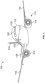
  • Figure 1 illustrates a perspective front view of an aircraft 100, according to an example of the present disclosure.
  • the aircraft 100 includes a propulsion system 112 that includes engines 114, for example.
  • the propulsion system 112 may include more engines 114 than shown.
  • the engines 114 are carried by wings 116 of the aircraft 100.
  • the engines 114 may be carried by a fuselage 118 and/or an empennage 120.
  • the empennage 120 may also support horizontal stabilizers 122 and a vertical stabilizer 124.
  • the fuselage 118 of the aircraft 100 defines an internal cabin 130, which includes a flight deck or cockpit, one or more work sections (for example, galleys, personnel carry-on baggage areas, and the like), one or more passenger sections (for example, first class, business class, and coach sections), one or more lavatories, and/or the like.
  • work sections for example, galleys, personnel carry-on baggage areas, and the like
  • passenger sections for example, first class, business class, and coach sections
  • lavatories for example, first class, business class, and coach sections
  • examples of the present disclosure may be used with various other vehicles, such as automobiles, buses, locomotives and train cars, watercraft, and the like.
  • Figure 2 illustrates a perspective interior view of an internal cabin 130 of an aircraft, according to an example of the present disclosure.
  • the internal cabin 130 includes outboard walls 132 and a ceiling 134. Windows 136 may be formed within the outboard walls 132.
  • a floor 138 supports rows of seats 140. As shown in Figure 2 , a row 142 may include three seats 140 on either side of an aisle 143. However, the row 142 may include more or less seats 140 than shown. Additionally, the internal cabin 130 may include more aisles than shown.
  • outboard means a position that is further away from a central longitudinal plane 150 of the internal cabin 130 as compared to another component.
  • inboard means a position that is closer to the central longitudinal plane 150 of the internal cabin 130 as compared to another component.
  • FIG 3 illustrates a schematic top plan view of a crew rest system 200 for an internal cabin of a vehicle (such as the aircraft 100 shown in Figure 1 ), according to an example of the present disclosure.
  • the crew rest system 200 includes a forward monument 202 including a front cart compartment 204 that faces forward. That is, the front cart compartment 204 faces toward a fore end of the vehicle.
  • the front cart compartment 204 is oriented to face toward a flight deck or cockpit of an aircraft.
  • the front cart compartment 204 has one or more cart passages that face forward.
  • the front cart compartment 204 is configured to retain four galley carts 206, such as full-sized galley carts.
  • the front cart compartment 204 includes one or more bays 208 that are configured to retain the galley carts.
  • Each bay 208 can include one or more walls that are configured that define an internal chamber into which a galley cart 206 is retained.
  • the front cart compartment 204 can include a single bay that retains the four galley carts 206.
  • the front cart compartment 204 can include a single central dividing wall that divides that front cart compartment 204 into two bays, each of which is configured to retain two galley carts 206.
  • the crew rest system 200 also includes an access area 210 behind a portion of the front cart compartment 204.
  • the access area 210 can be a vestibule having one or more steps that lead up to one or both of a forward rest area and/or an overhead bunk module.
  • the crew rest system 200 can also include a storage area 212 to a side of the access area 210, and behind a portion of the front cart compartment 204.
  • the storage area 212 can be configured to store additional component, such as half-sized galley carts 214, emergency equipment 216, and/or the like.
  • the crew rest system 200 provides a monument (such as the forward monument) having a width W within an internal cabin.
  • the width W is 53 inches.
  • a length L of the monument spanning from a front end 218 of the front cart compartment 204 to a rear end 220 of the access area 210 can be 61 inches. It has been found that the forward monument having the width W of 53 inches, and a length L of 61 inches allows for a desirable compact structure that is able to retain four full-sized galley carts, and provide a desirable resting area for crew, while at the same time having a footprint that does not obtrude into space for seats within an internal cabin of an aircraft.
  • the length L can be less than 61 inches (such as 55-60 inches) or greater than 61 inches (such as 62-63 inches).
  • a length L' of the access area 210 can be 22.5 inches.
  • the length L' can be less than 22.5 inches (such as 20-22 inches), or greater than 22.5 inches (such as 23-24 inches).
  • the width W can be less than 53 inches (such as 50-52 inches) or greater than 53 inches (such as 54-55 inches).
  • a width W' of the access area 210 can be 14.9 inches.
  • the width W' can be less than 14.9 inches (such as 13-14 inches), or greater than 14.9 inches (such as 15-16 inches).
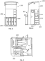
  • FIG 4 illustrates an isometric front, lateral view of the crew rest system 200, according to an example of the present disclosure.
  • Figure 5 illustrates a front view of the crew rest system 200 of Figure 4 .
  • Figure 6 illustrates a lateral view of the crew rest system 200 of Figure 4 .
  • Figure 7 illustrates a top view of the crew rest system 200 of Figure 4 .
  • the crew rest system 200 includes the forward monument 202 connected to an overhead bunk module 230, which can extend over portions of seats and/or overhead stowage bin assemblies within the internal cabin.
  • the overhead bunk module 230 can have at least a portion disposed over the front cart compartment 204.
  • the overhead bunk module 230 does not have a portion disposed over the front cart compartment 204.
  • the access area 210 includes steps that allow an individual to climb up into the overhead bunk module 230.
  • the front cart compartment 204 has one or more cart passages 232 that face forward. As shown, the front cart compartment 204 is configured to retain four galley carts 206, such as full-sized galley carts.
  • the forward monument 202 is in front of, and below, the overhead bunk module 230.
  • the forward monument 202 is closer to a fore end of the internal cabin than the overhead bunk module 230.
  • the overhead bunk module 230 is behind the forward monument 202.
  • the overhead bunk module 230 is closer to the aft end than the forward monument 202.
  • the forward monument 202 can be a rear monument that is behind the overhead bunk module 230.
  • the forward monument 202 includes the access area 210, which includes an entrance 234 located on a side 236 of the forward monument 202 (instead of the front).
  • the forward monument 202 also includes a forward rest area 250.
  • a door 238 is moveable between an open position and a closed position to selectively open and close the entrance 234.
  • the entrance 234 leads into an internal passage 240 having steps 242 that allow an individual to step into the forward rest area 250, which can include a seat 252.
  • the forward rest area 250 can be disposed above the front cart compartment 204, and in front of the overhead bunk module 230.
  • the internal passage 240 and the forward rest area 250 also lead into a bunk chamber of the overhead bunk module 230.
  • the crew rest system 200 does not include the overhead bunk module 230. Instead, the entrance 234 may lead to the forward rest area 250 above at least a portion of the front cart compartment 204, but not to an overhead bunk module 230.
  • the crew rest system 200 does not include the forward rest area 250.
  • the forward monument 202 may not include a forward rest area.
  • the entrance 234 may lead to the overhead bunk module 230, which can include one or more portions over the front cart compartment 204.
  • FIG 8 illustrates a top plan view of the crew rest system 200 within an internal cabin 300 of an aircraft 302, according to an example of the present disclosure.
  • the crew rest system 200 provides an optimized OFCR configuration.
  • the crew rest system 200 is able to house an additional two galley carts (for a total of four full-sized galley carts), and provide additional storage capability and additional countertop space, while only being 3 inches longer than a baseline (58 inches long) OFCR design.
  • the crew rest system 200 bolsters forward galley cart capacity, and allows for additional passenger seats within the internal cabin.
  • Figure 9 illustrates an isometric front, lateral view of the crew rest system 200, according to an example of the present disclosure.
  • the crew rest system 200 can be configured to be retrofit into existing internal cabins, such as via upper attachment fittings 400 that are configured to connect to structure in the ceiling.
  • Floor attachments 402 can be secured to lower portions of the crew rest system 200.
  • the floor attachments 402 are configured to secure to reciprocal structures on or within a floor of an internal cabin.
  • FIG 10 illustrates an aft view an overhead bunk module 230 from a forward rest area, according to an example of the present disclosure.
  • the access area 210 can include steps 242 that allow an individual to climb up into the overhead bunk module 230.
  • the overhead bunk module 230 defines a bunk chamber 231 having a bunk 233 (such as a padded support sheet, bed, cot, or the like).
  • examples of the present disclosure provide an improved crew rest system for an internal cabin of an aircraft. Further, examples of the present disclosure provide a compact crew rest system having increased cart storage capability.
  • a structure, limitation, or element that is "configured to” perform a task or operation is particularly structurally formed, constructed, or adapted in a manner corresponding to the task or operation.
  • an object that is merely capable of being modified to perform the task or operation is not “configured to” perform the task or operation as used herein.

Landscapes

  • Engineering & Computer Science (AREA)
  • Aviation & Aerospace Engineering (AREA)
  • Body Structure For Vehicles (AREA)

Abstract

A crew rest system for an internal cabin of a vehicle, such as a commercial aircraft, includes a monument having a cart compartment configured to retain three or more galley carts. An access area having an entrance is on a side of the monument. The entrance leads into an internal passage having steps.

Description

    CROSS-REFERENCE TO RELATED APPLICATIONS
  • This application is a non-provisional conversion of, and claims priority to, U.S. Provisional Patent Application No. 63/498,056, filed April 25, 2023 , which is incorporated by reference in its entirety.
  • FIELD OF THE DISCLOSURE
  • Examples of the present disclosure generally relate to a crew rest system for an internal cabin of a vehicle, such as a commercial aircraft.
  • BACKGROUND OF THE DISCLOSURE
  • Vehicles such as commercial aircraft are used to transport passengers between various locations. A typical commercial aircraft includes an internal cabin having seats for passengers.
  • During certain types of flights, such as long haul flights, crew members of an aircraft may need to rest. As such, certain aircraft include crew rest areas. For example, a crew rest area in the form of an overhead flight crew rest (OFCR) area is disposed within an internal cabin of certain aircraft. One known OFCR area is 58 inches long, and another known OFCR area is 80 inches long. A known 58 inch OFCR area houses only two galley carts in a forward facing compartment. In contrast, a known 80 inch version houses four galley carts, although within a substantially larger footprint.
  • While the cart storage capability of the 80 inch version may be desirable, the large footprint of such version necessarily reduces space for seats within the internal cabin.
  • SUMMARY OF THE DISCLOSURE
  • A need exists for an improved crew rest system for an internal cabin of an aircraft. Further, a need exists for a compact crew rest system for an internal cabin of an aircraft having increased cart storage capability.
  • With those needs in mind, certain examples of the present disclosure provide a crew rest system for an internal cabin of a vehicle. The crew rest system includes a monument having a cart compartment configured to retain three or more galley carts. An access area having an entrance is on a side of the monument. The entrance leads into an internal passage having steps.
  • In at least one example, the monument is a forward monument and the cart compartment is a front compartment that faces forward.
  • In at least one example, the cart compartment is configured to retain four full-sized galley carts.
  • In at least one example, the vehicle is an aircraft.
  • The access area can be behind a portion of the cart compartment. A storage area can be to a side of the access area.
  • In at least one example, the width of the monument is 53 inches, and a length of the monument is 61 inches.
  • In at least one example, the crew rest system also included an overhead bunk module including a bunk. The access area leads to the overhead bunk module. The overhead bunk module is configured to extend over portions of one or both of seats or overhead stowage bin assemblies within the internal cabin. The cart compartment can be in front of and below the overhead bunk module.
  • A door moveable between an open position and a closed position allows for the entrance to be selectively opened and closed.
  • In at least one example, the crew rest system also includes a forward rest area having a seat. The forward rest area is disposed over at least a portion of the cart compartment. The access area leads to the forward rest area.
  • In at least one example, the crew rest system includes an overhead bunk module including a bunk, and a forward rest area including a seat. The access area leads to the overhead bunk module and the forward rest area.
  • BRIEF DESCRIPTION OF THE DRAWINGS
    • Figure 1 illustrates a perspective front view of an aircraft, according to an example of the present disclosure.
    • Figure 2 illustrates a perspective interior view of an internal cabin of an aircraft, according to an example of the present disclosure.
    • Figure 3 illustrates a schematic top plan view of a crew rest system for an internal cabin of a vehicle, according to an example of the present disclosure.
    • Figure 4 illustrates an isometric front, lateral view of the crew rest system, according to an example of the present disclosure.
    • Figure 5 illustrates a front view of the crew rest system of Figure 4.
    • Figure 6 illustrates a lateral view of the crew rest system of Figure 4.
    • Figure 7 illustrates a top view of the crew rest system of Figure 4.
    • Figure 8 illustrates a top plan view of a crew rest system within an internal cabin of an aircraft, according to an example of the present disclosure.
    • Figure 9 illustrates an isometric front, lateral view of the crew rest system, according to an example of the present disclosure.
    • Figure 10 illustrates an aft view an overhead bunk module from a forward rest area, according to an example of the present disclosure.
    DETAILED DESCRIPTION OF THE DISCLOSURE
  • The foregoing summary, as well as the following detailed description of certain embodiments will be better understood when read in conjunction with the appended drawings. As used herein, an element or step recited in the singular and preceded by the word "a" or "an" should be understood as not necessarily excluding the plural of the elements or steps. Further, references to "one embodiment" are not intended to be interpreted as excluding the existence of additional embodiments that also incorporate the recited features. Moreover, unless explicitly stated to the contrary, embodiments "comprising" or "having" an element or a plurality of elements having a particular condition can include additional elements not having that condition.
  • Examples of the present disclosure provide a crew rest system that provides a cart storage capability of a known 80 inch overhead flight crew rest (OFCR) area in a more compact footprint. In at least one example, the crew rest system is 3 inches longer than a known 56 inch OFCR area, with a forward monument being able to house four galley carts in a forward-facing compartment.
  • Examples of the present disclosure provide a vehicle, such as an aircraft, including an internal cabin. A crew rest system is within the internal cabin. The crew rest system includes a forward monument including a front cart compartment and an entrance. In at least one example, the front compartment faces forward (that is, toward a fore end of the aircraft in contrast to an aft end) and is configured to retain a plurality of galley carts, such as three or more galley carts. For example, the front compartment is configured to retain four galley carts. The entrance is on a side of the forward monument. The entrance leads into an internal passage having steps. In at least one example, the crew rest system also includes an overhead bunk module coupled to the forward monument. The overhead bunk module can extend over portions of seats and/or overhead stowage bin assemblies. In at least one example, the forward monument also includes a forward rest area having a seat.
  • Figure 1 illustrates a perspective front view of an aircraft 100, according to an example of the present disclosure. The aircraft 100 includes a propulsion system 112 that includes engines 114, for example. Optionally, the propulsion system 112 may include more engines 114 than shown. The engines 114 are carried by wings 116 of the aircraft 100. In other examples, the engines 114 may be carried by a fuselage 118 and/or an empennage 120. The empennage 120 may also support horizontal stabilizers 122 and a vertical stabilizer 124.
  • The fuselage 118 of the aircraft 100 defines an internal cabin 130, which includes a flight deck or cockpit, one or more work sections (for example, galleys, personnel carry-on baggage areas, and the like), one or more passenger sections (for example, first class, business class, and coach sections), one or more lavatories, and/or the like.
  • Alternatively, instead of an aircraft, examples of the present disclosure may be used with various other vehicles, such as automobiles, buses, locomotives and train cars, watercraft, and the like.
  • Figure 2 illustrates a perspective interior view of an internal cabin 130 of an aircraft, according to an example of the present disclosure. The internal cabin 130 includes outboard walls 132 and a ceiling 134. Windows 136 may be formed within the outboard walls 132. A floor 138 supports rows of seats 140. As shown in Figure 2, a row 142 may include three seats 140 on either side of an aisle 143. However, the row 142 may include more or less seats 140 than shown. Additionally, the internal cabin 130 may include more aisles than shown.
  • As used herein, the term "outboard" means a position that is further away from a central longitudinal plane 150 of the internal cabin 130 as compared to another component. The term "inboard" means a position that is closer to the central longitudinal plane 150 of the internal cabin 130 as compared to another component.
  • Figure 3 illustrates a schematic top plan view of a crew rest system 200 for an internal cabin of a vehicle (such as the aircraft 100 shown in Figure 1), according to an example of the present disclosure. The crew rest system 200 includes a forward monument 202 including a front cart compartment 204 that faces forward. That is, the front cart compartment 204 faces toward a fore end of the vehicle. For example, the front cart compartment 204 is oriented to face toward a flight deck or cockpit of an aircraft. In at least one example, the front cart compartment 204 has one or more cart passages that face forward. In at least one example, the front cart compartment 204 is configured to retain four galley carts 206, such as full-sized galley carts. For example, the front cart compartment 204 includes one or more bays 208 that are configured to retain the galley carts. Each bay 208 can include one or more walls that are configured that define an internal chamber into which a galley cart 206 is retained. Optionally, the front cart compartment 204 can include a single bay that retains the four galley carts 206. As another example, the front cart compartment 204 can include a single central dividing wall that divides that front cart compartment 204 into two bays, each of which is configured to retain two galley carts 206.
  • The crew rest system 200 also includes an access area 210 behind a portion of the front cart compartment 204. The access area 210 can be a vestibule having one or more steps that lead up to one or both of a forward rest area and/or an overhead bunk module.
  • The crew rest system 200 can also include a storage area 212 to a side of the access area 210, and behind a portion of the front cart compartment 204. The storage area 212 can be configured to store additional component, such as half-sized galley carts 214, emergency equipment 216, and/or the like.
  • As shown, the crew rest system 200 provides a monument (such as the forward monument) having a width W within an internal cabin. In at least one example, the width W is 53 inches. A length L of the monument spanning from a front end 218 of the front cart compartment 204 to a rear end 220 of the access area 210 can be 61 inches. It has been found that the forward monument having the width W of 53 inches, and a length L of 61 inches allows for a desirable compact structure that is able to retain four full-sized galley carts, and provide a desirable resting area for crew, while at the same time having a footprint that does not obtrude into space for seats within an internal cabin of an aircraft.
  • Optionally, the length L can be less than 61 inches (such as 55-60 inches) or greater than 61 inches (such as 62-63 inches). A length L' of the access area 210 can be 22.5 inches. Optionally, the length L' can be less than 22.5 inches (such as 20-22 inches), or greater than 22.5 inches (such as 23-24 inches). Optionally, the width W can be less than 53 inches (such as 50-52 inches) or greater than 53 inches (such as 54-55 inches). A width W' of the access area 210 can be 14.9 inches. Optionally, the width W' can be less than 14.9 inches (such as 13-14 inches), or greater than 14.9 inches (such as 15-16 inches).
  • Figure 4 illustrates an isometric front, lateral view of the crew rest system 200, according to an example of the present disclosure. Figure 5 illustrates a front view of the crew rest system 200 of Figure 4. Figure 6 illustrates a lateral view of the crew rest system 200 of Figure 4. Figure 7 illustrates a top view of the crew rest system 200 of Figure 4. Referring to Figures 4-7, the crew rest system 200 includes the forward monument 202 connected to an overhead bunk module 230, which can extend over portions of seats and/or overhead stowage bin assemblies within the internal cabin. The overhead bunk module 230 can have at least a portion disposed over the front cart compartment 204. Optionally, the overhead bunk module 230 does not have a portion disposed over the front cart compartment 204. The access area 210 includes steps that allow an individual to climb up into the overhead bunk module 230.
  • As shown, the front cart compartment 204 has one or more cart passages 232 that face forward. As shown, the front cart compartment 204 is configured to retain four galley carts 206, such as full-sized galley carts.
  • In at least one example, the forward monument 202 is in front of, and below, the overhead bunk module 230. The forward monument 202 is closer to a fore end of the internal cabin than the overhead bunk module 230. In contrast, the overhead bunk module 230 is behind the forward monument 202. The overhead bunk module 230 is closer to the aft end than the forward monument 202. Alternatively, the forward monument 202 can be a rear monument that is behind the overhead bunk module 230.
  • In at least one example, the forward monument 202 includes the access area 210, which includes an entrance 234 located on a side 236 of the forward monument 202 (instead of the front). The forward monument 202 also includes a forward rest area 250. A door 238 is moveable between an open position and a closed position to selectively open and close the entrance 234. The entrance 234 leads into an internal passage 240 having steps 242 that allow an individual to step into the forward rest area 250, which can include a seat 252. The forward rest area 250 can be disposed above the front cart compartment 204, and in front of the overhead bunk module 230. The internal passage 240 and the forward rest area 250 also lead into a bunk chamber of the overhead bunk module 230.
  • In at least one example, the crew rest system 200 does not include the overhead bunk module 230. Instead, the entrance 234 may lead to the forward rest area 250 above at least a portion of the front cart compartment 204, but not to an overhead bunk module 230.
  • In at least one other example, the crew rest system 200 does not include the forward rest area 250. For example, the forward monument 202 may not include a forward rest area. Instead, the entrance 234 may lead to the overhead bunk module 230, which can include one or more portions over the front cart compartment 204.
  • Figure 8 illustrates a top plan view of the crew rest system 200 within an internal cabin 300 of an aircraft 302, according to an example of the present disclosure. Referring to Figures 3-8. the crew rest system 200 provides an optimized OFCR configuration. In at least one example, by reconfiguring and spatially optimizing components, the crew rest system 200 is able to house an additional two galley carts (for a total of four full-sized galley carts), and provide additional storage capability and additional countertop space, while only being 3 inches longer than a baseline (58 inches long) OFCR design. The crew rest system 200 bolsters forward galley cart capacity, and allows for additional passenger seats within the internal cabin.
  • Figure 9 illustrates an isometric front, lateral view of the crew rest system 200, according to an example of the present disclosure. The crew rest system 200 can be configured to be retrofit into existing internal cabins, such as via upper attachment fittings 400 that are configured to connect to structure in the ceiling. Floor attachments 402 can be secured to lower portions of the crew rest system 200. The floor attachments 402 are configured to secure to reciprocal structures on or within a floor of an internal cabin.
  • Figure 10 illustrates an aft view an overhead bunk module 230 from a forward rest area, according to an example of the present disclosure. The access area 210 can include steps 242 that allow an individual to climb up into the overhead bunk module 230. The overhead bunk module 230 defines a bunk chamber 231 having a bunk 233 (such as a padded support sheet, bed, cot, or the like).
  • Further, the disclosure comprises examples according to the following clauses:
    • Clause 1. A crew rest system for an internal cabin of a vehicle, the crew rest system comprising:
      a monument including:
      • a cart compartment configured to retain three or more galley carts; and
      • an access area having an entrance on a side of the monument, wherein the entrance leads into an internal passage having steps.
    • Clause 2. The crew rest system of Clause 1, wherein the monument is a forward monument and the cart compartment is a front compartment that faces forward.
    • Clause 3. The crew rest system of Clauses 1 or 2, wherein the cart compartment is configured to retain four full-sized galley carts.
    • Clause 4. The crew rest system of any of Clauses 1-3, wherein the vehicle is an aircraft.
    • Clause 5. The crew rest system of any of Clauses 1-4, wherein the access area is behind a portion of the cart compartment.
    • Clause 6. The crew rest system of any of Clauses 1-5, further comprising a storage area to a side of the access area.
    • Clause 7. The crew rest system of any of Clauses 1-6, wherein a width of the monument is 53 inches, and a length of the monument is 61 inches.
    • Clause 8. The crew rest system of any of Clauses 1-7, further comprising an overhead bunk module including a bunk, wherein the access area leads to the overhead bunk module.
    • Clause 9. The crew rest system of Clause 8, wherein the overhead bunk module is configured to extend over portions of one or both of seats or overhead stowage bin assemblies within the internal cabin.
    • Clause 10. The crew rest system of Clauses 8 or 9, wherein the cart compartment is in front of and below the overhead bunk module.
    • Clause 11. The crew rest system of any of Clauses 1-10, further comprising a door moveable between an open position and a closed position to selectively open and close the entrance.
    • Clause 12. The crew rest system of any of Clauses 1-11, further comprising a forward rest area including a seat, wherein the forward rest area is disposed over at least a portion of the cart compartment, and wherein the access area leads to the forward rest area.
    • Clause 13. The crew rest system of any of Clauses 1-7, further comprising:
      • an overhead bunk module including a bunk; and
      • a forward rest area including a seat,
      • wherein the access area leads to the overhead bunk module and the forward rest area.
    • Clause 14. An aircraft comprising:
      • an internal cabin; and
      • a crew rest system within the internal cabin, wherein the crew rest system comprises:
        monument including:
        • a cart compartment configured to retain four full-sized galley carts; and
        • an access area having an entrance on a side of the monument, wherein the entrance leads into an internal passage having steps.
    • Clause 15. The aircraft of Clause 14, wherein the monument is a forward monument and the cart compartment is a front compartment that faces forward.
    • Clause 16. The aircraft of Clauses 14 or 15, wherein the access area is behind a portion of the cart compartment.
    • Clause 17. The aircraft of any of Clauses 14-16, wherein a width of the monument is 53 inches, and a length of the monument is 61 inches.
    • Clause 18. The aircraft of any of Clauses 14-17, further comprising an overhead bunk module including a bunk, wherein the access area leads to the overhead bunk module, wherein the overhead bunk module extends over portions of one or both of seats or overhead stowage bin assemblies within the internal cabin, and wherein the cart compartment is in front of and below the overhead bunk module.
    • Clause 19. The aircraft of any of Clauses 14-18, further comprising a forward rest area including a seat, wherein the forward rest area is disposed over at least a portion of the cart compartment, and wherein the access area leads to the forward rest area.
    • Clause 20. An aircraft comprising:
      • an internal cabin; and
      • a crew rest system within the internal cabin, wherein the crew rest system comprises:
        a forward monument having a width of the monument is 53 inches, and a length of the monument is 61 inches, the forward monument comprising:
        • a front cart compartment that faces forward, wherein the front cart compartment is configured to retain four full-sized galley carts;
        • an access area behind a portion of the front cart compartment, wherein the access areas has an entrance on a side of the monument, wherein the entrance leads into an internal passage having steps;
        • a door moveable between an open position and a closed position to selectively open and close the entrance;
        • a storage area to a side of the access area; and
        • a forward rest area including a seat, wherein the forward rest area is disposed over at least a portion of the front cart compartment, and wherein the access area leads to the forward rest area; and
        • an overhead bunk module including a bunk, wherein the access area leads to the overhead bunk module, wherein the overhead bunk module extends over portions of one or both of seats or overhead stowage bin assemblies within the internal cabin, and wherein the front cart compartment is in front of and below the overhead bunk module.
  • As described herein, examples of the present disclosure provide an improved crew rest system for an internal cabin of an aircraft. Further, examples of the present disclosure provide a compact crew rest system having increased cart storage capability.
  • While various spatial and directional terms, such as top, bottom, lower, mid, lateral, horizontal, vertical, front and the like can be used to describe embodiments of the present disclosure, it is understood that such terms are merely used with respect to the orientations shown in the drawings. The orientations can be inverted, rotated, or otherwise changed, such that an upper portion is a lower portion, and vice versa, horizontal becomes vertical, and the like.
  • As used herein, a structure, limitation, or element that is "configured to" perform a task or operation is particularly structurally formed, constructed, or adapted in a manner corresponding to the task or operation. For purposes of clarity and the avoidance of doubt, an object that is merely capable of being modified to perform the task or operation is not "configured to" perform the task or operation as used herein.
  • It is to be understood that the above description is intended to be illustrative, and not restrictive. For example, the above-described embodiments (and/or aspects thereof) can be used in combination with each other. In addition, many modifications can be made to adapt a particular situation or material to the teachings of the various embodiments of the disclosure without departing from their scope. While the dimensions and types of materials described herein are intended to define the parameters of the various embodiments of the disclosure, the embodiments are by no means limiting and are exemplary embodiments. Many other embodiments will be apparent to those of skill in the art upon reviewing the above description. The scope of the various embodiments of the disclosure should, therefore, be determined with reference to the appended claims, along with the full scope of equivalents to which such claims are entitled. In the appended claims and the detailed description herein, the terms "including" and "in which" are used as the plain-English equivalents of the respective terms "comprising" and "wherein." Moreover, the terms "first," "second," and "third," etc. are used merely as labels, and are not intended to impose numerical requirements on their objects. Further, the limitations of the following claims are not written in means-plus-function format and are not intended to be interpreted based on 35 U.S.C. § 112(f), unless and until such claim limitations expressly use the phrase "means for" followed by a statement of function void of further structure.
  • This written description uses examples to disclose the various embodiments of the disclosure, including the best mode, and also to enable any person skilled in the art to practice the various embodiments of the disclosure, including making and using any devices or systems and performing any incorporated methods. The patentable scope of the various embodiments of the disclosure is defined by the claims, and can include other examples that occur to those skilled in the art. Such other examples are intended to be within the scope of the claims if the examples have structural elements that do not differ from the literal language of the claims, or if the examples include equivalent structural elements with insubstantial differences from the literal language of the claims.
Claims (15)

  1. A crew rest system (200) for an internal cabin (130) of a vehicle, the crew rest system (200) comprising:
    a monument including:
    a cart compartment (204) configured to retain three or more galley carts (206); and
    an access area (210) having an entrance (234) on a side of the monument, wherein the entrance (234) leads into an internal passage (240) having steps (242).
  2. The crew rest system (200) of claim 1, wherein the monument is a forward monument (202) and the cart compartment (204) is a front compartment that faces forward.
  3. The crew rest system (200) of either of claims 1 or 2, wherein the cart compartment (204) is configured to retain four full-sized galley carts (206).
  4. The crew rest system (200) of any of claims 1 to 3, wherein the vehicle is an aircraft (100).
  5. The crew rest system (200) of any of claims 1 to 4, wherein the access area (210) is behind a portion of the cart compartment (204).
  6. The crew rest system (200) of any of claims 1 to 5, further comprising a storage area (212) to a side of the access area (210).
  7. The crew rest system (200) of any of claims 1 to 6, wherein a width of the monument is 53 inches, and a length of the monument is 61 inches.
  8. The crew rest system (200) of any of claims 1 to 7, further comprising an overhead bunk module (230) including a bunk, wherein the access area (210) leads to the overhead bunk module (230).
  9. The crew rest system (200) of claim 8, wherein the overhead bunk module (230) is configured to extend over portions of one or both of seats (140) or overhead stowage bin assemblies within the internal cabin (130).
  10. The crew rest system (200) of either of claims 8 or 9, wherein the cart compartment (204) is in front of and below the overhead bunk module (230).
  11. The crew rest system (200) of any of claims 1 to 10, further comprising a door moveable between an open position and a closed position to selectively open and close the entrance (234).
  12. The crew rest system (200) of any of claims 1 to 11, further comprising a forward rest area (250) including a seat, wherein the forward rest area (250) is disposed over at least a portion of the cart compartment (204), and wherein the access area (210) leads to the forward rest area (250).
  13. The crew rest system (200) of any of claims 1 to 12, further comprising:
    an overhead bunk module (230) including a bunk; and
    a forward rest area (250) including a seat,
    wherein the access area (210) leads to the overhead bunk module (230) and the forward rest area (250).
  14. An aircraft (100) comprising:
    an internal cabin (130); and
    the crew rest system (200) of any preceding claim.
  15. The aircraft (100) of claim 14, further comprising an overhead bunk module (230) including a bunk, wherein the access area (210) leads to the overhead bunk module (230), wherein the overhead bunk module (230) extends over portions of one or both of seats (140) or overhead stowage bin assemblies within the internal cabin (130).
EP24159794.7A 2023-04-25 2024-02-26 Crew rest system for an internal cabin of an aircraft Pending EP4455007A1 (en)

Applications Claiming Priority (2)

Application Number Priority Date Filing Date Title
US202363498056P 2023-04-25 2023-04-25
US18/401,847 US20240359795A1 (en) 2023-04-25 2024-01-02 Crew rest system for an internal cabin of an aircraft

Publications (1)

Publication Number Publication Date
EP4455007A1 true EP4455007A1 (en) 2024-10-30

Family

ID=90097736

Family Applications (1)

Application Number Title Priority Date Filing Date
EP24159794.7A Pending EP4455007A1 (en) 2023-04-25 2024-02-26 Crew rest system for an internal cabin of an aircraft

Country Status (3)

Country Link
US (1) US20240359795A1 (en)
EP (1) EP4455007A1 (en)
JP (1) JP2024157542A (en)

Citations (3)

* Cited by examiner, † Cited by third party
Publication number Priority date Publication date Assignee Title
US20070125909A1 (en) * 2005-12-02 2007-06-07 Seiersen Doug J Overhead flight crew rest
US20100140402A1 (en) * 2007-07-30 2010-06-10 Airbus Operations Gmbh Residence and sleeping module with a connectable partial module for accomopating at least one member of and aircraft crew having a dockable partial module
US8794569B1 (en) * 1998-12-14 2014-08-05 The Boeing Company Overhead accommodations for aircraft

Family Cites Families (11)

* Cited by examiner, † Cited by third party
Publication number Priority date Publication date Assignee Title
US6073883A (en) * 1997-09-10 2000-06-13 The Boeing Company Aircraft overhead rest areas
US6464169B1 (en) * 2001-07-27 2002-10-15 The Boeing Company Overhead galley/crew rest facility
US6616098B2 (en) * 2001-08-13 2003-09-09 The Boeing Company Mid-level deck for passenger aircraft
US6659225B2 (en) * 2001-09-13 2003-12-09 The Boeing Company Stairway for enabling access to an overhead area within a fuselage of an aircraft
US6971608B2 (en) * 2004-04-02 2005-12-06 The Boeing Company Integrated transport system and method for overhead stowage and retrieval
US7159821B2 (en) * 2004-04-02 2007-01-09 The Boeing Company Integrated transport system for overhead stowage
US7083145B2 (en) * 2004-09-24 2006-08-01 The Boeing Company Crew rest module and method of forming same
DE102007019341B4 (en) * 2007-04-24 2019-05-29 Airbus Operations Gmbh Aircraft with a stay and sleep module for accommodating at least one member of an aircraft crew
DE102008024509B4 (en) * 2008-05-21 2014-08-21 Airbus Operations Gmbh Integrated acoustic decoupling in a residence module
US10824889B2 (en) * 2014-06-13 2020-11-03 Rockwell Collins, Inc. Passenger rest compartments for remote aircraft spaces
US11772798B2 (en) * 2022-02-07 2023-10-03 B/E Aerospace, Inc. Aircraft monument with integrated cabin crew quarters

Patent Citations (3)

* Cited by examiner, † Cited by third party
Publication number Priority date Publication date Assignee Title
US8794569B1 (en) * 1998-12-14 2014-08-05 The Boeing Company Overhead accommodations for aircraft
US20070125909A1 (en) * 2005-12-02 2007-06-07 Seiersen Doug J Overhead flight crew rest
US20100140402A1 (en) * 2007-07-30 2010-06-10 Airbus Operations Gmbh Residence and sleeping module with a connectable partial module for accomopating at least one member of and aircraft crew having a dockable partial module

Also Published As

Publication number Publication date
JP2024157542A (en) 2024-11-07
US20240359795A1 (en) 2024-10-31

Similar Documents

Publication Publication Date Title
US10933969B2 (en) Puck attachment mechanism for flexible aircraft configuration
US10737758B2 (en) Aircraft for the transport of passengers having lower deck facilities
US20200122839A1 (en) Flexible aircraft seat configurations
US11465747B2 (en) Overhead support platform system for a vehicle
US10625866B2 (en) Flexible foldover seat configurations for emergency egress of aircraft
US12084164B2 (en) Privacy door for an internal cabin of a vehicle
EP4098564B1 (en) Resting area systems for an internal cabin of a vehicle
US12522358B1 (en) Convertible lavatory system for an internal cabin of an aircraft
US20250304254A1 (en) Emergency oxygen systems for internal cabins of aircraft
US20210107655A1 (en) Galley systems for an internal cabin of a vehicle
US10259586B2 (en) Deployable seat assembly, system, and method for an interior cabin of a vehicle
EP4455007A1 (en) Crew rest system for an internal cabin of an aircraft
US11945588B2 (en) Stowage bin assemblies for and a method for increasing overhead space and configurability in an internal cabin of a vehicle
US11312495B2 (en) Compact seat assembly for a vehicle
US12559237B2 (en) Combination monument having lavatory and galley for an internal cabin of an aircraft
CN118833393A (en) Crew rest system for an interior cabin of an aircraft
EP4733191A1 (en) Convertible lavatory system for an internal cabin of an aircraft
US20240351691A1 (en) Seating systems for internal cabins of aircraft
US20240351690A1 (en) Lounge system for an internal cabin of an aircraft
US20250361013A1 (en) Universal strongback for an internal cabin of a vehicle
US20250128815A1 (en) Barrier system and method for a flight deck of an aircraft
US20240253789A1 (en) Transformable seat systems and methods for an internal cabin of an aircraft

Legal Events

Date Code Title Description
PUAI Public reference made under article 153(3) epc to a published international application that has entered the european phase

Free format text: ORIGINAL CODE: 0009012

STAA Information on the status of an ep patent application or granted ep patent

Free format text: STATUS: THE APPLICATION HAS BEEN PUBLISHED

AK Designated contracting states

Kind code of ref document: A1

Designated state(s): AL AT BE BG CH CY CZ DE DK EE ES FI FR GB GR HR HU IE IS IT LI LT LU LV MC ME MK MT NL NO PL PT RO RS SE SI SK SM TR

STAA Information on the status of an ep patent application or granted ep patent

Free format text: STATUS: REQUEST FOR EXAMINATION WAS MADE

17P Request for examination filed

Effective date: 20250327

STAA Information on the status of an ep patent application or granted ep patent

Free format text: STATUS: EXAMINATION IS IN PROGRESS

17Q First examination report despatched

Effective date: 20251106