EP4455004A1 - Tray connections with compact wire routing for convertible aircraft cargo handling systems - Google Patents
Tray connections with compact wire routing for convertible aircraft cargo handling systems Download PDFInfo
- Publication number
- EP4455004A1 EP4455004A1 EP24173165.2A EP24173165A EP4455004A1 EP 4455004 A1 EP4455004 A1 EP 4455004A1 EP 24173165 A EP24173165 A EP 24173165A EP 4455004 A1 EP4455004 A1 EP 4455004A1
- Authority
- EP
- European Patent Office
- Prior art keywords
- side rail
- splice
- tray
- various embodiments
- cross member
- Prior art date
- Legal status (The legal status is an assumption and is not a legal conclusion. Google has not performed a legal analysis and makes no representation as to the accuracy of the status listed.)
- Pending
Links
Images




Classifications
-
- B—PERFORMING OPERATIONS; TRANSPORTING
- B64—AIRCRAFT; AVIATION; COSMONAUTICS
- B64D—EQUIPMENT FOR FITTING IN OR TO AIRCRAFT; FLIGHT SUITS; PARACHUTES; ARRANGEMENT OR MOUNTING OF POWER PLANTS OR PROPULSION TRANSMISSIONS IN AIRCRAFT
- B64D9/00—Equipment for handling freight; Equipment for facilitating passenger embarkation or the like
- B64D9/003—Devices for retaining pallets or freight containers
-
- H—ELECTRICITY
- H02—GENERATION; CONVERSION OR DISTRIBUTION OF ELECTRIC POWER
- H02G—INSTALLATION OF ELECTRIC CABLES OR LINES, OR OF COMBINED OPTICAL AND ELECTRIC CABLES OR LINES
- H02G3/00—Installations of electric cables or lines or protective tubing therefor in or on buildings, equivalent structures or vehicles
- H02G3/28—Installations of cables, lines, or separate protective tubing therefor in conduits or ducts pre-established in walls, ceilings or floors
- H02G3/283—Installations of cables, lines, or separate protective tubing therefor in conduits or ducts pre-established in walls, ceilings or floors in floors
-
- B—PERFORMING OPERATIONS; TRANSPORTING
- B64—AIRCRAFT; AVIATION; COSMONAUTICS
- B64D—EQUIPMENT FOR FITTING IN OR TO AIRCRAFT; FLIGHT SUITS; PARACHUTES; ARRANGEMENT OR MOUNTING OF POWER PLANTS OR PROPULSION TRANSMISSIONS IN AIRCRAFT
- B64D9/00—Equipment for handling freight; Equipment for facilitating passenger embarkation or the like
-
- B—PERFORMING OPERATIONS; TRANSPORTING
- B64—AIRCRAFT; AVIATION; COSMONAUTICS
- B64D—EQUIPMENT FOR FITTING IN OR TO AIRCRAFT; FLIGHT SUITS; PARACHUTES; ARRANGEMENT OR MOUNTING OF POWER PLANTS OR PROPULSION TRANSMISSIONS IN AIRCRAFT
- B64D9/00—Equipment for handling freight; Equipment for facilitating passenger embarkation or the like
- B64D2009/006—Rollers or drives for pallets of freight containers, e.g. PDU
-
- B—PERFORMING OPERATIONS; TRANSPORTING
- B64—AIRCRAFT; AVIATION; COSMONAUTICS
- B64D—EQUIPMENT FOR FITTING IN OR TO AIRCRAFT; FLIGHT SUITS; PARACHUTES; ARRANGEMENT OR MOUNTING OF POWER PLANTS OR PROPULSION TRANSMISSIONS IN AIRCRAFT
- B64D2221/00—Electric power distribution systems onboard aircraft
-
- B—PERFORMING OPERATIONS; TRANSPORTING
- B65—CONVEYING; PACKING; STORING; HANDLING THIN OR FILAMENTARY MATERIAL
- B65G—TRANSPORT OR STORAGE DEVICES, e.g. CONVEYORS FOR LOADING OR TIPPING, SHOP CONVEYOR SYSTEMS OR PNEUMATIC TUBE CONVEYORS
- B65G21/00—Supporting or protective framework or housings for endless load-carriers or traction elements of belt or chain conveyors
- B65G21/02—Supporting or protective framework or housings for endless load-carriers or traction elements of belt or chain conveyors consisting essentially of struts, ties, or like structural elements
- B65G21/06—Supporting or protective framework or housings for endless load-carriers or traction elements of belt or chain conveyors consisting essentially of struts, ties, or like structural elements constructed to facilitate rapid assembly or dismantling
-
- H—ELECTRICITY
- H02—GENERATION; CONVERSION OR DISTRIBUTION OF ELECTRIC POWER
- H02G—INSTALLATION OF ELECTRIC CABLES OR LINES, OR OF COMBINED OPTICAL AND ELECTRIC CABLES OR LINES
- H02G3/00—Installations of electric cables or lines or protective tubing therefor in or on buildings, equivalent structures or vehicles
- H02G3/02—Details
- H02G3/06—Joints for connecting lengths of protective tubing or channels, to each other or to casings, e.g. to distribution boxes; Ensuring electrical continuity in the joint
- H02G3/0608—Joints for connecting non cylindrical conduits, e.g. channels
Definitions
- the present disclosure relates to cargo handling systems, and more specifically, to tray connections with compact wire routing for convertible aircraft cargo handling systems.
- a quick attach splice is provided.
- the quick attach splice includes a first side rail, a second side rail that is parallel to the first side rail, a cross member extending from the first side rail to the second side rail, a first pin extending from within the cross member and through at least one of the first side rail or the second side rail, a tab configured to retract the first pin, and a roller extending from the first side rail to the second side rail.
- the quick attach splice further includes a base including a first side structure and a second side structure, and a first hole formed in at least one of the first side structure or the second side structure and configured to receive the first pin.
- the quick attach splice further includes a second cross member extending between the first side rail and the second side rail, and a second pin extending from within the second cross member, at least one of the first side rail or the second side rail, and into a second hole formed in at least one of the first side structure or the second side structure and configured to receive the second pin, where the first side rail and the second side rail pivot about the second cross member.
- the quick attach splice further includes a base including a first side structure and a second side structure, where a first proximal end of the first side rail is affixed to the first side structure and where a second proximal end of the second side rail is affixed to the second side structure.
- each of a first distal end of the first side rail and a second distal end of the second side rail include a notch.
- the quick attach splice further includes a second cross member extending between the first side rail to the second side rail, and a second pin extending from within the second cross member and through at least one of the first side rail or the second side rail.
- the tab is a spring-loaded tab biasing the first pin to an extended position.
- the quick attach splice further includes a second pin extending from within the cross member and through at least one of the first side rail or the second side rail of which the first pin is not extending.
- the quick attach splice further includes a connector shield, where the connector shield is coupled to at least one of the first side rail or the second side rail and is configured to pivot to allow access to one or more connectors when the quick attach splice is in a raised position and protect the one or more connectors when the quick attach splice is in a lowered position.
- the quick attach splice further includes a connector shield, where the connector shield is at least one of permanently or non-permanently coupled to at least one of the first side rail or the second side rail and is configured to slide to allow access to one or more connectors when the quick attach splice is in an unattached position and protect the one or more connectors when the quick attach splice is in an attached position.
- the cargo handling system includes a first tray having a first end, a second tray having a second end, and a quick attach splice configured the connect the first end to the second end.
- the quick attach splice includes a first side rail, a second side rail that is parallel to the first side rail, a cross member extending from the first side rail to the second side rail, a first pin extending from within the cross member and through at least one of the first side rail or the second side rail, a tab configured to retract the first pin, and a roller extending from the first side rail to the second side rail.
- the first tray includes a first side structure, a second side structure, and a first hole formed in at least one of the first side structure of the first tray or the second side structure of the first tray and configured to receive the first pin.
- the quick attach splice further includes a second cross member extending between the first side rail and the second side rail, and a second pin extending from within the second cross member, through at least one of the first side rail or the second side rail, and into a second hole formed in at least one of the first side structure or the second side structure and configured to receive the second pin, where the first side rail and the second side rail pivot about the second cross member.
- the quick attach splice further includes a second cross member extending from the first side rail to the second side rail, and a second pin extending from within the second cross member, through the first side rail, and into a second hole in the second tray, where the first pin is configured to lock into the first tray and the second pin is configured to lock into the second tray.
- the first tray includes a first side structure, and a second side structure, where a first proximal end of the first side rail is affixed to the first side structure of the first tray and where a second proximal end of the second side rail is affixed to the second side structure of the first tray.
- the second tray includes a first side structure, and a second side structure, where each of a first distal end of the first side rail and a second distal end of the second side rail include a notch configured to couple to a second cross member extending between the first side rail of the second tray and the second side structure of the second tray.
- the quick attach splice further includes a second cross member extending between the first side rail to the second side rail, and a second pin extending from within the second cross member, the at least one of the first side rail or the second side rail, and into a first hole in the second tray.
- the tab is a spring-loaded tab biasing the first pin to an extended position.
- the quick attach splice further includes a connector shield, where the connector shield is coupled to at least one of the first side rail or the second side rail and is configured to pivot to allow access to one or more connectors when the quick attach splice is in a raised position and protect the one or more connectors when the quick attach splice is in a lowered position.
- the quick attach splice further includes a connector shield, where the connector shield is at least one of permanently or non-permanently coupled to at least one of the first side rail or the second side rail and is configured to slide to allow access to one or more connectors when the quick attach splice is in an unattached position and protect the one or more connectors when the quick attach splice is in an attached position.
- references to "a,” “an” or “the” may include one or more than one and that reference to an item in the singular may also include the item in the plural. Further, all ranges may include upper and lower values and all ranges and ratio limits disclosed herein may be combined.
- the quick-attach scheme attaching the roller trays to the floor fittings provides for easy install/uninstall/upgrade of the convertible cargo handling system when desired.
- the convertible cargo handling systems also uses quick-connect attachment mechanisms between components within the system.
- One such attachment mechanism is a splice mechanism used to join two separate roller trays.
- a first issue with typical splice mechanisms is an amount of space such splice mechanisms occupy within the roller tray.
- the roller trays hold several different types of components such as power drive units (PDUs), restraints, rollers, or floor fittings, among others. Fitting all these components into a roller tray while maintaining a proper pitch between rollers may become a complicated task, especially in a narrowbody cargo system where there is only one lane of roller trays. To aid in layout process for a roller tray it is advantageous for these components to occupy the least amount of space possible in the roller tray.
- PDUs power drive units
- restraints rollers
- rollers or floor fittings
- Typical splice mechanisms may not be optimized for length, especially when roller trays are installed in a sliding process that use tension straps adjacent to the splice to ensure that the walls of the roller tray do not split apart when the splice is loaded, which may cause slide pins associated with the splice mechanism to become disengaged.
- a cargo system may have harsh and abusive operating conditions. Thus, it is not desirable to have protruding members from the roller trays that may allow snagging or other damage. Typical splice mechanisms do not allow for a mounting scheme that fully avoids this concern without adding considerable expense.
- an improved splice mechanism provide for an additional roller that may reduce concerns associated with adequate roller pitch in the convertible cargo handling system.
- space created by biasing the improved splice mechanism to one side of the track allows for a larger, less expensive, and more commercially available mating connector to be utilized without the mating connector protruding outside the roller tray, thereby reducing a risk of damage to the mating connection and/or the wiring harness associated with the mating connector.
- a pivoting splice mechanism may be attached to either of the two roller trays that are to be coupled together
- having the pivoting splice mechanism attached to a same side as a free-floating mating connector is advantageous because an additional connector shield provides additional protection during transportation and storage.
- having the connector shield retained on the same side with the free connector end is advantageous because the connector shield acts to capture the free end during storage/transport, which may also ensure that the connector shield is not lost during transportation and storage.
- the improved splice mechanism may also protect external connections from the harness to a roller tray structure.
- some wiring harnesses use ground connections to be connected directly to the roller tray structure. Accordingly, in various embodiments, the connector shield may protect such ground connections.
- an aircraft 10 is illustrated having a cargo compartment 12.
- a cargo door 14 provides access to cargo compartment 12 from outside the aircraft 10.
- Cargo 16 e.g., pallets, ULDs, luggage, etc.
- cargo deck 18 of the cargo system may be equipped with one or more power drive units (PDUs) configured to propel the cargo 16 across cargo deck 18 in a desired direction.
- PDUs power drive units
- convertible cargo handling assembly 100 which may be located within cargo compartment 12, is illustrated.
- convertible cargo handling assembly 100 may be converted between a containerized mode ( FIG. 2B ), configured to handle containerized cargo, and a bulk mode for handling bulk cargo items individually.
- Convertible cargo handling assembly 100 comprises a plurality of floor panels, or panels 102. Panels 102 may line the cargo compartment 12. For example, panels 102 are located along the floor and walls of cargo compartment 12. Panels 102 are located over aircraft frame structures 140. In this regard, panels 102 may form the cargo deck 18, with momentary reference to FIG. 1 .
- convertible cargo handling assembly 100 includes components configured to facilitate translation of containerized cargo over panels 102.
- convertible cargo handling assembly 100 may include ball mats 110, roller trays 120, and guide rails 130.
- Ball mats 110 may be located proximate cargo door 14, with momentary reference to FIG. 1 .
- Convertible cargo handling assembly 100 may be equipped with one or more power drive units (PDUs) 124a and 124b configured to propel containerized cargo in a desired direction.
- PDUs 124a may be located in roller trays 120 and PDUs 124b may be located in ball mats 110.
- PDUs 124a and 124b may be mounted inside of their own, separate structure, outside of ball mats 110 and roller trays 120.
- ball mats 110, roller trays 120, and guide rails 130 are each removably coupled to aircraft frame structures 140 via one or more quick-connect fitting(s) 150.
- Quick-connect fittings 150 each include a fixed portion 152 attached to an aircraft frame structures 140 and one or more coupling component(s) 154 attached to a removable cargo handling component (i.e., attached to a ball mat 110, a roller tray 120, or a guide rail 130).
- fixed portions 152 may include a series of seat track rails that are installed flush with panels 102 providing a similar interface as quick-connect fittings 150 in long continuous rails instead of discrete fittings.
- the coupling components 154 may rotate relative to, axially engage, slide in to, or form a threaded engagement with, the fixed portion 152 to secure ball mats 110, roller trays 120, and guide rails 130 to fixed portions 152 and aircraft frame structures 140.
- Fixed portions 152 are located within openings defined by panels 102.
- convertible cargo handling assembly 100 When convertible cargo handling assembly 100 is in a containerized mode ( FIG. 2B ), ball mats 110, roller trays 120, and guide rails 130 are attached to fixed portions 152.
- convertible cargo handling assembly 100 is in a bulk mode, ball mats 110, roller trays 120, and guide rails 130 are removed from cargo compartment 12, while fixed portions 152 and panels 102 remain attached.
- ball mats 110, roller trays 120, and guide rails 130 are secured to aircraft frame structures 140 independently of one another.
- each ball mat 110, roller tray 120, and guide rail 130 is secured via its own dedicated quick-connect fitting 150, as opposed to via a coupling to an adjacent ball mat 110, roller tray 120, and/or guide rail 130.
- ball mats 110, roller trays 120, and/or guide rails 130 may be secured to aircraft frame structures 140 solely via quick-connect fittings 150.
- two of roller trays 120 may be spliced together using a slice mechanism, described in detail hereafter.
- wiring harnesses associated with each of the roller trays 120 may be mounted to the roller trays 120 and a mating connector on one wiring harness of a first roller tray 120 may be coupled to an associated mating connector on another wiring harness of a second roller tray 120.
- the mating connectors such as a rectangular connector or a circular connector, among others.
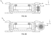
- a rectangular connector is illustrated, in accordance with various embodiments.
- the rectangular connector 302 may be designed to fit inside the outer profile of wall 304 of the roller tray 120.
- a circular connector is illustrated, in accordance with various embodiments.
- circular connector 306 may use mounting distance D from the outer profile of wall 304 of the roller tray 120, which may expose the circular connector 306 to damage during installation, transportation, and storage.
- a shield or cover is provided that attaches to the roller tray 120 to protect the connector.
- Quick-attach splice 400 may be used in conjunction with or instead of quick-connect fittings 150 described above.
- a first roller tray 402 and a second roller tray 404 are placed end to end to form a longer roller tray section in a longitudinal direction (e.g., the x-axis).
- First and second roller trays 402, 404 may be examples of roller trays 120 described above with respect to FIGS. 2A and 2B .
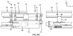
- Quick-attach splice 400 includes a pivoting splice 410. In FIG. 4A , the pivoting splice 410 is in an unattached lowered position.
- the pivoting splice 410 is in a raised position and with first and second roller trays 402 and 404 positioned end-to-end.
- the pivoting splice 410 is in an attached lowered, locked, position.
- pivoting splice 410 includes side rails 420, one or more cross members 422, pins 424, and tabs 426.
- Side rails 420 extend parallel to first and second roller trays 402 and 404 (e.g., in the x-axis).
- cross members 422 extend between side rails 420, from one side rail 420 to the other side rail 420.
- each pin 424 extends from within one cross member 422, through one side rail 420, and past side rail 420 (e.g., in the y-axis).
- each pin 424 is aligned with hole 418 in each side rail 420.
- first roller tray 402 and second roller tray 404 when locked, are firmly connected, allowing forces to pass from first roller tray 402 to second roller tray 404, and vice-versa, providing improved structural integrity and support. Additionally, in various embodiments, first roller tray 402 and second roller tray 404 may be connected using quick-attach splice 400 at any point within cargo compartment 12 and along cargo deck 18 because all connections are located within first and second roller trays 402, 404 of the quick-attach splice 400.
- cross member 422 further includes tabs 426.
- tabs 426 are configured to retract pin 424 into cross member 422 when pulled toward the center of cross member 422 (e.g., in the y-direction).
- each pair of tabs 426 may be pulled together, toward the center of cross member 422, to release the associated pins into the holes 518 or to retract the associate pins 424 from holes 418.
- tabs 426 may be spring-loaded and biased away from the center of cross member 422, that is, away from each other. In various embodiments, this bias keeps pins 424 secured in holes 418 when locked.
- pivoting splice 410 may pivot about cross member 422a to move into the unlocked, or raised, position, as illustrated in FIG. 4B .
- pins 424 in cross member 422a are secured in place by tightening, in a z-direction, tabs 426 securely to cross member 422.
- pivoting splice 410 may be easily removed from both first and second roller trays 402, 404.
- one or more of tabs 426 on pins 424 may be replaced with tool operated pins.
- first roller tray 402 may be removed.
- first roller tray 402 may be moved laterally (e.g., the y-direction) or longitudinally (e.g., the x-direction) before being removed.
- second roller tray 404 may be moved laterally (e.g., the y-direction) or longitudinally (e.g., the x-direction) before being removed.
- pivoting splice 410 further includes roller 430.
- roller 430 extends between side rails 420, from one side rail 420 to the other side rail 420.
- the roller 430 within the pivoting splice 410 reduces roller pitch between roller in first roller tray 402 and rollers in second roller tray 404.
- pivoting splice 410 further includes connector shield 432.
- the connector shield 432 may be coupled to a portion of the pivoting splice 410.
- the connector shield 432 may be coupled to one of the side rails 420.
- the connector shield 432 pivots with the pivoting splice 410, thereby allowing access to the connectors 406a and 406b, such as rectangular connector 302 or circular connector 306 of FIGS. 3A and 3B , when the pivoting splice 410 is pivoted out the way and protects a connection made by connectors 406a and 406b when the pivoting splice 410 is in an attached, lowered, and locked position.
- the connector 406b may be rigidly attached to the second roller tray 404 via, for example, a bracket, while the connector 406a moves freely for ease of coupling the connector 406a to the connector 406b.
- tension straps 434 may be configured to couple a bottom of a one side rail 420 to the associated side rail 420 of the first roller tray 402 or the second roller tray 404 to keep the walls together during installation, transportation, and storage.
- Quick-attach splice 500 may be used in conjunction with or instead of quick-connect fittings 150 described above.
- a first roller tray 502 and a second roller tray 504 are placed end to end to form a longer roller tray section in a longitudinal direction (e.g., the x-axis).
- First and second roller trays 502, 504 may be examples of roller trays 120 described above with respect to FIGS. 2A and 2B .
- Quick-attach splice 500 includes a sliding splice 510.
- the sliding splice 510 is in an unattached position.
- FIG. 5B , 5C , and 5B the sliding splice 510 is in an attached, locked, position.
- sliding splice 510 includes side rails 520, fixed cross member 521, pinning cross member 522, pins 524, and tabs 526.
- Side rails 520 extend parallel to first and second roller trays 502 and 504 (e.g., in the x-axis).
- a proximal end 544 of sliding splice 510 may be mechanically affixed to first roller tray 502.
- a first side rail 520 may be mechanically affixed to a first side structure 502a of first roller tray 502 and a second side rail 520 may be mechanically affixed to a second side structure 502b of first roller tray 502.
- fixed cross member 521 and pinning cross member 522 extend between side rails 520, from one side rail 520 to the other side rail 520.
- each pin 524 extends from within pinning cross member 522, through one side rail 520, and past side rail 520 (e.g., in the y-axis).
- each pin 524 is aligned with hole 518 in each side rail 520.
- each of the side rails 520 include a notch 536 at a distal end 546 of the side rail 520 that slidably engages with cross member 538 of second roller tray 504.
- cross member 538 may be configured to couple one side rail 520 to the associated side rail 520 of the first roller tray 502 or the second roller tray 504 to keep the walls together during installation, transportation, and storage.
- cross member 538 extends between side walls 540, from one side rail 520 to the other side rail 520 and is fixedly coupled to each of the side walls 540 of second roller tray 504.
- first roller tray 502 and second roller tray 504 are firmly connected allowing forces to pass from first roller tray 502 to second roller tray 504, and vice-versa, providing improved structural integrity and support.
- first roller tray 502 and second roller tray 504 may be connected using quick-attach splice 500 at any point within cargo compartment 12 and along cargo deck 18 because all connections are located within first and second roller trays 502, 504 of the quick-attach splice 500.
- pinning cross member 522 further includes tabs 526.
- tabs 526 are configured to retract pin 524 into pinning cross member 522 when pulled toward the center of pinning cross member 522 (e.g., in the y-direction).
- each pair of tabs 526 may be pulled together, toward the center of pinning cross member 522 release the associated pins into the holes 518 or to retract the associate pins 524 from holes 518.
- tabs 526 may be spring-loaded and biased away from the center of pinning cross member 522, that is, away from each other. In various embodiments, this bias keeps pins 524 secured in holes 518 when locked.
- sliding splice 410 along with first roller tray 502 may be slid away from second roller tray 504.
- pins 524 in pinning cross member 522 are secured in place by tightening, in a z-direction, tabs 526 securely to pinning cross member 522.
- one or more of tabs 526 on pins 524 may be replaced with tool operated pins.
- first roller tray 502 may be removed.
- first roller tray 402 may initially be moved laterally (e.g., the y-direction) and then longitudinally (e.g., the x-direction).
- second roller tray 504 may either be moved laterally (e.g., the y-direction) or longitudinally (e.g., the x-direction) before being removed if second roller tray 504 is not coupled to another roller tray or initially moved laterally (e.g., the y-direction) and then longitudinally (e.g., the x-direction) if second roller tray 504 is coupled to another roller tray.
- sliding splice 510 further includes roller 530.
- roller 530 extends between side rails 520, from one side rail 520 to the other side rail 520.
- the roller 530 within the sliding splice 510 reduces roller pitch between roller in first roller tray 502 and rollers in second roller tray 504.
- sliding splice 510 further includes connector shield 542a, 542b.
- the connector shield 542a may be at least one of permanently or non-permanently coupled to a portion of the sliding splice 510, while connector shield 542b may be at least one of permanently or non-permanently coupled to a side wall 540 of second roller tray 504.
- the connector shield 542a may be at least one of permanently or non-permanently coupled to one of the side rails 520.
- the connector shield 542a utilizes a slide pin or other retaining mechanism to allow the connector shield 542a to slide separately from sliding splice 510 thereby allowing access to the connectors 506a and 506b, such as rectangular connector 302 or circular connector 306 of FIGS. 3A and 3B .
- the connector shield 542a may also be removable.
- connector shield 542a when the sliding splice 510 is in an unattached position and slid away from second roller tray 504, connector shield 542a protects connector 506a and connector shield 542b protects connector 506b.
- connector shields 542a and 542b protects a connection made by connectors 506a and 506b.
- the connector 506b may be rigidly attached to the second roller tray 504 via, for example, a bracket, while the connector 506a moves freely for ease of coupling the connector 506a to the connector 506b.
Landscapes
- Engineering & Computer Science (AREA)
- Aviation & Aerospace Engineering (AREA)
- Architecture (AREA)
- Civil Engineering (AREA)
- Structural Engineering (AREA)
- Connection Of Plates (AREA)
Abstract
Description
- The present disclosure relates to cargo handling systems, and more specifically, to tray connections with compact wire routing for convertible aircraft cargo handling systems.
- Today's rapidly evolving and uncertain world has driven the need for increased flexibility and modularity into modern aircraft cargo handling systems. The response to these requirements has led to the development of many "convertible" cargo handling systems that can be easily reconfigured to handle many different mission profiles including bulk cargo, passengers, containerized cargo, additional fuel tanks, etc. One typical implementation of this type of system utilizes discrete floor fittings attached to an aircraft structure to provide standardized quick-attach interfaces for the cargo system components.
- A quick attach splice is provided. The quick attach splice includes a first side rail, a second side rail that is parallel to the first side rail, a cross member extending from the first side rail to the second side rail, a first pin extending from within the cross member and through at least one of the first side rail or the second side rail, a tab configured to retract the first pin, and a roller extending from the first side rail to the second side rail.
- In various embodiments, the quick attach splice further includes a base including a first side structure and a second side structure, and a first hole formed in at least one of the first side structure or the second side structure and configured to receive the first pin. In various embodiments, the quick attach splice further includes a second cross member extending between the first side rail and the second side rail, and a second pin extending from within the second cross member, at least one of the first side rail or the second side rail, and into a second hole formed in at least one of the first side structure or the second side structure and configured to receive the second pin, where the first side rail and the second side rail pivot about the second cross member.
- In various embodiments, the quick attach splice further includes a base including a first side structure and a second side structure, where a first proximal end of the first side rail is affixed to the first side structure and where a second proximal end of the second side rail is affixed to the second side structure. In various embodiments, each of a first distal end of the first side rail and a second distal end of the second side rail include a notch. In various embodiments, the quick attach splice further includes a second cross member extending between the first side rail to the second side rail, and a second pin extending from within the second cross member and through at least one of the first side rail or the second side rail.
- In various embodiments, the tab is a spring-loaded tab biasing the first pin to an extended position. In various embodiments, the quick attach splice further includes a second pin extending from within the cross member and through at least one of the first side rail or the second side rail of which the first pin is not extending. In various embodiments, the quick attach splice, further includes a connector shield, where the connector shield is coupled to at least one of the first side rail or the second side rail and is configured to pivot to allow access to one or more connectors when the quick attach splice is in a raised position and protect the one or more connectors when the quick attach splice is in a lowered position. In various embodiments, the quick attach splice further includes a connector shield, where the connector shield is at least one of permanently or non-permanently coupled to at least one of the first side rail or the second side rail and is configured to slide to allow access to one or more connectors when the quick attach splice is in an unattached position and protect the one or more connectors when the quick attach splice is in an attached position.
- Also provided herein is a cargo handling system. The cargo handling system includes a first tray having a first end, a second tray having a second end, and a quick attach splice configured the connect the first end to the second end. The quick attach splice includes a first side rail, a second side rail that is parallel to the first side rail, a cross member extending from the first side rail to the second side rail, a first pin extending from within the cross member and through at least one of the first side rail or the second side rail, a tab configured to retract the first pin, and a roller extending from the first side rail to the second side rail.
- In various embodiments, the first tray includes a first side structure, a second side structure, and a first hole formed in at least one of the first side structure of the first tray or the second side structure of the first tray and configured to receive the first pin. In various embodiments, the quick attach splice further includes a second cross member extending between the first side rail and the second side rail, and a second pin extending from within the second cross member, through at least one of the first side rail or the second side rail, and into a second hole formed in at least one of the first side structure or the second side structure and configured to receive the second pin, where the first side rail and the second side rail pivot about the second cross member. In various embodiments, the quick attach splice further includes a second cross member extending from the first side rail to the second side rail, and a second pin extending from within the second cross member, through the first side rail, and into a second hole in the second tray, where the first pin is configured to lock into the first tray and the second pin is configured to lock into the second tray.
- In various embodiments, the first tray includes a first side structure, and a second side structure, where a first proximal end of the first side rail is affixed to the first side structure of the first tray and where a second proximal end of the second side rail is affixed to the second side structure of the first tray. In various embodiments, the second tray includes a first side structure, and a second side structure, where each of a first distal end of the first side rail and a second distal end of the second side rail include a notch configured to couple to a second cross member extending between the first side rail of the second tray and the second side structure of the second tray. In various embodiments, the quick attach splice further includes a second cross member extending between the first side rail to the second side rail, and a second pin extending from within the second cross member, the at least one of the first side rail or the second side rail, and into a first hole in the second tray.
- In various embodiments, the tab is a spring-loaded tab biasing the first pin to an extended position. In various embodiments, the quick attach splice further includes a connector shield, where the connector shield is coupled to at least one of the first side rail or the second side rail and is configured to pivot to allow access to one or more connectors when the quick attach splice is in a raised position and protect the one or more connectors when the quick attach splice is in a lowered position. In various embodiments, the quick attach splice further includes a connector shield, where the connector shield is at least one of permanently or non-permanently coupled to at least one of the first side rail or the second side rail and is configured to slide to allow access to one or more connectors when the quick attach splice is in an unattached position and protect the one or more connectors when the quick attach splice is in an attached position.
- The subject matter of the present disclosure is particularly pointed out and distinctly claimed in the concluding portion of the specification. A more complete understanding of the present disclosure, however, may best be obtained by referring to the detailed description and claims when considered in connection with the drawing figures, wherein like numerals denote like elements.
-
FIG. 1 illustrates a schematic view of an aircraft being loaded with cargo, in accordance with various embodiments. -
FIG. 2A illustrates an assembly view of a convertible cargo handling assembly, in accordance with various embodiments. -
FIG. 2B illustrates a convertible cargo handling assembly configured for handling containerized cargo, in accordance with various embodiments. -
FIG. 3A illustrates a rectangular connector, in accordance with various embodiments. -
FIG. 3B illustrates a circular connector in accordance with various embodiments -
FIGS. 4A ,4B, and 4C illustrate a quick-attach splice, in accordance with various embodiments. -
FIGS. 5A, 5B ,5C, and 5D illustrate a quick-attach splice, in accordance with various embodiments. - The following detailed description of various embodiments herein makes reference to the accompanying drawings, which show various embodiments by way of illustration. While these various embodiments are described in sufficient detail to enable those skilled in the art to practice the disclosure, it should be understood that other embodiments may be realized and that changes may be made without departing from the scope of the invention as defined by the claims. Thus, the detailed description herein is presented for purposes of illustration only and not of limitation. Furthermore, any reference to singular includes plural embodiments, and any reference to more than one component or step may include a singular embodiment or step. Also, any reference to attached, fixed, connected, or the like may include permanent, removable, temporary, partial, full or any other possible attachment option. Additionally, any reference to without contact (or similar phrases) may also include reduced contact or minimal contact. It should also be understood that unless specifically stated otherwise, references to "a," "an" or "the" may include one or more than one and that reference to an item in the singular may also include the item in the plural. Further, all ranges may include upper and lower values and all ranges and ratio limits disclosed herein may be combined.
- In typical convertible cargo handling systems the quick-attach scheme attaching the roller trays to the floor fittings provides for easy install/uninstall/upgrade of the convertible cargo handling system when desired. In addition to the floor fittings, the convertible cargo handling systems also uses quick-connect attachment mechanisms between components within the system. One such attachment mechanism is a splice mechanism used to join two separate roller trays.
- A first issue with typical splice mechanisms is an amount of space such splice mechanisms occupy within the roller tray. In typical cargo systems, the roller trays hold several different types of components such as power drive units (PDUs), restraints, rollers, or floor fittings, among others. Fitting all these components into a roller tray while maintaining a proper pitch between rollers may become a complicated task, especially in a narrowbody cargo system where there is only one lane of roller trays. To aid in layout process for a roller tray it is advantageous for these components to occupy the least amount of space possible in the roller tray. Typical splice mechanisms may not be optimized for length, especially when roller trays are installed in a sliding process that use tension straps adjacent to the splice to ensure that the walls of the roller tray do not split apart when the splice is loaded, which may cause slide pins associated with the splice mechanism to become disengaged.
- Another issue with typical splice mechanisms is associated with above-floor wiring that is mounted to the roller trays that the splice mechanisms are joining. With a wire harnesses attached to the roller trays, a break in those roller trays may be in need of a set of mating connectors to allow disconnection of the wire harness. Typical splice mechanisms may not provide a reasonable mechanism for mounting such mating connectors and wiring harnesses and protecting these mating connectors and wiring harnesses from damage.
- A cargo system may have harsh and abusive operating conditions. Thus, it is not desirable to have protruding members from the roller trays that may allow snagging or other damage. Typical splice mechanisms do not allow for a mounting scheme that fully avoids this concern without adding considerable expense.
- Disclosed herein are improved tray connections with compact wire routing for use with a convertible cargo handling system. In various embodiments, an improved splice mechanism provide for an additional roller that may reduce concerns associated with adequate roller pitch in the convertible cargo handling system. In various embodiments, space created by biasing the improved splice mechanism to one side of the track allows for a larger, less expensive, and more commercially available mating connector to be utilized without the mating connector protruding outside the roller tray, thereby reducing a risk of damage to the mating connection and/or the wiring harness associated with the mating connector. In various embodiments, although a pivoting splice mechanism may be attached to either of the two roller trays that are to be coupled together, having the pivoting splice mechanism attached to a same side as a free-floating mating connector is advantageous because an additional connector shield provides additional protection during transportation and storage. In various embodiments, having the connector shield retained on the same side with the free connector end is advantageous because the connector shield acts to capture the free end during storage/transport, which may also ensure that the connector shield is not lost during transportation and storage. In various embodiments, the improved splice mechanism may also protect external connections from the harness to a roller tray structure. In that regard, in various embodiments, some wiring harnesses use ground connections to be connected directly to the roller tray structure. Accordingly, in various embodiments, the connector shield may protect such ground connections.
- With reference to
FIG. 1 , anaircraft 10 is illustrated having acargo compartment 12. Acargo door 14 provides access tocargo compartment 12 from outside theaircraft 10. Cargo 16 (e.g., pallets, ULDs, luggage, etc.) may be loaded and unloaded throughcargo door 14 and onto acargo deck 18 ofaircraft 10. In various embodiments,cargo deck 18 of the cargo system may be equipped with one or more power drive units (PDUs) configured to propel thecargo 16 acrosscargo deck 18 in a desired direction. - With reference to
FIGS. 2A and2B , a convertiblecargo handling assembly 100, which may be located withincargo compartment 12, is illustrated. In accordance with various embodiments, convertiblecargo handling assembly 100 may be converted between a containerized mode (FIG. 2B ), configured to handle containerized cargo, and a bulk mode for handling bulk cargo items individually. Convertiblecargo handling assembly 100 comprises a plurality of floor panels, orpanels 102.Panels 102 may line thecargo compartment 12. For example,panels 102 are located along the floor and walls ofcargo compartment 12.Panels 102 are located overaircraft frame structures 140. In this regard,panels 102 may form thecargo deck 18, with momentary reference toFIG. 1 . In various embodiments, convertiblecargo handling assembly 100 includes components configured to facilitate translation of containerized cargo overpanels 102. For example, convertiblecargo handling assembly 100 may includeball mats 110,roller trays 120, and guide rails 130.Ball mats 110 may be locatedproximate cargo door 14, with momentary reference toFIG. 1 . Convertiblecargo handling assembly 100 may be equipped with one or more power drive units (PDUs) 124a and 124b configured to propel containerized cargo in a desired direction. PDUs 124a may be located inroller trays 120 and PDUs 124b may be located inball mats 110. In various embodiments, PDUs 124a and 124b may be mounted inside of their own, separate structure, outside ofball mats 110 androller trays 120. As discussed in further detail below,ball mats 110,roller trays 120, andguide rails 130 are each removably coupled toaircraft frame structures 140 via one or more quick-connect fitting(s) 150. - Quick-connect
fittings 150 each include a fixedportion 152 attached to anaircraft frame structures 140 and one or more coupling component(s) 154 attached to a removable cargo handling component (i.e., attached to aball mat 110, aroller tray 120, or a guide rail 130). In various embodiments, fixedportions 152 may include a series of seat track rails that are installed flush withpanels 102 providing a similar interface as quick-connect fittings 150 in long continuous rails instead of discrete fittings. Thecoupling components 154 may rotate relative to, axially engage, slide in to, or form a threaded engagement with, the fixedportion 152 to secureball mats 110,roller trays 120, andguide rails 130 to fixedportions 152 andaircraft frame structures 140.Fixed portions 152 are located within openings defined bypanels 102. When convertiblecargo handling assembly 100 is in a containerized mode (FIG. 2B ),ball mats 110,roller trays 120, andguide rails 130 are attached to fixedportions 152. When convertiblecargo handling assembly 100 is in the containerized mode, at least a portion of eachball mat 110,roller tray 120, andguide rails 130 is located on and/or overlaps surface 103 ofpanels 102. When convertiblecargo handling assembly 100 is in a bulk mode,ball mats 110,roller trays 120, andguide rails 130 are removed fromcargo compartment 12, while fixedportions 152 andpanels 102 remain attached. In various embodiments,ball mats 110,roller trays 120, andguide rails 130 are secured toaircraft frame structures 140 independently of one another. Stated differently, eachball mat 110,roller tray 120, andguide rail 130 is secured via its own dedicated quick-connect fitting 150, as opposed to via a coupling to anadjacent ball mat 110,roller tray 120, and/orguide rail 130. In various embodiments,ball mats 110,roller trays 120, and/orguide rails 130 may be secured toaircraft frame structures 140 solely via quick-connect fittings 150. - In various embodiments, two of
roller trays 120 may be spliced together using a slice mechanism, described in detail hereafter. In various embodiments, to control, power or otherwise communicate with components of each of theroller trays 120, wiring harnesses associated with each of theroller trays 120 may be mounted to theroller trays 120 and a mating connector on one wiring harness of afirst roller tray 120 may be coupled to an associated mating connector on another wiring harness of asecond roller tray 120. In various embodiments, there may be may options for the mating connectors, such as a rectangular connector or a circular connector, among others. - With regard to
FIG. 3A , a rectangular connector is illustrated, in accordance with various embodiments. In various embodiments, therectangular connector 302 may be designed to fit inside the outer profile ofwall 304 of theroller tray 120. With regard toFIG. 3B , a circular connector is illustrated, in accordance with various embodiments. In various embodiments,circular connector 306 may use mounting distance D from the outer profile ofwall 304 of theroller tray 120, which may expose thecircular connector 306 to damage during installation, transportation, and storage. As will be discussed hereafter, in various embodiments a shield or cover is provided that attaches to theroller tray 120 to protect the connector. - Referring now to
FIGS. 4A-4C , in accordance with various embodiments, a quick-attachsplice 400 is illustrated. Quick-attachsplice 400 may be used in conjunction with or instead of quick-connect fittings 150 described above. As depicted, afirst roller tray 402 and asecond roller tray 404 are placed end to end to form a longer roller tray section in a longitudinal direction (e.g., the x-axis). First andsecond roller trays roller trays 120 described above with respect toFIGS. 2A and2B . Quick-attachsplice 400 includes a pivotingsplice 410. InFIG. 4A , the pivotingsplice 410 is in an unattached lowered position. InFIG. 4B , the pivotingsplice 410 is in a raised position and with first andsecond roller trays FIG. 4C , the pivotingsplice 410 is in an attached lowered, locked, position. - In various embodiments, pivoting
splice 410 includes side rails 420, one ormore cross members 422, pins 424, andtabs 426. Side rails 420 extend parallel to first andsecond roller trays 402 and 404 (e.g., in the x-axis). In various embodiments,cross members 422 extend betweenside rails 420, from oneside rail 420 to theother side rail 420. In various embodiments, eachpin 424 extends from within onecross member 422, through oneside rail 420, and past side rail 420 (e.g., in the y-axis). In various embodiments, eachpin 424 is aligned withhole 418 in eachside rail 420. In various embodiments, when locked,first roller tray 402 andsecond roller tray 404 are firmly connected, allowing forces to pass fromfirst roller tray 402 tosecond roller tray 404, and vice-versa, providing improved structural integrity and support. Additionally, in various embodiments,first roller tray 402 andsecond roller tray 404 may be connected using quick-attachsplice 400 at any point withincargo compartment 12 and alongcargo deck 18 because all connections are located within first andsecond roller trays splice 400. - In various embodiments,
cross member 422 further includestabs 426. In various embodiments,tabs 426 are configured to retractpin 424 intocross member 422 when pulled toward the center of cross member 422 (e.g., in the y-direction). In various embodiments, each pair oftabs 426 may be pulled together, toward the center ofcross member 422, to release the associated pins into theholes 518 or to retract the associate pins 424 fromholes 418. In various embodiments,tabs 426 may be spring-loaded and biased away from the center ofcross member 422, that is, away from each other. In various embodiments, this bias keepspins 424 secured inholes 418 when locked. In various embodiments, after retractingpins 424, pivotingsplice 410 may pivot aboutcross member 422a to move into the unlocked, or raised, position, as illustrated inFIG. 4B . In various embodiments, pins 424 incross member 422a are secured in place by tightening, in a z-direction,tabs 426 securely to crossmember 422. In various embodiments, pivotingsplice 410 may be easily removed from both first andsecond roller trays tabs 426 onpins 424 may be replaced with tool operated pins. - As illustrated in
FIG. 4B , in various embodiments, after unlocking the quick-attachsplice 400,first roller tray 402 may be removed. In various embodiments,first roller tray 402 may be moved laterally (e.g., the y-direction) or longitudinally (e.g., the x-direction) before being removed. Similarly, in various embodiments,second roller tray 404 may be moved laterally (e.g., the y-direction) or longitudinally (e.g., the x-direction) before being removed. - In various embodiments, pivoting
splice 410 further includesroller 430. In various embodiments,roller 430 extends betweenside rails 420, from oneside rail 420 to theother side rail 420. In various embodiments, theroller 430 within the pivotingsplice 410 reduces roller pitch between roller infirst roller tray 402 and rollers insecond roller tray 404. - In various embodiments, pivoting
splice 410 further includesconnector shield 432. In various embodiments, theconnector shield 432 may be coupled to a portion of the pivotingsplice 410. In various embodiments, theconnector shield 432 may be coupled to one of the side rails 420. In that regard, in various embodiments, theconnector shield 432 pivots with the pivotingsplice 410, thereby allowing access to theconnectors rectangular connector 302 orcircular connector 306 ofFIGS. 3A and 3B , when the pivotingsplice 410 is pivoted out the way and protects a connection made byconnectors splice 410 is in an attached, lowered, and locked position. In various embodiments, theconnector 406b may be rigidly attached to thesecond roller tray 404 via, for example, a bracket, while theconnector 406a moves freely for ease of coupling theconnector 406a to theconnector 406b. In various embodiments, tension straps 434 may be configured to couple a bottom of a oneside rail 420 to the associatedside rail 420 of thefirst roller tray 402 or thesecond roller tray 404 to keep the walls together during installation, transportation, and storage. - Referring now to
FIGS. 5A-5D , in accordance with various embodiments, a quick-attachsplice 500 is illustrated. Quick-attachsplice 500 may be used in conjunction with or instead of quick-connect fittings 150 described above. As depicted, afirst roller tray 502 and asecond roller tray 504 are placed end to end to form a longer roller tray section in a longitudinal direction (e.g., the x-axis). First andsecond roller trays roller trays 120 described above with respect toFIGS. 2A and2B . Quick-attachsplice 500 includes a slidingsplice 510. InFIG. 5A , the slidingsplice 510 is in an unattached position. InFIG. 5B ,5C , and5B , the slidingsplice 510 is in an attached, locked, position. - In various embodiments, sliding
splice 510 includes side rails 520, fixedcross member 521, pinningcross member 522, pins 524, andtabs 526. Side rails 520 extend parallel to first andsecond roller trays 502 and 504 (e.g., in the x-axis). In various embodiments, aproximal end 544 of slidingsplice 510 may be mechanically affixed tofirst roller tray 502. In that regard, in various embodiments, afirst side rail 520 may be mechanically affixed to afirst side structure 502a offirst roller tray 502 and asecond side rail 520 may be mechanically affixed to asecond side structure 502b offirst roller tray 502. - In various embodiments, fixed
cross member 521 and pinningcross member 522 extend betweenside rails 520, from oneside rail 520 to theother side rail 520. In various embodiments, eachpin 524 extends from within pinningcross member 522, through oneside rail 520, and past side rail 520 (e.g., in the y-axis). In various embodiments, eachpin 524 is aligned withhole 518 in eachside rail 520. In various embodiments, each of the side rails 520 include anotch 536 at adistal end 546 of theside rail 520 that slidably engages withcross member 538 ofsecond roller tray 504. In various embodiments,cross member 538 may be configured to couple oneside rail 520 to the associatedside rail 520 of thefirst roller tray 502 or thesecond roller tray 504 to keep the walls together during installation, transportation, and storage. In that regard,cross member 538 extends betweenside walls 540, from oneside rail 520 to theother side rail 520 and is fixedly coupled to each of theside walls 540 ofsecond roller tray 504. In various embodiments, when locked,first roller tray 502 andsecond roller tray 504 are firmly connected allowing forces to pass fromfirst roller tray 502 tosecond roller tray 504, and vice-versa, providing improved structural integrity and support. Additionally, in various embodiments,first roller tray 502 andsecond roller tray 504 may be connected using quick-attachsplice 500 at any point withincargo compartment 12 and alongcargo deck 18 because all connections are located within first andsecond roller trays splice 500. - In various embodiments, pinning
cross member 522 further includestabs 526. In various embodiments,tabs 526 are configured to retractpin 524 into pinningcross member 522 when pulled toward the center of pinning cross member 522 (e.g., in the y-direction). In various embodiments, each pair oftabs 526 may be pulled together, toward the center of pinningcross member 522 release the associated pins into theholes 518 or to retract the associate pins 524 fromholes 518. In various embodiments,tabs 526 may be spring-loaded and biased away from the center of pinningcross member 522, that is, away from each other. In various embodiments, this bias keepspins 524 secured inholes 518 when locked. In various embodiments, after retractingpins 524, slidingsplice 410 along withfirst roller tray 502 may be slid away fromsecond roller tray 504. In various embodiments, pins 524 in pinningcross member 522 are secured in place by tightening, in a z-direction,tabs 526 securely to pinningcross member 522. In various embodiments, one or more oftabs 526 onpins 524 may be replaced with tool operated pins. - In various embodiments, after unlocking the quick-attach
splice 500,first roller tray 502 may be removed. In various embodiments,first roller tray 402 may initially be moved laterally (e.g., the y-direction) and then longitudinally (e.g., the x-direction). In various embodiments and depending on whethersecond roller tray 504 is coupled to another roller tray,second roller tray 504 may either be moved laterally (e.g., the y-direction) or longitudinally (e.g., the x-direction) before being removed ifsecond roller tray 504 is not coupled to another roller tray or initially moved laterally (e.g., the y-direction) and then longitudinally (e.g., the x-direction) ifsecond roller tray 504 is coupled to another roller tray. - In various embodiments, sliding
splice 510 further includesroller 530. In various embodiments,roller 530 extends betweenside rails 520, from oneside rail 520 to theother side rail 520. In various embodiments, theroller 530 within the slidingsplice 510 reduces roller pitch between roller infirst roller tray 502 and rollers insecond roller tray 504. - In various embodiments, sliding
splice 510 further includesconnector shield connector shield 542a may be at least one of permanently or non-permanently coupled to a portion of the slidingsplice 510, whileconnector shield 542b may be at least one of permanently or non-permanently coupled to aside wall 540 ofsecond roller tray 504. In various embodiments, theconnector shield 542a may be at least one of permanently or non-permanently coupled to one of the side rails 520. In that regard, in various embodiments, theconnector shield 542a utilizes a slide pin or other retaining mechanism to allow theconnector shield 542a to slide separately from slidingsplice 510 thereby allowing access to theconnectors rectangular connector 302 orcircular connector 306 ofFIGS. 3A and 3B . In various embodiments, theconnector shield 542a may also be removable. In various embodiments, when the slidingsplice 510 is in an unattached position and slid away fromsecond roller tray 504,connector shield 542a protectsconnector 506a andconnector shield 542b protectsconnector 506b. In various embodiments, when the slidingsplice 510 is in an attached position and coupled tosecond roller tray 504,connector shields connectors connector 506b may be rigidly attached to thesecond roller tray 504 via, for example, a bracket, while theconnector 506a moves freely for ease of coupling theconnector 506a to theconnector 506b. - Benefits and other advantages have been described herein with regard to specific embodiments. Furthermore, the connecting lines shown in the various figures contained herein are intended to represent exemplary functional relationships and/or physical couplings between the various elements. It should be noted that many alternative or additional functional relationships or physical connections may be present in a practical system. However, the benefits, advantages, solutions to problems, and any elements that may cause any benefit, advantage, or solution to occur or become more pronounced are not to be construed as critical, required, or essential features or elements of the disclosure. The scope of the disclosure is accordingly to be limited by nothing other than the appended claims.
Claims (14)
- A quick attach splice, comprising:a first side rail (520);a second side rail (520), parallel to the first side rail;a cross member (422) extending from the first side rail to the second side rail;a first pin (524) extending from within the cross member and through at least one of the first side rail or the second side rail;a tab configured to retract the first pin; anda roller extending from the first side rail to the second side rail.
- The quick attach splice of claim 1, further comprising:a base including a first side structure and a second side structure; anda first hole (518) formed in at least one of the first side structure or the second side structure and configured to receive the first pin.
- The quick attach splice of claim 2, further comprising:a second cross member extending between the first side rail and the second side rail; anda second pin extending from within the second cross member, at least one of the first side rail or the second side rail, and into a second hole formed in at least one of the first side structure or the second side structure and configured to receive the second pin, wherein the first side rail and the second side rail pivot about the second cross member.
- The quick attach splice of claim 1, further comprising:
a base including a first side structure and a second side structure, wherein a first proximal end of the first side rail is affixed to the first side structure and wherein a second proximal end of the second side rail is affixed to the second side structure. - The quick attach splice of claim 4, wherein each of a first distal end of the first side rail and a second distal end of the second side rail comprise a notch.
- The quick attach splice of claim 4, further comprising:a second cross member extending between the first side rail to the second side rail; anda second pin extending from within the second cross member and through at least one of the first side rail or the second side rail.
- The quick attach splice of any preceding claim, wherein the tab is a spring-loaded tab biasing the first pin to an extended position.
- The quick attach splice of any preceding claim, further comprising:
a second pin extending from within the cross member and through at least one of the first side rail or the second side rail of which the first pin is not extending. - The quick attach splice of any preceding claim, further comprising:
a connector shield (432), wherein the connector shield is coupled to at least one of the first side rail or the second side rail and is configured to pivot to allow access to one or more connectors when the quick attach splice is in a raised position and protect the one or more connectors when the quick attach splice is in a lowered position. - The quick attach splice of any of claims 1 to 8, further comprising:
a connector shield, wherein the connector shield is at least one of permanently or non-permanently coupled to at least one of the first side rail or the second side rail and is configured to slide to allow access to one or more connectors when the quick attach splice is in an unattached position and protect the one or more connectors when the quick attach splice is in an attached position. - A cargo handling system, comprising:a first tray (120) having a first end;a second tray (120) having a second end; anda quick attach splice as claimed in any preceding claim configured the connect the first end to the second end.
- The cargo handling system of claim 11, wherein the first tray comprises:a first side structure;a second side structure; anda first hole formed in at least one of the first side structure of the first tray or the second side structure of the first tray and configured to receive the first pin.
- The cargo handling system of claim 11, wherein the first tray comprises:a first side structure; anda second side structure, wherein a first proximal end of the first side rail is affixed to the first side structure of the first tray and wherein a second proximal end of the second side rail is affixed to the second side structure of the first tray.
- The cargo handling system of claim 13, wherein the second tray comprises:a first side structure; anda second side structure, wherein each of a first distal end of the first side rail and a second distal end of the second side rail comprise a notch configured to couple to a second cross member extending between the first side rail of the second tray and the second side structure of the second tray.
Applications Claiming Priority (1)
| Application Number | Priority Date | Filing Date | Title |
|---|---|---|---|
| US18/309,602 US20240364089A1 (en) | 2023-04-28 | 2023-04-28 | Tray connections with compacte wire routing for convertible aircraft cargo handling systems |
Publications (1)
| Publication Number | Publication Date |
|---|---|
| EP4455004A1 true EP4455004A1 (en) | 2024-10-30 |
Family
ID=90924116
Family Applications (1)
| Application Number | Title | Priority Date | Filing Date |
|---|---|---|---|
| EP24173165.2A Pending EP4455004A1 (en) | 2023-04-28 | 2024-04-29 | Tray connections with compact wire routing for convertible aircraft cargo handling systems |
Country Status (2)
| Country | Link |
|---|---|
| US (1) | US20240364089A1 (en) |
| EP (1) | EP4455004A1 (en) |
Citations (3)
| Publication number | Priority date | Publication date | Assignee | Title |
|---|---|---|---|---|
| US3262588A (en) * | 1963-07-19 | 1966-07-26 | American Mach & Foundry | Cargo handling apparatus |
| US20120132744A1 (en) * | 2009-06-22 | 2012-05-31 | Telair International Gmbh | Locking element |
| US20230116108A1 (en) * | 2021-10-07 | 2023-04-13 | Goodrich Corporation | De-lamination resistant and integrated visual wear indicator tire hub |
Family Cites Families (5)
| Publication number | Priority date | Publication date | Assignee | Title |
|---|---|---|---|---|
| US3377040A (en) * | 1966-12-05 | 1968-04-09 | Boeing Co | Retractable cargo securing device |
| US3778012A (en) * | 1970-02-27 | 1973-12-11 | Republic National Bank Of Dall | Automatic pallet lock |
| US7429157B2 (en) * | 2005-10-13 | 2008-09-30 | Goodrich Corporation | Overrideable guide and vertical restraint for an air cargo system |
| US7731460B2 (en) * | 2006-10-30 | 2010-06-08 | Goodrich Corporation | Self-adjusting ULD loading guide and restraint |
| DE102010017535B4 (en) * | 2010-06-23 | 2018-10-25 | Telair International Gmbh | Fastening device for at least partially securing a first and a second freight item |
-
2023
- 2023-04-28 US US18/309,602 patent/US20240364089A1/en active Pending
-
2024
- 2024-04-29 EP EP24173165.2A patent/EP4455004A1/en active Pending
Patent Citations (3)
| Publication number | Priority date | Publication date | Assignee | Title |
|---|---|---|---|---|
| US3262588A (en) * | 1963-07-19 | 1966-07-26 | American Mach & Foundry | Cargo handling apparatus |
| US20120132744A1 (en) * | 2009-06-22 | 2012-05-31 | Telair International Gmbh | Locking element |
| US20230116108A1 (en) * | 2021-10-07 | 2023-04-13 | Goodrich Corporation | De-lamination resistant and integrated visual wear indicator tire hub |
Also Published As
| Publication number | Publication date |
|---|---|
| US20240364089A1 (en) | 2024-10-31 |
Similar Documents
| Publication | Publication Date | Title |
|---|---|---|
| US8317132B2 (en) | Quick-change fastening system for mounting an element to a fastening structure | |
| US8066458B2 (en) | Air cargo centerline restraint system having restraints mounted over floor joists outside the wingbox area for lateral support | |
| US3906870A (en) | Retractable cargo restraint and center guide for cargo compartments | |
| US8534603B2 (en) | System and method for manufacturing a vehicle cabin | |
| EP2928732B1 (en) | A seat belt buckle presenter assembly | |
| US7988391B2 (en) | Self-locking, overrideable and attenuating cargo guide and restraint | |
| US4457649A (en) | Cargo restrainer with spring-bias latch | |
| US10960980B2 (en) | Side guide, side guide group, cargo deck, aircraft | |
| US20110222983A1 (en) | Roller Assembly System and Method for Installation | |
| US20120037753A1 (en) | Lateral guide, lateral guide assembly, cargo deck | |
| EP3848283B1 (en) | Adjustable restraint assemblies | |
| US20070237598A1 (en) | Coaxially mounted retracting guide and restraint for an air cargo system | |
| EP3640145B1 (en) | Moveable integrated side guide and roller tray assembly for cargo management system | |
| CN108366897A (en) | Improved medical stretcher movement system | |
| US12240587B2 (en) | Aircraft fuselage assembly with a cargo floor assembly | |
| EP0514957A1 (en) | Detachable storage bin system | |
| US20240364089A1 (en) | Tray connections with compacte wire routing for convertible aircraft cargo handling systems | |
| EP3511580A1 (en) | A quick-fastening support device for supporting elements that are to be routed on an associated structure | |
| EP3875362B1 (en) | Cargo restraint assembly | |
| US12269611B2 (en) | Cargo system having bulk and transport configurations | |
| CZ20013386A3 (en) | Method and device for securing horizontally loaded cargo units to a vessel | |
| US20250033777A1 (en) | Aircraft seat with double shear track fitting assembly | |
| US12491998B2 (en) | Tray connections for convertible aircraft cargo handling system | |
| EP4588799A1 (en) | Transport of passengers with reduced mobility | |
| US12337991B2 (en) | Aircraft cargo handling system architecture |
Legal Events
| Date | Code | Title | Description |
|---|---|---|---|
| PUAI | Public reference made under article 153(3) epc to a published international application that has entered the european phase |
Free format text: ORIGINAL CODE: 0009012 |
|
| STAA | Information on the status of an ep patent application or granted ep patent |
Free format text: STATUS: THE APPLICATION HAS BEEN PUBLISHED |
|
| AK | Designated contracting states |
Kind code of ref document: A1 Designated state(s): AL AT BE BG CH CY CZ DE DK EE ES FI FR GB GR HR HU IE IS IT LI LT LU LV MC ME MK MT NL NO PL PT RO RS SE SI SK SM TR |
|
| STAA | Information on the status of an ep patent application or granted ep patent |
Free format text: STATUS: REQUEST FOR EXAMINATION WAS MADE |
|
| 17P | Request for examination filed |
Effective date: 20250429 |
|
| GRAP | Despatch of communication of intention to grant a patent |
Free format text: ORIGINAL CODE: EPIDOSNIGR1 |
|
| STAA | Information on the status of an ep patent application or granted ep patent |
Free format text: STATUS: GRANT OF PATENT IS INTENDED |
|
| INTG | Intention to grant announced |
Effective date: 20260130 |
|
| GRAS | Grant fee paid |
Free format text: ORIGINAL CODE: EPIDOSNIGR3 |
|
| GRAA | (expected) grant |
Free format text: ORIGINAL CODE: 0009210 |
|
| STAA | Information on the status of an ep patent application or granted ep patent |
Free format text: STATUS: THE PATENT HAS BEEN GRANTED |