EP4454995A1 - Outboard motor and boat - Google Patents
Outboard motor and boat Download PDFInfo
- Publication number
- EP4454995A1 EP4454995A1 EP24153180.5A EP24153180A EP4454995A1 EP 4454995 A1 EP4454995 A1 EP 4454995A1 EP 24153180 A EP24153180 A EP 24153180A EP 4454995 A1 EP4454995 A1 EP 4454995A1
- Authority
- EP
- European Patent Office
- Prior art keywords
- gear
- slope
- outboard motor
- oil
- peripheral wall
- Prior art date
- Legal status (The legal status is an assumption and is not a legal conclusion. Google has not performed a legal analysis and makes no representation as to the accuracy of the status listed.)
- Pending
Links
Images


Classifications
-
- B—PERFORMING OPERATIONS; TRANSPORTING
- B63—SHIPS OR OTHER WATERBORNE VESSELS; RELATED EQUIPMENT
- B63H—MARINE PROPULSION OR STEERING
- B63H20/00—Outboard propulsion units, e.g. outboard motors or Z-drives; Arrangements thereof on vessels
- B63H20/14—Transmission between propulsion power unit and propulsion element
-
- B—PERFORMING OPERATIONS; TRANSPORTING
- B63—SHIPS OR OTHER WATERBORNE VESSELS; RELATED EQUIPMENT
- B63H—MARINE PROPULSION OR STEERING
- B63H20/00—Outboard propulsion units, e.g. outboard motors or Z-drives; Arrangements thereof on vessels
- B63H20/001—Arrangements, apparatus and methods for handling fluids used in outboard drives
- B63H20/002—Arrangements, apparatus and methods for handling fluids used in outboard drives for handling lubrication liquids
-
- B—PERFORMING OPERATIONS; TRANSPORTING
- B63—SHIPS OR OTHER WATERBORNE VESSELS; RELATED EQUIPMENT
- B63H—MARINE PROPULSION OR STEERING
- B63H20/00—Outboard propulsion units, e.g. outboard motors or Z-drives; Arrangements thereof on vessels
- B63H20/32—Housings
-
- B—PERFORMING OPERATIONS; TRANSPORTING
- B63—SHIPS OR OTHER WATERBORNE VESSELS; RELATED EQUIPMENT
- B63H—MARINE PROPULSION OR STEERING
- B63H20/00—Outboard propulsion units, e.g. outboard motors or Z-drives; Arrangements thereof on vessels
- B63H20/32—Housings
- B63H2020/323—Gear cases
-
- B—PERFORMING OPERATIONS; TRANSPORTING
- B63—SHIPS OR OTHER WATERBORNE VESSELS; RELATED EQUIPMENT
- B63H—MARINE PROPULSION OR STEERING
- B63H21/00—Use of propulsion power plant or units on vessels
- B63H21/12—Use of propulsion power plant or units on vessels the vessels being motor-driven
- B63H21/17—Use of propulsion power plant or units on vessels the vessels being motor-driven by electric motor
Definitions
- the present invention relates to an outboard motor and a boat that comprises an outboard motor.
- a boat is provided with a hull and an outboard motor mounted to a rear portion of the hull.
- the outboard motor is a device that generates thrust to propel the boat.
- the outboard motor has a drive source, a propeller, and a transmission mechanism that has a propeller shaft and transmits the drive power of the drive source to the propeller.
- an outboard motor including an electric motor having an output shaft arranged along an upper-lower direction, a gear mechanism connected to the output shaft of the electric motor, and a case having a housing chamber accommodating the gear mechanism and oil.
- the gear mechanism has a gear that rotates around a rotation shaft along the upper-lower direction (hereinafter referred to as "a vertical shaft rotation gear”) (see e.g. JP 2016-37256 A ).
- the level of the oil in the housing chamber of the case is comparatively low, and there is a risk that the lubricating effect of the oil may not be sufficient for the rotation of the vertical shaft rotation gear.
- gear mechanisms are common to outboard motors in which a transmission mechanism transmitting power from a drive source (not limited to an electric motor but may be an engine, among others) and having a rotor rotating around a rotation shaft along an upper-lower direction and oil are accommodated in a housing chamber of a case.
- a drive source not limited to an electric motor but may be an engine, among others
- a rotor rotating around a rotation shaft along an upper-lower direction and oil are accommodated in a housing chamber of a case.
- said object is solved by an outboard motor having the features of independent claim 1. Moreover, according to the present invention said object is solved by a boat according to claim 15. Preferred embodiments are laid down in the dependent claims.
- the technology disclosed herein can be implemented in various aspects, including, e.g., an outboard motor, a boat provided with an outboard motor and a hull, among other forms.
- the outboard motor disclosed herein can effectively lift the oil upward in the housing chamber of the case.
- FIG. 1 is a perspective view schematically illustrating a configuration of a boat 10 of a preferred embodiment.
- FIG. 1 and other drawings described below show arrows representing each direction with respect to the position of the boat 10. More specifically, each drawing shows arrows representing the front direction (FRONT), rear direction (REAR), left direction (LEFT), right direction (RIGHT), upper direction (UPPER), and lower direction (LOWER), respectively.
- the front-rear direction, left-right direction, and upper-lower (vertical) direction (first direction) are orthogonal to each other.
- the boat 10 includes a hull 200 and an outboard motor 100.
- the boat 10 has only one outboard motor 100, but the boat 10 may have multiple outboard motors 100.
- the hull 200 is a part of the boat 10 for occupants to ride.
- the hull 200 includes a hull main body 202 including a living space 204, a pilot seat 240 installed in the living space 204, and an operating device 250 installed near the pilot seat 240.
- the operating device 250 is a device for steering the boat and includes, e.g., a steering wheel 252, a shift/throttle lever 254, a joystick 255, a monitor 256, and an input device 258.
- the hull 200 includes a partition wall 220 to partition the rear end of the living space 204 and a transom 210 positioned at the rear end of the hull 200. In the front-rear direction, a space 206 is provided between the transom 210 and the partition wall 220.
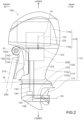
- FIG. 2 is a side view schematically illustrating a configuration of an outboard motor 100 in this embodiment.
- the outboard motor 100 in the reference attitude will be described below unless otherwise specified.
- the reference attitude is an attitude in which the rotation axis Ac of the output shaft 123 of the electric motor 122, which will be described later, extends in the (first) upper-lower direction and the rotation axis Ap of the propeller shaft 137, which will be described later, extends in the front-rear direction.
- the front-rear direction, the left-right direction, and the upper-lower direction are respectively defined based on the outboard motor 100 in the reference attitude.
- the outboard motor 100 is a device that generates thrust to propel the boat 10.
- the outboard motor 100 is attached to the transom 210 at a rear portion of the hull 200.
- the outboard motor 100 includes an outboard motor main body 110 and a suspension device 150.
- the outboard motor main body 110 includes a motor assembly 120, a transmission mechanism 130, a propeller 112, a cowl 114, a casing 116, a water pump 140, and a pump shaft 134.
- the cowl 114 is a housing located on top of the outboard motor main body 110.
- the cowl 114 includes an upper cowl 114a constituting the upper part of the cowl 114 and a lower cowl 114b constituting the lower part of the cowl 114.
- the upper cowl 114a is detachably attached to the lower cowl 114b.
- the casing 116 is a housing located below the cowl 114 and provided in the lower part of the outboard motor main body 110.
- the casing 116 includes a lower case 116b and an upper case 116a.
- the lower case 116b accommodates at least a portion of the drive shaft 133 and the propeller shaft 137 described below.
- the lower case 116b is connected to the upper case 116a so as to be pivotable around the drive shaft 133.
- the upper case 116a is located above the lower case 116b and accommodates a gearbox assembly 300 described below.
- a motor assembly 120 is accommodated within the cowl 114.
- the motor assembly 120 has an electric motor 122.
- the electric motor 122 is an example of the drive source in the claims.
- the electric motor 122 has an output shaft 123 that outputs the drive power generated by the electric motor 122.
- the transmission mechanism 130 is a mechanism that transmits the driving force of the electric motor 122 to the propeller 112. At least a portion of the transmission mechanism 130 is accommodated in the casing 116.
- the transmission mechanism 130 has a gearbox assembly 300, a drive shaft 133, and a propeller shaft 137.
- the propeller shaft 137 is a rod-shaped member and is positioned in a forward and backward extending orientation relatively below the outboard motor main body 110.
- the propeller shaft 137 rotates with the propeller 112.
- the front end of the propeller shaft 137 is accommodated in the lower case 116b, and the rear end of the propeller shaft 137 protrudes rearward from the lower case 116b.
- the front end of the propeller shaft 137 has a gear 138.
- the gearbox assembly 300 is connected to the output shaft 123 of the electric motor 122 and the drive shaft 133.
- the gearbox assembly 300 reduces the driving force of the electric motor 122 and transmits the reduced driving force to the propeller shaft 137. This allows the electric motor 122 to rotate at a desired torque.
- the configuration of the gearbox assembly 300 will be described in detail later.
- the propeller 112 is a rotor with multiple blades and is attached to the rear end of the propeller shaft 137.
- the propeller 112 rotates along with the rotation of the propeller shaft 137 around the rotation axis Ap.
- the propeller 112 generates thrust by rotating.
- the propeller 112 since the lower case 116b is pivotable, the propeller 112 pivots about the drive shaft 133 along with the lower case 116b. Therefore, the boat 10 is steered by pivoting the lower case 116b.
- the water pump 140 pumps water from outside the outboard motor 100, e.g., to cool the electric motor 122.
- the pump shaft 134 extends in an upper-lower direction.
- the pump shaft 134 is driven by the drive power of the electric motor 122 and transmits power to the water pump 140.
- the water pump 140 is driven by the driving force of the electric motor 122 transmitted by the pump shaft 134.
- the suspension device 150 is a device to suspend the outboard motor main body 110 to the hull 200.
- the suspension device 150 includes a pair of left and right clamp brackets 152, a tilt shaft 160, and a swivel bracket 156.
- the pair of left and right clamp brackets 152 are disposed behind the hull 200 in a state separated from each other in the left-right direction and are fixed to the transom 210 of the hull 200 by using, e.g., bolts.
- Each clamp bracket 152 has a cylindrical supporting portion 152a provided with a through-hole extending in the left-right direction.
- the tilt shaft 160 is a rod-shaped member and is rotatably supported within the through-hole in the supporting portion 152a of the clamp bracket 152.
- the tilt axis At which is the centerline of the tilt shaft 160, constitutes the horizontal (left-right) axis in the tilting operation of the outboard motor 100.
- the swivel bracket 156 is positioned so as to be sandwiched between the pair of clamp brackets 152 and is supported by the supporting portion 152a of the clamp brackets 152 via the tilt shaft 160 so as to be rotatable around the tilt axis At.
- the swivel bracket 156 is driven to rotate about the tilt axis At with respect to the clamp bracket 152 by a tilt device (not shown) that includes an actuator, such as a hydraulic cylinder, for example.
- the outboard motor main body 110 supported by the swivel bracket 156 also rotates about the tilt axis At. This achieves the tilting operation of rotating the outboard motor main body 110 in the upper-lower direction with respect to the hull 200.
- the outboard motor 100 can change the angle of the outboard motor main body 110 around the tilt axis At in the range from the tilt-down state in which the propeller 112 is located under the water (the state in which the outboard motor 100 is in the reference attitude) to the tilt-up state in which the propeller 112 is located above the water surface. Trimming operation for adjusting the attitude of the boat 10 during travel can also be performed by adjusting the angle around the tilt axis At of the outboard motor main body 110.
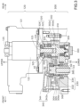
- FIG. 3 is an explanatory view schematically illustrating an internal configuration of a motor assembly 120 and a gearbox assembly 300. As shown in FIG. 3 , the motor assembly 120 and the gearbox assembly 300 are separated from each other and are each accommodated in an individual case.
- the motor assembly 120 includes the electric motor 122 as described above and a motor case 121 that supports the electric motor 122.
- the electric motor 122 is placed vertically in the motor case 121.
- Vertical placement means that the output shaft 123 (rotation axis Ac) of the electric motor 122 is arranged in an attitude in which it extends in the upper-lower direction.
- the upper and lower ends of the output shaft 123 are rotatably supported by a motor bearing 125 fixed to the motor case 121, respectively.
- the gearbox assembly 300 has a primary reduction gear mechanism 310 and a gear case 302.
- the gear case 302 is an example of the case in the claims
- the primary reduction gear mechanism 310 is an example of the gear mechanism in the claims.
- the gear case 302 has a housing chamber R1 that accommodates the primary reduction gear mechanism 310 and oil S.
- the gear case 302 has an upper gear case 302a and a lower gear case 302b combined in the upper-lower direction to form the housing chamber R1.
- the housing chamber R1 includes an input side region R11 and an output side region R12.
- the input side region R11 is the region of the housing chamber R1 that is located directly below the electric motor 122.
- the output side region R12 is a region of the housing chamber R1 that is located forward of the input side region R11.
- the gear case 302 is provided with an input through-hole H1 opening upward from the input side region R11, a through-hole H2 opening downward from the input side region R11, and an output through-hole H3 opening downward from the output side region R12.
- the primary reduction gear mechanism 310 includes an input gear (second gear) 320, an upper input bearing 326, a lower input bearing 350, an output gear (first gear) 330, an upper output bearing 336, and a lower output bearing 337.
- the input gear 320, the upper input bearing 326, and the lower input bearing 350 are accommodated in the input side region R11 of the gear case 302.
- the output gear 330, the upper output bearing 336, and the lower output bearing 337 are accommodated in the output side region R12 of the gear case 302.
- the input gear 320 has an input gear shaft 324 along the upper-lower direction, and the upper end of the input gear shaft 324 is connected to the output shaft 123 of the electric motor 122.
- the input gear 320 is a helical gear.
- the input gear 320 includes an input gear shaft 324 and an input gear body 322 fixed to the input gear shaft 324.
- the input gear body 322 and the input gear shaft 324 may be separated from each other or may be integrally formed.
- the input gear shaft 324 is arranged in an attitude in which it extends along the upper-lower direction.
- An insertion hole 325 is formed in the upper end of the input gear shaft 324.
- the output shaft 123 of the electric motor 122 protrudes into the input side region R11 through the above-mentioned input through-hole H1 of the gear case 302 and is inserted into and fixed to the insertion hole 325 of the input gear shaft 324.
- the input gear 320 rotates integrally with the output shaft 123 around the rotation axis Ac.
- the upper input bearing 326 is located on the upper side of the input gear body 322, is fixed to the gear case 302 (upper gear case 302a), and rotatably supports the upper end of the input gear shaft 324.
- the lower input bearing 350 is located on the lower side of the input gear body 322, is fixed to the gear case 302 (lower gear case 302b), and rotatably supports the lower end of the input gear shaft 324.
- the through-hole H2 of the gear case 302 is sealed by a cap 303.
- the output gear 330 has an output gear shaft 334 along the upper-lower direction and meshes with the input gear 320.
- the output gear 330 is a helical gear.
- the output gear 330 has an output gear shaft 334 and an output gear body 332 fixed to the output gear shaft 334.
- the output gear body 332 and the output gear shaft 334 may be separated from each other or may be integrally formed.
- the output gear shaft 334 is arranged in an attitude in which it extends along the upper-lower direction.
- An insertion hole 345 is formed in the lower end of the output gear shaft 334.
- the drive shaft 133 protrudes into the output side region R12 through the above-mentioned output through-hole H3 of the gear case 302 and is inserted into and fixed to the insertion hole 345 of the output gear shaft 334.
- the output gear 330 rotates integrally with the drive shaft 133.
- the upper output bearing 336 is located on the upper side of the output gear body 332, is fixed to the gear case 302 (upper gear case 302a), and rotatably supports the upper end of the output gear shaft 334.
- the lower output bearing 337 is located on the lower side of the output gear body 332, is fixed to the gear case 302 (lower gear case 302b), and rotatably supports the lower end of the output gear shaft 334.
- the input gear 320 rotates by receiving driving force from the output shaft 123 of the electric motor 122.
- the output gear 330 rotates in conjunction with the input gear 320, and the drive shaft 133 rotates as the output gear 330 rotates.
- the number of teeth of the input gear 320 is greater than that of the output gear 330. Therefore, the drive shaft 133 rotates at a reduced speed relative to the rotational speed of the output shaft 123 by the ratio of the number of teeth of the input gear 320 to the number of teeth of the output gear 330 (reduction ratio).
- the primary reduction gear mechanism 310 transmits the driving force of the electric motor 122 to the drive shaft 133 while reducing the rotational speed of the electric motor 122.
- the primary reduction gear mechanism 310 accommodated in the housing chamber R1 has gears (the input gear 320 and the output gear 330, hereinafter collectively referred to as "vertical shaft rotation gears") that rotate around a rotation shaft along the upper-lower direction.
- gears the input gear 320 and the output gear 330, hereinafter collectively referred to as "vertical shaft rotation gears”
- the lower input bearing 350 and the lower output bearing 337 are both located below the level of the oil S in the housing chamber R1 so that a sufficient lubricating effect of the oil S can be obtained.
- the upper input bearing 326 and the upper output bearing 336 are both located at a position higher than the level of the oil S in the housing chamber R1.
- the upper input bearing 326 can obtain a sufficient lubricating effect of the oil S when the input gear 320 and output gear 330 rotate.
- the upper input bearing 326 is located directly above the tooth meshing position of the input gear 320 and the output gear 330.
- the oil S that leaks out from the tooth meshing position of both gears is also supplied to the upper input bearing 326. Therefore, the upper input bearing 326 can also benefit from the lubrication effect of the oil S.
- the upper output bearing 336 is not located directly above the tooth meshing position of the input gear 320 and output gear 330.
- the tooth meshing position of the input gear 320 and the output gear 330 is located in a position outer than the upper output bearing 336. Therefore, even if the input gear 320 and output gear 330 rotate, sufficient oil S may not be supplied to the upper output bearing 336. Therefore, in this embodiment, the outboard motor 100 is provided with a lifting mechanism for lifting the oil S.
- the upper output bearing 336 is an example of the bearing in the claims.
- the lifting mechanism for lifting the oil S is a mechanism that lifts the oil S in the housing chamber R1 upward by using the rotational force of the vertical shaft rotation gear (output gear 330).
- the lifting mechanism for lifting the oil S has slopes 306a (first slope) and 306b (reverse direction slope) (in FIG. 3 , only the slope 306a is shown) formed in the gear case 302 (lower gear case 302b) and a peripheral wall 304 of the gear case 302.
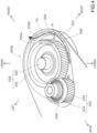
- FIG. 4 is a perspective view schematically illustrating a configuration around slopes 306a, 306b and a peripheral wall 304 of the gear case 302.
- FIG. 4 shows the lower gear case 302b after the upper gear case 302a has been removed, exposing the input gear 320 and the output gear 330 accommodated in the housing chamber R1.
- the peripheral wall 304 is formed to surround the output gear 330 (output gear body 332).
- the inner peripheral surface 305 of the peripheral wall 304 is arcuate when viewed in the upper-lower direction and extends along the rotating direction of the output gear 330.
- the distance between a portion of the inner peripheral surface 305 of the peripheral wall 304 and the output gear body 332 is substantially uniform.
- the slopes 306a, 306b are disposed between the output gear 330 (output gear body 332) and the peripheral wall 304 and are inclined to become higher along the rotating direction of the output gear 330.
- the slope 306a is inclined to become higher along one of the rotating directions of the output gear 330 (in the direction of the white arrow in FIG. 4 ) (in other words, inclined to become continuously higher toward one of the rotating directions).
- the slope 306b is inclined to become higher along the other rotating direction of the output gear 330 (in the direction opposite to the white arrow in FIG. 4 ). This allows the oil S to be lifted upward regardless of whether the output gear 330 is rotating in the forward or reverse direction.
- the slopes 306a, 306b are positioned in the radial direction of the output gear 330 at a distance from the output gear 330. Therefore, compared to a configuration in which the slopes 306a, 306b are adjacent to the output gear 330, the oil S can be lifted upward without affecting the rotation of the output gear 330.
- the slopes 306a, 306b extend along the inner peripheral surface 305 while contacting the inner peripheral surface 305 of the peripheral wall 304. Therefore, compared to a configuration in which the slopes 306a, 306b are slightly separated from the peripheral wall 304 or the slopes 306a, 306b do not extend along the inner peripheral surface 305 of the peripheral wall 304, the oil S can be lifted upward more effectively.
- the inclination angle ⁇ (see FIG. 5 below) of the slopes 306a, 306b relative to the horizontal direction may be, e.g., 80 degrees or less, 70 degrees or less, 60 degrees or less, 45 degrees or less, 40 degrees or less, 30 degrees or less, or 20 degrees or less. It should be noted that a configuration in which the slope angle ⁇ is 45 degrees or less can effectively lift the oil S upward by taking advantage of the momentum of the oil S flow, compared to a configuration in which the slope angle is greater than 45 degrees.
- the lower ends N of the slopes 306a and 306b face the floor surface 308 of the housing chamber R1 (see also FIG. 5 below). Therefore, compared to a configuration in which a step exists between the lower end N of the slopes 306a, 306b and the floor surface 308 of the housing chamber R1, the oil S can flow smoothly into the slopes 306a, 306b so that the oil can S be lifted upward more effectively.
- the slopes 306a, 306b are formed on the side of the output gear 330 opposite to the input gear 320. This allows the oil S to be effectively lifted upward by the momentum of the rotation of the output gear 330 while suppressing the effect of the momentum of the rotation of the input gear 320, which rotates in the opposite direction to the output gear 330.
- the two slopes 306a, 306b are located at different positions from each other on a virtual circle centered on the output gear 330. This can suppress an increase in the size of the housing chamber R1, compared to a configuration in which the two slopes 306a, 306b are arranged to be aligned in the radial direction of the output gear 330.
- the highest end of the slope 306a and the highest end of the slope 306b are at the same height and are flush with each other. Therefore, it is possible to suppress a reduction in the momentum of the flow of the oil S to the other slope 306b due to the presence of the one slope 306a, compared to a configuration in which the two slopes 306a, 306b are arranged in the rotating direction separated from each other, for example.
- the outboard motor 100 further includes a guiding mechanism 340.
- the guiding mechanism 340 is a mechanism that guides the oil S lifted upward by the lifting mechanism (slopes 306a, 306b) described above to the upper output bearing 336.
- the guiding mechanism 340 includes two first introduction tubes 342a, 342b and two second introduction tubes 344.
- FIG. 5 is an explanatory view schematically illustrating a configuration of the slopes 306a, 306b, as seen from the output gear 330 side (rear side).
- one first introduction tube 342a is positioned above the slope 306a and arranged in an attitude in which it extends in the upper-lower direction.
- the one first introduction tube 342a has a lower opening 341a that opens toward the upper side of the slope 306a.
- the other first introduction tube 342b is positioned above the slope 306b and is arranged in an attitude in which it extends in the upper-lower direction.
- the other first introduction tube 342b has a lower opening 341b that opens toward the upper side of the slope 306b.
- the end face 343a at which the lower opening 341a is formed is inclined downward along the rotating direction of the output gear 330 (toward the left side of the paper of FIG. 5 ) that lifts up the oil S by the slope 306a (inclined to become lower along the rotating direction). Therefore, the oil S lifted by the slope 306a is easily introduced into the lower opening 341a of the one first introduction tube 342a.
- the end face 343b at which the lower opening 341b is formed is inclined downward along the rotating direction of the output gear 330 that lifts up the oil S by the slope 306b (toward the right side of the paper of FIG. 5 ). Therefore, the oil S lifted by the slope 306b is easily introduced into the lower opening 341b of the other first introduction tube 342b.
- each second introduction tube 344 is communicatively connected to the upper end of each of the first introduction tubes 342a, 342b, and the other end of each second introduction tube 344 is communicatively connected to the space R2 formed above the upper output bearing 336.
- Each second introduction tube 344 is inclined such that one end of the second introduction tube 344 is lower than the other end. Therefore, the oil S introduced into the second introduction tube 344 from each of the first introduction tubes 342a, 342b flows into the space R2 by its own weight.
- This guiding mechanism 340 can effectively supply the oil S to the upper output bearing 336 that supports the upper end of the output gear shaft 334 of the output gear 330.
- axes, members, and the like extending in the front-rear direction need not necessarily be parallel to the front-rear direction.
- Axes and members extending in the front-rear direction include axes and members that are inclined in the range of ⁇ 45° to the front-rear direction.
- axes and members extending in the upper-lower direction include axes and members inclined within a range of ⁇ 45° to the upper-lower direction
- axes and members extending in the left-right direction include axes and members inclined within a range of ⁇ 45° to the left-right direction.
- the configuration of the boat 10 and outboard motor 100 of the preferred embodiment is only an example and is variously deformable.
- the drive shaft 133 is positioned in front of the output shaft 123, but the drive shaft 133 may be positioned behind the output shaft 123.
- an electric motor 122 with the output shaft 123 disposed along the upper-lower direction is shown as the drive source, but the drive source may be an electric motor with the output shaft 123 disposed along a direction other than the upper-lower direction (e.g., horizontal direction) or an engine such as internal combustion engine.
- a primary reduction gear mechanism 310 is illustrated as the transmission mechanism, but the transmission mechanism is not limited to this but may be a multiple reduction gear, another gear mechanism (such as a speed change mechanism), a winding transmission mechanism (such as a belt mechanism or chain mechanism) with a rotor (such as a pulley or sprocket) rotating around a rotation shaft along an upper-lower direction, or a transmission shaft such as a drive shaft.
- the gear mechanism or the transmission mechanism need only have at least one gear or rotor that rotates around a rotation shaft along the upper-lower direction.
- the input gear 320 and output gear 330 are not limited to the helical gears but may be sprue gears or bevel gears.
- the lifting mechanism for lifting the oil S is configured to have two slopes 306a, 306b, but it may have only one or more than three slopes. Furthermore, in the above embodiment, the lifting mechanism for lifting the oil S may have:
- the above embodiment may be configured such that the guiding mechanism 340 is not provided and the oil S lifted by the slopes 306a, 306b is directly supplied to the output gear 330 and the upper output bearing 336.
- the guiding mechanism 340 is configured to have two first introduction tubes and two second introduction tubes, but at least one of the first and second introduction tubes may be only one or three or more.
- the lower case 116b is connected to the upper case 116a so that the lower case 116b is rotatable, but the lower case 116b does not necessarily have to be rotatable.
- the casing 116 need not have the upper case 116a and the lower case 116b but may be composed of a single member.
- the outboard motor 100 is provided with the water pump 140 as a driven device, but it may not be provided with the water pump 140 or may be provided with another driven device instead of the water pump 140.
Landscapes
- Chemical & Material Sciences (AREA)
- Engineering & Computer Science (AREA)
- Combustion & Propulsion (AREA)
- Mechanical Engineering (AREA)
- Ocean & Marine Engineering (AREA)
- General Details Of Gearings (AREA)
Abstract
Description
- The present invention relates to an outboard motor and a boat that comprises an outboard motor.
- A boat is provided with a hull and an outboard motor mounted to a rear portion of the hull. The outboard motor is a device that generates thrust to propel the boat. The outboard motor has a drive source, a propeller, and a transmission mechanism that has a propeller shaft and transmits the drive power of the drive source to the propeller.
- There has been disclosed an outboard motor including an electric motor having an output shaft arranged along an upper-lower direction, a gear mechanism connected to the output shaft of the electric motor, and a case having a housing chamber accommodating the gear mechanism and oil. The gear mechanism has a gear that rotates around a rotation shaft along the upper-lower direction (hereinafter referred to as "a vertical shaft rotation gear") (see e.g.
JP 2016-37256 A - In the outboard motor of the above conventional technology, in which the vertical shaft rotation gear and oil are accommodated in the housing chamber of the case, the level of the oil in the housing chamber of the case is comparatively low, and there is a risk that the lubricating effect of the oil may not be sufficient for the rotation of the vertical shaft rotation gear.
- These issues are not limited to gear mechanisms but are common to outboard motors in which a transmission mechanism transmitting power from a drive source (not limited to an electric motor but may be an engine, among others) and having a rotor rotating around a rotation shaft along an upper-lower direction and oil are accommodated in a housing chamber of a case.
- It is the object of the present invention to provide an outboard motor and a boat that comprises an outboard motor wherein sufficient lubricating effect of oil can be ensured.
- According to the present invention said object is solved by an outboard motor having the features of independent claim 1. Moreover, according to the present invention said object is solved by a boat according to claim 15. Preferred embodiments are laid down in the dependent claims.
- The technology disclosed herein can be implemented in the following aspects.
- (1) An outboard motor according to an aspect of the present disclosure includes: an electric motor having an output shaft arranged along an upper-lower direction; a gear mechanism connected to the output shaft of the electric motor and having gears rotating around a rotation shaft along the upper-lower direction; and a housing chamber accommodating the gear mechanism and oil, wherein the housing chamber of the case is provided with a peripheral wall disposed around the gear and a slope disposed between the gear and the peripheral wall and inclined to become higher along the rotating direction of the gear. In this outboard motor, the peripheral wall is arranged around the vertical shaft rotation gear and the slope is arranged between the vertical shaft rotation gear and the peripheral wall. This slope is inclined to become higher along the rotating direction of the vertical shaft rotation gear. This causes the oil to flow toward one side of the rotating direction as the vertical shaft rotation gear rotates, and the momentum of the flow lifts some of the oil upward along the slope. This lifted oil is applied to the upper side of the vertical shaft rotation gear, which improves the lubricating effect of the oil, e.g., on the rotation of the vertical shaft rotation gear.
- (2) In the above outboard motor, the inner peripheral surface of the peripheral wall may be configured to be arc-shaped, extending along the rotating direction of the gear when viewed in the upper-lower direction. According to this outboard motor, compared to a configuration in which the inner peripheral surface of the peripheral wall extends in a direction different from the rotating direction of the vertical shaft rotation gear, the momentum of the oil flow with the rotation of the vertical shaft rotation gear is higher so that the oil can be effectively lifted upward.
- (3) In the above outboard motor, the slope may be configured to be positioned at a distance from the gear in the radial direction of the gear. This outboard motor can lift the oil upward without affecting the rotation of the vertical shaft rotation gear, compared to a configuration in which the slope is adjacent to the vertical shaft rotation gear.
- (4) In the above outboard motor, the slope may be configured to extend along the inner peripheral surface of the peripheral wall while contacting the inner peripheral surface of the peripheral wall. This outboard motor can lift the oil upward more effectively, compared to a configuration in which the slope is slightly separated from the peripheral wall or the slope does not extend along the inner peripheral surface of the peripheral wall.
- (5) In the above outboard motor, the slope may be configured to have an inclination angle of 45 degrees or less with respect to the horizontal direction. This outboard motor can effectively lift the oil upward by utilizing the momentum of the oil flow, compared to a configuration in which the slope inclination angle with respect to the horizontal direction is greater than 45 degrees.
- (6) In the above outboard motor, the lower end of the slope may be configured to face the floor surface of the housing chamber. According to this outboard motor, oil flows smoothly into the slope so that the oil can be lifted upward more effectively, compared to a configuration in which a step exists between the lower end of the slope and the floor surface of the housing chamber.
- (7) In the above outboard motor, the gear mechanism may be configured to have another gear meshing with the gear, and the slope may be formed on the opposite side of the gear to the other gear. This outboard motor can lift the oil above the gear more securely, compared to a configuration in which the upper end of the slope is located below the upper surface of the gear.
- (8) In the above outboard motor, the housing chamber of the case may be configure to further include a reverse direction slope disposed between the gear and the peripheral wall and inclined to become higher along the rotating direction of the gear that is opposite to the slope. This outboard motor can lift the oil upward regardless of whether the vertical shaft rotation gear is rotating in the forward or reverse direction.
- (9) In the above outboard motor, the slope and the reverse direction slope may be configured to be located at different positions on a virtual circle centered on the gear. This outboard motor can suppress an increase in the size of the housing chamber, compared to a configuration in which the slope and the reverse direction slope are arranged to be aligned in the radial direction of the vertical shaft rotation gear.
- (10) In the above outboard motor, the highest end of the slope and the highest end of the reverse direction slope may be configured to be flush with each other. This outboard motor can suppress a reduction in the momentum of the oil flow due to the presence of the slope and the reverse direction slope, compared to a configuration in which the slope and the reverse direction slope are arranged in the rotating direction at a distance from each other, for example.
- (11) The above outboard motor may be configured to further include a bearing supporting the upper end of the gear shaft of the gear and a guiding mechanism that guides the oil lifted by the slope to the bearing. This outboard motor can effectively supply the oil to the bearing supporting the upper end of the gear shaft of the gear.
- (12) In the above outboard motor, the gear mechanism may be configured as a reduction gear mechanism connected to the output shaft of the electric motor and having an input gear meshing with the gear. This outboard motor can lift the oil above the gear in the reduction gear.
- (13) The above outboard motor may be configured to further include a bearing supporting the upper end of the gear shaft of the gear and a guiding mechanism guiding the oil lifted by the slope to the bearing, wherein the position at which the gear meshes with the input gear is located on the circumference side outer than the bearing when viewed in the upper-lower direction. This outboard motor can effectively supply the oil to the bearing supporting the upper end of the gear shaft of the gear.
- (14) An outboard motor according to another aspect of the present disclosure includes: a drive source; a transmission mechanism transmitting power from the drive source and having a rotor rotating around a rotation shaft along an upper-lower direction; and a case having a housing chamber accommodating the transmission mechanism and oil, wherein the housing chamber of the case is provided with a peripheral wall disposed around the rotor and a slope disposed between the rotor and the peripheral wall and inclined to become higher along the rotating direction of the rotor. This outboard motor can effectively lift the oil upward.
- The technology disclosed herein can be implemented in various aspects, including, e.g., an outboard motor, a boat provided with an outboard motor and a hull, among other forms.
- The outboard motor disclosed herein can effectively lift the oil upward in the housing chamber of the case.
-
-
FIG. 1 is a perspective view schematically illustrating a configuration of aboat 10 in an embodiment. -
FIG. 2 is a side view schematically illustrating a configuration of anoutboard motor 100 in the embodiment. -
FIG. 3 is an explanatory view schematically illustrating an internal configuration of amotor assembly 120 and agearbox assembly 300. -
FIG. 4 is a perspective view schematically illustrating a configuration aroundslopes peripheral wall 304 of agear case 302. -
FIG. 5 is an explanatory view schematically illustrating a configuration of theslopes output gear 330 side. -
FIG. 1 is a perspective view schematically illustrating a configuration of aboat 10 of a preferred embodiment.FIG. 1 and other drawings described below show arrows representing each direction with respect to the position of theboat 10. More specifically, each drawing shows arrows representing the front direction (FRONT), rear direction (REAR), left direction (LEFT), right direction (RIGHT), upper direction (UPPER), and lower direction (LOWER), respectively. The front-rear direction, left-right direction, and upper-lower (vertical) direction (first direction) are orthogonal to each other. - The
boat 10 includes ahull 200 and anoutboard motor 100. In this embodiment, theboat 10 has only oneoutboard motor 100, but theboat 10 may havemultiple outboard motors 100. - The
hull 200 is a part of theboat 10 for occupants to ride. Thehull 200 includes a hullmain body 202 including aliving space 204, apilot seat 240 installed in theliving space 204, and anoperating device 250 installed near thepilot seat 240. Theoperating device 250 is a device for steering the boat and includes, e.g., asteering wheel 252, a shift/throttle lever 254, ajoystick 255, amonitor 256, and aninput device 258. Thehull 200 includes apartition wall 220 to partition the rear end of theliving space 204 and atransom 210 positioned at the rear end of thehull 200. In the front-rear direction, aspace 206 is provided between thetransom 210 and thepartition wall 220. -
FIG. 2 is a side view schematically illustrating a configuration of anoutboard motor 100 in this embodiment. Theoutboard motor 100 in the reference attitude will be described below unless otherwise specified. The reference attitude is an attitude in which the rotation axis Ac of theoutput shaft 123 of theelectric motor 122, which will be described later, extends in the (first) upper-lower direction and the rotation axis Ap of thepropeller shaft 137, which will be described later, extends in the front-rear direction. The front-rear direction, the left-right direction, and the upper-lower direction are respectively defined based on theoutboard motor 100 in the reference attitude. - The
outboard motor 100 is a device that generates thrust to propel theboat 10. Theoutboard motor 100 is attached to thetransom 210 at a rear portion of thehull 200. Theoutboard motor 100 includes an outboard motormain body 110 and a suspension device 150. - The outboard motor
main body 110 includes amotor assembly 120, atransmission mechanism 130, apropeller 112, acowl 114, acasing 116, awater pump 140, and apump shaft 134. - The
cowl 114 is a housing located on top of the outboard motormain body 110. Thecowl 114 includes anupper cowl 114a constituting the upper part of thecowl 114 and alower cowl 114b constituting the lower part of thecowl 114. Theupper cowl 114a is detachably attached to thelower cowl 114b. - The
casing 116 is a housing located below thecowl 114 and provided in the lower part of the outboard motormain body 110. Thecasing 116 includes alower case 116b and anupper case 116a. Thelower case 116b accommodates at least a portion of thedrive shaft 133 and thepropeller shaft 137 described below. Thelower case 116b is connected to theupper case 116a so as to be pivotable around thedrive shaft 133. Theupper case 116a is located above thelower case 116b and accommodates agearbox assembly 300 described below. - A
motor assembly 120 is accommodated within thecowl 114. Themotor assembly 120 has anelectric motor 122. Theelectric motor 122 is an example of the drive source in the claims. Theelectric motor 122 has anoutput shaft 123 that outputs the drive power generated by theelectric motor 122. - The
transmission mechanism 130 is a mechanism that transmits the driving force of theelectric motor 122 to thepropeller 112. At least a portion of thetransmission mechanism 130 is accommodated in thecasing 116. Thetransmission mechanism 130 has agearbox assembly 300, adrive shaft 133, and apropeller shaft 137. - The
propeller shaft 137 is a rod-shaped member and is positioned in a forward and backward extending orientation relatively below the outboard motormain body 110. Thepropeller shaft 137 rotates with thepropeller 112. The front end of thepropeller shaft 137 is accommodated in thelower case 116b, and the rear end of thepropeller shaft 137 protrudes rearward from thelower case 116b. The front end of thepropeller shaft 137 has agear 138. - The
gearbox assembly 300 is connected to theoutput shaft 123 of theelectric motor 122 and thedrive shaft 133. Thegearbox assembly 300 reduces the driving force of theelectric motor 122 and transmits the reduced driving force to thepropeller shaft 137. This allows theelectric motor 122 to rotate at a desired torque. The configuration of thegearbox assembly 300 will be described in detail later. - The
propeller 112 is a rotor with multiple blades and is attached to the rear end of thepropeller shaft 137. Thepropeller 112 rotates along with the rotation of thepropeller shaft 137 around the rotation axis Ap. Thepropeller 112 generates thrust by rotating. As mentioned above, since thelower case 116b is pivotable, thepropeller 112 pivots about thedrive shaft 133 along with thelower case 116b. Therefore, theboat 10 is steered by pivoting thelower case 116b. - The
water pump 140 pumps water from outside theoutboard motor 100, e.g., to cool theelectric motor 122. Thepump shaft 134 extends in an upper-lower direction. Thepump shaft 134 is driven by the drive power of theelectric motor 122 and transmits power to thewater pump 140. Thewater pump 140 is driven by the driving force of theelectric motor 122 transmitted by thepump shaft 134. - The suspension device 150 is a device to suspend the outboard motor
main body 110 to thehull 200. The suspension device 150 includes a pair of left and right clamp brackets 152, a tilt shaft 160, and a swivel bracket 156. - The pair of left and right clamp brackets 152 are disposed behind the
hull 200 in a state separated from each other in the left-right direction and are fixed to thetransom 210 of thehull 200 by using, e.g., bolts. Each clamp bracket 152 has a cylindrical supporting portion 152a provided with a through-hole extending in the left-right direction. - The tilt shaft 160 is a rod-shaped member and is rotatably supported within the through-hole in the supporting portion 152a of the clamp bracket 152. The tilt axis At, which is the centerline of the tilt shaft 160, constitutes the horizontal (left-right) axis in the tilting operation of the
outboard motor 100. - The swivel bracket 156 is positioned so as to be sandwiched between the pair of clamp brackets 152 and is supported by the supporting portion 152a of the clamp brackets 152 via the tilt shaft 160 so as to be rotatable around the tilt axis At. The swivel bracket 156 is driven to rotate about the tilt axis At with respect to the clamp bracket 152 by a tilt device (not shown) that includes an actuator, such as a hydraulic cylinder, for example.
- When the swivel bracket 156 rotates about the tilt axis At with respect to the clamp bracket 152, the outboard motor
main body 110 supported by the swivel bracket 156 also rotates about the tilt axis At. This achieves the tilting operation of rotating the outboard motormain body 110 in the upper-lower direction with respect to thehull 200. By this tilting operation, theoutboard motor 100 can change the angle of the outboard motormain body 110 around the tilt axis At in the range from the tilt-down state in which thepropeller 112 is located under the water (the state in which theoutboard motor 100 is in the reference attitude) to the tilt-up state in which thepropeller 112 is located above the water surface. Trimming operation for adjusting the attitude of theboat 10 during travel can also be performed by adjusting the angle around the tilt axis At of the outboard motormain body 110. -
FIG. 3 is an explanatory view schematically illustrating an internal configuration of amotor assembly 120 and agearbox assembly 300. As shown inFIG. 3 , themotor assembly 120 and thegearbox assembly 300 are separated from each other and are each accommodated in an individual case. - The
motor assembly 120 includes theelectric motor 122 as described above and amotor case 121 that supports theelectric motor 122. Theelectric motor 122 is placed vertically in themotor case 121. Vertical placement means that the output shaft 123 (rotation axis Ac) of theelectric motor 122 is arranged in an attitude in which it extends in the upper-lower direction. The upper and lower ends of theoutput shaft 123 are rotatably supported by amotor bearing 125 fixed to themotor case 121, respectively. - The
gearbox assembly 300 has a primaryreduction gear mechanism 310 and agear case 302. Thegear case 302 is an example of the case in the claims, and the primaryreduction gear mechanism 310 is an example of the gear mechanism in the claims. - The
gear case 302 has a housing chamber R1 that accommodates the primaryreduction gear mechanism 310 and oil S. Thegear case 302 has an upper gear case 302a and alower gear case 302b combined in the upper-lower direction to form the housing chamber R1. The housing chamber R1 includes an input side region R11 and an output side region R12. The input side region R11 is the region of the housing chamber R1 that is located directly below theelectric motor 122. The output side region R12 is a region of the housing chamber R1 that is located forward of the input side region R11. Thegear case 302 is provided with an input through-hole H1 opening upward from the input side region R11, a through-hole H2 opening downward from the input side region R11, and an output through-hole H3 opening downward from the output side region R12. - The primary
reduction gear mechanism 310 includes an input gear (second gear) 320, an upper input bearing 326, a lower input bearing 350, an output gear (first gear) 330, anupper output bearing 336, and a lower output bearing 337. Theinput gear 320, the upper input bearing 326, and the lower input bearing 350 are accommodated in the input side region R11 of thegear case 302. Theoutput gear 330, theupper output bearing 336, and the lower output bearing 337 are accommodated in the output side region R12 of thegear case 302. - The
input gear 320 has aninput gear shaft 324 along the upper-lower direction, and the upper end of theinput gear shaft 324 is connected to theoutput shaft 123 of theelectric motor 122. In this embodiment, theinput gear 320 is a helical gear. Specifically, theinput gear 320 includes aninput gear shaft 324 and aninput gear body 322 fixed to theinput gear shaft 324. Theinput gear body 322 and theinput gear shaft 324 may be separated from each other or may be integrally formed. Theinput gear shaft 324 is arranged in an attitude in which it extends along the upper-lower direction. Aninsertion hole 325 is formed in the upper end of theinput gear shaft 324. Theoutput shaft 123 of theelectric motor 122 protrudes into the input side region R11 through the above-mentioned input through-hole H1 of thegear case 302 and is inserted into and fixed to theinsertion hole 325 of theinput gear shaft 324. Thus, theinput gear 320 rotates integrally with theoutput shaft 123 around the rotation axis Ac. - The upper input bearing 326 is located on the upper side of the
input gear body 322, is fixed to the gear case 302 (upper gear case 302a), and rotatably supports the upper end of theinput gear shaft 324. The lower input bearing 350 is located on the lower side of theinput gear body 322, is fixed to the gear case 302 (lower gear case 302b), and rotatably supports the lower end of theinput gear shaft 324. The through-hole H2 of thegear case 302 is sealed by acap 303. - The
output gear 330 has anoutput gear shaft 334 along the upper-lower direction and meshes with theinput gear 320. In this embodiment, theoutput gear 330 is a helical gear. Specifically, theoutput gear 330 has anoutput gear shaft 334 and anoutput gear body 332 fixed to theoutput gear shaft 334. Theoutput gear body 332 and theoutput gear shaft 334 may be separated from each other or may be integrally formed. Theoutput gear shaft 334 is arranged in an attitude in which it extends along the upper-lower direction. Aninsertion hole 345 is formed in the lower end of theoutput gear shaft 334. Thedrive shaft 133 protrudes into the output side region R12 through the above-mentioned output through-hole H3 of thegear case 302 and is inserted into and fixed to theinsertion hole 345 of theoutput gear shaft 334. Thus, theoutput gear 330 rotates integrally with thedrive shaft 133. - The upper output bearing 336 is located on the upper side of the
output gear body 332, is fixed to the gear case 302 (upper gear case 302a), and rotatably supports the upper end of theoutput gear shaft 334. The lower output bearing 337 is located on the lower side of theoutput gear body 332, is fixed to the gear case 302 (lower gear case 302b), and rotatably supports the lower end of theoutput gear shaft 334. - With the above configuration, the
input gear 320 rotates by receiving driving force from theoutput shaft 123 of theelectric motor 122. Theoutput gear 330 rotates in conjunction with theinput gear 320, and thedrive shaft 133 rotates as theoutput gear 330 rotates. Here, in this embodiment, the number of teeth of theinput gear 320 is greater than that of theoutput gear 330. Therefore, thedrive shaft 133 rotates at a reduced speed relative to the rotational speed of theoutput shaft 123 by the ratio of the number of teeth of theinput gear 320 to the number of teeth of the output gear 330 (reduction ratio). Thus, the primaryreduction gear mechanism 310 transmits the driving force of theelectric motor 122 to thedrive shaft 133 while reducing the rotational speed of theelectric motor 122. - As described above, the primary
reduction gear mechanism 310 accommodated in the housing chamber R1 has gears (theinput gear 320 and theoutput gear 330, hereinafter collectively referred to as "vertical shaft rotation gears") that rotate around a rotation shaft along the upper-lower direction. In a configuration in which a gear mechanism with such a vertical shaft rotation gear is accommodated in the housing chamber R1 together with the oil S, there is a risk that the lubricating effect of the oil may not be sufficient for the rotation of the vertical shaft rotation gear. - For example, in the configuration shown in
FIG. 3 , the lower input bearing 350 and the lower output bearing 337 are both located below the level of the oil S in the housing chamber R1 so that a sufficient lubricating effect of the oil S can be obtained. [ - The upper input bearing 326 and the upper output bearing 336 are both located at a position higher than the level of the oil S in the housing chamber R1. Here, the upper input bearing 326 can obtain a sufficient lubricating effect of the oil S when the
input gear 320 andoutput gear 330 rotate. In other words, the upper input bearing 326 is located directly above the tooth meshing position of theinput gear 320 and theoutput gear 330. When theinput gear 320 andoutput gear 330 rotate, the oil S that leaks out from the tooth meshing position of both gears is also supplied to the upper input bearing 326. Therefore, the upper input bearing 326 can also benefit from the lubrication effect of the oil S. - On the other hand, the upper output bearing 336 is not located directly above the tooth meshing position of the
input gear 320 andoutput gear 330. In other words, the tooth meshing position of theinput gear 320 and theoutput gear 330 is located in a position outer than theupper output bearing 336. Therefore, even if theinput gear 320 andoutput gear 330 rotate, sufficient oil S may not be supplied to theupper output bearing 336. Therefore, in this embodiment, theoutboard motor 100 is provided with a lifting mechanism for lifting the oil S. The upper output bearing 336 is an example of the bearing in the claims. - The lifting mechanism for lifting the oil S is a mechanism that lifts the oil S in the housing chamber R1 upward by using the rotational force of the vertical shaft rotation gear (output gear 330). Specifically, the lifting mechanism for lifting the oil S has
slopes 306a (first slope) and 306b (reverse direction slope) (inFIG. 3 , only theslope 306a is shown) formed in the gear case 302 (lower gear case 302b) and aperipheral wall 304 of thegear case 302. -
FIG. 4 is a perspective view schematically illustrating a configuration aroundslopes peripheral wall 304 of thegear case 302.FIG. 4 shows thelower gear case 302b after the upper gear case 302a has been removed, exposing theinput gear 320 and theoutput gear 330 accommodated in the housing chamber R1. As shown inFIG. 4 , theperipheral wall 304 is formed to surround the output gear 330 (output gear body 332). The innerperipheral surface 305 of theperipheral wall 304 is arcuate when viewed in the upper-lower direction and extends along the rotating direction of theoutput gear 330. The distance between a portion of the innerperipheral surface 305 of theperipheral wall 304 and theoutput gear body 332 is substantially uniform. - The
slopes peripheral wall 304 and are inclined to become higher along the rotating direction of theoutput gear 330. Specifically, theslope 306a is inclined to become higher along one of the rotating directions of the output gear 330 (in the direction of the white arrow inFIG. 4 ) (in other words, inclined to become continuously higher toward one of the rotating directions). Theslope 306b is inclined to become higher along the other rotating direction of the output gear 330 (in the direction opposite to the white arrow inFIG. 4 ). This allows the oil S to be lifted upward regardless of whether theoutput gear 330 is rotating in the forward or reverse direction. - The
slopes output gear 330 at a distance from theoutput gear 330. Therefore, compared to a configuration in which theslopes output gear 330, the oil S can be lifted upward without affecting the rotation of theoutput gear 330. In addition, theslopes peripheral surface 305 while contacting the innerperipheral surface 305 of theperipheral wall 304. Therefore, compared to a configuration in which theslopes peripheral wall 304 or theslopes peripheral surface 305 of theperipheral wall 304, the oil S can be lifted upward more effectively. - The inclination angle θ (see
FIG. 5 below) of theslopes - The lower ends N of the
slopes floor surface 308 of the housing chamber R1 (see alsoFIG. 5 below). Therefore, compared to a configuration in which a step exists between the lower end N of theslopes floor surface 308 of the housing chamber R1, the oil S can flow smoothly into theslopes slopes output gear 330 opposite to theinput gear 320. This allows the oil S to be effectively lifted upward by the momentum of the rotation of theoutput gear 330 while suppressing the effect of the momentum of the rotation of theinput gear 320, which rotates in the opposite direction to theoutput gear 330. - The two
slopes output gear 330. This can suppress an increase in the size of the housing chamber R1, compared to a configuration in which the twoslopes output gear 330. The highest end of theslope 306a and the highest end of theslope 306b are at the same height and are flush with each other. Therefore, it is possible to suppress a reduction in the momentum of the flow of the oil S to theother slope 306b due to the presence of the oneslope 306a, compared to a configuration in which the twoslopes - When the
output gear 330 rotates in one rotating direction (in the direction of the white arrow inFIG. 4 ), the rotation of theoutput gear 330 generates a flow Lb of the oil S (seeFIGS. 4 and5 ) toward one side of the rotating direction, and the momentum of the flow Lb lifts some of the oil S upward along theslope 306b. - When the
output gear 330 rotates in the other rotating direction (opposite to the direction of the white arrow inFIG. 4 ), the rotation of theoutput gear 330 generates a flow La of the oil S (seeFIG. 5 ) toward the other side of the rotating direction, and the momentum of the flow La lifts some of the oil S upward along theslope 306a. - The
outboard motor 100 further includes aguiding mechanism 340. Theguiding mechanism 340 is a mechanism that guides the oil S lifted upward by the lifting mechanism (slopes upper output bearing 336. Specifically, theguiding mechanism 340 includes twofirst introduction tubes second introduction tubes 344.FIG. 5 is an explanatory view schematically illustrating a configuration of theslopes output gear 330 side (rear side). - As shown in
FIG. 5 , onefirst introduction tube 342a is positioned above theslope 306a and arranged in an attitude in which it extends in the upper-lower direction. The onefirst introduction tube 342a has alower opening 341a that opens toward the upper side of theslope 306a. The otherfirst introduction tube 342b is positioned above theslope 306b and is arranged in an attitude in which it extends in the upper-lower direction. The otherfirst introduction tube 342b has alower opening 341b that opens toward the upper side of theslope 306b. - In one
first introduction tube 342a, theend face 343a at which thelower opening 341a is formed is inclined downward along the rotating direction of the output gear 330 (toward the left side of the paper ofFIG. 5 ) that lifts up the oil S by theslope 306a (inclined to become lower along the rotating direction). Therefore, the oil S lifted by theslope 306a is easily introduced into thelower opening 341a of the onefirst introduction tube 342a. Similarly, in the otherfirst introduction tube 342b, theend face 343b at which thelower opening 341b is formed is inclined downward along the rotating direction of theoutput gear 330 that lifts up the oil S by theslope 306b (toward the right side of the paper ofFIG. 5 ). Therefore, the oil S lifted by theslope 306b is easily introduced into thelower opening 341b of the otherfirst introduction tube 342b. - One end of each
second introduction tube 344 is communicatively connected to the upper end of each of thefirst introduction tubes second introduction tube 344 is communicatively connected to the space R2 formed above theupper output bearing 336. Eachsecond introduction tube 344 is inclined such that one end of thesecond introduction tube 344 is lower than the other end. Therefore, the oil S introduced into thesecond introduction tube 344 from each of thefirst introduction tubes guiding mechanism 340 can effectively supply the oil S to the upper output bearing 336 that supports the upper end of theoutput gear shaft 334 of theoutput gear 330. - It should be noted that, in this specification, axes, members, and the like extending in the front-rear direction need not necessarily be parallel to the front-rear direction. Axes and members extending in the front-rear direction include axes and members that are inclined in the range of ±45° to the front-rear direction. Similarly, axes and members extending in the upper-lower direction include axes and members inclined within a range of ±45° to the upper-lower direction, and axes and members extending in the left-right direction include axes and members inclined within a range of ±45° to the left-right direction.
- The configuration of the
boat 10 andoutboard motor 100 of the preferred embodiment is only an example and is variously deformable. For example, in the above embodiment, thedrive shaft 133 is positioned in front of theoutput shaft 123, but thedrive shaft 133 may be positioned behind theoutput shaft 123. In the above embodiment, anelectric motor 122 with theoutput shaft 123 disposed along the upper-lower direction is shown as the drive source, but the drive source may be an electric motor with theoutput shaft 123 disposed along a direction other than the upper-lower direction (e.g., horizontal direction) or an engine such as internal combustion engine. - In the above embodiment, a primary
reduction gear mechanism 310 is illustrated as the transmission mechanism, but the transmission mechanism is not limited to this but may be a multiple reduction gear, another gear mechanism (such as a speed change mechanism), a winding transmission mechanism (such as a belt mechanism or chain mechanism) with a rotor (such as a pulley or sprocket) rotating around a rotation shaft along an upper-lower direction, or a transmission shaft such as a drive shaft. The gear mechanism or the transmission mechanism need only have at least one gear or rotor that rotates around a rotation shaft along the upper-lower direction. Theinput gear 320 andoutput gear 330 are not limited to the helical gears but may be sprue gears or bevel gears. - In the above embodiment, the lifting mechanism for lifting the oil S is configured to have two
slopes - (a) a configuration in which the
slopes output gear 330; - (b) a configuration in which the
slopes peripheral wall 304; - (c) a configuration in which the
slopes peripheral surface 305 of theperipheral wall 304; - (d) a configuration in which a step exists between the lower ends of the
slopes floor surface 308 of the housing chamber R1; - (e) a configuration in which the two
slopes output gear 330; and/or - (f) a configuration in which the two
slopes - The above embodiment may be configured such that the
guiding mechanism 340 is not provided and the oil S lifted by theslopes output gear 330 and theupper output bearing 336. In the above embodiment, theguiding mechanism 340 is configured to have two first introduction tubes and two second introduction tubes, but at least one of the first and second introduction tubes may be only one or three or more. - In the
casing 116 of the above embodiment, thelower case 116b is connected to theupper case 116a so that thelower case 116b is rotatable, but thelower case 116b does not necessarily have to be rotatable. Thecasing 116 need not have theupper case 116a and thelower case 116b but may be composed of a single member. - In the above embodiment, the
outboard motor 100 is provided with thewater pump 140 as a driven device, but it may not be provided with thewater pump 140 or may be provided with another driven device instead of thewater pump 140.
Claims (15)
- An outboard motor (100), comprising:a drive source (122);a transmission mechanism (130) transmitting power from the drive source (122) andhaving a rotor rotating around a rotation shaft along a first direction; anda case (302) having a housing chamber (R1) accommodating the transmission mechanism and oil (S), whereinthe housing chamber (R1) of the case (302) is provided witha peripheral wall (304) disposed around the rotor andat least one slope (306a, 306b) disposed between the rotor and the peripheral wall (304) and inclined to become higher along the rotating direction of the rotor.
- The outboard motor (100) according to claim 1, whereinThe drive source comprises an electric motor (122) having an output shaft (123) arranged along the first direction;the transmission mechanism (130) comprises a gear mechanism (310) connected to the output shaft (123) of the electric motor (122) and having gears rotating around a rotation shaft along the first direction; andthe housing chamber (R1) accommodating the gear mechanism (310) and oil (S), wherein the peripheral wall (304) of the housing chamber (R1) of the case (302) is disposed around a first gear (330) of the gear mechanism (310) andthe slope (306a) is disposed between the first gear (330) and the peripheral wall (304) and inclined to become higher along the rotating direction of the first gear (330).
- The outboard motor (100) according to claim 2, wherein an inner peripheral surface (305) of the peripheral wall (304) is arc-shaped, extending along the rotating direction of the first gear (330) when viewed in the first direction.
- The outboard motor (100) according to claim 3, wherein the slope (306a, 306b) extends along the inner peripheral surface (305) of the peripheral wall (304) while contacting the inner peripheral surface (305) of the peripheral wall (304).
- The outboard motor (100) according to any one of claims 2 to 4, wherein the slope (306a, 306b) is positioned at a distance from the first gear (330) in a radial direction of the first gear (330).
- The outboard motor (100) according to any one of claims 2 to 5, wherein the slope (306a, 306b) has an inclination angle of 45 degrees or less with respect to a plane that is perpendicular to the first direction.
- The outboard motor (100) according to any one of claims 2 to 6, wherein one end of the slope (306a, 306b) faces a floor surface (308) of the housing chamber (R1).
- The outboard motor (100) according to any one of claims 2 to 7, wherein the gear mechanism (310) has second gear (320) meshing with the first gear (330), and
the slope (306a, 306b) is formed on a side of the first gear (330) opposite to the other gear (320) with regard to a radial direction of the first gear (330). - The outboard motor (100) according to claim 8, wherein the gear mechanism is a reduction gear mechanism (310) connected to the output shaft (123) of the electric motor (122) and having an input gear (320) as the second gear meshing with the first gear (330).
- The outboard motor (100) according to any one of claims 2 to 9, wherein the at least one slope (306a, 306b) comprises a first slope (306a) and a reverse direction slope (306b) disposed between the first gear (330) and the peripheral wall (304) and inclined to become higher along a reverse rotating direction of the first gear (330) that is opposite to the rotating direction of the first gear (330).
- The outboard motor (100) according to claim 10, wherein the first slope (306a) and the reverse direction slope (306b) are located at different positions on a virtual circle centered on the first gear (330).
- The outboard motor (100) according to claim 11, wherein the highest end of the first slope (306a) and the highest end of the reverse direction slope (306b) are flush with each other.
- The outboard motor (100) according to any one of claims 2 to 12, further comprising:a bearing (336) supporting one end of a gear shaft (334) of the first gear (330); anda guiding mechanism (340) that is configured to guide the oil (S) lifted by the slope (306a, 306b) to the bearing (336).
- The outboard motor (100) according to claim 9 and 13, wherein
the position at which the first gear (330) meshes with the input gear (320) is located on an outer circumference side outer than the bearing (336) when viewed in the first direction. - A boat (10), comprising:a hull (200); andthe outboard motor (100) according to any one of claims 1 to 14, mounted to a rear portion of the hull (200) so that the first direction is an upper-lower direction.
Applications Claiming Priority (1)
| Application Number | Priority Date | Filing Date | Title |
|---|---|---|---|
| JP2023072160A JP2024157673A (en) | 2023-04-26 | 2023-04-26 | Outboard motors and marine vehicles |
Publications (1)
| Publication Number | Publication Date |
|---|---|
| EP4454995A1 true EP4454995A1 (en) | 2024-10-30 |
Family
ID=89663212
Family Applications (1)
| Application Number | Title | Priority Date | Filing Date |
|---|---|---|---|
| EP24153180.5A Pending EP4454995A1 (en) | 2023-04-26 | 2024-01-22 | Outboard motor and boat |
Country Status (3)
| Country | Link |
|---|---|
| US (1) | US20240359783A1 (en) |
| EP (1) | EP4454995A1 (en) |
| JP (1) | JP2024157673A (en) |
Citations (4)
| Publication number | Priority date | Publication date | Assignee | Title |
|---|---|---|---|---|
| US4331432A (en) * | 1979-11-08 | 1982-05-25 | Outboard Marine Corporation | Hydraulically actuated two-speed transmission for a marine propulsion device |
| JP4193683B2 (en) * | 2003-12-03 | 2008-12-10 | スズキ株式会社 | Electric outboard motor |
| US8814618B2 (en) * | 2011-08-31 | 2014-08-26 | Honda Motor Co., Ltd | Outboard engine unit |
| JP2016037256A (en) | 2014-08-11 | 2016-03-22 | スズキ株式会社 | Electric outboard motor |
-
2023
- 2023-04-26 JP JP2023072160A patent/JP2024157673A/en active Pending
-
2024
- 2024-01-22 EP EP24153180.5A patent/EP4454995A1/en active Pending
- 2024-02-12 US US18/438,604 patent/US20240359783A1/en active Pending
Patent Citations (4)
| Publication number | Priority date | Publication date | Assignee | Title |
|---|---|---|---|---|
| US4331432A (en) * | 1979-11-08 | 1982-05-25 | Outboard Marine Corporation | Hydraulically actuated two-speed transmission for a marine propulsion device |
| JP4193683B2 (en) * | 2003-12-03 | 2008-12-10 | スズキ株式会社 | Electric outboard motor |
| US8814618B2 (en) * | 2011-08-31 | 2014-08-26 | Honda Motor Co., Ltd | Outboard engine unit |
| JP2016037256A (en) | 2014-08-11 | 2016-03-22 | スズキ株式会社 | Electric outboard motor |
Also Published As
| Publication number | Publication date |
|---|---|
| US20240359783A1 (en) | 2024-10-31 |
| JP2024157673A (en) | 2024-11-08 |
Similar Documents
| Publication | Publication Date | Title |
|---|---|---|
| US6702631B2 (en) | Transmission for driving, counter-rotating propellers, lubrication system, and associated methods | |
| US7625255B2 (en) | Marine propulsion machine provided with drive shaft | |
| JP2022135453A (en) | Outboard motor | |
| US8142244B2 (en) | Outboard motor | |
| JP5719728B2 (en) | Outboard motor | |
| US20240359783A1 (en) | Outboard motor and boat | |
| EP4454992A1 (en) | Outboard motor and boat | |
| EP2075191A2 (en) | Outboard Motor | |
| US7530869B2 (en) | Marine propulsion machine having drive shaft | |
| EP4390077B1 (en) | Outboard motor | |
| JP2017088040A (en) | Outboard motor | |
| EP4454993A1 (en) | Outboard motor and boat | |
| EP4563459A1 (en) | Outboard motor and boat | |
| CN100516587C (en) | Ship propeller with drive shaft | |
| US20240208628A1 (en) | Outboard motor | |
| CN101096989A (en) | Marine propulsion machine having drive shaft | |
| US20240326974A1 (en) | Outboard motor oil guide member and outboard motor | |
| JP2022089230A (en) | Outboard motor and its lubricating oil introduction method | |
| EP4454994A1 (en) | Outboard motor and boat | |
| EP4566937B1 (en) | Outboard motor and boat | |
| US20260054812A1 (en) | Outboard motor | |
| JP2024152242A (en) | Outboard motors and marine vehicles | |
| CA2368595A1 (en) | Transmission for driving counter-rotating propellers, lubrication system, and associated methods | |
| US20260054811A1 (en) | Outboard motor | |
| EP1873373B1 (en) | Marine propulsion machine having drive shaft |
Legal Events
| Date | Code | Title | Description |
|---|---|---|---|
| PUAI | Public reference made under article 153(3) epc to a published international application that has entered the european phase |
Free format text: ORIGINAL CODE: 0009012 |
|
| STAA | Information on the status of an ep patent application or granted ep patent |
Free format text: STATUS: THE APPLICATION HAS BEEN PUBLISHED |
|
| AK | Designated contracting states |
Kind code of ref document: A1 Designated state(s): AL AT BE BG CH CY CZ DE DK EE ES FI FR GB GR HR HU IE IS IT LI LT LU LV MC ME MK MT NL NO PL PT RO RS SE SI SK SM TR |
|
| P01 | Opt-out of the competence of the unified patent court (upc) registered |
Free format text: CASE NUMBER: APP_64551/2024 Effective date: 20241205 |
|
| STAA | Information on the status of an ep patent application or granted ep patent |
Free format text: STATUS: REQUEST FOR EXAMINATION WAS MADE |
|
| 17P | Request for examination filed |
Effective date: 20250428 |