EP4454963A1 - Brake actuator for a vehicle, and sealing boot therefore - Google Patents
Brake actuator for a vehicle, and sealing boot therefore Download PDFInfo
- Publication number
- EP4454963A1 EP4454963A1 EP23170056.8A EP23170056A EP4454963A1 EP 4454963 A1 EP4454963 A1 EP 4454963A1 EP 23170056 A EP23170056 A EP 23170056A EP 4454963 A1 EP4454963 A1 EP 4454963A1
- Authority
- EP
- European Patent Office
- Prior art keywords
- push rod
- boot
- brake actuator
- end portion
- diameter
- Prior art date
- Legal status (The legal status is an assumption and is not a legal conclusion. Google has not performed a legal analysis and makes no representation as to the accuracy of the status listed.)
- Granted
Links
Images


Classifications
-
- B—PERFORMING OPERATIONS; TRANSPORTING
- B60—VEHICLES IN GENERAL
- B60T—VEHICLE BRAKE CONTROL SYSTEMS OR PARTS THEREOF; BRAKE CONTROL SYSTEMS OR PARTS THEREOF, IN GENERAL; ARRANGEMENT OF BRAKING ELEMENTS ON VEHICLES IN GENERAL; PORTABLE DEVICES FOR PREVENTING UNWANTED MOVEMENT OF VEHICLES; VEHICLE MODIFICATIONS TO FACILITATE COOLING OF BRAKES
- B60T17/00—Component parts, details, or accessories of power brake systems not covered by groups B60T8/00, B60T13/00 or B60T15/00, or presenting other characteristic features
- B60T17/08—Brake cylinders other than ultimate actuators
-
- F—MECHANICAL ENGINEERING; LIGHTING; HEATING; WEAPONS; BLASTING
- F16—ENGINEERING ELEMENTS AND UNITS; GENERAL MEASURES FOR PRODUCING AND MAINTAINING EFFECTIVE FUNCTIONING OF MACHINES OR INSTALLATIONS; THERMAL INSULATION IN GENERAL
- F16J—PISTONS; CYLINDERS; SEALINGS
- F16J15/00—Sealings
- F16J15/50—Sealings between relatively-movable members, by means of a sealing without relatively-moving surfaces, e.g. fluid-tight sealings for transmitting motion through a wall
- F16J15/52—Sealings between relatively-movable members, by means of a sealing without relatively-moving surfaces, e.g. fluid-tight sealings for transmitting motion through a wall by means of sealing bellows or diaphragms
-
- F—MECHANICAL ENGINEERING; LIGHTING; HEATING; WEAPONS; BLASTING
- F16—ENGINEERING ELEMENTS AND UNITS; GENERAL MEASURES FOR PRODUCING AND MAINTAINING EFFECTIVE FUNCTIONING OF MACHINES OR INSTALLATIONS; THERMAL INSULATION IN GENERAL
- F16J—PISTONS; CYLINDERS; SEALINGS
- F16J3/00—Diaphragms; Bellows; Bellows pistons
- F16J3/04—Bellows
- F16J3/041—Non-metallic bellows
- F16J3/042—Fastening details
Definitions
- the invention relates to a brake actuator for a vehicle, in particular for a commercial vehicle, comprising a housing having a push rod aperture, a push rod configured to connect to a brake mechanism, wherein the push rod is configured to move back and forth through the push rod aperture between a retracted position and an extended position, and a sealing boot extending along the push rod, being flexible in a longitudinal direction, having a first end portion sealingly engaging the push rod at an intermediate region of the push rod and a second end portion sealingly engaging the push rod aperture, the boot having a plurality of outer folds distributed along the longitudinal direction wherein the boot is configured to resiliently deform between a relaxed state and a loaded state, the relaxed state corresponding to the retracted position of the push rod and the loaded state corresponding to the extended position of the push rod.
- Brake actuators of the aforementioned type are generally known in the art. Brake actuators of these types are typically used to provide service brake function and/or emergency or parking brake functions to the brake mechanism of the vehicle by moving the push rod back and forth such as to control the brake mechanism.
- the push rod has a proximal end that is arranged inside the housing and connected to a piston head which is moved by pneumatic or hydraulic pressure, and a distal end protruding outside the housing through the push rod aperture.
- the sealing boot closes off the push rod aperture and is interposed between the housing and the push rod by sealingly engaging the respective portions on the push rod and the housing.
- the sealing boot engages a correspondingly shaped groove or otherwise prepared portion of the push rod which is arranged between the proximal end and the distal end of the push rod.
- the outer folds on the boot are typically provided between the first and second end portions of the boot to facilitate the transition of the boot from its relaxed position to the loaded position.
- the relaxed position would usually correspond to a boot in an unstressed, unloaded state, or a slightly hyperextended boot, i.e. stretched beyond its unloaded state in the longitudinal direction.
- the loaded state would correspond to a partially or fully compressed boot.
- the relaxed state is defined by a first boot length which is greater than a second boot length, the second boot length being the axial length of the boot in the longitudinal direction when the push rod is in the extended position. The relaxed position of the boot is maintained when the push rod is in the retracted position, in turn.
- the boot In order to prevent the sealing boot from impairing the stroke movement of the push rod, the boot needs to be able to deform sufficiently far in the longitudinal direction. In order to do so, the sealing boot needs to have a substantial outer diameter in the end portion which engages the push rod aperture. Also, the sealing boot consumes space within the housing of the brake actuator, which space cannot be used by internal components of the brake actuator such as the piston had or any return springs, if present. It was desired to improve existing sealing boot designs such as to reduce the space requirement of the sealing boot within the brake actuator. It was also desired to improve the sealing boot design to prevent an impaired connectivity between the brake actuator and the brake mechanism. Further, it was desired to improve previously known sealing boot designs to allow for higher longevity of the sealing boot.
- the object of the invention is attained by suggesting a brake actuator according to claim 1.
- the invention suggests that the first end portion of the boot comprises a stop shoulder arranged inside the housing, and the plurality of folds comprises at least one first outer fold configured to abut against the stop shoulder inside the housing when the push rod is in the extended position and at least one second outer fold configured to evert past the stop shoulder to the outside of the housing when the push rod is in the extended position.
- the abutment against the stop shoulder shall be understood to encompass both direct and indirect abutment.
- the invention is based upon the realization that the space requirements for a sealing boot are comparatively high when one attempts to have the sealing boot remain completely inside the brake actuator housing such that no boot material extends outside of the push rod aperture in the extended position of the push rod. Similarly, the space consumption of a sealing boot is comparatively high when all of the outer folds are allowed to transition from the brake actuator housing towards the outside of the brake actuator housing, whereby they are everted inside out due to the movement of the push rod into the extended position.
- the boot comprises a plurality of first outer folds, wherein the first outer folds are spaced apart from each other at a first distance when the boot is in the relaxed state, and at a second distance smaller than the first distance when the boot is in the loaded state.
- the first outer folds adjoin when the boot is in the loaded state. After a first one of the first outer folds abuts against the stop shoulder, it essentially becomes the stop shoulder for the next adjacent first outer fold and so on.
- first outer folds are joined by first flanks, said flanks being configured to spread apart when the boot is in the relaxed state and to abut against one another when the boot is in the loaded state.
- the flanks may optionally transition seamlessly into one another, or may be joined by inner folds which allow for a more articulate movement of the flanks relative to one another.
- the number of second outer folds is smaller than the number of first outer folds.
- the number of second outer folds is one or two.
- the number of first outer folds preferably is two or more.
- the sealing boot has exactly one second outer fold
- the second outer fold is axially spaced apart from the nearest first outer fold at a first distance when the boot is in the relaxed state, and at a second distance larger than the first distance when the boot is in the loaded state. Contrary to the movement of the first folds amongst one each other, the second fold, due to it being everted outside, is allowed to travel further away from the set of first folds along with the push rod. By being everted, the second fold elastically urges towards the push rod, helping the sealing boot on the whole keeping a small radial envelope outside of the brake actuator.
- the at least one second outer fold is arranged adjacent the first end portion of the push rod, and the at least one first outer fold is arranged between the at least one second outer fold and second end portion of the push rod.
- the at least one second outer fold is joined by second flanks, said second flanks being arranged completely inside the housing when the push rod is in the retracted position, and everted so as to extend at least partially outside the actuator housing when the push rod is in the extended position.
- the stop shoulder extends circumferentially on the inside of the boot at the second end portion and comprises a contact surface for a first one of the first flanks, said first contact surface being tapered towards the longitudinal axis. It has been found that by tapering the contact surface towards the longitudinal axis, the space requirement for the first flanks and thus for a majority of the sealing boot can be minimized even further. Also, it facilitates the eversion of the at least one second outer fold under continued push rod movement.
- the tapering angle of the contact surface is in a range of 15° to 75°, preferably in a range of 30° to 60°, relative to the longitudinal direction.
- the aforementioned ranges define the sweet spot which provides the best compromise between minimizing the space requirement of the sealing boot on the hand side at facilitating the movement of the at least one second outer fold when the push rod moves back and forth between the retracted position and the extended position.
- the boot in the relaxed state of the boot, has a length in the longitudinal direction, the at least one first outer fold has an outer diameter, the at least one second outer fold has an outer diameter, the at least one first outer fold comprises a first diameter-to-length-ratio, and the at least one second outer fold comprises a second diameter-to-length-ratio, wherein the first diameter-to-length-ratio is greater than the second diameter-to-length-ratio.
- the respective ratio is equal to the respective outer diameter divided by the length of the boot in the longitudinal direction.
- each first outer fold comprises a first diameter-to-length-ratio that is greater than the second diameter-to-length-ratio of the second outer folds.
- the first diameter-to-length-ratio is in a range of 0,60 or greater. Additionally or alternatively, the second diameter-to-length-ratio is in a range of 0,57 or less.
- the first diameter-to-length-ratio decreases from fold to fold by 2 % +/- 0,5 %. It has been found that by staggering the ratio from fold to fold as mentioned before, the space requirement of the sealing boot in the loaded state is minimized even further.
- the second diameter-to-length-ratio is smaller than the first ratio as defined hereinabove, the version of the second fold or folds outwards is improved even further.
- the first diameter-to-length-ratio i.e. the smallest one of the first diameter-to-length-ratios in embodiments having more than one first outer fold, and different outside diameters of the outer folds, is greater than the second diameter-to-length-ratio by 4 % or more, preferably by 6 % or more.
- the invention has hereinabove been described with respect to the brake actuator itself in a first aspect.
- the invention also relates to a sealing boot for a brake actuator, in particular for a brake actuator of a commercial vehicle, preferably for a brake actuator according to any one of the preferred embodiments described hereinabove.
- the boot is configured to extend along a push rod of the brake actuator and is flexible in a longitudinal direction, and comprises a first end portion configured to sealingly engage a push rod of the brake actuator at an intermediate region of the push rod, and a second end portion configured to sealingly engage a push rod aperture of a housing of the brake actuator, the boot having a plurality of outer folds distributed along the longitudinal direction, wherein the boot is configured to resiliently deform between a relaxed state and a loaded state, the relaxed state corresponding to a retracted position of the push rod and the loaded state corresponded to an extended position of the push rod.
- the invention attains the object mentioned initially in the second aspect by suggesting that the first end portion of the boot comprises a stop shoulder arranged inside the housing, and the plurality of outer folds comprises at least one first outer fold configured to abut against the stop shoulder on a first side of the second end portion when the boot is in the relaxed state, and at least one second outer fold configured to evert past the stop shoulder to a second side of the second end portion when the boot is in the loaded state.
- the second aspect makes uses of the same advantages and claims the same benefits as the brake actuator of the first aspect.
- Preferred embodiments of the brake actuator of the first aspect are at the same time also preferred embodiments of the sealing boot of the second aspect and vice versa. Therefore, reference is made to the description of the first aspect hereinabove to avoid unnecessary repetition.
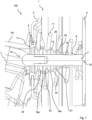
- a braking system 100 comprising a brake actuator 1 for a vehicle such as a commercial vehicle.
- the brake actuator 1 is connected to a brake mechanism 101 such as a disc brake.
- the brake actuator 1 comprises a housing 3 having a push rod aperture 5.
- the push rod aperture 5 preferably is a cylindrical cutout in the housing 3.
- the push rod aperture 5 is configured to accommodate a push rod 7 of the brake actuator 1.
- the push rod 7 comprises a proximal end 10 that is operatively coupled to a piston head 9 inside the housing 3. Opposite of the proximal end 10, the push rod 7 comprises a distal end 12 that is configured to connect to the brake mechanism 101.
- the push rod 7 is configured to move back and forth between a retracted position, shown in Fig. 1 , and an extended position, shown in Fig. 2 . In doing so, the push rod 7 moves back and forth through the push rod aperture 5 and into the housing of the brake mechanism 101.
- a return spring 11 is interposed between the housing 3 and the piston head 9 and effective to urge the push rod 7 towards the retracted position shown in Fig. 1 .
- the air volume inside the housing 3 between the piston head 9 and the push rod aperture 5 varies depending on the stroke position of the push rod 7.
- the volume increases, while during the stroke operation of the push rod 7, the volume inside the housing between the push rod aperture 5 and the piston head 9 decreases.
- This change in volume may cause pressure variations inside the housing 3 which could drag air into the housing 3, in particular, during the retraction movement of the push rod 7.
- dirt and dust particles may be dragged into the housing 3 and deteriorate the operation of the brake actuator 1 over time, which is therefore undesired.
- a sealing boot 13 is mounted to the push rod aperture 5 such that a first end portion 15 sealingly engages the push rod 7 at an intermediate region 8 of the push rod 7, in between the proximal end 10 and the distal end 12. A second end portion 17 of the sealing boot 13 engages the push rod aperture 5.
- the sealing boot 13 is configured to resiliently deform when the push rod 7 moves between its retracted position towards its extended position and vice versa.
- the sealing boot In the state shown in Fig. 1 , the sealing boot is in a relaxed state which corresponds to the retracted position of the push rod 7.
- the sealing boot 13 In its relaxed state, the sealing boot 13 is either not subjected to any stress, or at least not subjected to such a level of stress that the sealing boot 13 would be stretched or compressed to its limit. It may be slightly stretched or slightly compressed while the push rod 7 is in its retracted position, and these states are still to be considered as the relaxed state within the terms of this invention.
- the sealing boot comprises a plurality of outer folds, namely two first outer folds 19a, 19b, and a second outer fold 21.
- the first outer folds 19a, 19b are respectively joined by a set of first flanks 23 on each side of the fold, and the second outer fold 21 is joined by respective flanks 25 on each side thereof.
- the first flanks 23 are spread apart from one another, and the second flanks 25 are also spread apart from one another.
- Fig. 2 the same brake actuator 1 of Fig. 1 is shown in a second state of operation.
- the push rod 7 has been moved along its longitudinal direction L (cf. Fig. 1 ) into the extended position.
- the sealing boot 13 is now in a loaded state. In the loaded state, almost the entirety of the sealing boot 13 is located near the second end portion 17.
- the first folds 19a, 19b are compressed and abut against each other such that the respective first flanks 23 are directly adjacent to one another. However, the first folds 19a, 19b remain on a first side 4 of the second end portion 17, inside the housing 3.
- the second fold on the contrary, has been everted and the corresponding portion of the sealing boot 13 has been turned inside out such that the second outer fold 21 extends past the push rod aperture 5 to a second side 6 of the second end portion 17, outside of the housing 3 and towards the brake mechanism 101.
- the first end portion 15 of the sealing boot remains in sealing contact with the push rod 7 through this movement.
- the novel sealing boot 13 requires minimal space inside the housing 3 of the brake actuator 1 such that the return spring 11 and the piston head 9 may be positioned very close to the push rod aperture 5. This means that an amount of dead volume inside the housing 3 in the extended position of the push rod 7 may be minimized by the specific configuration of the sealing boot 13, which will be shown in more detail in the following Figs. 3-4 .
- Fig. 3 shows the sealing boot 13 in more detail. From the first end portion 15 to the second end portion 17, the sealing boot has an overall length l o .
- the second end portion 17 which is effective to engage the housing aperture 5 has an outer diameter D o .
- Adjacent to the second end portion 17, the sealing boot 13 may be considered as being subdivided in a first, uneversible portion Pu, and a second, eversible portion P E .
- the plurality of first outer folds 19a, 19b are allocated in the uneversible portion Pu, while the at least one second outer fold 21 is allocated in the eversible portion P E .
- first outer folds 19a, 19b are spaced apart from one another at a distance l 1 and the second outer fold 21 is spaced apart from its nearest first outer fold 19b at a distance l 2 .
- the first outer fold 19a has an outer diameter D 11 which is smaller than the overall diameter D o at the second end portion 17.
- Outer fold 19b has an outer diameter D 12 which is smaller than the outer diameter D 11 of outer fold 19a.
- the second outer fold 21 has an outer diameter D 2 which is smaller than both outer diameters D 11 , D 12 of the first outer folds 19a, 19b.
- R 2 is at 0.57 or less.
- the first diameter-to-length ratio R 11 , R 12 decreases from fold 19a to fold 19b by 2% +/- 0.5%.
- the first diameter-to-length ratios R 11 , R 12 are greater than the second diameter-to-length ratio R 2 by 4% or more.
- the sealing boot 13 further comprises, at the second end portion 17, an inner stop shoulder 27 which is tapered towards the push rod 7 at an angle ⁇ with respect to the longitudinal direction L.
- ⁇ is in a range of 15° to 75°, preferably of 30° to 60° relative to the longitudinal direction L.
- the stop shoulder 27 comprises a contact surface 29 for the first outer folds to abut against.
- all first outer folds 19a, 19b shall be understood to abut against the stop shoulder 27. i.e. its contact surface 29, namely either directly or indirectly.
- the first outer folds 19a, 19b are at a second distance l' 1 which is significantly smaller than the first distance l 1 in the relaxed state shown in Fig. 3 .
- the eversible portion P e has been turned inside out (with exception to the first end portion 15 which sealingly engages the push rod 7) and most importantly the second fold 21 has been everted at least partially past the push rod aperture 5 towards the outside of the housing 3.
- the second flanks 25 are spread apart further from one another than in the relaxed state shown in Fig. 3 .
- the second fold 21 is, in its loaded state shown in Fig. 4 , at a second distance l' 2 to the nearest first outer fold 19b that is greater than the first distance l 2 than in the relaxed state shown in Fig. 3 .
- the eversion movement within the eversible portion P E is facilitated by the dimensioning of the second outer fold 21 as mentioned herein above.
- the radial space requirement, i.e. perpendicular to the longitudinal direction, of the eversible portion P E in the loaded state of the sealing boot 13 is also minimal as can be seen from Fig. 4 .
- the second flanks 25 are almost straightened in the longitudinal direction L (cf. Fig. 3 ), thus urging towards - and staying close to - the push rod 7.
- the sealing boot 13 hardly consumes any radial space inside the brake mechanism 101.
Landscapes
- Engineering & Computer Science (AREA)
- General Engineering & Computer Science (AREA)
- Mechanical Engineering (AREA)
- Transportation (AREA)
- Sealing Devices (AREA)
Abstract
Description
- The invention relates to a brake actuator for a vehicle, in particular for a commercial vehicle, comprising a housing having a push rod aperture, a push rod configured to connect to a brake mechanism, wherein the push rod is configured to move back and forth through the push rod aperture between a retracted position and an extended position, and a sealing boot extending along the push rod, being flexible in a longitudinal direction, having a first end portion sealingly engaging the push rod at an intermediate region of the push rod and a second end portion sealingly engaging the push rod aperture, the boot having a plurality of outer folds distributed along the longitudinal direction wherein the boot is configured to resiliently deform between a relaxed state and a loaded state, the relaxed state corresponding to the retracted position of the push rod and the loaded state corresponding to the extended position of the push rod.
- Brake actuators of the aforementioned type are generally known in the art. Brake actuators of these types are typically used to provide service brake function and/or emergency or parking brake functions to the brake mechanism of the vehicle by moving the push rod back and forth such as to control the brake mechanism.
- Typically, the push rod has a proximal end that is arranged inside the housing and connected to a piston head which is moved by pneumatic or hydraulic pressure, and a distal end protruding outside the housing through the push rod aperture. In order to function properly, the interior of the brake actuator must be kept free from dirt and any other particulate matter which might interfere with the piston movement. Therefore, the sealing boot closes off the push rod aperture and is interposed between the housing and the push rod by sealingly engaging the respective portions on the push rod and the housing. Typically, the sealing boot engages a correspondingly shaped groove or otherwise prepared portion of the push rod which is arranged between the proximal end and the distal end of the push rod.
- The outer folds on the boot are typically provided between the first and second end portions of the boot to facilitate the transition of the boot from its relaxed position to the loaded position. In the prior art, the relaxed position would usually correspond to a boot in an unstressed, unloaded state, or a slightly hyperextended boot, i.e. stretched beyond its unloaded state in the longitudinal direction. The loaded state would correspond to a partially or fully compressed boot. Generally, and also in terms of the invention, the relaxed state is defined by a first boot length which is greater than a second boot length, the second boot length being the axial length of the boot in the longitudinal direction when the push rod is in the extended position. The relaxed position of the boot is maintained when the push rod is in the retracted position, in turn.
- In order to prevent the sealing boot from impairing the stroke movement of the push rod, the boot needs to be able to deform sufficiently far in the longitudinal direction. In order to do so, the sealing boot needs to have a substantial outer diameter in the end portion which engages the push rod aperture. Also, the sealing boot consumes space within the housing of the brake actuator, which space cannot be used by internal components of the brake actuator such as the piston had or any return springs, if present. It was desired to improve existing sealing boot designs such as to reduce the space requirement of the sealing boot within the brake actuator. It was also desired to improve the sealing boot design to prevent an impaired connectivity between the brake actuator and the brake mechanism. Further, it was desired to improve previously known sealing boot designs to allow for higher longevity of the sealing boot.
- Accordingly, it was an object of the invention to overcome the deficiencies mentioned above as far as possible. In particular, it was an object of the invention to suggest an approved brake actuator in which the sealing boot consumes less space without sacrificing longevity of the sealing boot.
- The object of the invention is attained by suggesting a brake actuator according to
claim 1. In particular, the invention suggests that the first end portion of the boot comprises a stop shoulder arranged inside the housing, and the plurality of folds comprises at least one first outer fold configured to abut against the stop shoulder inside the housing when the push rod is in the extended position and at least one second outer fold configured to evert past the stop shoulder to the outside of the housing when the push rod is in the extended position. The abutment against the stop shoulder shall be understood to encompass both direct and indirect abutment. - The invention is based upon the realization that the space requirements for a sealing boot are comparatively high when one attempts to have the sealing boot remain completely inside the brake actuator housing such that no boot material extends outside of the push rod aperture in the extended position of the push rod. Similarly, the space consumption of a sealing boot is comparatively high when all of the outer folds are allowed to transition from the brake actuator housing towards the outside of the brake actuator housing, whereby they are everted inside out due to the movement of the push rod into the extended position. By suggesting that some of the outer folds, namely the first outer folds, are retained inside the brake actuator housing by interacting immediately or intermittently with the stop shoulder, while some other, but not all, outer folds, namely the one or more second folds, are allowed to evert past the stop shoulder to the outside of the housing, the space requirement inside the brake actuator housing can be drastically reduced. A significant portion of the sealing boot material is allowed to exist the brake actuator housing, freeing up additional space inside the brake actuator housing for various optimization concepts. However, since only a portion of the outer folds are allowed to evert past the stop shoulder, the amount of sealing boot material that is moved outside of the brake actuator housing (therewith into or close to the brake mechanism) is also capped, leading to a reduced risk of interference with the brake mechanism. Also, it has been found that by distinguishing the movement capabilities of the first and second outer folds from one another, the opening diameter of the push rod aperture which holds the respective end portion of the sealing boot can be made smaller, thus improving the mechanical integrity of the brake actuator housing.
- In a preferred embodiment, the boot comprises a plurality of first outer folds, wherein the first outer folds are spaced apart from each other at a first distance when the boot is in the relaxed state, and at a second distance smaller than the first distance when the boot is in the loaded state. Preferably, the first outer folds adjoin when the boot is in the loaded state. After a first one of the first outer folds abuts against the stop shoulder, it essentially becomes the stop shoulder for the next adjacent first outer fold and so on.
- In a further preferred embodiment, the first outer folds are joined by first flanks, said flanks being configured to spread apart when the boot is in the relaxed state and to abut against one another when the boot is in the loaded state. On the radial inner end, the flanks may optionally transition seamlessly into one another, or may be joined by inner folds which allow for a more articulate movement of the flanks relative to one another.
- This, however, is a design choice depending on different variables such as the stroke length, material election and so forth.
- In a further preferred embodiment, the number of second outer folds is smaller than the number of first outer folds. Preferably, the number of second outer folds is one or two. The number of first outer folds preferably is two or more.
- In a further preferred embodiment, wherein the sealing boot has exactly one second outer fold, the second outer fold is axially spaced apart from the nearest first outer fold at a first distance when the boot is in the relaxed state, and at a second distance larger than the first distance when the boot is in the loaded state. Contrary to the movement of the first folds amongst one each other, the second fold, due to it being everted outside, is allowed to travel further away from the set of first folds along with the push rod. By being everted, the second fold elastically urges towards the push rod, helping the sealing boot on the whole keeping a small radial envelope outside of the brake actuator.
- In a further preferred embodiment, the at least one second outer fold is arranged adjacent the first end portion of the push rod, and the at least one first outer fold is arranged between the at least one second outer fold and second end portion of the push rod.
- In a further preferred embodiment, the at least one second outer fold is joined by second flanks, said second flanks being arranged completely inside the housing when the push rod is in the retracted position, and everted so as to extend at least partially outside the actuator housing when the push rod is in the extended position.
- In a further preferred embodiment, the stop shoulder extends circumferentially on the inside of the boot at the second end portion and comprises a contact surface for a first one of the first flanks, said first contact surface being tapered towards the longitudinal axis. It has been found that by tapering the contact surface towards the longitudinal axis, the space requirement for the first flanks and thus for a majority of the sealing boot can be minimized even further. Also, it facilitates the eversion of the at least one second outer fold under continued push rod movement.
- In a further preferred embodiment, the tapering angle of the contact surface is in a range of 15° to 75°, preferably in a range of 30° to 60°, relative to the longitudinal direction. The aforementioned ranges define the sweet spot which provides the best compromise between minimizing the space requirement of the sealing boot on the hand side at facilitating the movement of the at least one second outer fold when the push rod moves back and forth between the retracted position and the extended position.
- In a further preferred embodiment, in the relaxed state of the boot, the boot has a length in the longitudinal direction, the at least one first outer fold has an outer diameter, the at least one second outer fold has an outer diameter, the at least one first outer fold comprises a first diameter-to-length-ratio, and the at least one second outer fold comprises a second diameter-to-length-ratio, wherein the first diameter-to-length-ratio is greater than the second diameter-to-length-ratio. Herein, the respective ratio is equal to the respective outer diameter divided by the length of the boot in the longitudinal direction.
- Preferably, in embodiments where the sealing boot comprises a plurality of first outer folds, each first outer fold comprises a first diameter-to-length-ratio that is greater than the second diameter-to-length-ratio of the second outer folds.
- In a further preferred embodiment, the first diameter-to-length-ratio is in a range of 0,60 or greater. Additionally or alternatively, the second diameter-to-length-ratio is in a range of 0,57 or less.
- In a further preferred embodiment, when starting from the second end portion of the boot, the first diameter-to-length-ratio decreases from fold to fold by 2 % +/- 0,5 %. It has been found that by staggering the ratio from fold to fold as mentioned before, the space requirement of the sealing boot in the loaded state is minimized even further. When the second diameter-to-length-ratio is smaller than the first ratio as defined hereinabove, the version of the second fold or folds outwards is improved even further.
- In a further preferred embodiment, the first diameter-to-length-ratio, i.e. the smallest one of the first diameter-to-length-ratios in embodiments having more than one first outer fold, and different outside diameters of the outer folds, is greater than the second diameter-to-length-ratio by 4 % or more, preferably by 6 % or more.
- The invention has hereinabove been described with respect to the brake actuator itself in a first aspect.
- In a second aspect, the invention also relates to a sealing boot for a brake actuator, in particular for a brake actuator of a commercial vehicle, preferably for a brake actuator according to any one of the preferred embodiments described hereinabove. The boot is configured to extend along a push rod of the brake actuator and is flexible in a longitudinal direction, and comprises a first end portion configured to sealingly engage a push rod of the brake actuator at an intermediate region of the push rod, and a second end portion configured to sealingly engage a push rod aperture of a housing of the brake actuator, the boot having a plurality of outer folds distributed along the longitudinal direction, wherein the boot is configured to resiliently deform between a relaxed state and a loaded state, the relaxed state corresponding to a retracted position of the push rod and the loaded state corresponded to an extended position of the push rod.
- The invention attains the object mentioned initially in the second aspect by suggesting that the first end portion of the boot comprises a stop shoulder arranged inside the housing, and the plurality of outer folds comprises at least one first outer fold configured to abut against the stop shoulder on a first side of the second end portion when the boot is in the relaxed state, and at least one second outer fold configured to evert past the stop shoulder to a second side of the second end portion when the boot is in the loaded state.
- Insofar, the second aspect makes uses of the same advantages and claims the same benefits as the brake actuator of the first aspect. Preferred embodiments of the brake actuator of the first aspect are at the same time also preferred embodiments of the sealing boot of the second aspect and vice versa. Therefore, reference is made to the description of the first aspect hereinabove to avoid unnecessary repetition.
- Hereinafter, the invention will be described in more detail with reference to the accompanying drawings of a preferred embodiment. Herein:
- Fig. 1
- shows a schematic cross-sectional view of a braking system according to a preferred embodiment,
- Fig. 2
- shows the cross-sectional view of
Fig. 1 in an alternate state of operation, - Fig. 3
- shows a close-up cross-sectional view of a sealing boot of the braking system of
Figs. 1 and2 , and - Fig. 4
- shows the cross-sectional view of the sealing boot of
Fig. 1 in an alternate state of operation. - In
Fig. 1 , abraking system 100 is depicted comprising abrake actuator 1 for a vehicle such as a commercial vehicle. Thebrake actuator 1 is connected to abrake mechanism 101 such as a disc brake. - The
brake actuator 1 comprises ahousing 3 having apush rod aperture 5. Thepush rod aperture 5 preferably is a cylindrical cutout in thehousing 3. Thepush rod aperture 5 is configured to accommodate apush rod 7 of thebrake actuator 1. Thepush rod 7 comprises aproximal end 10 that is operatively coupled to apiston head 9 inside thehousing 3. Opposite of theproximal end 10, thepush rod 7 comprises adistal end 12 that is configured to connect to thebrake mechanism 101. Thepush rod 7 is configured to move back and forth between a retracted position, shown inFig. 1 , and an extended position, shown inFig. 2 . In doing so, thepush rod 7 moves back and forth through thepush rod aperture 5 and into the housing of thebrake mechanism 101. Areturn spring 11 is interposed between thehousing 3 and thepiston head 9 and effective to urge thepush rod 7 towards the retracted position shown inFig. 1 . - During movement of the
push rod 7, the air volume inside thehousing 3 between thepiston head 9 and thepush rod aperture 5 varies depending on the stroke position of thepush rod 7. During the return movement of the push rod towards the retracted position, the volume increases, while during the stroke operation of thepush rod 7, the volume inside the housing between thepush rod aperture 5 and thepiston head 9 decreases. This change in volume may cause pressure variations inside thehousing 3 which could drag air into thehousing 3, in particular, during the retraction movement of thepush rod 7. With the air, dirt and dust particles may be dragged into thehousing 3 and deteriorate the operation of thebrake actuator 1 over time, which is therefore undesired. - In order to prevent dust and dirt particles from entering into the
housing 3, a sealingboot 13 is mounted to thepush rod aperture 5 such that afirst end portion 15 sealingly engages thepush rod 7 at anintermediate region 8 of thepush rod 7, in between theproximal end 10 and thedistal end 12. Asecond end portion 17 of the sealingboot 13 engages thepush rod aperture 5. - The sealing
boot 13 is configured to resiliently deform when thepush rod 7 moves between its retracted position towards its extended position and vice versa. In the state shown inFig. 1 , the sealing boot is in a relaxed state which corresponds to the retracted position of thepush rod 7. In its relaxed state, the sealingboot 13 is either not subjected to any stress, or at least not subjected to such a level of stress that the sealingboot 13 would be stretched or compressed to its limit. It may be slightly stretched or slightly compressed while thepush rod 7 is in its retracted position, and these states are still to be considered as the relaxed state within the terms of this invention. - The sealing boot comprises a plurality of outer folds, namely two first
outer folds outer fold 21. The firstouter folds first flanks 23 on each side of the fold, and the secondouter fold 21 is joined byrespective flanks 25 on each side thereof. In the relaxed state of the sealing boot, shown inFig. 1 , thefirst flanks 23 are spread apart from one another, and thesecond flanks 25 are also spread apart from one another. - In
Fig. 2 , thesame brake actuator 1 ofFig. 1 is shown in a second state of operation. In this state of operation, thepush rod 7 has been moved along its longitudinal direction L (cf.Fig. 1 ) into the extended position. The sealingboot 13 is now in a loaded state. In the loaded state, almost the entirety of the sealingboot 13 is located near thesecond end portion 17. Thefirst folds first flanks 23 are directly adjacent to one another. However, thefirst folds first side 4 of thesecond end portion 17, inside thehousing 3. - The second fold, on the contrary, has been everted and the corresponding portion of the sealing
boot 13 has been turned inside out such that the secondouter fold 21 extends past thepush rod aperture 5 to asecond side 6 of thesecond end portion 17, outside of thehousing 3 and towards thebrake mechanism 101. Thefirst end portion 15 of the sealing boot remains in sealing contact with thepush rod 7 through this movement. - As can be seen from
Fig. 2 , in the loaded state, thenovel sealing boot 13 requires minimal space inside thehousing 3 of thebrake actuator 1 such that thereturn spring 11 and thepiston head 9 may be positioned very close to thepush rod aperture 5. This means that an amount of dead volume inside thehousing 3 in the extended position of thepush rod 7 may be minimized by the specific configuration of the sealingboot 13, which will be shown in more detail in the followingFigs. 3-4 . -
Fig. 3 shows the sealingboot 13 in more detail. From thefirst end portion 15 to thesecond end portion 17, the sealing boot has an overall length lo. Thesecond end portion 17 which is effective to engage thehousing aperture 5 has an outer diameter Do. Adjacent to thesecond end portion 17, the sealingboot 13 may be considered as being subdivided in a first, uneversible portion Pu, and a second, eversible portion PE. The plurality of firstouter folds outer fold 21 is allocated in the eversible portion PE. - In the state shown in
Fig. 3 , the firstouter folds outer fold 21 is spaced apart from its nearest firstouter fold 19b at a distance l2. - The first
outer fold 19a has an outer diameter D11 which is smaller than the overall diameter Do at thesecond end portion 17.Outer fold 19b has an outer diameter D12 which is smaller than the outer diameter D11 ofouter fold 19a. - The second
outer fold 21 has an outer diameter D2 which is smaller than both outer diameters D11, D12 of the firstouter folds - The first
outer fold 19a has a diameter-to-length ratio R11, wherein R11=D11/lo. - The second first
outer fold 19b has a diameter-to-length ratio R12, wherein R12=D12/lo. Both R11 and R12 are at 0.60 or greater, wherein preferably, R11 is greater than R12. - The second
outer fold 21 has a second diameter-to-length ratio R2, wherein R2=D2/lo. Preferably, R2 is at 0.57 or less. In preferred embodiments, as described further herein above, the first diameter-to-length ratio R11, R12 decreases fromfold 19a to fold 19b by 2% +/- 0.5%. - Further preferably, the first diameter-to-length ratios R11, R12 are greater than the second diameter-to-length ratio R2 by 4% or more.
- The sealing
boot 13 further comprises, at thesecond end portion 17, aninner stop shoulder 27 which is tapered towards thepush rod 7 at an angle α with respect to the longitudinal direction L. In preferred embodiments, α is in a range of 15° to 75°, preferably of 30° to 60° relative to the longitudinal direction L. - The
stop shoulder 27 comprises acontact surface 29 for the first outer folds to abut against. By abutting against thecontact surface 29 and then subsequently against each other, all firstouter folds stop shoulder 27. i.e. itscontact surface 29, namely either directly or indirectly. - When the sealing
boot 13 is transitioning from the relaxed state shown inFig. 3 to its loaded state shown inFig. 4 , the following changes occur:
By moving thepush rod 7 into the extended position, thefirst end portion 15 is forced past thepush rod aperture 5, and also past thesecond end portion 17 of the sealingboot 13 from itsfirst side 4 to itssecond side 6. The firstouter folds first flanks 23 contact each other. - As a consequence, in the loaded state shown in
Fig. 4 , the firstouter folds Fig. 3 . Contrary thereto, the eversible portion Pe has been turned inside out (with exception to thefirst end portion 15 which sealingly engages the push rod 7) and most importantly thesecond fold 21 has been everted at least partially past thepush rod aperture 5 towards the outside of thehousing 3. - The second flanks 25 are spread apart further from one another than in the relaxed state shown in
Fig. 3 . Thesecond fold 21 is, in its loaded state shown inFig. 4 , at a second distance l'2 to the nearest firstouter fold 19b that is greater than the first distance l2 than in the relaxed state shown inFig. 3 . - As is clear from
Fig. 4 , the longitudinal space requirement of the uneversible portion Pu of the sealingboot 13 inside thehousing 3 in its loaded state. Contributing factors for the minimal space requirement inside thehousing 3 is the tapering angle α of thestop shoulder 27 and the staggering of the outer diameters D11, D12 of the firstouter folds - At the same time, the eversion movement within the eversible portion PE is facilitated by the dimensioning of the second
outer fold 21 as mentioned herein above. The radial space requirement, i.e. perpendicular to the longitudinal direction, of the eversible portion PE in the loaded state of the sealingboot 13 is also minimal as can be seen fromFig. 4 . The second flanks 25 are almost straightened in the longitudinal direction L (cf.Fig. 3 ), thus urging towards - and staying close to - thepush rod 7. The sealingboot 13 hardly consumes any radial space inside thebrake mechanism 101. -
- 1
- brake actuator
- 3
- housing
- 4
- first side of sealing boot end portion
- 5
- push rod aperture
- 6
- second side of sealing boot end portion
- 7
- push rod
- 9
- piston head
- 11
- return spring
- 13
- sealing boot
- 15
- first end portion, sealing boot
- 17
- second end portion, sealing boot
- 19a, 19b
- first outer fold
- 21
- second outer fold
- 23
- first flank
- 25
- second flank
- 27
- stop shoulder
- 29
- contact surface
- 100
- braking system
- 101
- brake mechanism
- Do
- outer diameter, 2nd end portion
- D11, D12
- outer diameter, first outer fold
- D2
- outer diameter, second outer fold
- L
- longitudinal direction
- lo
- overall length
- l1
- first distance between first outer folds
- l1'
- second distance between first outer folds
- l2
- first distance between 1st, 2nd outer folds
- l2'
- distance
- Pu
- first, uneversible portion
- PE
- second, eversible portion
- R11, R12
- diameter-to-length ratio, first outer folds
- R2
- diameter-to-length ratio, second outer fold
- α
- angle
Claims (14)
- A brake actuator (1) for a vehicle, in particular for a commercial vehicle, comprising- a housing (3) having a push rod aperture (5),- a push rod (7) configured to connect to a brake mechanism (101); wherein the push rod (7) is configured to move back and forth through the push rod aperture (5) between a retracted position and an extended position; and- a sealing boot (13) extending along the push rod, being flexible in a longitudinal direction (L) and having a first end portion (15) sealingly engaging the push rod (7) at an intermediate region (8) of the push rod (7), and a second end portion (17) sealingly engaging the push-rod aperture (5); the boot (13) having a plurality of outer folds (19a, 19b, 21) distributed along the longitudinal direction (L); wherein the boot (13) is configured to resiliently deform between a relaxed state and a loaded state, the relaxed state corresponding to the retracted position of the push rod (7) and the loaded state corresponding to the extended position of the push rod (7);characterized in that
the first end portion (15) of the boot (13) comprises a stop shoulder (27) arranged inside the housing (3), and the plurality of outer folds (19a, 19b, 21) comprises- at least one first outer fold (19a, 19b) configured to abut against the stop shoulder (27) inside the housing (3) when the push rod (7) is in the extended position, and- at least one second outer fold (21) configured to evert past the stop shoulder (27) to the outside of the housing (3) when the push rod (7) is in the extended position. - The brake actuator (1) of claim 1,
characterized in that the boot (13) comprises a plurality of first outer folds (19a, 19b), wherein the first outer folds (19a, 19b) are spaced apart from each other at a first distance (l1) when the boot (13) is in the relaxed state; and at a second distance (l'1) smaller than the first distance (l1) when the boot (13) is in the loaded state, wherein preferably, the first outer folds (19a, 19b) adjoin when the boot (13) is in the loaded state. - The brake actuator (1) of claim 1 or 2,
wherein the first outer folds (19a, 19b) are joined by first flanks (23), said first flanks (23) being configured to spread apart when the boot (13) is in the relaxed state and to abut against one another when the boot (13) is in the loaded state. - The brake actuator (1) of any one of the preceding claims,
wherein the number of second outer folds (21) is smaller than the number of first outer folds (19a, 19b). - The brake actuator (1) of any one of the preceding claims,
having one second outer fold (21), wherein the second outer fold (21) is axially spaced apart from the nearest first outer fold (19b) at a first distance (l2) when the boot (13) is in the relaxed state; and at a second distance (l'2) larger than the first distance (l2) when the boot (13) is in the loaded state. - The brake actuator (1) of any one of the preceding claims,
characterized in that the at least one second outer fold (21) is arranged adjacent the first end portion (15) of the push rod (7); and the at least one first outer fold (19a, 19b) is arranged between the at least one second outer fold (21) and the second end portion (17) of the push rod (7). - The brake actuator (1) of any one of the preceding claims,
characterized in that the at least one second outer fold (21) is joined by second flanks (25), said second flanks (25) being arranged completely inside the housing (3) when the push rod (7) is in the retracted position, and everted so as to extend at least partially outside the actuator housing (3) when the push rod (7) is in the extended position. - The brake actuator (1) of any one of the preceding claims,
characterized in that the stop shoulder (27) extends circumferentially on the inside of the boot (13) at the second end portion (17) and comprises a contact surface (29) for a first one (19a) of the first flanks (19a, 19b), said contact surface (29) being tapered towards the push rod (7). - The brake actuator (1) of claim 8,
characterized in that the tapering angle (α) is in a range of 15° to 75°, preferably in a range of 30° to 60°, relative to the longitudinal direction (L). - The brake actuator (1) of any one of the preceding claims,
wherein in the relaxed state of the boot (13),- the boot (13) has a length (lo) in the longitidunal direction (L),- the at least one first outer fold has an outer diameter (D11, D12),- the at least one second outer fold has an outer diameter (D2),- the at least one first outer fold comprises a first diameter-to-length-ratio (R11, R12), and- the at least one second outer fold comprises a second diameter-to-length-ratio (R2), wherein the first diameter-to-length-ratio (R11, R12) is greater than the second diameter-to-length-ratio (R2), wherein the respective ratio (R11, R12, R2) is equal to the respective outer diameter (D11, D12, D2) divided by the length of the boot (13). - The brake actuator (1) of claim 10, wherein- the first diameter-to-length-ratio (R11, R12) is in a range of 0,60 or greater, and/or- the second diameter-to-length-ratio (R2) is in a range of 0,57 or less.
- The brake actuator (1) of claim 10 or 11,
wherein when starting from the second end portion (17) of the boot (13), the first diameter-to-length-ratio (R11, R12) decreases from fold to fold by 2% +/- 0,5%. - The brake actuator (1) of claim 12,
characterized in that the first diameter-to-length-ratio (R11, R12), i.e. the smallest one of the first diameter-to-length-ratios (R11, R12) is greater than the second diameter-to-length-ratio (R2) by 4% or more, preferably by 6% or more. - A sealing boot (13) for a brake actuator (1), in particular for a brake actuator (1) of a commercial vehicle, preferably for a brake actuator (1) of any one of the preceding claims,the boot (13) being configured to extend along a push rod (7) of the brake actuator (1) and being flexible in a longitudinal direction (L), and comprisinga first end portion (15) configured to sealingly engage the push rod (7) of the brake actuator (1) at an intermediate region (8) of the push rod (7), anda second end portion (17) configured to sealingly engage a push rod aperture (5) of a housing (3) of the brake actuator (1);the boot (13) having a plurality of outer folds (19a,19b,21) distributed along the longitudinal direction (L); wherein the boot (13) is configured to resiliently deform between a relaxed state and a loaded state, the relaxed state corresponding to a retracted position of the push rod (7) and the loaded state corresponding to an extended position of the push rod (7);characterized in thatthe first end portion (15) of the boot (13) comprises a stop shoulder (27) arranged inside the housing (3), and the plurality of outer folds (19a, 19b, 21) comprises- at least one first outer fold (19a, 19b) configured to abut against the stop shoulder (27) on a first side (4) of the second end portion (17) when the boot (13) is in the relaxed state, and- at least one second outer fold (21) configured to evert past the stop shoulder (27) to a second side of (6) the second end portion (17) when the boot (13) is in the loaded state.
Priority Applications (2)
| Application Number | Priority Date | Filing Date | Title |
|---|---|---|---|
| EP23170056.8A EP4454963B1 (en) | 2023-04-26 | 2023-04-26 | Brake actuator for a vehicle, and sealing boot therefore |
| PCT/EP2024/057478 WO2024223164A1 (en) | 2023-04-26 | 2024-03-20 | Brake actuator for a vehicle, and sealing boot therefore |
Applications Claiming Priority (1)
| Application Number | Priority Date | Filing Date | Title |
|---|---|---|---|
| EP23170056.8A EP4454963B1 (en) | 2023-04-26 | 2023-04-26 | Brake actuator for a vehicle, and sealing boot therefore |
Publications (2)
| Publication Number | Publication Date |
|---|---|
| EP4454963A1 true EP4454963A1 (en) | 2024-10-30 |
| EP4454963B1 EP4454963B1 (en) | 2025-09-10 |
Family
ID=86226459
Family Applications (1)
| Application Number | Title | Priority Date | Filing Date |
|---|---|---|---|
| EP23170056.8A Active EP4454963B1 (en) | 2023-04-26 | 2023-04-26 | Brake actuator for a vehicle, and sealing boot therefore |
Country Status (2)
| Country | Link |
|---|---|
| EP (1) | EP4454963B1 (en) |
| WO (1) | WO2024223164A1 (en) |
Citations (3)
| Publication number | Priority date | Publication date | Assignee | Title |
|---|---|---|---|---|
| EP0692651A1 (en) * | 1994-07-13 | 1996-01-17 | KNORR-BREMSE SYSTEME FÜR NUTZFAHRZEUGE GmbH | Disc brake cylinder, especially for utility vehicles |
| WO1999039082A1 (en) * | 1998-01-29 | 1999-08-05 | Indian Head Industries, Inc. | Brake actuator with tubular seal |
| EP2990683A1 (en) * | 2014-05-28 | 2016-03-02 | Indian Head Industries, Inc. | Electronic stroke sensor for air disc brake |
-
2023
- 2023-04-26 EP EP23170056.8A patent/EP4454963B1/en active Active
-
2024
- 2024-03-20 WO PCT/EP2024/057478 patent/WO2024223164A1/en not_active Ceased
Patent Citations (3)
| Publication number | Priority date | Publication date | Assignee | Title |
|---|---|---|---|---|
| EP0692651A1 (en) * | 1994-07-13 | 1996-01-17 | KNORR-BREMSE SYSTEME FÜR NUTZFAHRZEUGE GmbH | Disc brake cylinder, especially for utility vehicles |
| WO1999039082A1 (en) * | 1998-01-29 | 1999-08-05 | Indian Head Industries, Inc. | Brake actuator with tubular seal |
| EP2990683A1 (en) * | 2014-05-28 | 2016-03-02 | Indian Head Industries, Inc. | Electronic stroke sensor for air disc brake |
Also Published As
| Publication number | Publication date |
|---|---|
| WO2024223164A1 (en) | 2024-10-31 |
| EP4454963B1 (en) | 2025-09-10 |
Similar Documents
| Publication | Publication Date | Title |
|---|---|---|
| US20230150470A1 (en) | Spindle drive, actuator assembly, and method for producing a spindle drive | |
| EP2698297A2 (en) | Brake chamber, boot member, and bush member | |
| US6092637A (en) | Clutch with a sealing element, in particular an elastomer seal for use in annular cylinders such as in clutches | |
| EP4454963B1 (en) | Brake actuator for a vehicle, and sealing boot therefore | |
| CN102713329A (en) | Disc brake with reduced residual friction torque | |
| CN101839293B (en) | Parking mechanism of disc brakes | |
| JPH07293611A (en) | Collet type slack adjusting device and brake actuator | |
| CN112112912B (en) | Spring brake actuator and brake release mechanism for such a spring brake actuator | |
| US4608826A (en) | Master cylinder constructions | |
| EP4282722B1 (en) | Piston boot for a brake actuator, brake actuator comprising a respective piston boot and a disc brake | |
| US5647213A (en) | Master cylinder with quickfill stage | |
| CN101048307A (en) | Two-stage cylinder for automatic application and release of a hand brake of a railway vehicle | |
| JPH0431901B2 (en) | ||
| EP3953226B1 (en) | Spring brake, brake system, motor vehicle | |
| JP7797122B6 (en) | Hydraulic assembly pressure accumulator | |
| US20240262325A1 (en) | Pneumatic brake actuator and pushrod boot for such actuator | |
| EP1306562A1 (en) | Hydraulic actuator with retainer | |
| KR100936324B1 (en) | Clutch master cylinder | |
| US20160332613A1 (en) | Brake cylinder | |
| JP3843515B2 (en) | Hydraulic servo device for automatic transmission | |
| CN209309188U (en) | A kind of double sealing structure of disk brake | |
| EP4653274A1 (en) | Boot-seat-arrangement for a spring brake actuator for a pneumatic braking system for a vehicle, in particular utility vehicle, spring brake actuator, pneumatic braking system, and vehicle | |
| CN112392569B (en) | Engine brake actuating mechanism and engine auxiliary brake device | |
| CN207777480U (en) | Built-in zero drags hydraulic brake caliper | |
| CN120981671A (en) | Disengagement system for operating the clutch and clutch device |
Legal Events
| Date | Code | Title | Description |
|---|---|---|---|
| PUAI | Public reference made under article 153(3) epc to a published international application that has entered the european phase |
Free format text: ORIGINAL CODE: 0009012 |
|
| STAA | Information on the status of an ep patent application or granted ep patent |
Free format text: STATUS: THE APPLICATION HAS BEEN PUBLISHED |
|
| AK | Designated contracting states |
Kind code of ref document: A1 Designated state(s): AL AT BE BG CH CY CZ DE DK EE ES FI FR GB GR HR HU IE IS IT LI LT LU LV MC ME MK MT NL NO PL PT RO RS SE SI SK SM TR |
|
| STAA | Information on the status of an ep patent application or granted ep patent |
Free format text: STATUS: REQUEST FOR EXAMINATION WAS MADE |
|
| 17P | Request for examination filed |
Effective date: 20241111 |
|
| RBV | Designated contracting states (corrected) |
Designated state(s): AL AT BE BG CH CY CZ DE DK EE ES FI FR GB GR HR HU IE IS IT LI LT LU LV MC ME MK MT NL NO PL PT RO RS SE SI SK SM TR |
|
| GRAP | Despatch of communication of intention to grant a patent |
Free format text: ORIGINAL CODE: EPIDOSNIGR1 |
|
| STAA | Information on the status of an ep patent application or granted ep patent |
Free format text: STATUS: GRANT OF PATENT IS INTENDED |
|
| RIC1 | Information provided on ipc code assigned before grant |
Ipc: F16J 15/52 20060101ALI20250515BHEP Ipc: F16J 3/04 20060101ALI20250515BHEP Ipc: B60T 17/08 20060101AFI20250515BHEP |
|
| INTG | Intention to grant announced |
Effective date: 20250616 |
|
| GRAS | Grant fee paid |
Free format text: ORIGINAL CODE: EPIDOSNIGR3 |
|
| GRAA | (expected) grant |
Free format text: ORIGINAL CODE: 0009210 |
|
| STAA | Information on the status of an ep patent application or granted ep patent |
Free format text: STATUS: THE PATENT HAS BEEN GRANTED |
|
| AK | Designated contracting states |
Kind code of ref document: B1 Designated state(s): AL AT BE BG CH CY CZ DE DK EE ES FI FR GB GR HR HU IE IS IT LI LT LU LV MC ME MK MT NL NO PL PT RO RS SE SI SK SM TR |
|
| REG | Reference to a national code |
Ref country code: GB Ref legal event code: FG4D |
|
| REG | Reference to a national code |
Ref country code: CH Ref legal event code: EP |
|
| REG | Reference to a national code |
Ref country code: DE Ref legal event code: R096 Ref document number: 602023006478 Country of ref document: DE |
|
| REG | Reference to a national code |
Ref country code: IE Ref legal event code: FG4D |
|
| PG25 | Lapsed in a contracting state [announced via postgrant information from national office to epo] |
Ref country code: NO Free format text: LAPSE BECAUSE OF FAILURE TO SUBMIT A TRANSLATION OF THE DESCRIPTION OR TO PAY THE FEE WITHIN THE PRESCRIBED TIME-LIMIT Effective date: 20251210 |
|
| REG | Reference to a national code |
Ref country code: LT Ref legal event code: MG9D |
|
| PG25 | Lapsed in a contracting state [announced via postgrant information from national office to epo] |
Ref country code: FI Free format text: LAPSE BECAUSE OF FAILURE TO SUBMIT A TRANSLATION OF THE DESCRIPTION OR TO PAY THE FEE WITHIN THE PRESCRIBED TIME-LIMIT Effective date: 20250910 |
|
| REG | Reference to a national code |
Ref country code: NL Ref legal event code: MP Effective date: 20250910 |
|
| PG25 | Lapsed in a contracting state [announced via postgrant information from national office to epo] |
Ref country code: HR Free format text: LAPSE BECAUSE OF FAILURE TO SUBMIT A TRANSLATION OF THE DESCRIPTION OR TO PAY THE FEE WITHIN THE PRESCRIBED TIME-LIMIT Effective date: 20250910 |
|
| PG25 | Lapsed in a contracting state [announced via postgrant information from national office to epo] |
Ref country code: GR Free format text: LAPSE BECAUSE OF FAILURE TO SUBMIT A TRANSLATION OF THE DESCRIPTION OR TO PAY THE FEE WITHIN THE PRESCRIBED TIME-LIMIT Effective date: 20251211 |
|
| PG25 | Lapsed in a contracting state [announced via postgrant information from national office to epo] |
Ref country code: SE Free format text: LAPSE BECAUSE OF FAILURE TO SUBMIT A TRANSLATION OF THE DESCRIPTION OR TO PAY THE FEE WITHIN THE PRESCRIBED TIME-LIMIT Effective date: 20250910 |
|
| PG25 | Lapsed in a contracting state [announced via postgrant information from national office to epo] |
Ref country code: LV Free format text: LAPSE BECAUSE OF FAILURE TO SUBMIT A TRANSLATION OF THE DESCRIPTION OR TO PAY THE FEE WITHIN THE PRESCRIBED TIME-LIMIT Effective date: 20250910 |
|
| PG25 | Lapsed in a contracting state [announced via postgrant information from national office to epo] |
Ref country code: BG Free format text: LAPSE BECAUSE OF FAILURE TO SUBMIT A TRANSLATION OF THE DESCRIPTION OR TO PAY THE FEE WITHIN THE PRESCRIBED TIME-LIMIT Effective date: 20250910 Ref country code: PL Free format text: LAPSE BECAUSE OF FAILURE TO SUBMIT A TRANSLATION OF THE DESCRIPTION OR TO PAY THE FEE WITHIN THE PRESCRIBED TIME-LIMIT Effective date: 20250910 |
|
| PG25 | Lapsed in a contracting state [announced via postgrant information from national office to epo] |
Ref country code: RS Free format text: LAPSE BECAUSE OF FAILURE TO SUBMIT A TRANSLATION OF THE DESCRIPTION OR TO PAY THE FEE WITHIN THE PRESCRIBED TIME-LIMIT Effective date: 20251210 |
|
| PG25 | Lapsed in a contracting state [announced via postgrant information from national office to epo] |
Ref country code: ES Free format text: LAPSE BECAUSE OF FAILURE TO SUBMIT A TRANSLATION OF THE DESCRIPTION OR TO PAY THE FEE WITHIN THE PRESCRIBED TIME-LIMIT Effective date: 20250910 |
|
| REG | Reference to a national code |
Ref country code: AT Ref legal event code: MK05 Ref document number: 1835601 Country of ref document: AT Kind code of ref document: T Effective date: 20250910 |
|
| PG25 | Lapsed in a contracting state [announced via postgrant information from national office to epo] |
Ref country code: NL Free format text: LAPSE BECAUSE OF FAILURE TO SUBMIT A TRANSLATION OF THE DESCRIPTION OR TO PAY THE FEE WITHIN THE PRESCRIBED TIME-LIMIT Effective date: 20250910 |
|
| PG25 | Lapsed in a contracting state [announced via postgrant information from national office to epo] |
Ref country code: SM Free format text: LAPSE BECAUSE OF FAILURE TO SUBMIT A TRANSLATION OF THE DESCRIPTION OR TO PAY THE FEE WITHIN THE PRESCRIBED TIME-LIMIT Effective date: 20250910 |
|
| PG25 | Lapsed in a contracting state [announced via postgrant information from national office to epo] |
Ref country code: AT Free format text: LAPSE BECAUSE OF FAILURE TO SUBMIT A TRANSLATION OF THE DESCRIPTION OR TO PAY THE FEE WITHIN THE PRESCRIBED TIME-LIMIT Effective date: 20250910 |
|
| PG25 | Lapsed in a contracting state [announced via postgrant information from national office to epo] |
Ref country code: IT Free format text: LAPSE BECAUSE OF FAILURE TO SUBMIT A TRANSLATION OF THE DESCRIPTION OR TO PAY THE FEE WITHIN THE PRESCRIBED TIME-LIMIT Effective date: 20250910 |
|
| PG25 | Lapsed in a contracting state [announced via postgrant information from national office to epo] |
Ref country code: IS Free format text: LAPSE BECAUSE OF FAILURE TO SUBMIT A TRANSLATION OF THE DESCRIPTION OR TO PAY THE FEE WITHIN THE PRESCRIBED TIME-LIMIT Effective date: 20260110 |
|
| PGFP | Annual fee paid to national office [announced via postgrant information from national office to epo] |
Ref country code: FR Payment date: 20260309 Year of fee payment: 4 |
|
| PG25 | Lapsed in a contracting state [announced via postgrant information from national office to epo] |
Ref country code: PT Free format text: LAPSE BECAUSE OF FAILURE TO SUBMIT A TRANSLATION OF THE DESCRIPTION OR TO PAY THE FEE WITHIN THE PRESCRIBED TIME-LIMIT Effective date: 20260112 Ref country code: CZ Free format text: LAPSE BECAUSE OF FAILURE TO SUBMIT A TRANSLATION OF THE DESCRIPTION OR TO PAY THE FEE WITHIN THE PRESCRIBED TIME-LIMIT Effective date: 20250910 |
|
| PG25 | Lapsed in a contracting state [announced via postgrant information from national office to epo] |
Ref country code: EE Free format text: LAPSE BECAUSE OF FAILURE TO SUBMIT A TRANSLATION OF THE DESCRIPTION OR TO PAY THE FEE WITHIN THE PRESCRIBED TIME-LIMIT Effective date: 20250910 Ref country code: SK Free format text: LAPSE BECAUSE OF FAILURE TO SUBMIT A TRANSLATION OF THE DESCRIPTION OR TO PAY THE FEE WITHIN THE PRESCRIBED TIME-LIMIT Effective date: 20250910 |
|
| REG | Reference to a national code |
Ref country code: DE Ref legal event code: R097 Ref document number: 602023006478 Country of ref document: DE |
|
| PG25 | Lapsed in a contracting state [announced via postgrant information from national office to epo] |
Ref country code: LT Free format text: LAPSE BECAUSE OF FAILURE TO SUBMIT A TRANSLATION OF THE DESCRIPTION OR TO PAY THE FEE WITHIN THE PRESCRIBED TIME-LIMIT Effective date: 20250910 |
|
| PG25 | Lapsed in a contracting state [announced via postgrant information from national office to epo] |
Ref country code: DK Free format text: LAPSE BECAUSE OF FAILURE TO SUBMIT A TRANSLATION OF THE DESCRIPTION OR TO PAY THE FEE WITHIN THE PRESCRIBED TIME-LIMIT Effective date: 20250910 |
|
| PGFP | Annual fee paid to national office [announced via postgrant information from national office to epo] |
Ref country code: DE Payment date: 20260305 Year of fee payment: 4 |
|
| PLBE | No opposition filed within time limit |
Free format text: ORIGINAL CODE: 0009261 |
|
| STAA | Information on the status of an ep patent application or granted ep patent |
Free format text: STATUS: NO OPPOSITION FILED WITHIN TIME LIMIT |
|
| REG | Reference to a national code |
Ref country code: CH Ref legal event code: L10 Free format text: ST27 STATUS EVENT CODE: U-0-0-L10-L00 (AS PROVIDED BY THE NATIONAL OFFICE) Effective date: 20260722 |