EP4454951A1 - Console box for vehicle and vehicle - Google Patents
Console box for vehicle and vehicle Download PDFInfo
- Publication number
- EP4454951A1 EP4454951A1 EP24163382.5A EP24163382A EP4454951A1 EP 4454951 A1 EP4454951 A1 EP 4454951A1 EP 24163382 A EP24163382 A EP 24163382A EP 4454951 A1 EP4454951 A1 EP 4454951A1
- Authority
- EP
- European Patent Office
- Prior art keywords
- plate
- bottom plate
- console box
- receiving cavity
- deflector plate
- Prior art date
- Legal status (The legal status is an assumption and is not a legal conclusion. Google has not performed a legal analysis and makes no representation as to the accuracy of the status listed.)
- Withdrawn
Links
Images


Classifications
-
- B—PERFORMING OPERATIONS; TRANSPORTING
- B60—VEHICLES IN GENERAL
- B60R—VEHICLES, VEHICLE FITTINGS, OR VEHICLE PARTS, NOT OTHERWISE PROVIDED FOR
- B60R7/00—Stowing or holding appliances inside vehicle primarily intended for personal property smaller than suit-cases, e.g. travelling articles, or maps
- B60R7/04—Stowing or holding appliances inside vehicle primarily intended for personal property smaller than suit-cases, e.g. travelling articles, or maps in driver or passenger space, e.g. using racks
- B60R7/043—Stowing or holding appliances inside vehicle primarily intended for personal property smaller than suit-cases, e.g. travelling articles, or maps in driver or passenger space, e.g. using racks mounted on or under a seat
-
- B—PERFORMING OPERATIONS; TRANSPORTING
- B60—VEHICLES IN GENERAL
- B60N—SEATS SPECIALLY ADAPTED FOR VEHICLES; VEHICLE PASSENGER ACCOMMODATION NOT OTHERWISE PROVIDED FOR
- B60N2/00—Seats specially adapted for vehicles; Arrangement or mounting of seats in vehicles
- B60N2/75—Arm-rests
- B60N2/79—Adaptations for additional use of the arm-rests
- B60N2/793—Adaptations for additional use of the arm-rests for use as storage compartments
-
- B—PERFORMING OPERATIONS; TRANSPORTING
- B60—VEHICLES IN GENERAL
- B60R—VEHICLES, VEHICLE FITTINGS, OR VEHICLE PARTS, NOT OTHERWISE PROVIDED FOR
- B60R16/00—Electric or fluid circuits specially adapted for vehicles and not otherwise provided for; Arrangement of elements of electric or fluid circuits specially adapted for vehicles and not otherwise provided for
- B60R16/08—Electric or fluid circuits specially adapted for vehicles and not otherwise provided for; Arrangement of elements of electric or fluid circuits specially adapted for vehicles and not otherwise provided for fluid
Definitions
- the present application relates to the technical field of vehicles, and in particular to a console box for a vehicle.
- the present application further relates to a vehicle having the same.
- a console box is arranged in the middle of the front seats and/or the rear seats of a vehicle to place articles such as beverage bottles.
- a rubber pad is laid on a bottom plate of the console box.
- multiple holes are constructed in the bottom plate of the console box.
- the beverage bottle placed in the console box may shake or even topple over, causing the liquid in the beverage bottle to spill out.
- the spilled liquid leaves the console box through the holes in the bottom plate.
- the patent document US10449897B2 discloses a cup holder for a vehicle.
- the cup holder disclosed therein includes a main body, a light guide lens and a mat.
- the main body is provided with an inwardly recessed cup cavity.
- the light guide lens is arranged on the bottom plate of the cup cavity, and the mat is arranged on the light guide lens.
- the bottom plate of the cup cavity and the light guide lens are both provided with through holes, and two through holes facing each other form a drainage gap. When liquid is spilled into the cup cavity, it leaves the cup cavity through the drainage gap.
- part of the liquid drained from the console box diffusely flows under surface tension along the surface of the bottom plate facing away from the rubber pad, and further drips onto the electronic components arranged below the console box, causing failure of the electronic components.
- a first aspect of the present application proposes a console box for a vehicle.
- the console box for a vehicle includes: a receiving cavity, the receiving cavity having a bottom plate that is provided with one or more through holes; and a deflector plate, the deflector plate surrounding the one or more through holes, and the deflector plate being configured to extend downwards from a lower surface of the bottom plate and away from the bottom plate of the receiving cavity.
- an end surface of the deflector plate facing away from the bottom plate is configured as an inclined surface.
- the end surface of the deflector plate facing away from the bottom plate is provided with at least one drip head pointing downwards.
- the deflector plate includes one or more ring plates, each of the ring plates being configured to surround at least one of the one or more through holes.
- the deflector plate includes an annular outer plate and an annular inner plate; the inner plate is located at an inner side of the outer plate and spaced apart from the outer plate; and the one or more through holes are located between the outer plate and the inner plate.
- an upper surface, opposite to the lower surface, of the bottom plate is provided with one or more blocking ribs each surrounding at least one of the one or more through holes; or the upper surface is provided with one blocking rib, whereby the one or more through holes are located on an inner side of the blocking rib.
- the console box for a vehicle further includes a pad arranged in the receiving cavity and placed on the upper surface of the bottom plate.
- the pad includes a mating surface in contact with the upper surface of the bottom plate; the mating surface is provided with one or more flexible connectors; each of the one or more connectors is paired with the corresponding through hole; and the each of the one or more connectors is directed through and connected to the corresponding through hole.
- each of the one or more connectors is provided with a flange; the deflector plate is spaced apart from an edge of the through hole, so that a connecting region surrounding the through hole is formed; and the respective connector is directed through the corresponding through hole, so that the flange is snapped onto the connecting region.
- a downward extension length of the deflector plate is greater than a downward extension length of the connector.
- a second aspect of the present application proposes a vehicle.
- the vehicle includes: a vehicle body in which at least one seat is provided; the console box for a vehicle according to the previous description, the console box being arranged to be adjacent to the at least one seat; and at least one electronic module which is arranged below the bottom plate of the receiving cavity and is away from the deflector plate.
- the bottom plate of the receiving cavity is provided with a through hole, and a deflector plate surrounding the through hole is provided on a lower surface of the bottom plate.
- the deflector plate extends downward.
- the liquid spilled into the receiving cavity flows out of the through hole under gravity and further flows downward along the deflector plate to leave the receiving cavity, so that the drained liquid does not flow back up to the bottom plate.
- the case that the liquid diffusely flows along the lower surface of the bottom plate to the region corresponding to the electronic components is avoided, and thus failure of the electronic components caused by liquid dripping onto the electronic components is avoided.
- the directional term “down” refers to a direction substantially pointing to the ground
- the directional term “up” refers to a direction substantially away from the ground.
- the "axial direction” of a cylindrical or tubular member refers to a direction substantially parallel to the central axis of such member; and the “lateral direction” of a cylindrical or tubular member refers to a direction substantially perpendicular to the axial direction.
- FIG. 1 schematically shows a vehicle 1 according to an embodiment of the present application.
- the vehicle 1 includes a vehicle body 10, a console box 2 for a vehicle (hereinafter referred to as storage compartment 2) and an electronic module 12.
- a seat 11 is provided in the vehicle body 10.
- the seat 11 may include two front seats 111 and multiple rear seats 112.
- the storage compartment 2 is arranged to be adjacent to the seat 11 (for example, the storage compartment 2 is arranged between the two front seats 111).
- the storage compartment 2 includes a receiving cavity 20 into which passengers may place articles such as beverage bottles as needed.
- the electronic module 12 is arranged below the receiving cavity 20.
- the electronic module 12 may, for example, include an electrical parking brake module, which is well known to those skilled in the art and will not be repeated here.
- the storage compartment 2 will be described below with reference to FIGS. 2 to 8 .
- the storage compartment 2 includes a receiving cavity 20 and a deflector plate 24.
- the receiving cavity 20 has a bottom plate 202 that is provided with one or more through holes 203.
- the deflector plate 24 surrounds the one or more through holes 203.
- the deflector plate 24 is configured to extend downwards from a lower surface 205 of the bottom plate 202 and away from the bottom plate 202 of the receiving cavity 20.
- the electronic module 12 is arranged below the bottom plate 202 and is away from the deflector plate 24.
- the electronic module 12 is arranged in an electronic module installation region 121 located below the bottom plate 202.
- the one or more through holes 203 are surrounded inside the deflector plate 24, while the electronic module 12 is located outside the deflector plate 24.
- liquid when liquid is accidentally spilled into the receiving cavity 20 (for example, a beverage bottle shakes or topples over so that the liquid is spilled into the receiving cavity 20), it flows onto an upper surface 204 of the bottom plate 202 and further flows out of the receiving cavity 20 through the through holes 203.
- the liquid drained from the receiving cavity 20 further flows downward under gravity along the deflector plate 24 to leave the bottom plate 202 (or the receiving cavity 20), and does not flow back up to the lower surface 205 of the bottom plate 202.
- the liquid does not diffusely flow along the lower surface 205 of the bottom plate 202 to the region corresponding to the electronic component 12, so that failure of the electronic component 12 caused by liquid dripping onto the electronic component 12 is avoided.
- the console box further includes a pad 22.
- the pad 22 is arranged in the receiving cavity 20 and placed on the upper surface 204 of the bottom plate 202 that is opposite to the lower surface 205. In this way, the pad 22 can reduce the impact on the articles in the receiving cavity 20, protect these articles, and also improve the user's use experience.
- part of the liquid flows to the space between the pad 22 and the upper surface 204 of the bottom plate 202, and then flows out of the receiving cavity 20 through the through holes 203.
- the deflector plate 24 prevents the fluid from flowing back up to the lower surface 205 of the bottom plate 202, and thus the case that the liquid diffusely flows along the lower surface 205 of the bottom plate 202 to the region corresponding to the electronic component 12 is further avoided, so that failure of the electronic component 12 caused by liquid dripping onto the electronic component 12 is avoided.
- the pad 22 is made of flexible ethylene propylene diene monomer rubber (that is, EPDM rubber).
- EPDM rubber flexible ethylene propylene diene monomer rubber
- the pad 22 may also be made of other flexible materials, which will not be repeated here.
- the deflector plate 24 includes one or more ring plates each configured to surround one through hole 203.
- one deflector plate 24 is provided for each through hole 203.
- the bottom plate 202 is provided with six through holes 203.
- six deflector plates 24 are provided, and each deflector plate 24 surrounds one corresponding through hole 203. In such configuration, each deflector plate 24 only guides flow of the liquid from the through hole 203 itself surrounds.
- the deflector plate 24 is coaxial with the corresponding through hole 203.
- one deflector plate 24 may also surround two or more through holes 203. Thus, the deflector plate 24 is shared by those through holes 203.
- an end surface 241 of the deflector plate 24 facing away from the bottom plate 202 is configured as an inclined surface.
- the end surface 241 is at an angle to the axial direction A of the deflector plate 24.
- the inclined end surface 241 guides the liquid to quickly gather at the lowest point of the end surface 241 and then drip, so that the liquid quickly leaves the bottom plate 202, which further avoids the upward back flow of the liquid along the deflector plate 24.
- the first distance L1 between an inner edge 242 of the inclined end surface 241 and the lower surface 205 of the bottom plate 202 is greater than the second distance L2 between an outer edge 243 of the inclined end surface 241 and the lower surface 205 of the bottom plate 202 (that is, the inner edge 242 is lower than the outer edge 243).
- the liquid quickly gathers at the inner edge 242 of the end surface 241.
- the end surface 241 may also be configured into other shapes.
- the outer edge 243 is lower than the inner edge 242.
- the outer edge 243 may also be configured to have substantially the same length as the inner edge 242, but the middle portion of the end surface 241 protrudes downward beyond the outer edge 243 and the inner edge 242 (that is, the length of the middle portion of the end surface 241 is greater than the length of the outer edge 243 and the inner edge 242).
- the end surface 241 may also be configured as a plane as needed.
- the end surface 241 of the deflector plate 24 is provided with at least one drip head 244 pointing downwards.
- the drip head 244 is configured as a protrusion protruding downward from the end surface 241. With such configuration, the drip head 244 guides the droplets to drop in a predetermined direction, which prevents the droplets from randomly splashing and thereby prevents the droplets from splashing onto the electronic module 12 or other components.
- the deflector plate 24 includes an annular outer plate 245 and an annular inner plate 246.
- the inner plate 246 is located radially inside the outer plate 245 and spaced radially from the outer plate 245.
- the one or more through holes 203 are located between the outer plate 245 and the inner plate 246.
- the outer plate 245 and the inner plate 246 both serve to guide flow of the liquid.
- the outer plate 245 and the inner plate 246 may be shared by these through holes 203, so that there is no need to provide a separate deflector plate for each through hole 203, simplifying the manufacturing of the storage compartment 2.
- the end surfaces of the outer plate 245 and/or the inner plate 246 may be configured into the inclined surface as previously described, and may be further provided with the drip head as previously described, which will not be repeated here.
- the length of the deflector plate 24 is between 4 mm and 7 mm.
- the deflector plate 24 of such length is sufficient to guide the liquid to flow away from the receiving cavity 20, and the liquid does not flow back onto the bottom plate 202.
- such deflector plate 24 is relatively short and occupies a small space, which facilitates the assembly of the storage compartment 2 in the vehicle body 10. It should be understood that, in the case that the deflector plate 24 includes the inner plate 246 and the outer plate 245, the inner plate 246 and the outer plate 245 each have an extension length ranging from 4 mm to 7 mm. Of course, those skilled in the art can also configure the deflector plate 24 into other length dimensions according to the actual needs.
- the deflector plate 24 is integrally formed with the bottom plate 202 of the receiving cavity 20, for example, by injection molding.
- the deflector plate 24 and the bottom plate 202 of the receiving cavity 20 may also be formed separately and then connected together.
- a blocking rib 206 surrounding the through hole 203 is provided on the upper surface 204 of the bottom plate 202.
- the blocking rib 206 protrudes from the upper surface 204, opposite to the lower surface 205, of the bottom plate 202 (in other words, the blocking rib 206 protrudes toward the pad 22).
- the blocking rib 206 blocks the liquid between the pad 22 and the upper surface 204 of the bottom plate 202 from flowing into the through hole 203, thereby reducing the liquid flowing out of the receiving cavity 20 through the through hole 203, which also prevents the liquid from dripping onto the electronic component 12 arranged below the bottom plate 202.
- the liquid flowing out of the receiving cavity 20 and entering the vehicle body 10 is reduced or even eliminated, which is particularly advantageous because the liquid entering the vehicle body 10 is difficult to clean. It should be understood that, in the case of providing the blocking rib 206, the passenger can timely clean the liquid spilled into the receiving cavity 20 to minimize the liquid flowing into the through hole 203.
- the protrusion dimension of the blocking rib 206 is between 0.3 mm and 0.5 mm. In this way, the protrusion dimension of the blocking rib 206 is small and does not affect the laying of the pad 22 on the bottom plate 202.
- the blocking rib 206 may surround only one through hole 203 (as shown in FIG. 6 ). In other embodiments, the blocking rib 206 may surround multiple through holes 203. In addition, it is also applicable to provide only one blocking rib 206 which surrounds the multiple through holes 203 (as shown in FIG. 9 ). Those are readily known to those skilled in the art and will not be described here.
- the pad 22 includes a mating surface 221 in contact with the upper surface 204 of the bottom plate 202. As shown in FIG. 8 , the mating surface 221 is provided with one or more flexible connectors 225. Each connector 225 is directed through and connected to the corresponding through hole 203. Thus, the pad 22 can be firmly mounted on the bottom plate 202.
- the bottom plate 202 is substantially rectangular, and three through holes 203 are arranged at intervals along each long edge of the bottom plate 202.
- the pad 22 is also substantially rectangular, and three connectors 225 are arranged at intervals along each long edge of the pad 22 (as shown in FIG. 8 ).
- those skilled in the art can also configure the bottom plate 202 into other shapes according to the actual situation, and provide other numbers of the through holes on the bottom plate 202. Consequently, the shape of the pad 22 and the number of the connectors 225 are changed accordingly.
- the mating surface 221 of the pad 22 is further provided with a pattern 223.
- the pattern 223 improves the friction between the pad 22 and the bottom plate 202, thereby further improving the firmness of the pad 22 on the bottom plate 202.
- each connector 225 is provided with a flange 226.
- the deflector plate 24 is spaced apart from an edge of the through hole 203, so that a connecting region 247 surrounding the through hole 203 is formed.
- the flange 226 is squeezed so as to pass through the through hole 203.
- the flange 226 automatically expands and snaps onto the connecting region 247 after it is directed through the through hole 203, thereby achieving a stable connection between the connector 225 and the through hole 203.
- the pad 22 is stably arranged on the bottom plate 202.
- the width of the connecting region 247 is between 3 mm and 5 mm.
- the connecting region 247 of such size ensures that the flange 226 can be stably snapped onto the connecting region 247.
- the overall lateral dimension of the deflector plate 24 is not too large with respect to the through hole 203, which facilitates the assembly of the storage compartment 2 in the vehicle body 10.
- a downward extension length of the deflector plate 24 is greater than a downward extension length of the connector 225.
- the connector 225 is located inside the deflector plate 24 along the axial direction of the connector 225, so that the deflector plate 24 protects the connector 225 from accidentally pushing the connector 225 out of the through hole 203. Further, since the connector 225 is located inside the deflector plate 24, the insertion of the connector 225 into the through hole 203 during the assembly of the pad 22 is not hindered by other components located at the lower surface 205 of the bottom plate 202, which facilitates the assembly of the pad 22.
- the downward extension length of the deflector plate 24 is 5 mm, and the downward extension length of the connector 225 is 3mm. It should be understood that the downward extension length of the deflector plate 24 may also be equal to or smaller than the downward extension length of the connector 225, depending on the actual situation.
Landscapes
- Engineering & Computer Science (AREA)
- Mechanical Engineering (AREA)
- Aviation & Aerospace Engineering (AREA)
- Transportation (AREA)
- Vehicle Step Arrangements And Article Storage (AREA)
Abstract
A console box for a vehicle including a receiving cavity (20), the receiving cavity (20) having a bottom plate (202) that is provided with one or more through holes (203); and a deflector plate (24), the deflector plate (24) surrounding the one or more through holes (203), and the deflector plate (24) being configured to extend downwards from a lower surface (205) of the bottom plate (202) and away from the bottom plate (202) of the receiving cavity (20). According to the console box for a vehicle of the present application, the liquid spilled into the receiving cavity (20) flows out of the through hole (203) under gravity and further flows downward along the deflector plate (24) to leave the receiving cavity (20), so that the drained liquid does not flow back up to the bottom plate (202). Thus, failure of electronic components caused by liquid dripping onto the electronic components which are arranged below the bottom plate (202) can be avoided.
Description
- The present application relates to the technical field of vehicles, and in particular to a console box for a vehicle. The present application further relates to a vehicle having the same.
- A console box is arranged in the middle of the front seats and/or the rear seats of a vehicle to place articles such as beverage bottles. In order to improve the user's use experience, a rubber pad is laid on a bottom plate of the console box. In addition, multiple holes are constructed in the bottom plate of the console box. During traveling of the vehicle, the beverage bottle placed in the console box may shake or even topple over, causing the liquid in the beverage bottle to spill out. The spilled liquid leaves the console box through the holes in the bottom plate. For example, the patent document
US10449897B2 - However, part of the liquid drained from the console box diffusely flows under surface tension along the surface of the bottom plate facing away from the rubber pad, and further drips onto the electronic components arranged below the console box, causing failure of the electronic components.
- Regarding the above technical problems, a first aspect of the present application proposes a console box for a vehicle. The console box for a vehicle includes: a receiving cavity, the receiving cavity having a bottom plate that is provided with one or more through holes; and a deflector plate, the deflector plate surrounding the one or more through holes, and the deflector plate being configured to extend downwards from a lower surface of the bottom plate and away from the bottom plate of the receiving cavity.
- In an embodiment, an end surface of the deflector plate facing away from the bottom plate is configured as an inclined surface.
- In an embodiment, the end surface of the deflector plate facing away from the bottom plate is provided with at least one drip head pointing downwards.
- In an embodiment, the deflector plate includes one or more ring plates, each of the ring plates being configured to surround at least one of the one or more through holes.
- In one embodiment, the deflector plate includes an annular outer plate and an annular inner plate; the inner plate is located at an inner side of the outer plate and spaced apart from the outer plate; and the one or more through holes are located between the outer plate and the inner plate.
- In an embodiment, an upper surface, opposite to the lower surface, of the bottom plate is provided with one or more blocking ribs each surrounding at least one of the one or more through holes; or the upper surface is provided with one blocking rib, whereby the one or more through holes are located on an inner side of the blocking rib.
- In an embodiment, the console box for a vehicle further includes a pad arranged in the receiving cavity and placed on the upper surface of the bottom plate.
- In an embodiment, the pad includes a mating surface in contact with the upper surface of the bottom plate; the mating surface is provided with one or more flexible connectors; each of the one or more connectors is paired with the corresponding through hole; and the each of the one or more connectors is directed through and connected to the corresponding through hole.
- In one embodiment, each of the one or more connectors is provided with a flange; the deflector plate is spaced apart from an edge of the through hole, so that a connecting region surrounding the through hole is formed; and the respective connector is directed through the corresponding through hole, so that the flange is snapped onto the connecting region.
- In an embodiment, a downward extension length of the deflector plate is greater than a downward extension length of the connector.
- A second aspect of the present application proposes a vehicle. The vehicle includes: a vehicle body in which at least one seat is provided; the console box for a vehicle according to the previous description, the console box being arranged to be adjacent to the at least one seat; and at least one electronic module which is arranged below the bottom plate of the receiving cavity and is away from the deflector plate.
- The beneficial effects of the present application are as follows. In the console box for a vehicle according to the present application, the bottom plate of the receiving cavity is provided with a through hole, and a deflector plate surrounding the through hole is provided on a lower surface of the bottom plate. The deflector plate extends downward. In this way, the liquid spilled into the receiving cavity flows out of the through hole under gravity and further flows downward along the deflector plate to leave the receiving cavity, so that the drained liquid does not flow back up to the bottom plate. Thus, the case that the liquid diffusely flows along the lower surface of the bottom plate to the region corresponding to the electronic components is avoided, and thus failure of the electronic components caused by liquid dripping onto the electronic components is avoided.
- The accompanying drawings described herein are used for providing a further understanding of the present application, and constitute a part of the present application. Exemplary embodiments of the present application and descriptions thereof are used for explaining the present application, and do not constitute any inappropriate limitation to the present application. In the drawings:
-
FIG. 1 schematically shows a vehicle according to an embodiment of the present application; -
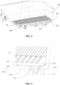
FIG. 2 schematically shows a console box for a vehicle according to an embodiment of the present application; -
FIG. 3 is a cross-sectional view of a portion of the console box; -
FIG. 4 schematically shows the positional relationship of a connector and a deflector plate; -
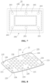
FIG. 5 schematically shows a lower surface of a bottom plate of a receiving cavity of the console box. -
FIG. 6 schematically shows a cross-sectional view of the deflector plate according to an embodiment, in which the positional relationship between a blocking rib and a through hole is shown; -
FIG. 7 schematically shows the deflector plate according to another embodiment; -
FIG. 8 schematically shows a mating surface of a pad; and -
FIG. 9 schematically shows the positional relationship between the blocking rib and the through hole according to another embodiment. - In order to make the objects, technical solutions, and advantages of the present application clearer, the technical solutions in the embodiments of the present application are described clearly and completely in conjunction with the specific embodiments and corresponding drawings of the present application hereinafter. It is apparent that the described embodiments are only some rather than all embodiments of the present application. Based on the embodiments of the present application, all other embodiments obtained by those of ordinary skill in the art without any creative work fall within the scope of protection of the present application.
- It should be understood that in the present application, the directional term "down" refers to a direction substantially pointing to the ground, and the directional term "up" refers to a direction substantially away from the ground. The "axial direction" of a cylindrical or tubular member refers to a direction substantially parallel to the central axis of such member; and the "lateral direction" of a cylindrical or tubular member refers to a direction substantially perpendicular to the axial direction.
-
FIG. 1 schematically shows a vehicle 1 according to an embodiment of the present application. As shown inFIG. 1 , the vehicle 1 includes avehicle body 10, aconsole box 2 for a vehicle (hereinafter referred to as storage compartment 2) and anelectronic module 12. Aseat 11 is provided in thevehicle body 10. For example, theseat 11 may include twofront seats 111 and multiplerear seats 112. Thestorage compartment 2 is arranged to be adjacent to the seat 11 (for example, thestorage compartment 2 is arranged between the two front seats 111). Thestorage compartment 2 includes a receivingcavity 20 into which passengers may place articles such as beverage bottles as needed. Theelectronic module 12 is arranged below thereceiving cavity 20. Theelectronic module 12 may, for example, include an electrical parking brake module, which is well known to those skilled in the art and will not be repeated here. - The
storage compartment 2 will be described below with reference toFIGS. 2 to 8 . - As shown in
FIGS. 2 and3 , thestorage compartment 2 includes areceiving cavity 20 and adeflector plate 24. Specifically, as shown inFIG. 4 , thereceiving cavity 20 has abottom plate 202 that is provided with one or more throughholes 203. As further shown inFIGS. 4 ,6 and7 , thedeflector plate 24 surrounds the one or more throughholes 203. As further shown inFIG. 5 , thedeflector plate 24 is configured to extend downwards from alower surface 205 of thebottom plate 202 and away from thebottom plate 202 of the receivingcavity 20. - The
electronic module 12 is arranged below thebottom plate 202 and is away from thedeflector plate 24. For example, as shown inFIG. 3 , theelectronic module 12 is arranged in an electronicmodule installation region 121 located below thebottom plate 202. In other words, the one or more throughholes 203 are surrounded inside thedeflector plate 24, while theelectronic module 12 is located outside thedeflector plate 24. - In accordance with the
storage compartment 2 of the present application, when liquid is accidentally spilled into the receiving cavity 20 (for example, a beverage bottle shakes or topples over so that the liquid is spilled into the receiving cavity 20), it flows onto anupper surface 204 of thebottom plate 202 and further flows out of the receivingcavity 20 through the throughholes 203. The liquid drained from the receivingcavity 20 further flows downward under gravity along thedeflector plate 24 to leave the bottom plate 202 (or the receiving cavity 20), and does not flow back up to thelower surface 205 of thebottom plate 202. Thus, the liquid does not diffusely flow along thelower surface 205 of thebottom plate 202 to the region corresponding to theelectronic component 12, so that failure of theelectronic component 12 caused by liquid dripping onto theelectronic component 12 is avoided. - In an embodiment, as shown in
FIGS. 2 and3 , the console box further includes apad 22. Thepad 22 is arranged in the receivingcavity 20 and placed on theupper surface 204 of thebottom plate 202 that is opposite to thelower surface 205. In this way, thepad 22 can reduce the impact on the articles in the receivingcavity 20, protect these articles, and also improve the user's use experience. In addition, when the liquid is accidentally spilled into the receivingcavity 20, part of the liquid flows to the space between thepad 22 and theupper surface 204 of thebottom plate 202, and then flows out of the receivingcavity 20 through the throughholes 203. In this case, as described above, thedeflector plate 24 prevents the fluid from flowing back up to thelower surface 205 of thebottom plate 202, and thus the case that the liquid diffusely flows along thelower surface 205 of thebottom plate 202 to the region corresponding to theelectronic component 12 is further avoided, so that failure of theelectronic component 12 caused by liquid dripping onto theelectronic component 12 is avoided. - In an embodiment, the
pad 22 is made of flexible ethylene propylene diene monomer rubber (that is, EPDM rubber). Of course, thepad 22 may also be made of other flexible materials, which will not be repeated here. - In an embodiment, as shown in
FIGS. 4 and5 , thedeflector plate 24 includes one or more ring plates each configured to surround one throughhole 203. In other words, onedeflector plate 24 is provided for each throughhole 203. For example, as shown inFIG. 5 , thebottom plate 202 is provided with six throughholes 203. Correspondingly, sixdeflector plates 24 are provided, and eachdeflector plate 24 surrounds one corresponding throughhole 203. In such configuration, eachdeflector plate 24 only guides flow of the liquid from the throughhole 203 itself surrounds. In an embodiment, thedeflector plate 24 is coaxial with the corresponding throughhole 203. In other embodiments, onedeflector plate 24 may also surround two or more throughholes 203. Thus, thedeflector plate 24 is shared by those throughholes 203. - Optionally, as shown in
FIG. 6 , anend surface 241 of thedeflector plate 24 facing away from thebottom plate 202 is configured as an inclined surface. In other words, theend surface 241 is at an angle to the axial direction A of thedeflector plate 24. Theinclined end surface 241 guides the liquid to quickly gather at the lowest point of theend surface 241 and then drip, so that the liquid quickly leaves thebottom plate 202, which further avoids the upward back flow of the liquid along thedeflector plate 24. - In a specific embodiment, as further shown in
FIG. 6 , the first distance L1 between aninner edge 242 of theinclined end surface 241 and thelower surface 205 of thebottom plate 202 is greater than the second distance L2 between anouter edge 243 of theinclined end surface 241 and thelower surface 205 of the bottom plate 202 (that is, theinner edge 242 is lower than the outer edge 243). In this way, the liquid quickly gathers at theinner edge 242 of theend surface 241. It should be understood that theend surface 241 may also be configured into other shapes. For example, theouter edge 243 is lower than theinner edge 242. Theouter edge 243 may also be configured to have substantially the same length as theinner edge 242, but the middle portion of theend surface 241 protrudes downward beyond theouter edge 243 and the inner edge 242 (that is, the length of the middle portion of theend surface 241 is greater than the length of theouter edge 243 and the inner edge 242). Of course, theend surface 241 may also be configured as a plane as needed. - Optionally, as further shown in
FIG. 6 , theend surface 241 of thedeflector plate 24 is provided with at least onedrip head 244 pointing downwards. In other words, thedrip head 244 is configured as a protrusion protruding downward from theend surface 241. With such configuration, thedrip head 244 guides the droplets to drop in a predetermined direction, which prevents the droplets from randomly splashing and thereby prevents the droplets from splashing onto theelectronic module 12 or other components. - In another embodiment, as shown in
FIG. 7 , thedeflector plate 24 includes an annularouter plate 245 and an annularinner plate 246. Theinner plate 246 is located radially inside theouter plate 245 and spaced radially from theouter plate 245. In this case, the one or more throughholes 203 are located between theouter plate 245 and theinner plate 246. With such configuration, theouter plate 245 and theinner plate 246 both serve to guide flow of the liquid. In the case that thebottom plate 202 is provided with multiple throughholes 203, theouter plate 245 and theinner plate 246 may be shared by these throughholes 203, so that there is no need to provide a separate deflector plate for each throughhole 203, simplifying the manufacturing of thestorage compartment 2. It should be understood that the end surfaces of theouter plate 245 and/or theinner plate 246 may be configured into the inclined surface as previously described, and may be further provided with the drip head as previously described, which will not be repeated here. - Optionally, the length of the
deflector plate 24 is between 4 mm and 7 mm. Thedeflector plate 24 of such length is sufficient to guide the liquid to flow away from the receivingcavity 20, and the liquid does not flow back onto thebottom plate 202. In addition,such deflector plate 24 is relatively short and occupies a small space, which facilitates the assembly of thestorage compartment 2 in thevehicle body 10. It should be understood that, in the case that thedeflector plate 24 includes theinner plate 246 and theouter plate 245, theinner plate 246 and theouter plate 245 each have an extension length ranging from 4 mm to 7 mm. Of course, those skilled in the art can also configure thedeflector plate 24 into other length dimensions according to the actual needs. - In an embodiment, the
deflector plate 24 is integrally formed with thebottom plate 202 of the receivingcavity 20, for example, by injection molding. Of course, thedeflector plate 24 and thebottom plate 202 of the receivingcavity 20 may also be formed separately and then connected together. - Optionally, as further shown in
FIG. 6 , a blockingrib 206 surrounding the throughhole 203 is provided on theupper surface 204 of thebottom plate 202. The blockingrib 206 protrudes from theupper surface 204, opposite to thelower surface 205, of the bottom plate 202 (in other words, the blockingrib 206 protrudes toward the pad 22). The blockingrib 206 blocks the liquid between thepad 22 and theupper surface 204 of thebottom plate 202 from flowing into the throughhole 203, thereby reducing the liquid flowing out of the receivingcavity 20 through the throughhole 203, which also prevents the liquid from dripping onto theelectronic component 12 arranged below thebottom plate 202. Furthermore, due to the blocking effect of the blockingrib 206, the liquid flowing out of the receivingcavity 20 and entering thevehicle body 10 is reduced or even eliminated, which is particularly advantageous because the liquid entering thevehicle body 10 is difficult to clean. It should be understood that, in the case of providing the blockingrib 206, the passenger can timely clean the liquid spilled into the receivingcavity 20 to minimize the liquid flowing into the throughhole 203. - In an embodiment, the protrusion dimension of the blocking
rib 206 is between 0.3 mm and 0.5 mm. In this way, the protrusion dimension of the blockingrib 206 is small and does not affect the laying of thepad 22 on thebottom plate 202. - In an embodiment, the blocking
rib 206 may surround only one through hole 203 (as shown inFIG. 6 ). In other embodiments, the blockingrib 206 may surround multiple throughholes 203. In addition, it is also applicable to provide only one blockingrib 206 which surrounds the multiple through holes 203 (as shown inFIG. 9 ). Those are readily known to those skilled in the art and will not be described here. - Optionally, the
pad 22 includes amating surface 221 in contact with theupper surface 204 of thebottom plate 202. As shown inFIG. 8 , themating surface 221 is provided with one or moreflexible connectors 225. Eachconnector 225 is directed through and connected to the corresponding throughhole 203. Thus, thepad 22 can be firmly mounted on thebottom plate 202. - In an embodiment, as shown in
FIG. 5 , thebottom plate 202 is substantially rectangular, and three throughholes 203 are arranged at intervals along each long edge of thebottom plate 202. Correspondingly, thepad 22 is also substantially rectangular, and threeconnectors 225 are arranged at intervals along each long edge of the pad 22 (as shown inFIG. 8 ). Of course, those skilled in the art can also configure thebottom plate 202 into other shapes according to the actual situation, and provide other numbers of the through holes on thebottom plate 202. Consequently, the shape of thepad 22 and the number of theconnectors 225 are changed accordingly. - In an embodiment, as further shown in
FIG. 8 , themating surface 221 of thepad 22 is further provided with apattern 223. Thepattern 223 improves the friction between thepad 22 and thebottom plate 202, thereby further improving the firmness of thepad 22 on thebottom plate 202. - Optionally, as shown in
FIG. 6 , eachconnector 225 is provided with aflange 226. Thedeflector plate 24 is spaced apart from an edge of the throughhole 203, so that a connectingregion 247 surrounding the throughhole 203 is formed. Thus, when theconnector 225 is directed through the throughhole 203, theflange 226 is squeezed so as to pass through the throughhole 203. Theflange 226 automatically expands and snaps onto the connectingregion 247 after it is directed through the throughhole 203, thereby achieving a stable connection between theconnector 225 and the throughhole 203. Thus, thepad 22 is stably arranged on thebottom plate 202. - In an embodiment, the width of the connecting
region 247 is between 3 mm and 5 mm. The connectingregion 247 of such size ensures that theflange 226 can be stably snapped onto the connectingregion 247. Furthermore, the overall lateral dimension of thedeflector plate 24 is not too large with respect to the throughhole 203, which facilitates the assembly of thestorage compartment 2 in thevehicle body 10. - Optionally, as shown in
FIGS. 4 and6 , a downward extension length of thedeflector plate 24 is greater than a downward extension length of theconnector 225. Overall, theconnector 225 is located inside thedeflector plate 24 along the axial direction of theconnector 225, so that thedeflector plate 24 protects theconnector 225 from accidentally pushing theconnector 225 out of the throughhole 203. Further, since theconnector 225 is located inside thedeflector plate 24, the insertion of theconnector 225 into the throughhole 203 during the assembly of thepad 22 is not hindered by other components located at thelower surface 205 of thebottom plate 202, which facilitates the assembly of thepad 22. In an embodiment, the downward extension length of thedeflector plate 24 is 5 mm, and the downward extension length of theconnector 225 is 3mm. It should be understood that the downward extension length of thedeflector plate 24 may also be equal to or smaller than the downward extension length of theconnector 225, depending on the actual situation. - Listing of reference numerals:
- 1 vehicle
- 10 vehicle body
- 11 seat
- 111 front seat
- 112 rear seat
- 12 electronic module
- 121 electronic module installation region
- 2 console box for a vehicle
- 20 receiving cavity
- 202 bottom plate
- 203 through hole
- 204 upper surface of the bottom plate
- 205 lower surface of the bottom plate
- 206 blocking rib
- 22 pad
- 221 mating surface of the pad
- 223 pattern
- 225 connector
- 226 flange
- 24 deflector plate
- 241 end surface
- 242 inner edge
- 243 outer edge
- 244 drip head
- 245 outer plate
- 246 inner plate
- 247 connecting region
- A axial direction of the deflector plate
- L1 first distance
- L2 first distance
- The above only describes the embodiments of the present application and is not intended to limit the present application. For those skilled in the art, various modifications and changes can be made to the present application. Any modifications, equivalent substitutions or improvements made within the spirit and principle of the present application shall fall within the scope of protection defined by the appended claims of the present application.
Claims (11)
- A console box for a vehicle, comprising:a receiving cavity (20), the receiving cavity (20) having a bottom plate (202) that is provided with one or more through holes (203); anda deflector plate (24), the deflector plate (24) surrounding the one or more through holes (203), and the deflector plate (24) being configured to extend downwards from a lower surface (205) of the bottom plate (202) and away from the bottom plate (202) of the receiving cavity (20).
- The console box according to claim 1, wherein an end surface (241) of the deflector plate (24) facing away from the bottom plate (202) is configured as an inclined surface.
- The console box according to claim 1, wherein an end surface (241) of the deflector plate (24) facing away from the bottom plate (202) is provided with at least one drip head (244) pointing downwards.
- The console box according to any one of claims 1 to 3, wherein the deflector plate (24) comprises one or more ring plates, each of the ring plates being configured to surround at least one of the one or more through holes (203).
- The console box according to any one of claims 1 to 3, wherein the deflector plate (24) comprises an annular outer plate (245) and an annular inner plate (246); the inner plate (246) is located at an inner side of the outer plate (245) and spaced apart from the outer plate (245); and the one or more through holes (203) are located between the outer plate (245) and the inner plate (246).
- The console box according to claim 1, wherein an upper surface (204), opposite to the lower surface (205), of the bottom plate (202) is provided with one or more blocking ribs (206) each surrounding at least one of the one or more through holes (203); or the upper surface (204) is provided with one blocking rib (206), and the one or more through holes (203) are located on an inner side of the blocking rib (206).
- The console box according to claim 6, wherein the console box further comprises a pad (22), the pad (22) being arranged in the receiving cavity (20) and placed on the upper surface (204).
- The console box according to claim 7, wherein the pad (22) comprises a mating surface (221) in contact with the upper surface (204) of the bottom plate (202); the mating surface (221) is provided with one or more flexible connectors (225); and each of the one or more connectors (225) is directed through and connected to the corresponding through hole (203).
- The console box according to claim 8, wherein each of the one or more connectors (225) is provided with a flange (226);
the deflector plate (24) is spaced apart from an edge of the through hole (203), so that a connecting region (247) surrounding the through hole (203) is formed; and the flange (226) is snapped onto the connecting region (247). - The console box according to claim 8, wherein a downward extension length of the deflector plate (24) is greater than a downward extension length of the connector (225).
- A vehicle, comprising:a vehicle body (10) in which at least one seat (11) is provided;the console box (2) for a vehicle according to any one of claims 1 to 10, the console box (2) being arranged to be adjacent to the at least one seat (11); andat least one electronic module (12) which is arranged below the bottom plate (202) of the receiving cavity (20) and is away from the deflector plate (24).
Applications Claiming Priority (1)
| Application Number | Priority Date | Filing Date | Title |
|---|---|---|---|
| CN202310442991.8A CN118833160A (en) | 2023-04-23 | 2023-04-23 | Vehicle armrest box and vehicle |
Publications (1)
| Publication Number | Publication Date |
|---|---|
| EP4454951A1 true EP4454951A1 (en) | 2024-10-30 |
Family
ID=90365903
Family Applications (1)
| Application Number | Title | Priority Date | Filing Date |
|---|---|---|---|
| EP24163382.5A Withdrawn EP4454951A1 (en) | 2023-04-23 | 2024-03-13 | Console box for vehicle and vehicle |
Country Status (2)
| Country | Link |
|---|---|
| EP (1) | EP4454951A1 (en) |
| CN (1) | CN118833160A (en) |
Citations (4)
| Publication number | Priority date | Publication date | Assignee | Title |
|---|---|---|---|---|
| US20160046233A1 (en) * | 2013-04-02 | 2016-02-18 | Johnson Controls Technology Company | Receptacle |
| WO2018229377A1 (en) * | 2017-06-14 | 2018-12-20 | Psa Automobiles Sa | Motor vehicle equipped with a central console containing electronic packages |
| US10449897B2 (en) | 2017-09-19 | 2019-10-22 | Toyoda Gosei Co., Ltd. | Cup holder |
| KR20210132851A (en) * | 2020-04-28 | 2021-11-05 | 르노삼성자동차 주식회사 | Car console assembly preventing malfunction of electronic devices due to water leakage |
-
2023
- 2023-04-23 CN CN202310442991.8A patent/CN118833160A/en active Pending
-
2024
- 2024-03-13 EP EP24163382.5A patent/EP4454951A1/en not_active Withdrawn
Patent Citations (4)
| Publication number | Priority date | Publication date | Assignee | Title |
|---|---|---|---|---|
| US20160046233A1 (en) * | 2013-04-02 | 2016-02-18 | Johnson Controls Technology Company | Receptacle |
| WO2018229377A1 (en) * | 2017-06-14 | 2018-12-20 | Psa Automobiles Sa | Motor vehicle equipped with a central console containing electronic packages |
| US10449897B2 (en) | 2017-09-19 | 2019-10-22 | Toyoda Gosei Co., Ltd. | Cup holder |
| KR20210132851A (en) * | 2020-04-28 | 2021-11-05 | 르노삼성자동차 주식회사 | Car console assembly preventing malfunction of electronic devices due to water leakage |
Also Published As
| Publication number | Publication date |
|---|---|
| CN118833160A (en) | 2024-10-25 |
Similar Documents
| Publication | Publication Date | Title |
|---|---|---|
| US10358175B2 (en) | Deflector structure of automobile | |
| US10059242B1 (en) | Vehicle floor mat assembly | |
| US9963121B2 (en) | Wiper blade | |
| US10864837B2 (en) | In-cabin cup holder | |
| US6354515B1 (en) | Washer nozzle device for vehicles | |
| US9796255B2 (en) | Resin torque rod | |
| US20190092243A1 (en) | Re-configurable center console assembly | |
| US10381773B2 (en) | Connector | |
| JP7339115B2 (en) | connector | |
| US20190067864A1 (en) | Connector | |
| EP4454951A1 (en) | Console box for vehicle and vehicle | |
| CN105564233B (en) | Support base of selector, selector assembly and vehicle | |
| US20180186314A1 (en) | Wire housing protector | |
| WO2006025927A2 (en) | System and method for preventing incorrect aircraft fuel usage | |
| US20150280408A1 (en) | Electrical junction box | |
| US10583764B1 (en) | Vehicle having floor mat assembly | |
| CN104015675A (en) | Electrical connection box | |
| JP6326095B2 (en) | Electrical connector assembly | |
| CN109421819A (en) | End plate for vehicle | |
| US11052805B2 (en) | Console bin assembly for a vehicle | |
| CN212861325U (en) | Pencil protection box and car | |
| JP2014024380A (en) | Vehicle fuel tank | |
| CN104972852B (en) | Towing hook blanking cover for automobile | |
| KR20130006499A (en) | Modular body structure of a motor vehicle | |
| JP7850008B2 (en) | Cowl top cover |
Legal Events
| Date | Code | Title | Description |
|---|---|---|---|
| PUAI | Public reference made under article 153(3) epc to a published international application that has entered the european phase |
Free format text: ORIGINAL CODE: 0009012 |
|
| STAA | Information on the status of an ep patent application or granted ep patent |
Free format text: STATUS: THE APPLICATION HAS BEEN PUBLISHED |
|
| AK | Designated contracting states |
Kind code of ref document: A1 Designated state(s): AL AT BE BG CH CY CZ DE DK EE ES FI FR GB GR HR HU IE IS IT LI LT LU LV MC ME MK MT NL NO PL PT RO RS SE SI SK SM TR |
|
| STAA | Information on the status of an ep patent application or granted ep patent |
Free format text: STATUS: THE APPLICATION IS DEEMED TO BE WITHDRAWN |
|
| 18D | Application deemed to be withdrawn |
Effective date: 20250501 |